EP3238849A1 - Method for manufacturing wide-mouthed metal pipe - Google Patents
Method for manufacturing wide-mouthed metal pipe Download PDFInfo
- Publication number
- EP3238849A1 EP3238849A1 EP15873274.3A EP15873274A EP3238849A1 EP 3238849 A1 EP3238849 A1 EP 3238849A1 EP 15873274 A EP15873274 A EP 15873274A EP 3238849 A1 EP3238849 A1 EP 3238849A1
- Authority
- EP
- European Patent Office
- Prior art keywords
- hollow shell
- pipe
- section
- deformation resistance
- flaring
- Prior art date
- Legal status (The legal status is an assumption and is not a legal conclusion. Google has not performed a legal analysis and makes no representation as to the accuracy of the status listed.)
- Withdrawn
Links
Images


Classifications
-
- B—PERFORMING OPERATIONS; TRANSPORTING
- B21—MECHANICAL METAL-WORKING WITHOUT ESSENTIALLY REMOVING MATERIAL; PUNCHING METAL
- B21C—MANUFACTURE OF METAL SHEETS, WIRE, RODS, TUBES, PROFILES OR LIKE SEMI-MANUFACTURED PRODUCTS OTHERWISE THAN BY ROLLING; AUXILIARY OPERATIONS USED IN CONNECTION WITH METAL-WORKING WITHOUT ESSENTIALLY REMOVING MATERIAL
- B21C37/00—Manufacture of metal sheets, rods, wire, tubes, profiles or like semi-manufactured products, not otherwise provided for; Manufacture of tubes of special shape
- B21C37/06—Manufacture of metal sheets, rods, wire, tubes, profiles or like semi-manufactured products, not otherwise provided for; Manufacture of tubes of special shape of tubes or metal hoses; Combined procedures for making tubes, e.g. for making multi-wall tubes
- B21C37/15—Making tubes of special shape; Making tube fittings
-
- B—PERFORMING OPERATIONS; TRANSPORTING
- B21—MECHANICAL METAL-WORKING WITHOUT ESSENTIALLY REMOVING MATERIAL; PUNCHING METAL
- B21D—WORKING OR PROCESSING OF SHEET METAL OR METAL TUBES, RODS OR PROFILES WITHOUT ESSENTIALLY REMOVING MATERIAL; PUNCHING METAL
- B21D41/00—Application of procedures in order to alter the diameter of tube ends
- B21D41/02—Enlarging
- B21D41/026—Enlarging by means of mandrels
-
- B—PERFORMING OPERATIONS; TRANSPORTING
- B21—MECHANICAL METAL-WORKING WITHOUT ESSENTIALLY REMOVING MATERIAL; PUNCHING METAL
- B21C—MANUFACTURE OF METAL SHEETS, WIRE, RODS, TUBES, PROFILES OR LIKE SEMI-MANUFACTURED PRODUCTS OTHERWISE THAN BY ROLLING; AUXILIARY OPERATIONS USED IN CONNECTION WITH METAL-WORKING WITHOUT ESSENTIALLY REMOVING MATERIAL
- B21C37/00—Manufacture of metal sheets, rods, wire, tubes, profiles or like semi-manufactured products, not otherwise provided for; Manufacture of tubes of special shape
- B21C37/06—Manufacture of metal sheets, rods, wire, tubes, profiles or like semi-manufactured products, not otherwise provided for; Manufacture of tubes of special shape of tubes or metal hoses; Combined procedures for making tubes, e.g. for making multi-wall tubes
- B21C37/15—Making tubes of special shape; Making tube fittings
- B21C37/16—Making tubes with varying diameter in longitudinal direction
-
- B—PERFORMING OPERATIONS; TRANSPORTING
- B21—MECHANICAL METAL-WORKING WITHOUT ESSENTIALLY REMOVING MATERIAL; PUNCHING METAL
- B21D—WORKING OR PROCESSING OF SHEET METAL OR METAL TUBES, RODS OR PROFILES WITHOUT ESSENTIALLY REMOVING MATERIAL; PUNCHING METAL
- B21D41/00—Application of procedures in order to alter the diameter of tube ends
- B21D41/02—Enlarging
Definitions
- the present invention relates to a method of manufacturing a flaring-processed metal pipe.
- the inventors focused on a thickness distribution and a hardness distribution in the circumferential direction of the raw pipe as a cause of forming defects in the pipe expansion forming (pipe expansion processing) of the metal pipe.
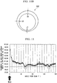
- FIG. 10A is a cross-sectional view showing an example of a thickness distribution of an electric resistance welded steel pipe 301 used as a material for pipe expansion forming
- FIG. 10B is a cross-sectional view showing an example of a thickness distribution of a seamless steel pipe 302 used as a material for the pipe expansion forming
- FIG. 11 is a graph showing the thickness distribution of the electric resistance welded steel pipe 301 in the circumferential direction.
- a horizontal axis indicates an angle from a seam, that is, an angle from a weld 305 formed on the electric resistance welded steel pipe 301.
- a thickness t1 of a portion where the angle from the weld 305 is approximately 60° and a thickness t2 of a portion where the angle is approximately 150° are smaller than the thicknesses t3 to t5 of the other portions, and a thickness deviation occurs.
- the thicknesses t1 and t2 are approximately 98% to 99% of the average value of the thicknesses.
- a thickness deviation occurs in which the thickness t7 ⁇ the thickness t8 ⁇ the thickness t9 is satisfied.
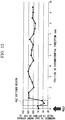
- FIG. 12 is a graph showing the hardness distribution (strength distribution) of the electric resistance welded steel pipe 301 in the circumferential direction. Moreover, in FIG. 12 , a horizontal axis indicates the position in the circumferential direction with the position of the weld of the electric resistance welded steel pipe 301 as a reference. As shown in FIG. 12 , in the electric resistance welded steel pipe 301, a HAZ softened region exists near the weld. This HAZ softened region has a relatively lower hardness than those of other regions and has a hardness of approximately 90% of the average hardness.
- the electric resistance welded steel pipe 301 has a non-uniform thickness distribution and hardness distribution in the circumferential direction
- the seamless steel pipe 302 has a non-uniform thickness distribution in the circumferential direction.
- a force which expands the electric resistance welded steel pipe 301 (or the seamless steel pipe 302) uniformly acts in the circumferential direction.
- a deformation resistance is small in a section having a thin thickness (thin section) and a section having a low hardness (low hardness section)
- the deformation concentrates in these sections.
- a pipe expansion rate is much lower than deforming capacity of the steel pipe, forming defects such as breakage easily occur since thickness reduction rates of these sections are larger than the thickness reduction rates of the other sections.
- the present invention is made in consideration of the above-described circumstances, and an object thereof is to provide a method of manufacturing a flaring-processed metal pipe in which it is possible to prevent occurrence of forming defects such as breakage when the flaring-processed metal pipe is manufactured from a hollow shell including a portion having a relatively small deformation resistance.
- the present invention adopts the following.
- a hollow shell 1 having a hollow circular cross section shown in FIGS. 1A and 1B is expanded and formed to manufacture a flaring-processed metal pipe 20 shown in FIG. 3 .
- the flaring-processed metal pipe 20 is composed of a straight pipe section 21, a pipe expanded section 23 which is formed by expanding the end portion of the hollow shell 1, and a transition section 22 which is provided between the straight pipe section 21 and the pipe expanded section 23.
- the flaring-processed metal pipe 20 is suitably used for automotive parts and the like.
- the material of the hollow shell 1 used for manufacturing the flaring-processed metal pipe 20 is a metal such as iron, aluminum, stainless steel, copper, titanium, magnesium, or steel.
- a value n indicating a work hardening coefficient (distortion-effect index) of the hollow shell 1 is 0.01 to 0.3 from the viewpoint of preventing occurrence of buckling, and a pressing force required for pipe expansion forming from being excessive.
- an r value indicating the deep drawability of the hollow shell 1 is 0.5 to 3 from the viewpoint of preventing occurrence of wrinkle, and the pressing force required for the pipe expansion forming from being excessive.
- the hollow shell 1 is an electric resistance welded pipe, a seamless pipe, a pipe manufactured by extrusion, a pipe manufactured by drawing, or the like.
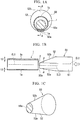
- FIGS. 1A and 1B are views showing the hollow shell 1 and a pipe expansion punch 50 used for expanding the hollow shell 1.
- FIG. 1A is a front view of the hollow shell 1 and the pipe expansion punch 50
- FIG. 1B is a sectional view taken along line A-A in FIG. 1A .
- the hollow shell 1 has a thickness t1 and a thickness t2 which is larger than the thickness t1 when viewed along the circumferential direction thereof. That is, the hollow shell 1 has a thin section 1 a (low deformation resistance section) having the thickness t1 and a thick section 1b (high deformation resistance section) having a thickness t2.
- the thickness t1 of the thin section 1a is less than 99% of an average thickness of the hollow shell 1. Moreover, since the thin section 1a is thinner than the thick section 1b, the thin section 1a is more likely to be deformed than the thick section 1b when pipe expansion forming is performed. In other words, the thin section 1a has less deformation resistance against a force of expanding in the radial direction than the thick section 1b.
- the average thickness of the hollow shell 1 is 0.5 to 30 mm, and for example, the outer diameter of the hollow shell 1 is 15 to 700 mm.
- the ratio of the average thickness of the hollow shell 1 to the outer diameter of the hollow shell 1 is 0.005 to 0.3. In this case, it is possible to efficiently manufacture the flaring-processed metal pipe 20 from the hollow shell 1.
- the thickness of the hollow shell 1 can be obtained using a measuring instrument such as a caliper.
- a measuring instrument such as a caliper.
- the pipe expansion punch 50 includes a cylindrical section 51 having a diameter which is larger than the outer diameter of the hollow shell 1, and a tapered section 52 which is tapered from the cylindrical section 51 toward a tip end surface 50a.
- the tapered section 52 is decentered with a predetermined eccentric amount with respect to the cylindrical section 51. That is, a central axis CL2 of the cylindrical section 51, and a central axis CL3 of the tapered section 52 are parallel to and separated from each other.
- the tapered section 52 has a first tapered surface 52a (first abutment surface) which abuts the thin section 1a of the hollow shell 1, and a second tapered surface 52b (second abutment surface) which abuts the thick section 1b of the hollow shell 1.
- the first tapered surface 52a has a taper angle ⁇ (inclination angle).
- the second tapered surface 52b has a taper angle larger than the taper angle ⁇ , and the maximum taper angle is ⁇ . That is, the taper angle ⁇ is smaller than the taper angle ⁇ .
- the taper angle indicates the inclination angle of the tapered surface with respect to the central axes CL2 and CL3 in a case where the pipe expansion punch 50 is viewed in a cross section including the central axes CL2 and CL3.
- the pipe expansion punch 50 moves along the central axis CL1 of the hollow shell 1 and is inserted into the hollow shell 1 through the opening end 2 of the hollow shell 1. At this time, the pipe expansion punch 50 is inserted into the hollow shell 1 such that the first tapered surface 52a abuts the thin section 1a of the hollow shell 1 and the second tapered surface 52b abuts the thick section 1b of the hollow shell 1.
- the pipe expansion punch 50 is pushed into a predetermined position in the hollow shell 1.
- the pipe expansion punch 50 moves inside the hollow shell 1 while the tapered section 52 of the pipe expansion punch 50 abutting the hollow shell 1, the hollow shell 1 is spread in the radial direction thereof and is expanded along the shape of the pipe expansion punch 50.
- an intermediate formed product 10 shown in FIG. 2 can be obtained from the hollow shell 1.
- the pipe expansion punch 50 can be pushed into the hollow shell 1 using a pressurization mechanism such as a hydraulic cylinder, a gas cylinder, a spring, or a rubber.
- a pressurization mechanism such as a hydraulic cylinder, a gas cylinder, a spring, or a rubber.
- the hollow shell 1 is expanded in the radial direction while the first tapered surface 52a of the pipe expansion punch 50 abuts the thin section 1 a of the hollow shell 1 and the second tapered surface 52b of the pipe expansion punch 50 abuts the thick section 1 b of the hollow shell 1.
- the thick section 1b is preferentially subjected to tensile processing with respect to the thin section 1a.
- a thickness reduction rate of the thin section 1a of the hollow shell 1 can be smaller than the thickness reduction rate of the thick section 1b of the hollow shell 1. That is, when the hollow shell 1 is expanded, since it is possible to prevent concentration of deformation in the thin section 1a, it is possible to prevent occurrence of forming defects such as breakage in the thin section 1a.
- the intermediate formed product 10 includes a straight pipe section 11 which is a non-processed portion, a pipe expanded section 13, and a transition section 12 which is provided between the straight pipe section 11 and the pipe expanded section 13.
- the pipe expanded section 13 of the intermediate formed product 10 has a portion 13a corresponding to the thin section 1a of the hollow shell 1 and a portion 13b corresponding to the thick section 1b of the hollow shell 1.
- the straight pipe section 11 of the intermediate formed product 10 has a portion 11a corresponding to the thin section 1a of the hollow shell 1 and a portion 11b corresponding to the thick section 1b of the hollow shell 1.
- the hollow shell 1 is expanded and formed such that the thickness reduction rate of the thin section 1a of the hollow shell 1 is smaller than the thickness reduction rate of the thick section 1b of the hollow shell 1. Therefore, in the intermediate formed product 10, a value (the thickness reduction rate of the thin section 1 a) obtained by dividing a difference value (the thickness reduction amount of the thin section 1a of the hollow shell 1) between the thickness t1 of the portion 11 a and a thickness t1' of the portion 13a by the thickness t1 is smaller than a value (the thickness reduction rate of the thick section 1b) obtained by dividing a difference value (the thickness reduction amount of the thick section 1b of the hollow shell 1) between the thickness t2 of the portion 11 b and a thickness t2' of the portion 13b by the thickness t2.
- the diameter expansion amount L1 of the thin section 1a of the hollow shell 1 is less than 0.5 times a diameter expansion amount L2 of the thick section 1b of the hollow shell 1.
- the “diameter expansion amount” means the length of the hollow shell 1 expanded in the radial direction, and specifically, means the dimension (distance) between the inner surface of the pipe expanded section after processing and the inner surface of the hollow shell 1. That is, as shown in FIG. 2 , "the diameter expansion amount L1 of the thin section 1a of the hollow shell 1" indicates the dimension between the inner surface of the portion 11a of the intermediate formed product 10 and the inner surface of the portion 13a of the intermediate formed product 10. Moreover, the “diameter expanded amount L2 of the thick section 1b of the hollow shell 1" indicates the dimension between the inner surface of the portion 11b of the intermediate formed product 10 and the inner surface of the portion 13b of the intermediate formed product 10.
- the intermediate formed product 10 may be formed into the flaring-processed metal pipe 20 using a forming punch 60 and a stationary die 70 shown in FIG. 3 .
- the forming punch 60 has a cylindrical section 61, and a tapered section 62 which is tapered from the cylindrical section 61 toward the tip end surface 60a.
- a central axis CL4 of the cylindrical section 61 coincides with the central axis of the tapered section 62. That is, the cylindrical section 61 and the tapered section 62 are coaxially formed.
- the cylindrical section 61 has an outer surface shape which coincides with the shape of the inner surface of the pipe expanded section 23 of the flaring-processed metal pipe 20.
- the tapered section 62 has an outer surface shape which coincides with the inner surface of the transition section 23 of the flaring-processed metal pipe 20, and has a taper angle ⁇ .
- the stationary die 70 includes a bottom wall section 71 which abuts the end surface of the straight pipe section 11 of the intermediate formed product 10, and a side wall section 72 which abuts the outer surface of the straight pipe section 11 of the intermediate formed product 10. Moreover, the inner surface shape of the side wall section 72 coincides with the outer surface shape of the flaring-processed metal pipe 20.
- the intermediate formed product 10 is formed into the flaring-processed metal pipe 20
- the intermediate formed product 10 is set in the stationary die 70 along the bottom wall section 71 and the side wall section 72 of the stationary die 70.
- the forming punch 60 is pushed into the intermediate formed product 10.
- the forming punch 60 has the shape conforming to the shape of the inner surface of the flaring-processed metal pipe 20 and the side wall section 72 of the stationary die 70 has the shape conforming to the outer surface shape of the flaring-processed metal pipe 20, it is possible to obtain the flaring-processed metal pipe 20 by pushing the forming punch 60 into the intermediate formed product 10.
- the force for expanding the thin section 1a of the hollow shell 1 in the radial direction is weakened while the force for expanding the thick section 1b of the hollow shell 1 in the radial direction becomes stronger. That is, since the hollow shell 1 is expanded such that the thickness reduction rate of the thin section 1a of the hollow shell 1 is smaller than the thickness reduction rate of the thick section 1b of the hollow shell 1, it is possible to prevent concentration of deformation in the thin section 1a, and it is possible to prevent breakage or the like of the hollow material 1. As a result, it is possible to manufacture a flaring-processed metal pipe having a larger pipe expansion rate than that of the related art.
- the hollow shell 1 is expanded such that the thickness reduction rate of the thin section 1a of the hollow shell 1 is smaller than the thickness reduction rate of the thick section 1b of the hollow shell 1, it is possible to manufacture a flaring-processed metal pipe including a pipe expanded section having a uniform thickness from the hollow shell 1 having a non-uniform thickness distribution.
- the hollow shell 1 is formed into the intermediate formed product 10 if the pipe expansion rate of the intermediate formed product 10 is decreased, effects for preventing the breakage of the thin section 1a of the hollow shell 1 decrease. Therefore, preferably, the hollow shell 1 is formed into the intermediate formed product 10 so that the pipe expansion rate of the intermediate formed product 10 becomes 50% or more with respect to the pipe expansion rate of the flaring-processed metal pipe 20.
- the material of the hollow shell 1 is an aluminum alloy
- the material of the hollow shell 1 is stainless steel
- forming defects easily occur when the pipe expansion forming is performed.
- the effects for preventing breakage in the thin section 1a increase.
- the flaring-processed metal pipe may be manufactured from a hollow shell having a non-uniform hardness distribution in the circumferential direction.
- the hardness distribution is ascertained by a tensile test, hardness measurement or the like
- the first tapered surface 52a of the pipe expansion punch 50 may abut a low hardness section (low deformation resistance section) having a relatively low hardness
- the second tapered surface 52b of the pipe expansion punch 50 may abut a high hardness section (high deformation resistance section) having a relatively high hardness.
- a portion having a hardness which is less than 95% with respect to the average value of the hardness of the hollow shell can be specified as the low hardness section.
- the hollow shell has both a non-uniform thickness distribution and a non-uniform hardness distribution
- a portion in which the product value between the thickness and the hardness is less than 95% of the average value is specified as the low deformation resistance section, and the first tapered surface 52a of the pipe expansion punch 50 may abut the low deformation resistance section.
- the case where the first tapered surface 52a of the pipe expansion punch 50 has the taper angle ⁇ (refer to FIG. 1B or the like) is described.
- a pipe expansion punch 80 having the taper angle ⁇ of 0° may be press-fitted into the hollow shell 1 to form the hollow shell 1 into the intermediate formed product 90.
- the hollow shell 1 may be expanded and formed using the pipe expansion punch 80 having a cutout part 85 at the tip and a stationary die 100 having a bottom wall section 101 and a side wall section 102.
- the pipe expansion punch 80 since the cutout part 85 is provided, the pipe expansion punch 80 can be smoothly pushed into the hollow shell 1.
- a gap between the first tapered surface 52a and the side wall section 102 of the stationary die 100 is set to be 0.9 to 0.99 times the thickness of the hollow shell 1. In this case, occurrence of deformation at the thin section 1a can be more reliably prevented.
- the hollow shell 1 having the thin section 1a provided at one location is expanded and formed is shown.
- a hollow shell 5 having the thin sections 1a provided at two locations may be expanded and formed.
- a hollow shell 7 having the thin sections 1a provided at three locations may be expanded and formed.
- a flaring-processed metal pipe 220 shown in FIG. 8C is manufactured from the hollow shell 1 using a pipe expansion punch 250 shown in FIG. 8A .
- the pipe expansion punch 250 has a cylindrical section 251 and a tapered section 252.
- the pipe expansion punch 250 is different from the pipe expansion punch 50 of the first embodiment in that the cylindrical section 251 and the tapered section 252 are formed along the same central axis CL5.
- FIG. 8B is a view showing a state in which the pipe expansion punch 250 is press-fitted to a predetermined position in the hollow shell 1.
- the thick section 1b of the hollow shell 1 abuts the cylindrical section 251 of the pipe expansion punch 250
- the thin section 1a of the hollow shell 1 abuts the tapered section 252 of the pipe expansion punch 250.
- FIG. 8C is a view showing a state in which the pipe expansion punch 250 is further press-fitted into the hollow shell 1 from the state shown in FIG. 8B .
- the flaring-processed metal pipe 220 can be obtained by press-fitting the pipe expansion punch 250 into the hollow shell 1 until the thin section 1a abuts the cylindrical section 251 of the pipe expansion punch 250.
- the thick section 1b is preferentially subjected to tensile processing. That is, similarly to the case of the first embodiment, it is possible to prevent occurrence of forming defects in the thin section 1 a by allowing the thickness reduction rate of the thin section 1 a to be smaller than the thickness reduction rate of the thick section 1b.
- a flaring-processed metal pipe was manufactured according to a related art in which a flaring-processed metal pipe was manufactured using only a forming punch.
- the forming defects were evaluated by visually checking the presence or absence of breakage.
- the hollow shell 1 As the hollow shell 1, a seamless steel pipe having 73 mm in the outer diameter and 6 mm in the average thickness was used. The thickness of the thin section 1a of the hollow shell 1 was 5.6 mm, and the thickness of the thick section 1b of the hollow shell 1 was 6.4 mm.
- the pipe expansion punch 50 and the forming punch 60 were used.
- the taper angle ⁇ was 4.5°, the taper angle ⁇ was 24.6°, and the diameter of the cylindrical section 51 was 81.2 mm.
- the taper angle ⁇ was 15°, and the diameter of the cylindrical section 61 was 81.2 mm.
- the inner diameter D (refer to FIG. 3 ) of the side wall sections 72 was 93.2 mm.
- the intermediate formed product 10 was manufactured by pushing the pipe expansion punch 50 into the hollow shell 1 to expand the hollow shell 1. At this time, the intermediate formed product 10 was manufactured such that L1 shown in FIG. 2 was 0.17 times L2.
- the intermediate formed product 10 was disposed on the stationary die 70 and the forming punch 60 was pushed into the intermediate formed product 10 to manufacture the flaring-processed metal pipe 20.
- Forming defects such as cracks did not occur in the intermediate formed product 10 and the flaring-processed metal pipe 20.
- the pipe expansion rate of the flaring-processed metal pipe 20 was 30%.
- an electric resistance welded steel pipe having 90.0 mm in the outer diameter and 2.8 mm in the average thickness was used as the hollow shell 1.
- the tensile strength TS was 80 kgf/mm 2 (785MPa), and the hardness distribution in the circumferential direction was the distribution shown in FIG. 9 .
- the pipe expansion punch 50 and the forming punch 60 were used.
- the taper angle ⁇ was 4.5°, the taper angle ⁇ was 24.6°, and the diameter of the cylindrical section 51 was 112.4 mm.
- the taper angle ⁇ was 15°, and the diameter of the cylindrical section 61 was 112.4 mm.
- the inner diameter D (refer to FIG. 3 ) of the side wall sections 72 was 117 mm.
- the intermediate formed product 10 was manufactured by pushing the pipe expansion punch 50 into the hollow shell 1 to expand the hollow shell 1. At this time, the intermediate formed product 10 was manufactured such that L1 shown in FIG. 2 was 0.17 times L2.
- the intermediate formed product 10 was disposed on the stationary die 70 and the forming punch 60 was pushed into the intermediate formed product 10 to manufacture the flaring-processed metal pipe 20.
- Forming defects such as cracks did not occur in the intermediate formed product 10 and the flaring-processed metal pipe 20.
- the pipe expansion rate of the flaring-processed metal pipe 20 was 30%.
- Example 2 As a hollow shell 1, the same electric resistance welded steel pipe as that of Example 2 was used.
- the pipe expansion punch 50 and the forming punch 60 were used.
- the taper angle ⁇ was 7.5°
- the taper angle ⁇ was 21.9°
- the diameter of the cylindrical section 51 was 129.4 mm.
- the taper angle ⁇ was 15°, and the diameter of the cylindrical section 61 was 129.4 mm.
- the inner diameter D (refer to FIG. 3 ) of the side wall sections 72 was 135 mm
- the intermediate formed product 10 was manufactured.
- the intermediate formed product 10 was manufactured such that L1 shown in FIG. 2 was 0.33 times L2.
- Forming defects such as cracks did not occur in the intermediate formed product 10 and the flaring-processed metal pipe 20.
- the pipe expansion rate of the flaring-processed metal pipe 20 was 50%.
- Example 2 The same electric resistance welded steel pipe as that of Example 2 was used.
- the hollow shell 1 was disposed in the stationary die 70, the forming punch 60 was pushed into the hollow shell 1 to expand the hollow shell, and the flaring-processed metal pipe was manufactured.
- the pipe expansion rate of the flaring-processed metal pipe was 30%, and the forming defects such as cracks did not occur in the flaring-processed metal pipe.
- the pipe expansion rate was as low as 30%, it was considered that forming defects did not occur even when the pipe expansion punch 50 was not used.
- Example 2 The same electric resistance welded steel pipe as that of Example 2 was used.
- the pipe expansion punch 50 was not used, and only the forming punch 60 was used (that is, the same as Reference Example 1).
- the hollow shell 1 was disposed in the stationary die 70, the forming punch 60 was pushed into the hollow shell 1 to expand the hollow shell, and the flaring-processed metal pipe was manufactured.
- the pipe expansion rate of the flaring-processed metal pipe was 50%, and cracks occurred in the flaring-processed metal pipe.
- Example 3 Accordingly, according to the comparison between Example 3 and Comparative Example 1, with respect to a product having a high pipe expansion rate in which cracks were generated in the related art, it was configured that the product could be manufactured without occurrence of cracks.
- the hollow shell 1 is formed into the intermediate formed product 10 using a pipe expansion punch 50 is described.
- the hollow shell 1 may be formed stepwise (at a plurality of times) using a plurality of pipe expansion punches having different outer diameters.
- the intermediate formed product 10 is formed into the flaring-processed metal pipe 20 using the forming punch 60 is described.
- the intermediate formed product 10 obtained by the pipe expansion punch 50 without using the forming punch 60 may be the flaring-processed metal pipe. In this case, it is possible to obtain an eccentric flaring-processed metal pipe.
- a method of manufacturing a flaring-processed metal pipe in which it is possible to prevent occurrence of forming defects such as breakage when a flaring-processed metal pipe is manufactured from a hollow shell including a portion having a relatively small deformation resistance.
Landscapes
- Engineering & Computer Science (AREA)
- Mechanical Engineering (AREA)
- Shaping Metal By Deep-Drawing, Or The Like (AREA)
- Forging (AREA)
Abstract
Description
- The present invention relates to a method of manufacturing a flaring-processed metal pipe.
- Priority is claimed on Japanese Patent Application No.
2014-264337, filed on December 26,2014 - As a method of manufacturing a flaring-processed metal pipe, a method of press-fitting a tapered pipe expansion punch (punch) from an open end of a metal pipe (raw pipe) which is a material and expanding the metal pipe in the radial direction thereof to form a pipe expanded section in the metal pipe is known (for example, refer to
Patent Documents 1 and 2). - However, in the above-described manufacturing method, due to various factors, forming defects such as cracks in the pipe expanded section or buckling at the root of the pipe expanded section occur. Accordingly, it is required to prevent the occurrence of the above-described forming defects when the flaring-processed metal pipe is manufactured (the metal pipe is expanded and formed) from a raw pipe.
-
- [Patent Document 1] Japanese Patent No.
4798875 - [Patent Document 2] Japanese Patent No.
5221910 - The inventors focused on a thickness distribution and a hardness distribution in the circumferential direction of the raw pipe as a cause of forming defects in the pipe expansion forming (pipe expansion processing) of the metal pipe.
-
FIG. 10A is a cross-sectional view showing an example of a thickness distribution of an electric resistance weldedsteel pipe 301 used as a material for pipe expansion forming, andFIG. 10B is a cross-sectional view showing an example of a thickness distribution of aseamless steel pipe 302 used as a material for the pipe expansion forming. In addition,FIG. 11 is a graph showing the thickness distribution of the electric resistance weldedsteel pipe 301 in the circumferential direction. InFIG. 11 , a horizontal axis indicates an angle from a seam, that is, an angle from aweld 305 formed on the electric resistance weldedsteel pipe 301. - As shown in
FIGS. 10A and11 , in the electric resistance weldedsteel pipe 301, a thickness t1 of a portion where the angle from theweld 305 is approximately 60° and a thickness t2 of a portion where the angle is approximately 150° are smaller than the thicknesses t3 to t5 of the other portions, and a thickness deviation occurs. Moreover, the thicknesses t1 and t2 are approximately 98% to 99% of the average value of the thicknesses. - In addition, as shown in
FIG. 10B , in theseamless steel pipe 302, a thickness deviation occurs in which the thickness t7 < the thickness t8 < the thickness t9 is satisfied. -
FIG. 12 is a graph showing the hardness distribution (strength distribution) of the electric resistance weldedsteel pipe 301 in the circumferential direction. Moreover, inFIG. 12 , a horizontal axis indicates the position in the circumferential direction with the position of the weld of the electric resistance weldedsteel pipe 301 as a reference. As shown inFIG. 12 , in the electric resistance weldedsteel pipe 301, a HAZ softened region exists near the weld. This HAZ softened region has a relatively lower hardness than those of other regions and has a hardness of approximately 90% of the average hardness. - As described above, the electric resistance welded
steel pipe 301 has a non-uniform thickness distribution and hardness distribution in the circumferential direction, and theseamless steel pipe 302 has a non-uniform thickness distribution in the circumferential direction. When the electric resistance welded steel pipe 301 (or the seamless steel pipe 302) having the non-uniform distribution is uniformly flared and formed (expanded and formed) in the circumferential direction, a force which expands the electric resistance welded steel pipe 301 (or the seamless steel pipe 302) uniformly acts in the circumferential direction. In addition, since a deformation resistance is small in a section having a thin thickness (thin section) and a section having a low hardness (low hardness section), the deformation concentrates in these sections. As a result, despite the fact that a pipe expansion rate is much lower than deforming capacity of the steel pipe, forming defects such as breakage easily occur since thickness reduction rates of these sections are larger than the thickness reduction rates of the other sections. - The present invention is made in consideration of the above-described circumstances, and an object thereof is to provide a method of manufacturing a flaring-processed metal pipe in which it is possible to prevent occurrence of forming defects such as breakage when the flaring-processed metal pipe is manufactured from a hollow shell including a portion having a relatively small deformation resistance.
- In order to solve the above problem, the present invention adopts the following.
- (1) According to an aspect of the present invention, there is provided a method of manufacturing a flaring-processed metal pipe having a pipe expanded section from a hollow shell including a plurality of portions having different deformation resistances when viewed in a circumferential direction, the method including: among the plurality of portions, specifying a portion having a relatively small deformation resistance as a low deformation resistance section, and a portion having a relatively larger deformation resistance than that of the low deformation resistance section as a high deformation resistance section; and press-fitting a pipe expansion punch into the hollow shell and expanding the hollow shell, in the press-fitting and the expanding, a thickness reduction rate of the low deformation resistance section is smaller than a thickness reduction rate of the high deformation resistance section.
- (2) In the aspect described in the above (1), it may be configured as follows: the pipe expansion punch includes a first abutment surface which abuts the low deformation resistance section of the hollow shell, and a second abutment surface which abuts the high deformation resistance section of the hollow shell, and an inclination angle of the first abutment surface with respect to the central axis of the pipe expansion punch is smaller than an inclination angle of the second abutment surface with respect to the central axis, and in the press-fitting and the expanding, the pipe expansion punch is press-fitted into the hollow shell while the first abutment surface of the pipe expansion punch abuts the low deformation resistance section of the hollow shell and the second abutment surface of the pipe expansion punch abuts the high deformation resistance section of the hollow shell.
- (3) In the aspect described in the above (2), the inclination angle of the first abutment surface of the pipe expansion punch may be 0°.
- (4) In the aspect described in the above (2) or (3), it may be configured as follows: the press-fitting and the expanding include press-fitting the pipe expansion punch into the hollow shell to obtain an intermediate formed product from the hollow shell, and press-fitting a forming punch having a shape which coincides with an inner surface of the pipe expanded section of the flaring-processed metal pipe into the intermediate formed product.
- (5) In the aspect described in the above (4), in the press-fitting of the pipe expansion punch, the pipe expansion punch may be press-fitted into the hollow shell such that a diameter expansion amount of the low deformation resistance section of the hollow shell is less than 0.5 times a diameter expansion amount of the high deformation resistance section of the hollow shell.
- (6) In the aspect of any one of the above (1) to (5), the hollow shell may be an electric resistance welded steel pipe or a seamless steel pipe.
- According to each of the aspects of the present invention, it is possible to prevent occurrence of forming defects such as breakage when a flaring-processed metal pipe is manufactured from a hollow shell including a portion having a relatively small deformation resistance.
-
-
FIG. 1A is a front view showing a hollow shell and a pipe expansion punch used in a method of manufacturing a flaring-processed metal pipe according to a first embodiment of the present invention. -
FIG. 1B is a sectional view taken along line A-A of the hollow shell and the pipe expansion punch shown inFIG. 1A . -
FIG. 1C is a schematic perspective view showing the pipe expansion punch. -
FIG. 2 is a sectional view showing a state in which the pipe expansion punch is press-fitted into the hollow shell. -
FIG. 3 is a sectional view showing a state in which a forming punch is press-fitted to an intermediate formed product obtained by expanding the hollow shell using the pipe expansion punch. -
FIG. 4A is a sectional view showing a first modification example of the method of manufacturing the flaring-processed metal pipe. -
FIG. 4B is a sectional view showing the continuation of the manufacturing method according to the modification example. -
FIG. 5A is a sectional view showing a second modification of the method of manufacturing the flaring-processed metal pipe. -
FIG. 5B is a sectional view showing the continuation of the manufacturing method according to the modification example. -
FIG. 6A is a view showing a third modification example of the method of manufacturing the flaring-processed metal pipe, and is a front view showing a pipe expansion punch and a hollow shell used in the modification example. -
FIG. 6B is a schematic perspective view showing the pipe expansion punch. -
FIG. 7A is a view showing a fourth modification example of the method for manufacturing the flaring-processed metal pipe, and is a front view showing a pipe expansion punch and a hollow shell used in the modification example. -
FIG. 7B is a schematic perspective view showing the pipe expansion punch. -
FIG. 8A is a sectional view showing a hollow shell and a pipe expansion punch used in a method of manufacturing a flaring-processed metal pipe according to a second embodiment of the present invention. -
FIG. 8B is a view for explaining the method of manufacturing the flaring-processed metal pipe, and is a sectional view showing a state in which the pipe expansion punch is press-fitted into the hollow shell. -
FIG. 8C is a sectional view showing the continuation of the method of manufacturing the flaring-processed metal pipe. -
FIG. 9 is a diagram showing a hardness distribution of a hollow shell used in Example 2. -
FIG. 10A is a cross-sectional view showing an electric resistance welded steel pipe and is a view showing an example of a thickness distribution of the electric resistance welded steel pipe. -
FIG. 10B is a cross-sectional view showing a seamless steel pipe, and a view showing an example of a thickness distribution of the seamless steel pipe. -
FIG. 11 is a graph showing a thickness distribution of the electric resistance welded steel pipe in a circumferential direction. -
FIG. 12 is a graph showing the hardness distribution of the electric resistance welded steel pipe in the circumferential direction. - Hereinafter, embodiments of the present invention will be described in detail with reference to the drawings. In the present specification and the drawings, the same reference numerals are assigned to constituent elements having substantially the same functional configuration, and overlapping description thereof will be omitted.
- In a method of manufacturing a flaring-processed metal pipe according to the first embodiment of the present invention, a
hollow shell 1 having a hollow circular cross section shown inFIGS. 1A and 1B is expanded and formed to manufacture a flaring-processedmetal pipe 20 shown inFIG. 3 . The flaring-processedmetal pipe 20 is composed of astraight pipe section 21, a pipe expandedsection 23 which is formed by expanding the end portion of thehollow shell 1, and atransition section 22 which is provided between thestraight pipe section 21 and the pipe expandedsection 23. In addition, for example, the flaring-processedmetal pipe 20 is suitably used for automotive parts and the like. - For example, the material of the
hollow shell 1 used for manufacturing the flaring-processedmetal pipe 20 is a metal such as iron, aluminum, stainless steel, copper, titanium, magnesium, or steel. Preferably, a value n indicating a work hardening coefficient (distortion-effect index) of thehollow shell 1 is 0.01 to 0.3 from the viewpoint of preventing occurrence of buckling, and a pressing force required for pipe expansion forming from being excessive. Preferably, an r value indicating the deep drawability of thehollow shell 1 is 0.5 to 3 from the viewpoint of preventing occurrence of wrinkle, and the pressing force required for the pipe expansion forming from being excessive. - For example, the
hollow shell 1 is an electric resistance welded pipe, a seamless pipe, a pipe manufactured by extrusion, a pipe manufactured by drawing, or the like. -
FIGS. 1A and 1B are views showing thehollow shell 1 and apipe expansion punch 50 used for expanding thehollow shell 1. In addition,FIG. 1A is a front view of thehollow shell 1 and thepipe expansion punch 50, andFIG. 1B is a sectional view taken along line A-A inFIG. 1A . - As shown in
FIGS. 1A and 1B , thehollow shell 1 has a thickness t1 and a thickness t2 which is larger than the thickness t1 when viewed along the circumferential direction thereof. That is, thehollow shell 1 has athin section 1 a (low deformation resistance section) having the thickness t1 and athick section 1b (high deformation resistance section) having a thickness t2. - For example, the thickness t1 of the
thin section 1a is less than 99% of an average thickness of thehollow shell 1. Moreover, since thethin section 1a is thinner than thethick section 1b, thethin section 1a is more likely to be deformed than thethick section 1b when pipe expansion forming is performed. In other words, thethin section 1a has less deformation resistance against a force of expanding in the radial direction than thethick section 1b. - For example, the average thickness of the
hollow shell 1 is 0.5 to 30 mm, and for example, the outer diameter of thehollow shell 1 is 15 to 700 mm. Preferably, the ratio of the average thickness of thehollow shell 1 to the outer diameter of thehollow shell 1 is 0.005 to 0.3. In this case, it is possible to efficiently manufacture the flaring-processedmetal pipe 20 from thehollow shell 1. - For example, the thickness of the
hollow shell 1 can be obtained using a measuring instrument such as a caliper. In addition, it is possible to specify thethin section 1a and thethick section 1b by ascertaining the thickness distribution of thehollow shell 1. - As shown in
FIGS. 1A to 1C , thepipe expansion punch 50 includes acylindrical section 51 having a diameter which is larger than the outer diameter of thehollow shell 1, and a taperedsection 52 which is tapered from thecylindrical section 51 toward atip end surface 50a. The taperedsection 52 is decentered with a predetermined eccentric amount with respect to thecylindrical section 51. That is, a central axis CL2 of thecylindrical section 51, and a central axis CL3 of the taperedsection 52 are parallel to and separated from each other. - In addition, the tapered
section 52 has a firsttapered surface 52a (first abutment surface) which abuts thethin section 1a of thehollow shell 1, and a secondtapered surface 52b (second abutment surface) which abuts thethick section 1b of thehollow shell 1. - The first
tapered surface 52a has a taper angle α (inclination angle). The secondtapered surface 52b has a taper angle larger than the taper angle α, and the maximum taper angle is β. That is, the taper angle α is smaller than the taper angle β. Moreover, the taper angle indicates the inclination angle of the tapered surface with respect to the central axes CL2 and CL3 in a case where thepipe expansion punch 50 is viewed in a cross section including the central axes CL2 and CL3. - First, as shown in
FIGS. 1A and 1B , when the flaring-processedmetal pipe 20 is manufactured from thehollow shell 1, thepipe expansion punch 50 moves along the central axis CL1 of thehollow shell 1 and is inserted into thehollow shell 1 through the openingend 2 of thehollow shell 1. At this time, thepipe expansion punch 50 is inserted into thehollow shell 1 such that the firsttapered surface 52a abuts thethin section 1a of thehollow shell 1 and the secondtapered surface 52b abuts thethick section 1b of thehollow shell 1. - In addition, as shown in
FIG. 2 , thepipe expansion punch 50 is pushed into a predetermined position in thehollow shell 1. At this time, since thepipe expansion punch 50 moves inside thehollow shell 1 while the taperedsection 52 of thepipe expansion punch 50 abutting thehollow shell 1, thehollow shell 1 is spread in the radial direction thereof and is expanded along the shape of thepipe expansion punch 50. As a result, an intermediate formedproduct 10 shown inFIG. 2 can be obtained from thehollow shell 1. - For example, the
pipe expansion punch 50 can be pushed into thehollow shell 1 using a pressurization mechanism such as a hydraulic cylinder, a gas cylinder, a spring, or a rubber. - In the above-described process, the
hollow shell 1 is expanded in the radial direction while the firsttapered surface 52a of thepipe expansion punch 50 abuts thethin section 1 a of thehollow shell 1 and the secondtapered surface 52b of thepipe expansion punch 50 abuts thethick section 1 b of thehollow shell 1. At this time, since the taper angle of the secondtapered surface 52b is larger than the taper angle of the firsttapered surface 52a, thethick section 1b is preferentially subjected to tensile processing with respect to thethin section 1a. As a result, a thickness reduction rate of thethin section 1a of thehollow shell 1 can be smaller than the thickness reduction rate of thethick section 1b of thehollow shell 1. That is, when thehollow shell 1 is expanded, since it is possible to prevent concentration of deformation in thethin section 1a, it is possible to prevent occurrence of forming defects such as breakage in thethin section 1a. - As shown in
FIG. 2 , the intermediate formedproduct 10 includes astraight pipe section 11 which is a non-processed portion, a pipe expandedsection 13, and atransition section 12 which is provided between thestraight pipe section 11 and the pipe expandedsection 13. - The pipe expanded
section 13 of the intermediate formedproduct 10 has aportion 13a corresponding to thethin section 1a of thehollow shell 1 and aportion 13b corresponding to thethick section 1b of thehollow shell 1. In addition, thestraight pipe section 11 of the intermediate formedproduct 10 has aportion 11a corresponding to thethin section 1a of thehollow shell 1 and aportion 11b corresponding to thethick section 1b of thehollow shell 1. - As described above, in the above-described process, the
hollow shell 1 is expanded and formed such that the thickness reduction rate of thethin section 1a of thehollow shell 1 is smaller than the thickness reduction rate of thethick section 1b of thehollow shell 1. Therefore, in the intermediate formedproduct 10, a value (the thickness reduction rate of thethin section 1 a) obtained by dividing a difference value (the thickness reduction amount of thethin section 1a of the hollow shell 1) between the thickness t1 of theportion 11 a and a thickness t1' of theportion 13a by the thickness t1 is smaller than a value (the thickness reduction rate of thethick section 1b) obtained by dividing a difference value (the thickness reduction amount of thethick section 1b of the hollow shell 1) between the thickness t2 of theportion 11 b and a thickness t2' of theportion 13b by the thickness t2. - Moreover, from the viewpoint of decreasing the amount of deformation of the
thin section 1a and avoiding breakage of thethin section 1a, the diameter expansion amount L1 of thethin section 1a of thehollow shell 1 is less than 0.5 times a diameter expansion amount L2 of thethick section 1b of thehollow shell 1. - Here, the "diameter expansion amount" means the length of the
hollow shell 1 expanded in the radial direction, and specifically, means the dimension (distance) between the inner surface of the pipe expanded section after processing and the inner surface of thehollow shell 1. That is, as shown inFIG. 2 , "the diameter expansion amount L1 of thethin section 1a of thehollow shell 1" indicates the dimension between the inner surface of theportion 11a of the intermediate formedproduct 10 and the inner surface of theportion 13a of the intermediate formedproduct 10. Moreover, the "diameter expanded amount L2 of thethick section 1b of thehollow shell 1" indicates the dimension between the inner surface of theportion 11b of the intermediate formedproduct 10 and the inner surface of theportion 13b of the intermediate formedproduct 10. - Subsequently, the intermediate formed
product 10 may be formed into the flaring-processedmetal pipe 20 using a formingpunch 60 and astationary die 70 shown inFIG. 3 . As shown inFIG. 3 , the formingpunch 60 has acylindrical section 61, and a taperedsection 62 which is tapered from thecylindrical section 61 toward thetip end surface 60a. Unlike thepipe expansion punch 50, in the formingpunch 60, a central axis CL4 of thecylindrical section 61 coincides with the central axis of the taperedsection 62. That is, thecylindrical section 61 and the taperedsection 62 are coaxially formed. - The
cylindrical section 61 has an outer surface shape which coincides with the shape of the inner surface of the pipe expandedsection 23 of the flaring-processedmetal pipe 20. The taperedsection 62 has an outer surface shape which coincides with the inner surface of thetransition section 23 of the flaring-processedmetal pipe 20, and has a taper angle γ. - As shown in
FIG. 3 , thestationary die 70 includes abottom wall section 71 which abuts the end surface of thestraight pipe section 11 of the intermediate formedproduct 10, and aside wall section 72 which abuts the outer surface of thestraight pipe section 11 of the intermediate formedproduct 10. Moreover, the inner surface shape of theside wall section 72 coincides with the outer surface shape of the flaring-processedmetal pipe 20. - When the intermediate formed
product 10 is formed into the flaring-processedmetal pipe 20, first, the intermediate formedproduct 10 is set in thestationary die 70 along thebottom wall section 71 and theside wall section 72 of thestationary die 70. Thereafter, the formingpunch 60 is pushed into the intermediate formedproduct 10. As described above, since the formingpunch 60 has the shape conforming to the shape of the inner surface of the flaring-processedmetal pipe 20 and theside wall section 72 of thestationary die 70 has the shape conforming to the outer surface shape of the flaring-processedmetal pipe 20, it is possible to obtain the flaring-processedmetal pipe 20 by pushing the formingpunch 60 into the intermediate formedproduct 10. - According to the method of manufacturing the flaring-processed
metal pipe 20 according to the above-described present embodiment, since thehollow shell 1 is expanded using thepipe expansion punch 50, the force for expanding thethin section 1a of thehollow shell 1 in the radial direction is weakened while the force for expanding thethick section 1b of thehollow shell 1 in the radial direction becomes stronger. That is, since thehollow shell 1 is expanded such that the thickness reduction rate of thethin section 1a of thehollow shell 1 is smaller than the thickness reduction rate of thethick section 1b of thehollow shell 1, it is possible to prevent concentration of deformation in thethin section 1a, and it is possible to prevent breakage or the like of thehollow material 1. As a result, it is possible to manufacture a flaring-processed metal pipe having a larger pipe expansion rate than that of the related art. - Moreover, according to the method of manufacturing the flaring-processed
metal pipe 20 according to the present embodiment, since thehollow shell 1 is expanded such that the thickness reduction rate of thethin section 1a of thehollow shell 1 is smaller than the thickness reduction rate of thethick section 1b of thehollow shell 1, it is possible to manufacture a flaring-processed metal pipe including a pipe expanded section having a uniform thickness from thehollow shell 1 having a non-uniform thickness distribution. - Here, the above-described "pipe expansion rate" means a rate at which the outer diameter of the pipe expanded section after the pipe expansion forming is performed is increased with respect to the outer diameter of the
hollow shell 1. That is, in a case where the pipe expansion rate is defined as P (%), the outer diameter of the pipe expanded section after pipe expansion forming performed is defined as d1 (mm), and the outer diameter of thehollow shell 1 is defined as d2 (mm), the pipe expansion rate P is represented by the following Expression (1).
- In addition, when the
hollow shell 1 is formed into the intermediate formedproduct 10, if the pipe expansion rate of the intermediate formedproduct 10 is decreased, effects for preventing the breakage of thethin section 1a of thehollow shell 1 decrease. Therefore, preferably, thehollow shell 1 is formed into the intermediate formedproduct 10 so that the pipe expansion rate of the intermediate formedproduct 10 becomes 50% or more with respect to the pipe expansion rate of the flaring-processedmetal pipe 20. - In addition, compared to a case where the material of the
hollow shell 1 is an aluminum alloy, in a case where the material of thehollow shell 1 is stainless steel, forming defects easily occur when the pipe expansion forming is performed. Accordingly, compared to the case where the material of thehollow shell 1 is the aluminum alloy, in the case where the material of thehollow shell 1 is stainless steel, the effects for preventing breakage in thethin section 1a increase. - In the present embodiment, the case where the
hollow shell 1 has thethin section 1a and thethick section 1b (that is, the case where the thickness distribution in the circumferential direction is non-uniform) is described. However, for example, the flaring-processed metal pipe may be manufactured from a hollow shell having a non-uniform hardness distribution in the circumferential direction. In this case, the hardness distribution is ascertained by a tensile test, hardness measurement or the like, the firsttapered surface 52a of thepipe expansion punch 50 may abut a low hardness section (low deformation resistance section) having a relatively low hardness, and the secondtapered surface 52b of thepipe expansion punch 50 may abut a high hardness section (high deformation resistance section) having a relatively high hardness. In this case, for example, a portion having a hardness which is less than 95% with respect to the average value of the hardness of the hollow shell can be specified as the low hardness section. - In addition, for example, in a case where the hollow shell has both a non-uniform thickness distribution and a non-uniform hardness distribution, a portion in which the product value between the thickness and the hardness is less than 95% of the average value is specified as the low deformation resistance section, and the first
tapered surface 52a of thepipe expansion punch 50 may abut the low deformation resistance section. - In addition, in the present embodiment, the case where the first
tapered surface 52a of thepipe expansion punch 50 has the taper angle α (refer toFIG. 1B or the like) is described. However, as shown inFIGS. 4A and 4B , apipe expansion punch 80 having the taper angle α of 0° may be press-fitted into thehollow shell 1 to form thehollow shell 1 into the intermediate formedproduct 90. In this case, it is possible to further prevent deformation of thethin section 1a (a decrease in the thickness of thethin section 1a), and it is possible to reliably prevent the occurrence of defects in thethin section 1a. - In addition, as shown in
FIGS. 5A and 5B , thehollow shell 1 may be expanded and formed using thepipe expansion punch 80 having acutout part 85 at the tip and astationary die 100 having abottom wall section 101 and aside wall section 102. In this case, since thecutout part 85 is provided, thepipe expansion punch 80 can be smoothly pushed into thehollow shell 1. Moreover, preferably, a gap between the firsttapered surface 52a and theside wall section 102 of thestationary die 100 is set to be 0.9 to 0.99 times the thickness of thehollow shell 1. In this case, occurrence of deformation at thethin section 1a can be more reliably prevented. - In addition, in the present embodiment, the case where the
hollow shell 1 having thethin section 1a provided at one location is expanded and formed is shown. However, as shown inFIG. 6A , ahollow shell 5 having thethin sections 1a provided at two locations may be expanded and formed. In this case, similarly to the present embodiment, it is possible to prevent the occurrence of defects in thethin section 1a using apipe expansion punch 110 shown inFIGS. 6A and 6B . - Moreover, as shown in
FIG. 7A , ahollow shell 7 having thethin sections 1a provided at three locations may be expanded and formed. In this case, similarly to the present embodiment, it is possible to prevent the occurrence of defects in thethin section 1a using thepipe expansion punch 120 shown inFIGS. 7A and 7B . - Next, a second embodiment of the present invention will be described.
- In the above-described first embodiment, the case where the flaring-processed
metal pipe 20 is manufactured from thehollow shell 1 using thepipe expansion punch 50 and the formingpunch 60 is described. Meanwhile, in the present embodiment, a flaring-processedmetal pipe 220 shown inFIG. 8C is manufactured from thehollow shell 1 using apipe expansion punch 250 shown inFIG. 8A . - As shown in
FIG. 8A , thepipe expansion punch 250 has acylindrical section 251 and atapered section 252. Thepipe expansion punch 250 is different from thepipe expansion punch 50 of the first embodiment in that thecylindrical section 251 and the taperedsection 252 are formed along the same central axis CL5. - Similarly to the case of the first embodiment, in the method of manufacturing the flaring-processed
metal pipe 220 according to the present embodiment, thepipe expansion punch 250 is press-fitted into thehollow shell 1.FIG. 8B is a view showing a state in which thepipe expansion punch 250 is press-fitted to a predetermined position in thehollow shell 1. In the state shown inFIG. 8B , thethick section 1b of thehollow shell 1 abuts thecylindrical section 251 of thepipe expansion punch 250, and thethin section 1a of thehollow shell 1 abuts the taperedsection 252 of thepipe expansion punch 250. -
FIG. 8C is a view showing a state in which thepipe expansion punch 250 is further press-fitted into thehollow shell 1 from the state shown inFIG. 8B . As shown inFIG. 8C , the flaring-processedmetal pipe 220 can be obtained by press-fitting thepipe expansion punch 250 into thehollow shell 1 until thethin section 1a abuts thecylindrical section 251 of thepipe expansion punch 250. - In the present embodiment, since the taper angle β of the second
tapered surface 52b which abuts thethick section 1b is larger than the angle α of the firsttapered surface 52a which abuts thethin section 1a, thethick section 1b is preferentially subjected to tensile processing. That is, similarly to the case of the first embodiment, it is possible to prevent occurrence of forming defects in thethin section 1 a by allowing the thickness reduction rate of thethin section 1 a to be smaller than the thickness reduction rate of thethick section 1b. - Next, examples conducted for confirming effects of the present invention will be described.
- According to the manufacturing method of the first embodiment, three kinds of flaring-processed metal pipes having different diameters of the pipe expanded sections were manufactured. In addition, for comparison, a flaring-processed metal pipe was manufactured according to a related art in which a flaring-processed metal pipe was manufactured using only a forming punch. In the flaring-processed metal pipes, the forming defects were evaluated by visually checking the presence or absence of breakage.
- As the
hollow shell 1, a seamless steel pipe having 73 mm in the outer diameter and 6 mm in the average thickness was used. The thickness of thethin section 1a of thehollow shell 1 was 5.6 mm, and the thickness of thethick section 1b of thehollow shell 1 was 6.4 mm. - The
pipe expansion punch 50 and the formingpunch 60 were used. - In the
pipe expansion punch 50, the taper angle α was 4.5°, the taper angle β was 24.6°, and the diameter of thecylindrical section 51 was 81.2 mm. In the formingpunch 60, the taper angle γ was 15°, and the diameter of thecylindrical section 61 was 81.2 mm. - In the
stationary die 70, the inner diameter D (refer toFIG. 3 ) of theside wall sections 72 was 93.2 mm. - The intermediate formed
product 10 was manufactured by pushing thepipe expansion punch 50 into thehollow shell 1 to expand thehollow shell 1. At this time, the intermediate formedproduct 10 was manufactured such that L1 shown inFIG. 2 was 0.17 times L2. - Thereafter, the intermediate formed
product 10 was disposed on thestationary die 70 and the formingpunch 60 was pushed into the intermediate formedproduct 10 to manufacture the flaring-processedmetal pipe 20. - Forming defects such as cracks did not occur in the intermediate formed
product 10 and the flaring-processedmetal pipe 20. In addition, the pipe expansion rate of the flaring-processedmetal pipe 20 was 30%. - As the
hollow shell 1, an electric resistance welded steel pipe having 90.0 mm in the outer diameter and 2.8 mm in the average thickness was used. In the electric resistance welded steel pipe, the tensile strength TS was 80 kgf/mm2 (785MPa), and the hardness distribution in the circumferential direction was the distribution shown inFIG. 9 . - The
pipe expansion punch 50 and the formingpunch 60 were used. - In
pipe expansion punch 50, the taper angle α was 4.5°, the taper angle β was 24.6°, and the diameter of thecylindrical section 51 was 112.4 mm. - In the forming
punch 60, the taper angle γ was 15°, and the diameter of thecylindrical section 61 was 112.4 mm. - In the
stationary die 70, the inner diameter D (refer toFIG. 3 ) of theside wall sections 72 was 117 mm. - The intermediate formed
product 10 was manufactured by pushing thepipe expansion punch 50 into thehollow shell 1 to expand thehollow shell 1. At this time, the intermediate formedproduct 10 was manufactured such that L1 shown inFIG. 2 was 0.17 times L2. - Thereafter, the intermediate formed
product 10 was disposed on thestationary die 70 and the formingpunch 60 was pushed into the intermediate formedproduct 10 to manufacture the flaring-processedmetal pipe 20. - Forming defects such as cracks did not occur in the intermediate formed
product 10 and the flaring-processedmetal pipe 20. In addition, the pipe expansion rate of the flaring-processedmetal pipe 20 was 30%. - As a
hollow shell 1, the same electric resistance welded steel pipe as that of Example 2 was used. - The
pipe expansion punch 50 and the formingpunch 60 were used. - In the
pipe expansion punch 50, the taper angle α was 7.5°, the taper angle β was 21.9°, and the diameter of thecylindrical section 51 was 129.4 mm. - In the forming
punch 60, the taper angle γ was 15°, and the diameter of thecylindrical section 61 was 129.4 mm. - In the
stationary die 70, the inner diameter D (refer toFIG. 3 ) of theside wall sections 72 was 135 mm - Similarly to Examples 1 and 2, the intermediate formed
product 10 was manufactured. In addition, in the present example, the intermediate formedproduct 10 was manufactured such that L1 shown inFIG. 2 was 0.33 times L2. - Forming defects such as cracks did not occur in the intermediate formed
product 10 and the flaring-processedmetal pipe 20. In addition, the pipe expansion rate of the flaring-processedmetal pipe 20 was 50%. - The same electric resistance welded steel pipe as that of Example 2 was used.
- Unlike Examples 1 to 3, the
pipe expansion punch 50 was not used, and only the formingpunch 60 was used - The same
stationary die 70 as that of Example 2 was used. - The
hollow shell 1 was disposed in thestationary die 70, the formingpunch 60 was pushed into thehollow shell 1 to expand the hollow shell, and the flaring-processed metal pipe was manufactured. - The pipe expansion rate of the flaring-processed metal pipe was 30%, and the forming defects such as cracks did not occur in the flaring-processed metal pipe. In addition, in the present reference example, since the pipe expansion rate was as low as 30%, it was considered that forming defects did not occur even when the
pipe expansion punch 50 was not used. - The same electric resistance welded steel pipe as that of Example 2 was used.
- Unlike the above-described Examples 1 to 3, the
pipe expansion punch 50 was not used, and only the formingpunch 60 was used (that is, the same as Reference Example 1). - The same
stationary die 70 as that of Example 2 was used. - The
hollow shell 1 was disposed in thestationary die 70, the formingpunch 60 was pushed into thehollow shell 1 to expand the hollow shell, and the flaring-processed metal pipe was manufactured. - The pipe expansion rate of the flaring-processed metal pipe was 50%, and cracks occurred in the flaring-processed metal pipe.
- According to Examples 1 to 3, even when the low deformation resistance section having a small deformation resistance in the circumferential direction and a high deformation resistance section having a deformation resistance which is greater than that of the low deformation resistance section existed in the
hollow shell 1, it was possible to prevent forming defects such as cracks without applying a burden onto the low deformation resistance section. - Particularly, according to the comparison between Example 3 and Comparative Example 1, with respect to a product having a high pipe expansion rate in which cracks were generated in the related art, it was configured that the product could be manufactured without occurrence of cracks.
- Hereinbefore, the embodiments of the present invention are described, the embodiments are suggested by way of example, and the scope of the present invention is not limited to the embodiments. The embodiments can be embodied in other various forms, and various omissions, replacements, and modifications can be performed within the scope which does not depart from the gist of the present invention. The embodiments and the modifications are included in the scope and gist of the invention, and similarly, are also included in the inventions described in claims and the equivalent scopes.
- For example, in the first embodiment, the case where the
hollow shell 1 is formed into the intermediate formedproduct 10 using apipe expansion punch 50 is described. However, thehollow shell 1 may be formed stepwise (at a plurality of times) using a plurality of pipe expansion punches having different outer diameters. - In addition, for example, in the first embodiment, the case where the intermediate formed
product 10 is formed into the flaring-processedmetal pipe 20 using the formingpunch 60 is described. However, the intermediate formedproduct 10 obtained by thepipe expansion punch 50 without using the formingpunch 60 may be the flaring-processed metal pipe. In this case, it is possible to obtain an eccentric flaring-processed metal pipe. - According to the present invention, a method of manufacturing a flaring-processed metal pipe can be provided, in which it is possible to prevent occurrence of forming defects such as breakage when a flaring-processed metal pipe is manufactured from a hollow shell including a portion having a relatively small deformation resistance.
-
- 1: hollow shell
- 1 a: thin section (low deformation resistance section)
- 1b: thick section (high deformation resistance section)
- 10: intermediate formed product
- 20: flaring-processed metal pipe
- 50: pipe expansion punch
- 60: forming punch
- 70: stationary die
Claims (6)
- A method of manufacturing a flaring-processed metal pipe having a pipe expanded section from a hollow shell including a plurality of portions having different deformation resistances when viewed in a circumferential direction, the method comprising:among the plurality of portions, specifying a portion having a relatively small deformation resistance as a low deformation resistance section, and a portion having a relatively larger deformation resistance than that of the low deformation resistance section as a high deformation resistance section; andpress-fitting a pipe expansion punch into the hollow shell and expanding the hollow shell,wherein in the press-fitting and the expanding, a thickness reduction rate of the low deformation resistance section is smaller than a thickness reduction rate of the high deformation resistance section.
- The method of manufacturing a flaring-processed metal pipe according to claim 1,wherein the pipe expansion punch includes a first abutment surface which abuts the low deformation resistance section of the hollow shell, and a second abutment surface which abuts the high deformation resistance section of the hollow shell, and an inclination angle of the first abutment surface with respect to the central axis of the pipe expansion punch is smaller than an inclination angle of the second abutment surface with respect to the central axis, andwherein in the press-fitting and the expanding, the pipe expansion punch is press-fitted into the hollow shell while the first abutment surface of the pipe expansion punch abuts the low deformation resistance section of the hollow shell and the second abutment surface of the pipe expansion punch abuts the high deformation resistance section of the hollow shell.
- The method of manufacturing a flaring-processed metal pipe according to claim 2,wherein the inclination angle of the first abutment surface of the pipe expansion punch is 0°.
- The method of manufacturing a flaring-processed metal pipe according to claim 2 or 3,wherein the press-fitting and the expanding include:press-fitting the pipe expansion punch into the hollow shell to obtain an intermediate formed product from the hollow shell; andpress-fitting a forming punch having a shape which coincides with an inner surface of the pipe expanded section of the flaring-processed metal pipe into the intermediate formed product.
- The method of manufacturing a flaring-processed metal pipe according to claim 4,wherein in the press-fitting of the pipe expansion punch, the pipe expansion punch is press-fitted into the hollow shell such that a diameter expansion amount of the low deformation resistance section of the hollow shell is less than 0.5 times a diameter expansion amount of the high deformation resistance section of the hollow shell.
- The method of manufacturing a flaring-processed metal pipe according to any one of claims 1 to 5,wherein the hollow shell is an electric resistance welded steel pipe or a seamless steel pipe.
Applications Claiming Priority (2)
| Application Number | Priority Date | Filing Date | Title |
|---|---|---|---|
| JP2014264337 | 2014-12-26 | ||
| PCT/JP2015/086239 WO2016104706A1 (en) | 2014-12-26 | 2015-12-25 | Method for manufacturing wide-mouthed metal pipe |
Publications (2)
| Publication Number | Publication Date |
|---|---|
| EP3238849A1 true EP3238849A1 (en) | 2017-11-01 |
| EP3238849A4 EP3238849A4 (en) | 2018-08-08 |
Family
ID=56150718
Family Applications (1)
| Application Number | Title | Priority Date | Filing Date |
|---|---|---|---|
| EP15873274.3A Withdrawn EP3238849A4 (en) | 2014-12-26 | 2015-12-25 | Method for manufacturing wide-mouthed metal pipe |
Country Status (6)
| Country | Link |
|---|---|
| US (1) | US10702902B2 (en) |
| EP (1) | EP3238849A4 (en) |
| JP (1) | JP6428790B2 (en) |
| CN (1) | CN107107157B (en) |
| MX (1) | MX392087B (en) |
| WO (1) | WO2016104706A1 (en) |
Families Citing this family (4)
| Publication number | Priority date | Publication date | Assignee | Title |
|---|---|---|---|---|
| DE102019204376A1 (en) * | 2018-04-12 | 2019-10-17 | Sms Group Gmbh | Lubricating ring for a mechanical expander for calibrating large pipes |
| CN111283105B (en) * | 2020-03-21 | 2020-12-01 | 江苏火龙电器股份有限公司 | Central air conditioning alloy connecting pipe fitting processing die |
| CN119053391A (en) * | 2022-06-24 | 2024-11-29 | 日本制铁株式会社 | Hollow member and method for manufacturing hollow member |
| IT202300001488A1 (en) * | 2023-01-31 | 2024-07-31 | Officina Mecc Grisi S R L | PRODUCTION PROCESS OF FITTING ELEMENTS BY COLD PLASTIC DEFORMATION OF RAW COPPER TUBES |
Family Cites Families (10)
| Publication number | Priority date | Publication date | Assignee | Title |
|---|---|---|---|---|
| WO1999030852A1 (en) * | 1997-12-15 | 1999-06-24 | Bestex Kyoei Co., Ltd. | Method of molding high expansion pipe, and the high expansion pipe |
| JP3027581B1 (en) * | 1999-06-21 | 2000-04-04 | 株式会社三五 | Pipe material expansion processing method and pipe material expansion processing device |
| JP4582887B2 (en) * | 2000-09-25 | 2010-11-17 | 日新製鋼株式会社 | Manufacturing method of metal pipe having end of eccentric diameter expansion pipe |
| CN1323221C (en) * | 2001-03-09 | 2007-06-27 | 住友金属工业株式会社 | A kind of embedding method of pipe expansion steel pipe and steel pipe for oil well |
| JP4798875B2 (en) * | 2001-05-29 | 2011-10-19 | 日新製鋼株式会社 | Method for expanding metal pipe end |
| JP4667683B2 (en) * | 2001-10-22 | 2011-04-13 | 坂本工業株式会社 | Tube end forming method |
| JP2006272350A (en) * | 2005-03-28 | 2006-10-12 | Nisshin Steel Co Ltd | Punch for diametrically eccentrically enlarging work and production method of diametrically eccentrically enlarged pipe |
| JP5221910B2 (en) * | 2007-08-27 | 2013-06-26 | 株式会社 クニテック | Pipe expansion method |
| JP5192793B2 (en) * | 2007-11-30 | 2013-05-08 | 株式会社アステア | Manufacturing method for eccentric tube expansion |
| JP5307385B2 (en) * | 2007-12-06 | 2013-10-02 | 株式会社アステア | Manufacturing method of concentric expanded tube or eccentric expanded tube |
-
2015
- 2015-12-25 WO PCT/JP2015/086239 patent/WO2016104706A1/en not_active Ceased
- 2015-12-25 MX MX2017008357A patent/MX392087B/en unknown
- 2015-12-25 JP JP2016566513A patent/JP6428790B2/en active Active
- 2015-12-25 US US15/534,618 patent/US10702902B2/en active Active
- 2015-12-25 EP EP15873274.3A patent/EP3238849A4/en not_active Withdrawn
- 2015-12-25 CN CN201580070248.8A patent/CN107107157B/en active Active
Also Published As
| Publication number | Publication date |
|---|---|
| JP6428790B2 (en) | 2018-11-28 |
| CN107107157A (en) | 2017-08-29 |
| JPWO2016104706A1 (en) | 2017-09-21 |
| US10702902B2 (en) | 2020-07-07 |
| MX2017008357A (en) | 2017-10-26 |
| CN107107157B (en) | 2019-04-05 |
| EP3238849A4 (en) | 2018-08-08 |
| WO2016104706A1 (en) | 2016-06-30 |
| US20170320116A1 (en) | 2017-11-09 |
| MX392087B (en) | 2025-03-19 |
Similar Documents
| Publication | Publication Date | Title |
|---|---|---|
| EP3238849A1 (en) | Method for manufacturing wide-mouthed metal pipe | |
| US9327327B2 (en) | Method of manufacturing pipe with different diameter along a longitudinal direction and die for forming | |
| EP3202503B1 (en) | Method of manufacturing press-formed product | |
| EP3248704A1 (en) | Flanging method | |
| KR20170041871A (en) | Method for manufacturing molded article, mold, and tubular molded article | |
| EP2000227B1 (en) | Metal tube end correcting method | |
| WO2006025369A1 (en) | Die, method of manufacturing stepped metal tube, and stepped metal tube | |
| EP3939713A1 (en) | Stretch flange crack evaluation method, metal sheet selection method, press die design method, component shape design method, and pressed component manufacturing method | |
| JP2008513210A (en) | Plug, tube expansion method using plug, metal tube manufacturing method, and metal tube | |
| JP4959605B2 (en) | Press molding method and base plate for press molding | |
| KR101632547B1 (en) | Formed material manufacturing method | |
| JPWO2019189873A1 (en) | Manufacturing method of molded products | |
| JP5055938B2 (en) | ERW pipe manufacturing equipment with good weld characteristics | |
| JP6492727B2 (en) | Manufacturing method of thickened steel pipe | |
| EP2823906A2 (en) | Pipe expanding method and pipe expanding device for steel pipe | |
| Wagner et al. | Improved bendability characterization of UHSS sheets | |
| JP6515274B2 (en) | Device and method for manufacturing end-thickened steel pipe | |
| AU2006349207B2 (en) | Manufacturing equipment of electric resistance welding pipes having excellent characterization of welded seam | |
| EP3000541B1 (en) | Method for producing steel pipe | |
| JP2018039014A (en) | Steel pipe expansion method | |
| CN114147135B (en) | Method for manufacturing bent pipe | |
| JP2007106330A (en) | Inflator housing for airbag, and its manufacturing method | |
| Brovman | Sheet Bending Deformation in Production of Thin-Walled Pipes | |
| EP1698410A1 (en) | Tube for hydroforming applications and method for hydroforming a tube | |
| JP2007090415A (en) | Stable manufacturing method of electric resistance welded tube with good weld characteristics |
Legal Events
| Date | Code | Title | Description |
|---|---|---|---|
| STAA | Information on the status of an ep patent application or granted ep patent |
Free format text: STATUS: THE INTERNATIONAL PUBLICATION HAS BEEN MADE |
|
| PUAI | Public reference made under article 153(3) epc to a published international application that has entered the european phase |
Free format text: ORIGINAL CODE: 0009012 |
|
| STAA | Information on the status of an ep patent application or granted ep patent |
Free format text: STATUS: REQUEST FOR EXAMINATION WAS MADE |
|
| 17P | Request for examination filed |
Effective date: 20170710 |
|
| AK | Designated contracting states |
Kind code of ref document: A1 Designated state(s): AL AT BE BG CH CY CZ DE DK EE ES FI FR GB GR HR HU IE IS IT LI LT LU LV MC MK MT NL NO PL PT RO RS SE SI SK SM TR |
|
| AX | Request for extension of the european patent |
Extension state: BA ME |
|
| DAV | Request for validation of the european patent (deleted) | ||
| DAX | Request for extension of the european patent (deleted) | ||
| A4 | Supplementary search report drawn up and despatched |
Effective date: 20180705 |
|
| RIC1 | Information provided on ipc code assigned before grant |
Ipc: B21C 37/15 20060101ALI20180629BHEP Ipc: B21C 37/16 20060101ALI20180629BHEP Ipc: B21D 41/02 20060101AFI20180629BHEP |
|
| RAP1 | Party data changed (applicant data changed or rights of an application transferred) |
Owner name: NIPPON STEEL CORPORATION |
|
| GRAP | Despatch of communication of intention to grant a patent |
Free format text: ORIGINAL CODE: EPIDOSNIGR1 |
|
| STAA | Information on the status of an ep patent application or granted ep patent |
Free format text: STATUS: GRANT OF PATENT IS INTENDED |
|
| INTG | Intention to grant announced |
Effective date: 20210217 |
|
| STAA | Information on the status of an ep patent application or granted ep patent |
Free format text: STATUS: THE APPLICATION IS DEEMED TO BE WITHDRAWN |
|
| 18D | Application deemed to be withdrawn |
Effective date: 20211029 |