EP3238838A2 - Acoustic cleaning of gas turbine engine components - Google Patents
Acoustic cleaning of gas turbine engine components Download PDFInfo
- Publication number
- EP3238838A2 EP3238838A2 EP16202432.7A EP16202432A EP3238838A2 EP 3238838 A2 EP3238838 A2 EP 3238838A2 EP 16202432 A EP16202432 A EP 16202432A EP 3238838 A2 EP3238838 A2 EP 3238838A2
- Authority
- EP
- European Patent Office
- Prior art keywords
- gas turbine
- turbine engine
- cleaning
- acoustic
- acoustic emitter
- Prior art date
- Legal status (The legal status is an assumption and is not a legal conclusion. Google has not performed a legal analysis and makes no representation as to the accuracy of the status listed.)
- Granted
Links
Images


Classifications
-
- F—MECHANICAL ENGINEERING; LIGHTING; HEATING; WEAPONS; BLASTING
- F01—MACHINES OR ENGINES IN GENERAL; ENGINE PLANTS IN GENERAL; STEAM ENGINES
- F01D—NON-POSITIVE DISPLACEMENT MACHINES OR ENGINES, e.g. STEAM TURBINES
- F01D25/00—Component parts, details, or accessories, not provided for in, or of interest apart from, other groups
- F01D25/002—Cleaning of turbomachines
-
- B—PERFORMING OPERATIONS; TRANSPORTING
- B08—CLEANING
- B08B—CLEANING IN GENERAL; PREVENTION OF FOULING IN GENERAL
- B08B5/00—Cleaning by methods involving the use of air flow or gas flow
- B08B5/02—Cleaning by the force of jets, e.g. blowing-out cavities
-
- B—PERFORMING OPERATIONS; TRANSPORTING
- B08—CLEANING
- B08B—CLEANING IN GENERAL; PREVENTION OF FOULING IN GENERAL
- B08B7/00—Cleaning by methods not provided for in a single other subclass or a single group in this subclass
- B08B7/02—Cleaning by methods not provided for in a single other subclass or a single group in this subclass by distortion, beating, or vibration of the surface to be cleaned
- B08B7/026—Using sound waves
-
- F—MECHANICAL ENGINEERING; LIGHTING; HEATING; WEAPONS; BLASTING
- F04—POSITIVE - DISPLACEMENT MACHINES FOR LIQUIDS; PUMPS FOR LIQUIDS OR ELASTIC FLUIDS
- F04D—NON-POSITIVE-DISPLACEMENT PUMPS
- F04D29/00—Details, component parts, or accessories
- F04D29/26—Rotors specially for elastic fluids
- F04D29/32—Rotors specially for elastic fluids for axial flow pumps
- F04D29/321—Rotors specially for elastic fluids for axial flow pumps for axial flow compressors
- F04D29/324—Blades
-
- F—MECHANICAL ENGINEERING; LIGHTING; HEATING; WEAPONS; BLASTING
- F04—POSITIVE - DISPLACEMENT MACHINES FOR LIQUIDS; PUMPS FOR LIQUIDS OR ELASTIC FLUIDS
- F04D—NON-POSITIVE-DISPLACEMENT PUMPS
- F04D29/00—Details, component parts, or accessories
- F04D29/40—Casings; Connections of working fluid
- F04D29/52—Casings; Connections of working fluid for axial pumps
- F04D29/54—Fluid-guiding means, e.g. diffusers
- F04D29/541—Specially adapted for elastic fluid pumps
- F04D29/542—Bladed diffusers
-
- F—MECHANICAL ENGINEERING; LIGHTING; HEATING; WEAPONS; BLASTING
- F04—POSITIVE - DISPLACEMENT MACHINES FOR LIQUIDS; PUMPS FOR LIQUIDS OR ELASTIC FLUIDS
- F04D—NON-POSITIVE-DISPLACEMENT PUMPS
- F04D29/00—Details, component parts, or accessories
- F04D29/70—Suction grids; Strainers; Dust separation; Cleaning
- F04D29/701—Suction grids; Strainers; Dust separation; Cleaning especially adapted for elastic fluid pumps
-
- F—MECHANICAL ENGINEERING; LIGHTING; HEATING; WEAPONS; BLASTING
- F23—COMBUSTION APPARATUS; COMBUSTION PROCESSES
- F23J—REMOVAL OR TREATMENT OF COMBUSTION PRODUCTS OR COMBUSTION RESIDUES; FLUES
- F23J3/00—Removing solid residues from passages or chambers beyond the fire, e.g. from flues by soot blowers
-
- F—MECHANICAL ENGINEERING; LIGHTING; HEATING; WEAPONS; BLASTING
- F23—COMBUSTION APPARATUS; COMBUSTION PROCESSES
- F23R—GENERATING COMBUSTION PRODUCTS OF HIGH PRESSURE OR HIGH VELOCITY, e.g. GAS-TURBINE COMBUSTION CHAMBERS
- F23R3/00—Continuous combustion chambers using liquid or gaseous fuel
- F23R3/002—Wall structures
-
- F—MECHANICAL ENGINEERING; LIGHTING; HEATING; WEAPONS; BLASTING
- F23—COMBUSTION APPARATUS; COMBUSTION PROCESSES
- F23R—GENERATING COMBUSTION PRODUCTS OF HIGH PRESSURE OR HIGH VELOCITY, e.g. GAS-TURBINE COMBUSTION CHAMBERS
- F23R3/00—Continuous combustion chambers using liquid or gaseous fuel
- F23R3/28—Continuous combustion chambers using liquid or gaseous fuel characterised by the fuel supply
-
- F—MECHANICAL ENGINEERING; LIGHTING; HEATING; WEAPONS; BLASTING
- F05—INDEXING SCHEMES RELATING TO ENGINES OR PUMPS IN VARIOUS SUBCLASSES OF CLASSES F01-F04
- F05D—INDEXING SCHEME FOR ASPECTS RELATING TO NON-POSITIVE-DISPLACEMENT MACHINES OR ENGINES, GAS-TURBINES OR JET-PROPULSION PLANTS
- F05D2220/00—Application
- F05D2220/30—Application in turbines
- F05D2220/32—Application in turbines in gas turbines
-
- F—MECHANICAL ENGINEERING; LIGHTING; HEATING; WEAPONS; BLASTING
- F05—INDEXING SCHEMES RELATING TO ENGINES OR PUMPS IN VARIOUS SUBCLASSES OF CLASSES F01-F04
- F05D—INDEXING SCHEME FOR ASPECTS RELATING TO NON-POSITIVE-DISPLACEMENT MACHINES OR ENGINES, GAS-TURBINES OR JET-PROPULSION PLANTS
- F05D2260/00—Function
- F05D2260/60—Fluid transfer
- F05D2260/607—Preventing clogging or obstruction of flow paths by dirt, dust, or foreign particles
-
- F—MECHANICAL ENGINEERING; LIGHTING; HEATING; WEAPONS; BLASTING
- F05—INDEXING SCHEMES RELATING TO ENGINES OR PUMPS IN VARIOUS SUBCLASSES OF CLASSES F01-F04
- F05D—INDEXING SCHEME FOR ASPECTS RELATING TO NON-POSITIVE-DISPLACEMENT MACHINES OR ENGINES, GAS-TURBINES OR JET-PROPULSION PLANTS
- F05D2270/00—Control
- F05D2270/30—Control parameters, e.g. input parameters
- F05D2270/333—Noise or sound levels
-
- F—MECHANICAL ENGINEERING; LIGHTING; HEATING; WEAPONS; BLASTING
- F05—INDEXING SCHEMES RELATING TO ENGINES OR PUMPS IN VARIOUS SUBCLASSES OF CLASSES F01-F04
- F05D—INDEXING SCHEME FOR ASPECTS RELATING TO NON-POSITIVE-DISPLACEMENT MACHINES OR ENGINES, GAS-TURBINES OR JET-PROPULSION PLANTS
- F05D2270/00—Control
- F05D2270/80—Devices generating input signals, e.g. transducers, sensors, cameras or strain gauges
- F05D2270/806—Sonars
-
- Y—GENERAL TAGGING OF NEW TECHNOLOGICAL DEVELOPMENTS; GENERAL TAGGING OF CROSS-SECTIONAL TECHNOLOGIES SPANNING OVER SEVERAL SECTIONS OF THE IPC; TECHNICAL SUBJECTS COVERED BY FORMER USPC CROSS-REFERENCE ART COLLECTIONS [XRACs] AND DIGESTS
- Y02—TECHNOLOGIES OR APPLICATIONS FOR MITIGATION OR ADAPTATION AGAINST CLIMATE CHANGE
- Y02T—CLIMATE CHANGE MITIGATION TECHNOLOGIES RELATED TO TRANSPORTATION
- Y02T50/00—Aeronautics or air transport
- Y02T50/60—Efficient propulsion technologies, e.g. for aircraft
Definitions
- the present subject matter relates generally to gas turbine engines, and more particularly, to acoustic cleaning of on-wing gas turbine engines.
- a gas turbine engine generally includes, in serial flow order, a compressor section, a combustion section, a turbine section and an exhaust section.
- air enters an inlet of the compressor section where one or more axial or centrifugal compressors progressively compress the air until it reaches the combustion section.
- Fuel is mixed with the compressed air and burned within the combustion section to provide combustion gases.
- the combustion gases are routed from the combustion section through a hot gas path defined within the turbine section and then exhausted from the turbine section via the exhaust section.
- the turbine section includes, in serial flow order, a high pressure (HP) turbine and a low pressure (LP) turbine.
- HP turbine and the LP turbine each include various rotatable turbine components such as turbine rotor blades, rotor disks and retainers, and various stationary turbine components such as stator vanes or nozzles, turbine shrouds, and engine frames.
- the rotatable and stationary turbine components at least partially define the hot gas path through the turbine section. As the combustion gases flow through the hot gas path, thermal energy is transferred from the combustion gases to the rotatable and stationary turbine components.
- the present disclosure is directed to acoustic cleaning that addresses the aforementioned issues. More specifically, the present disclosure is directed to systems and methods of acoustic cleaning gas turbine engine components that are particularly useful for on-wing cleaning of such components.
- the present disclosure is directed to a method for cleaning a component of a gas turbine engine.
- the method includes positioning an acoustic emitter at a cleaning location of the component of the gas turbine engine.
- the cleaning location may be characterized by having a build-up of foulants.
- the method also includes emitting, via the acoustic emitter, one or more acoustic waves at a predetermined frequency towards the cleaning location of the component so as to disperse the foulants.
- the present disclosure is directed to a system for cleaning one or more components of a gas turbine engine.
- the system includes an acoustic emitter for producing one or more acoustic waves towards the one or more components of the gas turbine engine and a controller communicatively coupled with the acoustic emitter.
- the components typically have a build-up of foulants accumulated on one or more surfaces thereof.
- the acoustic emitter is configured to direct the one or more acoustic waves at a predetermined frequency toward the build-up of foulants on the one or more components so as to disperse the foulants.
- the system may include any of the additional features as described herein.
- the present disclosure is directed to a hand-held acoustic emitter apparatus for cleaning one or more components of a gas turbine engine.
- the apparatus includes an acoustic emitter tube configured to direct one or more acoustic waves towards a cleaning location of the one or more components of the gas turbine engine.
- the cleaning location is typically characterized by having a build-up of foulants.
- the apparatus also includes an articulating guide located at a distal end of the acoustic emitter tube that is configured to locate the acoustic emitter tube near the cleaning location.
- the apparatus includes a control unit configured to control the articulating guide.
- the apparatus may also include a handle configured to assist a user in locating the acoustic emitter tube. It should also be understood that the apparatus may include any of the additional features as described herein.
- first, second, and third may be used interchangeably to distinguish one component from another and are not intended to signify location or importance of the individual components.
- upstream and downstream refer to the relative direction with respect to fluid flow in a fluid pathway.
- upstream refers to the direction from which the fluid flows
- downstream refers to the direction to which the fluid flows.
- proximal and distal are used herein to orient the various components of the acoustic emitter relative to each other and to the gas turbine engine.
- distal refers to the direction that is closest to the gas turbine engine, whereas “proximal” refers to the opposite direction.
- the present disclosure is directed to systems and methods for cleaning gas turbine engine components using acoustic techniques. More specifically, in one embodiment, the method may include positioning an acoustic emitter near a cleaning location of a component of the gas turbine engine. For example, the cleaning location of the component may be characterized by having a build-up of foulants on a surface thereof. Thus, the method includes emitting, via the acoustic emitter, acoustic waves at a predetermined frequency towards the cleaning location of the component so as to disperse the foulants.
- foulants generally encompasses any material or particles that can cause fouling or the adhesion of a foreign material or substance onto a surface so as to reduce its functionality.
- Example foulants may include but are not limited to dirt, dust, mud, particulates, or similar.
- gas turbine engines according to present disclosure can be cleaned on-wing, in-situ, and/or off-site.
- the acoustic cleaning methods of the present disclosure provide simultaneous mechanical and chemical removal of particulate deposits in cooling passageways and/or on external surfaces of gas turbine engine components.
- the method of the present disclosure improves cleaning effectiveness and has significant implications for engine time on-wing durability.
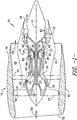
- FIG. 1 illustrates a schematic cross-sectional view of one embodiment of a gas turbine engine 10 (high-bypass type) according to the present disclosure.
- the gas turbine engine 10 may include an aircraft engine.
- the gas turbine engine 10 has an axial longitudinal centerline axis 12 therethrough for reference purposes.
- the gas turbine engine 10 preferably includes a core gas turbine engine generally identified by numeral 14 and a fan section 16 positioned upstream thereof.
- the core engine 14 typically includes a generally tubular outer casing 18 that defines an annular inlet 20.
- the outer casing 18 further encloses and supports a booster 22 for raising the pressure of the air that enters core engine 14 to a first pressure level.
- a high pressure, multi-stage, axial-flow compressor 24 receives pressurized air from the booster 22 and further increases the pressure of the air.
- the compressor 24 includes rotating blades 25 and stationary vanes 27 ( FIGS. 5 and 7 ) that have the function of directing and compressing air within the turbine engine 10.
- the pressurized air flows to a combustor 26, where fuel is injected into the pressurized air stream and ignited to raise the temperature and energy level of the pressurized air.
- the high energy combustion products flow from the combustor 26 to a first (high pressure) turbine 28 for driving the high pressure compressor 24 through a first (high pressure) drive shaft 30, and then to a second (low pressure) turbine 32 for driving the booster 22 and the fan section 16 through a second (low pressure) drive shaft 34 that is coaxial with the first drive shaft 30.
- a first (high pressure) turbine 28 for driving the high pressure compressor 24 through a first (high pressure) drive shaft 30, and then to a second (low pressure) turbine 32 for driving the booster 22 and the fan section 16 through a second (low pressure) drive shaft 34 that is coaxial with the first drive shaft 30.
- the combustion products leave the core engine 14 through an exhaust nozzle 36 to provide at least a portion of the jet propulsive thrust of the engine 10.
- the fan section 16 includes a rotatable, axial-flow fan rotor 38 that is surrounded by an annular fan casing 40.
- fan casing 40 is supported from the core engine 14 by a plurality of substantially radially-extending, circumferentially-spaced outlet guide vanes 42. In this way, the fan casing 40 encloses the fan rotor 38 and the fan rotor blades 44.
- the downstream section 46 of the fan casing 40 extends over an outer portion of the core engine 14 to define a secondary, or bypass, airflow conduit 48 that provides additional jet propulsive thrust.
- an initial airflow enters the gas turbine engine 10 through an inlet 52 to the fan casing 40.
- the airflow passes through the fan blades 44 and splits into a first air flow (represented by arrow 54) that moves through the conduit 48 and a second air flow (represented by arrow 56) which enters the booster 22.
- the pressure of the second compressed airflow 56 is increased and enters the high pressure compressor 24, as represented by arrow 58. After mixing with fuel and being combusted in the combustor 26, the combustion products 60 exit the combustor 26 and flow through the first turbine 28. The combustion products 60 then flow through the second turbine 32 and exit the exhaust nozzle 36 to provide at least a portion of the thrust for the gas turbine engine 10.
- the combustor 26 includes an annular combustion chamber 62 that is coaxial with the longitudinal centerline axis 12, as well as an inlet 64 and an outlet 66. As noted above, the combustor 26 receives an annular stream of pressurized air from a high pressure compressor discharge outlet 69. A portion of this compressor discharge air flows into a mixer (not shown). Fuel is injected from a fuel nozzle 80 to mix with the air and form a fuel-air mixture that is provided to the combustion chamber 62 for combustion. Ignition of the fuel-air mixture is accomplished by a suitable igniter, and the resulting combustion gases 60 flow in an axial direction toward and into an annular, first stage turbine nozzle 72.
- the nozzle 72 is defined by an annular flow channel that includes a plurality of radially-extending, circumferentially-spaced nozzle vanes 74 that turn the gases so that they flow angularly and impinge upon the first stage turbine blades of the first turbine 28.
- the first turbine 28 preferably rotates the high-pressure compressor 24 via the first drive shaft 30, whereas the low-pressure turbine 32 preferably drives the booster 22 and the fan rotor 38 via the second drive shaft 34.
- the combustion chamber 62 is housed within the engine outer casing 18 and fuel is supplied into the combustion chamber 62 by one or more fuel nozzles 80. More specifically, liquid fuel is transported through one or more passageways or conduits within a stem of the fuel nozzle 80.
- foulants accumulate on the engine components. Such accumulation can lead to reduced cooling effectiveness of the components and/or corrosive reaction with the metals and/or coatings of the engine components, as well as fouling and deterioration of aircraft engine components.
- the present disclosure is directed to a system 83 ( FIG. 2 ) and method 100 ( FIG. 3 ) for acoustic cleaning of gas turbine engine components, e.g. such as the components illustrated and described in FIG. 1 .
- the component(s) of the gas turbine engine 10 may include any components of the engine 10 as described herein, including but not limited to the compressor 24, the high-pressure turbine 28, the low-pressure turbine 32, the combustor 26, the combustion chamber 62, one or more nozzles 72, 80, one or more turbine blades or vanes 43, one or more compressor blades 25 or vanes 27, flowpath walls, the booster 22, a turbine shroud, a casing 18 of the gas turbine engine 10, or similar.
- the turbine components to be cleaned by the present system 83 typically have a build-up of foulants accumulated on one or more surfaces thereof, some of which may be difficult to access.
- the acoustic cleaning systems and methods of the present disclosure are particularly useful for cleaning aircraft engines installed on a wing of an aircraft.
- the system 83 includes a hand-held acoustic emitter 84 for producing one or more acoustic waves 88 ( FIG. 6 ) and a controller 93 communicatively coupled to the acoustic emitter 84.
- the acoustic emitter 84 may include a separate local control unit 87 communicatively coupled to a gas turbine controller 93.
- the control unit 87 may be integral with the engine controller 93.
- the acoustic emitter 84 may be directly controlled by the engine controller 93.
- the acoustic emitter 84 includes an acoustic emitter tube 85 configured to direct the acoustic waves 88 towards a cleaning location 89 ( FIGS. 6 and 7 ) of the component(s) of the gas turbine engine 10.
- the acoustic emitter tube 85 may have a diameter and/or length that allow the tube 85 to be easily inserted into an inlet (e.g. inlet 20, 52 or 64) of the engine 10, one or more ports 82 of the engine 10 ( FIG. 5 ), and/or one or more cooling passageways of the component(s) of the engine 10. More specifically, as shown in FIG. 5 , the acoustic emitter tube 85 is illustrated as being inserted into a port of the engine 10.
- the local control unit 87 is configured to control various features and/or operating modes of the emitter 84.
- the acoustic emitter 84 may have an articulating guide 86 located at a distal end of the acoustic emitter tube 85 so as to locate the tube 85 near the cleaning location 89 of the engine component.
- the control unit 87 may be configured to control the articulating guide 86 such that the guide 86 can be selectively located in the vicinity of the target cleaning location 89.
- the guide 86 is configured to direct acoustic waves 88 at a predetermined frequency toward the cleaning location(s) 89 for dispersing the foulants.
- the acoustic emitter 84 may include multiple articulating guides 86, e.g. as shown in FIG. 2 .
- control unit 87 may also include a user interface 91 and an optional key pad that provides a display of the cleaning location(s) 89 to a user.
- the user can view the tube 85 as it emits waves 88 at the cleaning site.
- the user can use the key pad to adjust the articulating guide 86 (as indicated by the dotted lines of FIG. 6 ) to change or adjust the cleaning location 89 as necessary.
- the acoustic emitter 84 may also include a handle configured to assist a user in locating the acoustic emitter tube 85 near the engine component.
- the controller 93 may include one or more processor(s) 94 and associated memory device(s) 95 configured to perform a variety of computer-implemented functions (e.g., performing the methods, steps, calculations and the like and storing relevant data as disclosed herein). Additionally, the controller 93 may also include a communications module 96 to facilitate communications between the controller 93 and the various components of the gas turbine engine 10 or control unit 87.
- the communications module 96 may include a sensor interface 97 (e.g., one or more analog-to-digital converters) to permit signals transmitted from one or more sensors 98, 99 to be converted into signals that can be understood and processed by the processors 94.
- the sensors 98, 99 may be communicatively coupled to the communications module 96 using any suitable means.
- the sensors 98, 99 are coupled to the sensor interface 97 via a wired connection.
- the sensors 98, 99 may be coupled to the sensor interface 97 via a wireless connection, such as by using any suitable wireless communications protocol known in the art.
- the processor 94 may be configured to receive one or more signals from the sensors 98, 99.
- the sensors 98, 99 may include any suitable sensors.
- the system 83 may include at least one emissivity sensor communicatively coupled to the controller 93 and/or the control unit 87.
- the emissivity sensor e.g. sensors 98, 99
- the control unit 87 may be configured to correlate the emissivity with a frequency configured to disperse the foulants, which will be discussed in more detail with reference to FIG. 8 .
- the term "processor” refers not only to integrated circuits referred to in the art as being included in a computer, but also refers to a controller, a microcontroller, a microcomputer, a programmable logic controller (PLC), an application specific integrated circuit, and other programmable circuits.
- the memory device(s) 95 may generally comprise memory element(s) including, but not limited to, computer readable medium (e.g., random access memory (RAM)), computer readable non-volatile medium (e.g., a flash memory), cloud storage, a floppy disk, a compact disc-read only memory (CD-ROM), a magneto-optical disk (MOD), a digital versatile disc (DVD) and/or other suitable memory elements.
- RAM random access memory
- CD-ROM compact disc-read only memory
- MOD magneto-optical disk
- DVD digital versatile disc
- Such memory device(s) 95 may generally be configured to store suitable computer-readable instructions that, when implemented by the processor(s) 94, configure the controller 93 (or control unit 87) to perform various functions including to control the engine and/or the acoustic emitter 84.
- the method 100 includes positioning the acoustic emitter 84 ( FIG. 3 ) near a cleaning location 89 ( FIGS. 5-7 ) or surface of the component of the gas turbine engine 10.
- the cleaning location 89 may be any suitable surface, passageway, or similar of any gas turbine component and is typically characterized by having a build-up of foulants or particulates configured thereon. For example, as shown in FIGS.
- the component includes the compressor 24 and the cleaning location 89 corresponds to an area between a rotating compressor blade 25 and a stationary vane 27.
- the step of positioning the acoustic emitter 84 at a cleaning location 89 of the component of the engine 10 may include inserting an acoustic emitter tube 85 of the acoustic emitter 84 into an inlet (e.g. inlet 20, 52 or 64) of the engine 10, one or more ports 82 of the engine 10, and/or one or more cooling passageways of the component(s) of the engine 10.
- the method 100 is particularly useful for cleaning internal engine components having difficult access.
- the method 100 also includes emitting, via the acoustic emitter 84, one or more acoustic waves 88 at a predetermined frequency towards the cleaning location 89 of the component so as to disperse the foulants.
- the predetermined frequency may range from about 2 hertz (Hz) to about 1500 Hz, more preferably from about 2 Hz to about 800 Hz.
- the step of emitting one or more acoustic waves 88 at the predetermined frequency towards the cleaning location 89 of the component may include providing airflow within the gas turbine engine 10 during emission so as to move the acoustic waves 88 towards the cleaning location 89 of the component.
- the method 100 may include motoring or running the engine 10 during emission of the waves 88 so as to provide airflow that moves the acoustic waves 88 through the component of the gas turbine engine 10.
- the step of emitting one or more acoustic waves at the predetermined frequency towards the cleaning location 89 of the component may include utilizing one or more external pressure sources to provide airflow that moves the acoustic waves 88 through the component of the gas turbine engine 10.
- the external pressure sources may include a fan, a blower, or similar.
- the method 100 may also include rinsing the cleaning location 89.
- the acoustic emitter tube 85 may be configured to deliver cleaning fluids 92 to the cleaning location 89.
- the cleaning fluids are configured to rinse the dispersed foulants from the surface of the component.
- the method 100 may also include determining the predetermined frequency by measuring, via a sensor (e.g. sensors 98, 99), emissivity of the cleaning location 89 and correlating the emissivity with a frequency configured to disperse the foulants.
- emissivity can be correlated to an ideal frequency for dispersing the foulants. More specifically, as shown in Table 1, metals (e.g. aluminum, copper, silver, etc.) typically have a lower emissivity, whereas stones (e.g. asphalt, brick, limestone, marble, plaster, etc.), which is similar in composition to foulants, have a higher emissivity.
- emissivity is the inverse of reflectivity (e.g. as represented by line 106)
- a higher emissivity value is indicative of a higher amount of foulant being present on the engine component.
- low frequency acoustic waves may be provided to the component for dispersing the foulants.
- a lower emissivity value is indicative of a low amount of foulant being present on the engine component, which can be treated with high frequency acoustic waves.
Landscapes
- Engineering & Computer Science (AREA)
- Mechanical Engineering (AREA)
- General Engineering & Computer Science (AREA)
- Chemical & Material Sciences (AREA)
- Combustion & Propulsion (AREA)
- Cleaning In General (AREA)
- Structures Of Non-Positive Displacement Pumps (AREA)
Abstract
Description
- The present subject matter relates generally to gas turbine engines, and more particularly, to acoustic cleaning of on-wing gas turbine engines.
- A gas turbine engine generally includes, in serial flow order, a compressor section, a combustion section, a turbine section and an exhaust section. In operation, air enters an inlet of the compressor section where one or more axial or centrifugal compressors progressively compress the air until it reaches the combustion section. Fuel is mixed with the compressed air and burned within the combustion section to provide combustion gases. The combustion gases are routed from the combustion section through a hot gas path defined within the turbine section and then exhausted from the turbine section via the exhaust section.
- In particular configurations, the turbine section includes, in serial flow order, a high pressure (HP) turbine and a low pressure (LP) turbine. The HP turbine and the LP turbine each include various rotatable turbine components such as turbine rotor blades, rotor disks and retainers, and various stationary turbine components such as stator vanes or nozzles, turbine shrouds, and engine frames. The rotatable and stationary turbine components at least partially define the hot gas path through the turbine section. As the combustion gases flow through the hot gas path, thermal energy is transferred from the combustion gases to the rotatable and stationary turbine components.
- During operation, environmental particulate accumulates on engine components. Such accumulation can lead to reduced cooling effectiveness of the components and/or corrosive reaction with the metals and/or coatings of the engine components, as well as fouling and deterioration of aircraft engine components. Thus, particulate or foulant build-up can lead to premature distress and/or reduced engine life. In addition, substantial accumulation can require the engine to be removed from the aircraft wing, which can time-consuming and expensive.
- As such, on-wing cleaning of gas turbine engines constitutes a significant value proposition as compared to shop-level cleanings. Accordingly, the present disclosure is directed to acoustic cleaning that addresses the aforementioned issues. More specifically, the present disclosure is directed to systems and methods of acoustic cleaning gas turbine engine components that are particularly useful for on-wing cleaning of such components.
- Various aspects and advantages of the invention will be set forth in part in the following description, or may be clear from the description, or may be learned through practice of the invention.
- In one aspect, the present disclosure is directed to a method for cleaning a component of a gas turbine engine. The method includes positioning an acoustic emitter at a cleaning location of the component of the gas turbine engine. For example, the cleaning location may be characterized by having a build-up of foulants. Thus, the method also includes emitting, via the acoustic emitter, one or more acoustic waves at a predetermined frequency towards the cleaning location of the component so as to disperse the foulants.
- In another aspect, the present disclosure is directed to a system for cleaning one or more components of a gas turbine engine. The system includes an acoustic emitter for producing one or more acoustic waves towards the one or more components of the gas turbine engine and a controller communicatively coupled with the acoustic emitter. More specifically, the components typically have a build-up of foulants accumulated on one or more surfaces thereof. Thus, the acoustic emitter is configured to direct the one or more acoustic waves at a predetermined frequency toward the build-up of foulants on the one or more components so as to disperse the foulants. It should also be understood that the system may include any of the additional features as described herein.
- In yet another aspect, the present disclosure is directed to a hand-held acoustic emitter apparatus for cleaning one or more components of a gas turbine engine. The apparatus includes an acoustic emitter tube configured to direct one or more acoustic waves towards a cleaning location of the one or more components of the gas turbine engine. As mentioned, the cleaning location is typically characterized by having a build-up of foulants. Thus, the apparatus also includes an articulating guide located at a distal end of the acoustic emitter tube that is configured to locate the acoustic emitter tube near the cleaning location. Further, the apparatus includes a control unit configured to control the articulating guide. The apparatus may also include a handle configured to assist a user in locating the acoustic emitter tube. It should also be understood that the apparatus may include any of the additional features as described herein.
- Various features, aspects and advantages of the present invention will become better understood with reference to the following description and appended claims. The accompanying drawings, which are incorporated in and constitute a part of this specification, illustrate embodiments of the invention and, together with the description, serve to explain the principles of the invention. In the drawings:
-
FIG. 1 illustrates a schematic cross-sectional view of one embodiment of a gas turbine engine according to the present disclosure; -
FIG. 2 illustrates a schematic diagram of one embodiment of a system configured for acoustic cleaning of one or more gas turbine engine components according to the present disclosure; -
FIG. 3 illustrates a flow diagram of one embodiment of a method for acoustic cleaning one or more components of a gas turbine engine according to the present disclosure; -
FIG. 4 illustrates a block diagram of one embodiment of suitable components that may be included in a gas turbine engine controller or control unit of an acoustic emitter according to the present disclosure; -
FIG. 5 illustrates a partial, cross-sectional view of one embodiment of a compressor of a gas turbine engine, particularly illustrating an acoustic emitter tube of an acoustic emitter being inserted into a port of the compressor according to the present disclosure; -
FIG. 6 illustrates a detailed view of a portion ofFIG. 5 , particularly illustrating an articulating guide at distal end of the acoustic emitter tube emitting acoustic waves towards a cleaning location of a gas turbine engine component according to the present disclosure; -
FIG. 7 illustrates a detailed view of a portion ofFIG. 5 , particularly illustrating an articulating guide at distal end of the acoustic emitter tube emitting cleaning fluid towards a cleaning location of a gas turbine engine component according to the present disclosure; and -
FIG. 8 illustrates a graph of one embodiment of frequency (x-axis) versus emissivity (y-axis) according to the present disclosure. - Reference now will be made in detail to embodiments of the invention, one or more examples of which are illustrated in the drawings. Each example is provided by way of explanation of the invention, not limitation of the invention. In fact, it will be apparent to those skilled in the art that various modifications and variations can be made in the present invention without departing from the scope or spirit of the invention. For instance, features illustrated or described as part of one embodiment can be used with another embodiment to yield a still further embodiment. Thus, it is intended that the present invention covers such modifications and variations as come within the scope of the appended claims and their equivalents.
- As used herein, the terms "first", "second", and "third" may be used interchangeably to distinguish one component from another and are not intended to signify location or importance of the individual components.
- The terms "upstream" and "downstream" refer to the relative direction with respect to fluid flow in a fluid pathway. For example, "upstream" refers to the direction from which the fluid flows, and "downstream" refers to the direction to which the fluid flows.
- The positional terms "proximal" and "distal" are used herein to orient the various components of the acoustic emitter relative to each other and to the gas turbine engine.
- "Distal" refers to the direction that is closest to the gas turbine engine, whereas "proximal" refers to the opposite direction.
- Generally, the present disclosure is directed to systems and methods for cleaning gas turbine engine components using acoustic techniques. More specifically, in one embodiment, the method may include positioning an acoustic emitter near a cleaning location of a component of the gas turbine engine. For example, the cleaning location of the component may be characterized by having a build-up of foulants on a surface thereof. Thus, the method includes emitting, via the acoustic emitter, acoustic waves at a predetermined frequency towards the cleaning location of the component so as to disperse the foulants. As used herein, the term "foulants" generally encompasses any material or particles that can cause fouling or the adhesion of a foreign material or substance onto a surface so as to reduce its functionality. Example foulants may include but are not limited to dirt, dust, mud, particulates, or similar.
- The present disclosure provides various advantages not present in the prior art. For example, gas turbine engines according to present disclosure can be cleaned on-wing, in-situ, and/or off-site. Further, the acoustic cleaning methods of the present disclosure provide simultaneous mechanical and chemical removal of particulate deposits in cooling passageways and/or on external surfaces of gas turbine engine components. In addition, the method of the present disclosure improves cleaning effectiveness and has significant implications for engine time on-wing durability.
- Referring now to the drawings,
FIG. 1 illustrates a schematic cross-sectional view of one embodiment of a gas turbine engine 10 (high-bypass type) according to the present disclosure. More specifically, thegas turbine engine 10 may include an aircraft engine. As shown, thegas turbine engine 10 has an axiallongitudinal centerline axis 12 therethrough for reference purposes. Further, as shown, thegas turbine engine 10 preferably includes a core gas turbine engine generally identified bynumeral 14 and afan section 16 positioned upstream thereof. Thecore engine 14 typically includes a generally tubularouter casing 18 that defines anannular inlet 20. Theouter casing 18 further encloses and supports abooster 22 for raising the pressure of the air that enterscore engine 14 to a first pressure level. A high pressure, multi-stage, axial-flow compressor 24 receives pressurized air from thebooster 22 and further increases the pressure of the air. Thecompressor 24 includesrotating blades 25 and stationary vanes 27 (FIGS. 5 and7 ) that have the function of directing and compressing air within theturbine engine 10. The pressurized air flows to acombustor 26, where fuel is injected into the pressurized air stream and ignited to raise the temperature and energy level of the pressurized air. The high energy combustion products flow from thecombustor 26 to a first (high pressure)turbine 28 for driving thehigh pressure compressor 24 through a first (high pressure) driveshaft 30, and then to a second (low pressure)turbine 32 for driving thebooster 22 and thefan section 16 through a second (low pressure) driveshaft 34 that is coaxial with thefirst drive shaft 30. After driving each of theturbines core engine 14 through anexhaust nozzle 36 to provide at least a portion of the jet propulsive thrust of theengine 10. - The
fan section 16 includes a rotatable, axial-flow fan rotor 38 that is surrounded by anannular fan casing 40. It will be appreciated thatfan casing 40 is supported from thecore engine 14 by a plurality of substantially radially-extending, circumferentially-spaced outlet guide vanes 42. In this way, thefan casing 40 encloses thefan rotor 38 and thefan rotor blades 44. Thedownstream section 46 of thefan casing 40 extends over an outer portion of thecore engine 14 to define a secondary, or bypass,airflow conduit 48 that provides additional jet propulsive thrust. - From a flow standpoint, it will be appreciated that an initial airflow, represented by
arrow 50, enters thegas turbine engine 10 through aninlet 52 to thefan casing 40. The airflow passes through thefan blades 44 and splits into a first air flow (represented by arrow 54) that moves through theconduit 48 and a second air flow (represented by arrow 56) which enters thebooster 22. - The pressure of the second
compressed airflow 56 is increased and enters thehigh pressure compressor 24, as represented byarrow 58. After mixing with fuel and being combusted in thecombustor 26, thecombustion products 60 exit thecombustor 26 and flow through thefirst turbine 28. Thecombustion products 60 then flow through thesecond turbine 32 and exit theexhaust nozzle 36 to provide at least a portion of the thrust for thegas turbine engine 10. - Still referring to
FIG. 1 , thecombustor 26 includes anannular combustion chamber 62 that is coaxial with thelongitudinal centerline axis 12, as well as aninlet 64 and anoutlet 66. As noted above, thecombustor 26 receives an annular stream of pressurized air from a high pressurecompressor discharge outlet 69. A portion of this compressor discharge air flows into a mixer (not shown). Fuel is injected from afuel nozzle 80 to mix with the air and form a fuel-air mixture that is provided to thecombustion chamber 62 for combustion. Ignition of the fuel-air mixture is accomplished by a suitable igniter, and the resultingcombustion gases 60 flow in an axial direction toward and into an annular, firststage turbine nozzle 72. Thenozzle 72 is defined by an annular flow channel that includes a plurality of radially-extending, circumferentially-spacednozzle vanes 74 that turn the gases so that they flow angularly and impinge upon the first stage turbine blades of thefirst turbine 28. As shown inFIG. 1 , thefirst turbine 28 preferably rotates the high-pressure compressor 24 via thefirst drive shaft 30, whereas the low-pressure turbine 32 preferably drives thebooster 22 and thefan rotor 38 via thesecond drive shaft 34. - The
combustion chamber 62 is housed within the engineouter casing 18 and fuel is supplied into thecombustion chamber 62 by one ormore fuel nozzles 80. More specifically, liquid fuel is transported through one or more passageways or conduits within a stem of thefuel nozzle 80. - During operation of the
gas turbine engine 10, foulants accumulate on the engine components. Such accumulation can lead to reduced cooling effectiveness of the components and/or corrosive reaction with the metals and/or coatings of the engine components, as well as fouling and deterioration of aircraft engine components. Thus, the present disclosure is directed to a system 83 (FIG. 2 ) and method 100 (FIG. 3 ) for acoustic cleaning of gas turbine engine components, e.g. such as the components illustrated and described inFIG. 1 . For example, in certain embodiments, the component(s) of thegas turbine engine 10 may include any components of theengine 10 as described herein, including but not limited to thecompressor 24, the high-pressure turbine 28, the low-pressure turbine 32, thecombustor 26, thecombustion chamber 62, one ormore nozzles vanes 43, one ormore compressor blades 25 orvanes 27, flowpath walls, thebooster 22, a turbine shroud, acasing 18 of thegas turbine engine 10, or similar. More specifically, the turbine components to be cleaned by the present system 83 (FIG. 2 ) typically have a build-up of foulants accumulated on one or more surfaces thereof, some of which may be difficult to access. Thus, the acoustic cleaning systems and methods of the present disclosure are particularly useful for cleaning aircraft engines installed on a wing of an aircraft. - Referring specifically to
FIG. 2 , a schematic diagram of one embodiment of thesystem 83 for cleaning one or more components of agas turbine engine 10 according to the present disclosure is illustrated. As shown, thesystem 83 includes a hand-heldacoustic emitter 84 for producing one or more acoustic waves 88 (FIG. 6 ) and acontroller 93 communicatively coupled to theacoustic emitter 84. More specifically, in one embodiment, theacoustic emitter 84 may include a separatelocal control unit 87 communicatively coupled to agas turbine controller 93. Alternatively, thecontrol unit 87 may be integral with theengine controller 93. In additional embodiments, theacoustic emitter 84 may be directly controlled by theengine controller 93. Further, as shown, theacoustic emitter 84 includes anacoustic emitter tube 85 configured to direct theacoustic waves 88 towards a cleaning location 89 (FIGS. 6 and 7 ) of the component(s) of thegas turbine engine 10. For example, theacoustic emitter tube 85 may have a diameter and/or length that allow thetube 85 to be easily inserted into an inlet (e.g.inlet engine 10, one ormore ports 82 of the engine 10 (FIG. 5 ), and/or one or more cooling passageways of the component(s) of theengine 10. More specifically, as shown inFIG. 5 , theacoustic emitter tube 85 is illustrated as being inserted into a port of theengine 10. - In addition, the
local control unit 87 is configured to control various features and/or operating modes of theemitter 84. For example, as shown inFIG. 2 , theacoustic emitter 84 may have an articulatingguide 86 located at a distal end of theacoustic emitter tube 85 so as to locate thetube 85 near the cleaninglocation 89 of the engine component. More specifically, thecontrol unit 87 may be configured to control the articulatingguide 86 such that theguide 86 can be selectively located in the vicinity of thetarget cleaning location 89. As such, theguide 86 is configured to directacoustic waves 88 at a predetermined frequency toward the cleaning location(s) 89 for dispersing the foulants. In additional embodiments, theacoustic emitter 84 may include multiple articulatingguides 86, e.g. as shown inFIG. 2 . - In certain embodiments, the
control unit 87 may also include auser interface 91 and an optional key pad that provides a display of the cleaning location(s) 89 to a user. Thus, the user can view thetube 85 as it emitswaves 88 at the cleaning site. As such, the user can use the key pad to adjust the articulating guide 86 (as indicated by the dotted lines ofFIG. 6 ) to change or adjust the cleaninglocation 89 as necessary. In additional embodiments, theacoustic emitter 84 may also include a handle configured to assist a user in locating theacoustic emitter tube 85 near the engine component. - Referring specifically to
FIG. 4 , there is illustrated a block diagram of one embodiment of suitable components that may be included in thecontroller 93 and/or thecontrol unit 87 according to the present disclosure. As shown, thecontroller 93 may include one or more processor(s) 94 and associated memory device(s) 95 configured to perform a variety of computer-implemented functions (e.g., performing the methods, steps, calculations and the like and storing relevant data as disclosed herein). Additionally, thecontroller 93 may also include acommunications module 96 to facilitate communications between thecontroller 93 and the various components of thegas turbine engine 10 orcontrol unit 87. Further, thecommunications module 96 may include a sensor interface 97 (e.g., one or more analog-to-digital converters) to permit signals transmitted from one ormore sensors processors 94. It should be appreciated that thesensors communications module 96 using any suitable means. For example, as shown inFIG. 4 , thesensors sensor interface 97 via a wired connection. However, in other embodiments, thesensors sensor interface 97 via a wireless connection, such as by using any suitable wireless communications protocol known in the art. As such, theprocessor 94 may be configured to receive one or more signals from thesensors - It should be understood that the
sensors system 83 may include at least one emissivity sensor communicatively coupled to thecontroller 93 and/or thecontrol unit 87. More specifically, the emissivity sensor (e.g. sensors 98, 99) may be configured to detect an emissivity of a surface of the one or more components. Thus, the measured emissivity is configured to give an indication of the amount of foulants on the surface thereof. As such, the control unit 87 (or the controller 93) may be configured to correlate the emissivity with a frequency configured to disperse the foulants, which will be discussed in more detail with reference toFIG. 8 . - As used herein, the term "processor" refers not only to integrated circuits referred to in the art as being included in a computer, but also refers to a controller, a microcontroller, a microcomputer, a programmable logic controller (PLC), an application specific integrated circuit, and other programmable circuits. Additionally, the memory device(s) 95 may generally comprise memory element(s) including, but not limited to, computer readable medium (e.g., random access memory (RAM)), computer readable non-volatile medium (e.g., a flash memory), cloud storage, a floppy disk, a compact disc-read only memory (CD-ROM), a magneto-optical disk (MOD), a digital versatile disc (DVD) and/or other suitable memory elements. Such memory device(s) 95 may generally be configured to store suitable computer-readable instructions that, when implemented by the processor(s) 94, configure the controller 93 (or control unit 87) to perform various functions including to control the engine and/or the
acoustic emitter 84. - Referring now to
FIG. 3 , a flow diagram of one embodiment of amethod 100 for on-wing cleaning one or more components of a gas turbine engine (e.g. such as thegas turbine engine 10 illustrated inFIG. 1 ) is illustrated. As shown at 102, themethod 100 includes positioning the acoustic emitter 84 (FIG. 3 ) near a cleaning location 89 (FIGS. 5-7 ) or surface of the component of thegas turbine engine 10. The cleaninglocation 89 may be any suitable surface, passageway, or similar of any gas turbine component and is typically characterized by having a build-up of foulants or particulates configured thereon. For example, as shown inFIGS. 5-7 , the component includes thecompressor 24 and the cleaninglocation 89 corresponds to an area between arotating compressor blade 25 and astationary vane 27. Thus, as shown, the step of positioning theacoustic emitter 84 at a cleaninglocation 89 of the component of theengine 10 may include inserting anacoustic emitter tube 85 of theacoustic emitter 84 into an inlet (e.g.inlet engine 10, one ormore ports 82 of theengine 10, and/or one or more cooling passageways of the component(s) of theengine 10. Thus, themethod 100 is particularly useful for cleaning internal engine components having difficult access. - Further, as shown in
FIG. 2 , themethod 100 also includes emitting, via theacoustic emitter 84, one or moreacoustic waves 88 at a predetermined frequency towards the cleaninglocation 89 of the component so as to disperse the foulants. In certain embodiments, the predetermined frequency may range from about 2 hertz (Hz) to about 1500 Hz, more preferably from about 2 Hz to about 800 Hz. More specifically, in certain embodiments, the step of emitting one or moreacoustic waves 88 at the predetermined frequency towards the cleaninglocation 89 of the component may include providing airflow within thegas turbine engine 10 during emission so as to move theacoustic waves 88 towards the cleaninglocation 89 of the component. More specifically, themethod 100 may include motoring or running theengine 10 during emission of thewaves 88 so as to provide airflow that moves theacoustic waves 88 through the component of thegas turbine engine 10. Alternatively or in addition, the step of emitting one or more acoustic waves at the predetermined frequency towards the cleaninglocation 89 of the component may include utilizing one or more external pressure sources to provide airflow that moves theacoustic waves 88 through the component of thegas turbine engine 10. For example, in certain embodiments, the external pressure sources may include a fan, a blower, or similar. - After the
acoustic waves 88 are given adequate time to disperse the foulants, themethod 100 may also include rinsing the cleaninglocation 89. For example, as shown inFIG. 7 , theacoustic emitter tube 85 may be configured to deliver cleaningfluids 92 to the cleaninglocation 89. Thus, the cleaning fluids are configured to rinse the dispersed foulants from the surface of the component. - Referring now to
FIG. 8 , themethod 100 may also include determining the predetermined frequency by measuring, via a sensor (e.g. sensors 98, 99), emissivity of the cleaninglocation 89 and correlating the emissivity with a frequency configured to disperse the foulants. For example, as shown in Table 1 and the graph ofFIG. 8 , emissivity can be correlated to an ideal frequency for dispersing the foulants. More specifically, as shown in Table 1, metals (e.g. aluminum, copper, silver, etc.) typically have a lower emissivity, whereas stones (e.g. asphalt, brick, limestone, marble, plaster, etc.), which is similar in composition to foulants, have a higher emissivity. Thus, the presence of foulants results in sensor measurements having a higher emissivity value that can be correlating to an appropriate frequency value for theemitter 84.Material Emissivity Aluminum 0.03 Copper 0.04 Silver 0.02 Asphalt 0.88 Brick 0.90 Limestone 0.92 Marble 0.90 Plaster 0.89 Paint 0.90 - This written description uses examples to disclose the invention, including the preferred mode, and also to enable any person skilled in the art to practice the invention, including making and using any devices or systems and performing any incorporated methods. The patentable scope of the invention is defined by the claims, and may include other examples that occur to those skilled in the art. Such other examples are intended to be within the scope of the claims if they include structural elements that do not differ from the literal language of the claims, or if they include equivalent structural elements with insubstantial differences from the literal languages of the claims.
- Various aspects and embodiments of the present invention are defined by the following numbered clauses:
- 1. A method for cleaning a component of a gas turbine engine, the method comprising:
- positioning an acoustic emitter at a cleaning location of the component of the gas turbine engine, the cleaning location characterized by having a build-up of foulants; and
- emitting, via the acoustic emitter, one or more acoustic waves at a predetermined frequency towards the cleaning location of the component so as to disperse the foulants.
- 2. The method of clause 1, further comprising inserting the acoustic emitter into at least one of an inlet, a port, or a cooling passageway of the component of the gas turbine engine.
- 3. The method of any preceding clause, further comprising determining the predetermined frequency by measuring, via a sensor, emissivity of the cleaning location, and correlating the emissivity with a frequency configured to disperse the foulants.
- 4. The method of any preceding clause, further comprising rinsing the cleaning location, via the acoustic emitter, after emitting the acoustic waves.
- 5. The method of any preceding clause, wherein emitting one or more acoustic waves at the predetermined frequency towards the cleaning location of the component further comprises providing airflow within the gas turbine engine during emission so as to move the acoustic waves towards the cleaning location of the component.
- 6. The method of any preceding clause, wherein the predetermined frequency ranges from about 2 hertz (Hz) to about 1500 Hz.
- 7. The method of any preceding clause, wherein the gas turbine engine comprises an aircraft engine of an aircraft.
- 8. The method of any preceding clause, wherein the aircraft engine is installed on a wing of the aircraft.
- 9. The method of any preceding clause, wherein the one or more components of the gas turbine engine comprise at least one of a compressor, a high-pressure turbine, a low-pressure turbine, a combustor, a combustion chamber, a fuel nozzle, one or more turbine blades, one or more compressor blades, a combustor liner, flowpath walls, a turbine nozzle or vane, a compressor vane, a booster, a turbine shroud, or a casing of the gas turbine engine.
- 10. A system for cleaning one or more components of a gas turbine engine, the system comprising:
- an acoustic emitter for producing one or more acoustic waves for cleaning the one or more components of the gas turbine engine, the one or more components having a build-up of foulants accumulated on a surface thereof; and
- a controller communicatively coupled with the acoustic emitter, the controller configured to control a frequency of the acoustic emitter,
- wherein the acoustic emitter is configured to direct the one or more acoustic waves at a predetermined frequency toward the build-up of foulants on the one or more components so as to disperse the foulants.
- 11. The system of any preceding clause, wherein the acoustic emitter is configured to fit into at least one of an inlet, a port, or a cooling passageway of the component of the gas turbine engine.
- 12. The system of any preceding clause, further comprising one or more pressure sources configured to provide airflow that moves the acoustic waves through the one or more components of the gas turbine engine.
- 13. The system of any preceding clause, wherein the controller is configured to maintain the predetermined frequency of the acoustic emitter between about 2 hertz (Hz) and about 1500 Hz.
- 14. The system of any preceding clause, further comprising at least one emissivity sensor communicatively coupled to the controller, the emissivity sensor configured to detect an emissivity of a surface of the one or more components, the emissivity being indicative of the presence of the foulants on the surface, the controller configured to correlate the emissivity with a frequency configured to disperse the foulants.
- 15. The system of any preceding clause, wherein the gas turbine engine comprises an aircraft engine of an aircraft, wherein the aircraft engine is installed on a wing of the aircraft.
- 16. The system of any preceding clause, wherein the one or more components of the gas turbine engine comprise at least one of a compressor, a high-pressure turbine, a low-pressure turbine, a combustor, a combustion chamber, a fuel nozzle, one or more turbine blades, one or more compressor blades, a combustor liner, flowpath walls, a turbine nozzle or vane, a compressor vane, a booster, a turbine shroud, or a casing of the gas turbine engine.
- 17. A hand-held apparatus for cleaning one or more components of a gas turbine engine, the apparatus comprising:
- an acoustic emitter tube configured to direct one or more acoustic waves towards a cleaning location of the one or more components of the gas turbine engine, the cleaning location characterized by having a build-up of foulants;
- an articulating guide located at a distal end of the acoustic emitter tube, the articulating guide configured to locate the acoustic emitter tube near the cleaning location;
- a control unit configured to control the articulating guide; and
- a handle configured to assist a user in locating the acoustic emitter tube.
- 18. The apparatus of any preceding clause, wherein the acoustic emitter tube of the apparatus is configured to access the cleaning location via at least one of an inlet, a port, or a cooling passageway of the one or more components of the gas turbine engine.
- 19. The apparatus of any preceding clause, wherein the acoustic emitter tube is further configured to deliver cleaning fluids to the cleaning location.
- 20. The apparatus of any preceding clause, wherein the control unit further comprises a user interface configured to display the cleaning location to a user.
Claims (15)
- A method for cleaning a component of a gas turbine engine (10), the method comprising:positioning an acoustic emitter (84) at a cleaning location (89) of the component of the gas turbine engine (10), the cleaning location (89) characterized by having a build-up of foulants; andemitting, via the acoustic emitter (84), one or more acoustic waves (88) at a predetermined frequency towards the cleaning location (89) of the component so as to disperse the foulants.
- The method of claim 1, further comprising inserting the acoustic emitter (84) into at least one of an inlet (20, 52, 64), a port (82), or a cooling passageway of the component of the gas turbine engine (10).
- The method of any preceding claim, further comprising determining the predetermined frequency by measuring, via a sensor (98, 99), emissivity of the cleaning location (89), and correlating the emissivity with a frequency configured to disperse the foulants.
- The method of any preceding claim, further comprising rinsing the cleaning location (89), via the acoustic emitter (84), after emitting the acoustic waves (88).
- The method of any preceding claim, wherein emitting one or more acoustic waves (88) at the predetermined frequency towards the cleaning location (89) of the component further comprises providing airflow within the gas turbine engine (10) during emission so as to move the acoustic waves (88) towards the cleaning location (89) of the component.
- The method of any preceding claim, wherein the predetermined frequency ranges from about 2 hertz (Hz) to about 1500 Hz.
- The method of any preceding claim, wherein the gas turbine engine (10) comprises an aircraft engine of an aircraft.
- The method of claim 7, wherein the aircraft engine is installed on a wing of the aircraft.
- The method of any preceding claim, wherein the one or more components of the gas turbine engine (10) comprise at least one of a compressor (24), a high-pressure turbine (28), a low-pressure turbine (32), a combustor (26), a combustion chamber (62), a fuel nozzle (80), one or more turbine blades, one or more compressor blades (25), a combustor liner, flowpath walls, a turbine nozzle or vane, a compressor vane, a booster (22), a turbine shroud, or a casing of the gas turbine engine (10).
- A system (83) for cleaning one or more components of a gas turbine engine (10), the system (83) comprising:an acoustic emitter (84) for producing one or more acoustic waves (88) for cleaning the one or more components of the gas turbine engine (10), the one or more components having a build-up of foulants accumulated on a surface thereof; anda controller (93) communicatively coupled with the acoustic emitter (84), the controller (93) configured to control a frequency of the acoustic emitter (84),wherein the acoustic emitter (84) is configured to direct the one or more acoustic waves (88) at a predetermined frequency toward the build-up of foulants on the one or more components so as to disperse the foulants.
- The system (83) of claim 10, wherein the acoustic emitter (84) is configured to fit into at least one of an inlet (20, 52, 64), a port (82), or a cooling passageway of the component of the gas turbine engine (10).
- The system (83) of claim 10 or claim 11, further comprising at least one emissivity sensor communicatively coupled to the controller (93), the emissivity sensor configured to detect an emissivity of a surface of the one or more components, the emissivity being indicative of the presence of the foulants on the surface, the controller (93) configured to correlate the emissivity with a frequency configured to disperse the foulants.
- A hand-held apparatus for cleaning one or more components of a gas turbine engine (10), the apparatus comprising:an acoustic emitter (84) tube configured to direct one or more acoustic waves (88) towards a cleaning location (89) of the one or more components of the gas turbine engine (10), the cleaning location (89) characterized by having a build-up of foulants;an articulating guide (86) located at a distal end of the acoustic emitter (84) tube, the articulating guide (86) configured to locate the acoustic emitter (84) tube near the cleaning location (89);a control unit configured to control the articulating guide (86); anda handle configured to assist a user in locating the acoustic emitter (84) tube.
- The apparatus of claim 13, wherein the acoustic emitter (84) tube is further configured to deliver cleaning fluids to the cleaning location (89).
- The apparatus of claim 13 or claim 14, wherein the control unit further comprises a user interface configured to display the cleaning location (89) to a user.
Applications Claiming Priority (1)
| Application Number | Priority Date | Filing Date | Title |
|---|---|---|---|
| US14/970,688 US20170175568A1 (en) | 2015-12-16 | 2015-12-16 | Acoustic Cleaning of Gas Turbine Engine Components |
Publications (3)
| Publication Number | Publication Date |
|---|---|
| EP3238838A2 true EP3238838A2 (en) | 2017-11-01 |
| EP3238838A3 EP3238838A3 (en) | 2018-03-21 |
| EP3238838B1 EP3238838B1 (en) | 2023-11-29 |
Family
ID=57517738
Family Applications (1)
| Application Number | Title | Priority Date | Filing Date |
|---|---|---|---|
| EP16202432.7A Active EP3238838B1 (en) | 2015-12-16 | 2016-12-06 | Acoustic cleaning of gas turbine engine components |
Country Status (6)
| Country | Link |
|---|---|
| US (1) | US20170175568A1 (en) |
| EP (1) | EP3238838B1 (en) |
| JP (1) | JP6374940B2 (en) |
| CN (1) | CN106948883B (en) |
| CA (1) | CA2951095C (en) |
| SG (1) | SG10201609995RA (en) |
Families Citing this family (6)
| Publication number | Priority date | Publication date | Assignee | Title |
|---|---|---|---|---|
| DE102016220437A1 (en) * | 2016-10-19 | 2018-04-19 | Airbus Defence and Space GmbH | Cleaning arrangement for wing leading edges |
| WO2021177269A1 (en) * | 2020-03-04 | 2021-09-10 | 京セラドキュメントソリューションズ株式会社 | Wireless communication device, wireless communication configuration program and wireless communication configuration method |
| CN114308841B (en) * | 2022-03-04 | 2022-05-31 | 山东华业阳光新能源有限公司 | A kind of panel dust removal equipment for solar energy production |
| CN115945462B (en) * | 2022-12-02 | 2023-08-18 | 东莞飞创激光智能装备有限公司 | Laser cleaning aircraft skin real-time monitoring method based on acoustic signal monitoring method |
| CN116946573B (en) * | 2023-09-05 | 2026-03-17 | 济宁华源热电有限公司 | A coal-blocking prevention device for pulverizing systems in thermal power plants |
| CN119175255B (en) * | 2024-11-01 | 2025-10-14 | 太原理工大学 | Ultrasonic cleaning device and method for inner cavity of aircraft engine blades |
Family Cites Families (16)
| Publication number | Priority date | Publication date | Assignee | Title |
|---|---|---|---|---|
| US4302068A (en) * | 1980-03-24 | 1981-11-24 | The United States Of America As Represented By The Secretary Of The Army | Infrared reflex device |
| JPH05149903A (en) * | 1991-11-27 | 1993-06-15 | Toshiba Mach Co Ltd | Method and apparatus for automatically detecting contamination on roll surface |
| DE4341996A1 (en) * | 1993-12-09 | 1995-06-14 | Abb Management Ag | Method of preventing formation of deposits on interior of gas turbine |
| US6412449B1 (en) * | 1998-07-29 | 2002-07-02 | The Babcock & Wilcox Company | Segmented lance assembly |
| US6766813B1 (en) * | 2000-08-01 | 2004-07-27 | Board Of Regents, The University Of Texas System | Apparatus and method for cleaning a wafer |
| US20020148606A1 (en) * | 2001-03-01 | 2002-10-17 | Shunfeng Zheng | Method and apparatus to vibrate a downhole component by use of acoustic resonance |
| US6805140B2 (en) * | 2002-10-15 | 2004-10-19 | United Technologies Corporation | Apparatus and method for cleaning airfoil internal cavities |
| US7126123B1 (en) * | 2003-12-18 | 2006-10-24 | Cessna Aircraft Company | Surface contamination detection method and apparatus |
| US7784739B2 (en) * | 2004-05-26 | 2010-08-31 | The Boeing Company | Detection system and method for ice and other debris |
| WO2009117143A2 (en) * | 2008-03-20 | 2009-09-24 | Hydrochem Industrial Services, Inc. | Automated heat exchanger tube cleaning assembly and system |
| US8733377B2 (en) * | 2010-12-13 | 2014-05-27 | Bha Altair, Llc | Acoustic cleaning device with variable length to compensate application temperature |
| US8603207B2 (en) * | 2011-04-20 | 2013-12-10 | General Electric Company | Acoustic cleaning assembly for use in power generation systems and method of assembling same |
| GB201200876D0 (en) * | 2012-01-19 | 2012-02-29 | Haines David | Acoustic cleaning apparatus |
| US20140207406A1 (en) * | 2013-01-22 | 2014-07-24 | General Electric Company | Self-directed inspection plan |
| US10343193B2 (en) * | 2014-02-24 | 2019-07-09 | The Boeing Company | System and method for surface cleaning |
| US10688536B2 (en) * | 2014-02-24 | 2020-06-23 | The Boeing Company | System and method for surface cleaning |
-
2015
- 2015-12-16 US US14/970,688 patent/US20170175568A1/en not_active Abandoned
-
2016
- 2016-11-28 SG SG10201609995RA patent/SG10201609995RA/en unknown
- 2016-12-02 JP JP2016234616A patent/JP6374940B2/en not_active Expired - Fee Related
- 2016-12-06 EP EP16202432.7A patent/EP3238838B1/en active Active
- 2016-12-08 CA CA2951095A patent/CA2951095C/en not_active Expired - Fee Related
- 2016-12-16 CN CN201611167151.1A patent/CN106948883B/en active Active
Non-Patent Citations (1)
| Title |
|---|
| None |
Also Published As
| Publication number | Publication date |
|---|---|
| CA2951095C (en) | 2019-03-19 |
| CA2951095A1 (en) | 2017-06-16 |
| EP3238838A3 (en) | 2018-03-21 |
| JP6374940B2 (en) | 2018-08-15 |
| JP2017115865A (en) | 2017-06-29 |
| US20170175568A1 (en) | 2017-06-22 |
| CN106948883A (en) | 2017-07-14 |
| CN106948883B (en) | 2020-10-16 |
| EP3238838B1 (en) | 2023-11-29 |
| SG10201609995RA (en) | 2017-07-28 |
Similar Documents
| Publication | Publication Date | Title |
|---|---|---|
| EP3238838B1 (en) | Acoustic cleaning of gas turbine engine components | |
| US10323539B2 (en) | System and method for cleaning gas turbine engine components | |
| EP3213827A1 (en) | Dry detergent and method for cleaning gas turbine engine components | |
| CN113803123B (en) | Inspection and repair tools | |
| US10005111B2 (en) | Turbine engine cleaning systems and methods | |
| JP2017110660A (en) | System and method for in situ cleaning of internal components of gas turbine engine, and related plug assembly | |
| EP3667027B1 (en) | Vane ring for a gas turbine engine and associated method | |
| US10173250B2 (en) | Removing material buildup from an internal surface within a gas turbine engine system | |
| EP3667028B1 (en) | Vane ring with blockage preventer for cooling hole | |
| EP3667026B1 (en) | Vane ring with feed hole blockage preventer and associated method | |
| BR102016029412A2 (en) | METHOD FOR CLEANING A COMPONENT OF A GAS TURBINE MOTOR AND SYSTEM AND PORTABLE APPARATUS FOR CLEANING ONE OR MORE COMPONENTS OF A GAS TURBINE MOTOR | |
| US20160169039A1 (en) | Slots for turbomachine structures |
Legal Events
| Date | Code | Title | Description |
|---|---|---|---|
| PUAI | Public reference made under article 153(3) epc to a published international application that has entered the european phase |
Free format text: ORIGINAL CODE: 0009012 |
|
| STAA | Information on the status of an ep patent application or granted ep patent |
Free format text: STATUS: THE APPLICATION HAS BEEN PUBLISHED |
|
| AK | Designated contracting states |
Kind code of ref document: A2 Designated state(s): AL AT BE BG CH CY CZ DE DK EE ES FI FR GB GR HR HU IE IS IT LI LT LU LV MC MK MT NL NO PL PT RO RS SE SI SK SM TR |
|
| AX | Request for extension of the european patent |
Extension state: BA ME |
|
| PUAL | Search report despatched |
Free format text: ORIGINAL CODE: 0009013 |
|
| AK | Designated contracting states |
Kind code of ref document: A3 Designated state(s): AL AT BE BG CH CY CZ DE DK EE ES FI FR GB GR HR HU IE IS IT LI LT LU LV MC MK MT NL NO PL PT RO RS SE SI SK SM TR |
|
| AX | Request for extension of the european patent |
Extension state: BA ME |
|
| RIC1 | Information provided on ipc code assigned before grant |
Ipc: B08B 7/02 20060101AFI20180213BHEP |
|
| STAA | Information on the status of an ep patent application or granted ep patent |
Free format text: STATUS: REQUEST FOR EXAMINATION WAS MADE |
|
| 17P | Request for examination filed |
Effective date: 20180921 |
|
| RBV | Designated contracting states (corrected) |
Designated state(s): AL AT BE BG CH CY CZ DE DK EE ES FI FR GB GR HR HU IE IS IT LI LT LU LV MC MK MT NL NO PL PT RO RS SE SI SK SM TR |
|
| STAA | Information on the status of an ep patent application or granted ep patent |
Free format text: STATUS: EXAMINATION IS IN PROGRESS |
|
| 17Q | First examination report despatched |
Effective date: 20210819 |
|
| GRAP | Despatch of communication of intention to grant a patent |
Free format text: ORIGINAL CODE: EPIDOSNIGR1 |
|
| STAA | Information on the status of an ep patent application or granted ep patent |
Free format text: STATUS: GRANT OF PATENT IS INTENDED |
|
| INTG | Intention to grant announced |
Effective date: 20230626 |
|
| GRAS | Grant fee paid |
Free format text: ORIGINAL CODE: EPIDOSNIGR3 |
|
| GRAA | (expected) grant |
Free format text: ORIGINAL CODE: 0009210 |
|
| STAA | Information on the status of an ep patent application or granted ep patent |
Free format text: STATUS: THE PATENT HAS BEEN GRANTED |
|
| AK | Designated contracting states |
Kind code of ref document: B1 Designated state(s): AL AT BE BG CH CY CZ DE DK EE ES FI FR GB GR HR HU IE IS IT LI LT LU LV MC MK MT NL NO PL PT RO RS SE SI SK SM TR |
|
| P01 | Opt-out of the competence of the unified patent court (upc) registered |
Effective date: 20231024 |
|
| REG | Reference to a national code |
Ref country code: GB Ref legal event code: FG4D |
|
| REG | Reference to a national code |
Ref country code: CH Ref legal event code: EP |
|
| REG | Reference to a national code |
Ref country code: DE Ref legal event code: R096 Ref document number: 602016084369 Country of ref document: DE |
|
| REG | Reference to a national code |
Ref country code: IE Ref legal event code: FG4D |
|
| REG | Reference to a national code |
Ref country code: LT Ref legal event code: MG9D |
|
| REG | Reference to a national code |
Ref country code: NL Ref legal event code: MP Effective date: 20231129 |
|
| PG25 | Lapsed in a contracting state [announced via postgrant information from national office to epo] |
Ref country code: GR Free format text: LAPSE BECAUSE OF FAILURE TO SUBMIT A TRANSLATION OF THE DESCRIPTION OR TO PAY THE FEE WITHIN THE PRESCRIBED TIME-LIMIT Effective date: 20240301 |
|
| PG25 | Lapsed in a contracting state [announced via postgrant information from national office to epo] |
Ref country code: IS Free format text: LAPSE BECAUSE OF FAILURE TO SUBMIT A TRANSLATION OF THE DESCRIPTION OR TO PAY THE FEE WITHIN THE PRESCRIBED TIME-LIMIT Effective date: 20240329 |
|
| PG25 | Lapsed in a contracting state [announced via postgrant information from national office to epo] |
Ref country code: LT Free format text: LAPSE BECAUSE OF FAILURE TO SUBMIT A TRANSLATION OF THE DESCRIPTION OR TO PAY THE FEE WITHIN THE PRESCRIBED TIME-LIMIT Effective date: 20231129 |
|
| PG25 | Lapsed in a contracting state [announced via postgrant information from national office to epo] |
Ref country code: ES Free format text: LAPSE BECAUSE OF FAILURE TO SUBMIT A TRANSLATION OF THE DESCRIPTION OR TO PAY THE FEE WITHIN THE PRESCRIBED TIME-LIMIT Effective date: 20231129 |
|
| PG25 | Lapsed in a contracting state [announced via postgrant information from national office to epo] |
Ref country code: LT Free format text: LAPSE BECAUSE OF FAILURE TO SUBMIT A TRANSLATION OF THE DESCRIPTION OR TO PAY THE FEE WITHIN THE PRESCRIBED TIME-LIMIT Effective date: 20231129 Ref country code: IS Free format text: LAPSE BECAUSE OF FAILURE TO SUBMIT A TRANSLATION OF THE DESCRIPTION OR TO PAY THE FEE WITHIN THE PRESCRIBED TIME-LIMIT Effective date: 20240329 Ref country code: GR Free format text: LAPSE BECAUSE OF FAILURE TO SUBMIT A TRANSLATION OF THE DESCRIPTION OR TO PAY THE FEE WITHIN THE PRESCRIBED TIME-LIMIT Effective date: 20240301 Ref country code: ES Free format text: LAPSE BECAUSE OF FAILURE TO SUBMIT A TRANSLATION OF THE DESCRIPTION OR TO PAY THE FEE WITHIN THE PRESCRIBED TIME-LIMIT Effective date: 20231129 Ref country code: BG Free format text: LAPSE BECAUSE OF FAILURE TO SUBMIT A TRANSLATION OF THE DESCRIPTION OR TO PAY THE FEE WITHIN THE PRESCRIBED TIME-LIMIT Effective date: 20240229 |
|
| REG | Reference to a national code |
Ref country code: AT Ref legal event code: MK05 Ref document number: 1635583 Country of ref document: AT Kind code of ref document: T Effective date: 20231129 |
|
| PG25 | Lapsed in a contracting state [announced via postgrant information from national office to epo] |
Ref country code: NL Free format text: LAPSE BECAUSE OF FAILURE TO SUBMIT A TRANSLATION OF THE DESCRIPTION OR TO PAY THE FEE WITHIN THE PRESCRIBED TIME-LIMIT Effective date: 20231129 |
|
| PG25 | Lapsed in a contracting state [announced via postgrant information from national office to epo] |
Ref country code: SE Free format text: LAPSE BECAUSE OF FAILURE TO SUBMIT A TRANSLATION OF THE DESCRIPTION OR TO PAY THE FEE WITHIN THE PRESCRIBED TIME-LIMIT Effective date: 20231129 Ref country code: RS Free format text: LAPSE BECAUSE OF FAILURE TO SUBMIT A TRANSLATION OF THE DESCRIPTION OR TO PAY THE FEE WITHIN THE PRESCRIBED TIME-LIMIT Effective date: 20231129 Ref country code: PL Free format text: LAPSE BECAUSE OF FAILURE TO SUBMIT A TRANSLATION OF THE DESCRIPTION OR TO PAY THE FEE WITHIN THE PRESCRIBED TIME-LIMIT Effective date: 20231129 Ref country code: NO Free format text: LAPSE BECAUSE OF FAILURE TO SUBMIT A TRANSLATION OF THE DESCRIPTION OR TO PAY THE FEE WITHIN THE PRESCRIBED TIME-LIMIT Effective date: 20240229 Ref country code: NL Free format text: LAPSE BECAUSE OF FAILURE TO SUBMIT A TRANSLATION OF THE DESCRIPTION OR TO PAY THE FEE WITHIN THE PRESCRIBED TIME-LIMIT Effective date: 20231129 Ref country code: LV Free format text: LAPSE BECAUSE OF FAILURE TO SUBMIT A TRANSLATION OF THE DESCRIPTION OR TO PAY THE FEE WITHIN THE PRESCRIBED TIME-LIMIT Effective date: 20231129 Ref country code: HR Free format text: LAPSE BECAUSE OF FAILURE TO SUBMIT A TRANSLATION OF THE DESCRIPTION OR TO PAY THE FEE WITHIN THE PRESCRIBED TIME-LIMIT Effective date: 20231129 |
|
| PG25 | Lapsed in a contracting state [announced via postgrant information from national office to epo] |
Ref country code: DK Free format text: LAPSE BECAUSE OF FAILURE TO SUBMIT A TRANSLATION OF THE DESCRIPTION OR TO PAY THE FEE WITHIN THE PRESCRIBED TIME-LIMIT Effective date: 20231129 |
|
| PG25 | Lapsed in a contracting state [announced via postgrant information from national office to epo] |
Ref country code: CZ Free format text: LAPSE BECAUSE OF FAILURE TO SUBMIT A TRANSLATION OF THE DESCRIPTION OR TO PAY THE FEE WITHIN THE PRESCRIBED TIME-LIMIT Effective date: 20231129 Ref country code: AT Free format text: LAPSE BECAUSE OF FAILURE TO SUBMIT A TRANSLATION OF THE DESCRIPTION OR TO PAY THE FEE WITHIN THE PRESCRIBED TIME-LIMIT Effective date: 20231129 |
|
| PG25 | Lapsed in a contracting state [announced via postgrant information from national office to epo] |
Ref country code: SK Free format text: LAPSE BECAUSE OF FAILURE TO SUBMIT A TRANSLATION OF THE DESCRIPTION OR TO PAY THE FEE WITHIN THE PRESCRIBED TIME-LIMIT Effective date: 20231129 |
|
| PG25 | Lapsed in a contracting state [announced via postgrant information from national office to epo] |
Ref country code: SM Free format text: LAPSE BECAUSE OF FAILURE TO SUBMIT A TRANSLATION OF THE DESCRIPTION OR TO PAY THE FEE WITHIN THE PRESCRIBED TIME-LIMIT Effective date: 20231129 Ref country code: SK Free format text: LAPSE BECAUSE OF FAILURE TO SUBMIT A TRANSLATION OF THE DESCRIPTION OR TO PAY THE FEE WITHIN THE PRESCRIBED TIME-LIMIT Effective date: 20231129 Ref country code: RO Free format text: LAPSE BECAUSE OF FAILURE TO SUBMIT A TRANSLATION OF THE DESCRIPTION OR TO PAY THE FEE WITHIN THE PRESCRIBED TIME-LIMIT Effective date: 20231129 Ref country code: IT Free format text: LAPSE BECAUSE OF FAILURE TO SUBMIT A TRANSLATION OF THE DESCRIPTION OR TO PAY THE FEE WITHIN THE PRESCRIBED TIME-LIMIT Effective date: 20231129 Ref country code: EE Free format text: LAPSE BECAUSE OF FAILURE TO SUBMIT A TRANSLATION OF THE DESCRIPTION OR TO PAY THE FEE WITHIN THE PRESCRIBED TIME-LIMIT Effective date: 20231129 Ref country code: DK Free format text: LAPSE BECAUSE OF FAILURE TO SUBMIT A TRANSLATION OF THE DESCRIPTION OR TO PAY THE FEE WITHIN THE PRESCRIBED TIME-LIMIT Effective date: 20231129 Ref country code: CZ Free format text: LAPSE BECAUSE OF FAILURE TO SUBMIT A TRANSLATION OF THE DESCRIPTION OR TO PAY THE FEE WITHIN THE PRESCRIBED TIME-LIMIT Effective date: 20231129 Ref country code: AT Free format text: LAPSE BECAUSE OF FAILURE TO SUBMIT A TRANSLATION OF THE DESCRIPTION OR TO PAY THE FEE WITHIN THE PRESCRIBED TIME-LIMIT Effective date: 20231129 |
|
| REG | Reference to a national code |
Ref country code: CH Ref legal event code: PL |
|
| PG25 | Lapsed in a contracting state [announced via postgrant information from national office to epo] |
Ref country code: PT Free format text: LAPSE BECAUSE OF FAILURE TO SUBMIT A TRANSLATION OF THE DESCRIPTION OR TO PAY THE FEE WITHIN THE PRESCRIBED TIME-LIMIT Effective date: 20240401 |
|
| PG25 | Lapsed in a contracting state [announced via postgrant information from national office to epo] |
Ref country code: LU Free format text: LAPSE BECAUSE OF NON-PAYMENT OF DUE FEES Effective date: 20231206 |
|
| PG25 | Lapsed in a contracting state [announced via postgrant information from national office to epo] |
Ref country code: MC Free format text: LAPSE BECAUSE OF FAILURE TO SUBMIT A TRANSLATION OF THE DESCRIPTION OR TO PAY THE FEE WITHIN THE PRESCRIBED TIME-LIMIT Effective date: 20231129 |
|
| REG | Reference to a national code |
Ref country code: BE Ref legal event code: MM Effective date: 20231231 |
|
| PG25 | Lapsed in a contracting state [announced via postgrant information from national office to epo] |
Ref country code: PT Free format text: LAPSE BECAUSE OF FAILURE TO SUBMIT A TRANSLATION OF THE DESCRIPTION OR TO PAY THE FEE WITHIN THE PRESCRIBED TIME-LIMIT Effective date: 20240401 Ref country code: MC Free format text: LAPSE BECAUSE OF FAILURE TO SUBMIT A TRANSLATION OF THE DESCRIPTION OR TO PAY THE FEE WITHIN THE PRESCRIBED TIME-LIMIT Effective date: 20231129 Ref country code: LU Free format text: LAPSE BECAUSE OF NON-PAYMENT OF DUE FEES Effective date: 20231206 |
|
| REG | Reference to a national code |
Ref country code: DE Ref legal event code: R097 Ref document number: 602016084369 Country of ref document: DE |
|
| PLBE | No opposition filed within time limit |
Free format text: ORIGINAL CODE: 0009261 |
|
| STAA | Information on the status of an ep patent application or granted ep patent |
Free format text: STATUS: NO OPPOSITION FILED WITHIN TIME LIMIT |
|
| REG | Reference to a national code |
Ref country code: IE Ref legal event code: MM4A |
|
| PG25 | Lapsed in a contracting state [announced via postgrant information from national office to epo] |
Ref country code: IE Free format text: LAPSE BECAUSE OF NON-PAYMENT OF DUE FEES Effective date: 20231206 |
|
| PG25 | Lapsed in a contracting state [announced via postgrant information from national office to epo] |
Ref country code: BE Free format text: LAPSE BECAUSE OF NON-PAYMENT OF DUE FEES Effective date: 20231231 |
|
| PG25 | Lapsed in a contracting state [announced via postgrant information from national office to epo] |
Ref country code: CH Free format text: LAPSE BECAUSE OF NON-PAYMENT OF DUE FEES Effective date: 20231231 |
|
| PG25 | Lapsed in a contracting state [announced via postgrant information from national office to epo] |
Ref country code: SI Free format text: LAPSE BECAUSE OF FAILURE TO SUBMIT A TRANSLATION OF THE DESCRIPTION OR TO PAY THE FEE WITHIN THE PRESCRIBED TIME-LIMIT Effective date: 20231129 |
|
| PG25 | Lapsed in a contracting state [announced via postgrant information from national office to epo] |
Ref country code: SI Free format text: LAPSE BECAUSE OF FAILURE TO SUBMIT A TRANSLATION OF THE DESCRIPTION OR TO PAY THE FEE WITHIN THE PRESCRIBED TIME-LIMIT Effective date: 20231129 Ref country code: IE Free format text: LAPSE BECAUSE OF NON-PAYMENT OF DUE FEES Effective date: 20231206 Ref country code: CH Free format text: LAPSE BECAUSE OF NON-PAYMENT OF DUE FEES Effective date: 20231231 Ref country code: BE Free format text: LAPSE BECAUSE OF NON-PAYMENT OF DUE FEES Effective date: 20231231 |
|
| 26N | No opposition filed |
Effective date: 20240830 |
|
| PG25 | Lapsed in a contracting state [announced via postgrant information from national office to epo] |
Ref country code: FI Free format text: LAPSE BECAUSE OF FAILURE TO SUBMIT A TRANSLATION OF THE DESCRIPTION OR TO PAY THE FEE WITHIN THE PRESCRIBED TIME-LIMIT Effective date: 20231129 |
|
| PG25 | Lapsed in a contracting state [announced via postgrant information from national office to epo] |
Ref country code: CY Free format text: LAPSE BECAUSE OF FAILURE TO SUBMIT A TRANSLATION OF THE DESCRIPTION OR TO PAY THE FEE WITHIN THE PRESCRIBED TIME-LIMIT; INVALID AB INITIO Effective date: 20161206 |
|
| PG25 | Lapsed in a contracting state [announced via postgrant information from national office to epo] |
Ref country code: HU Free format text: LAPSE BECAUSE OF FAILURE TO SUBMIT A TRANSLATION OF THE DESCRIPTION OR TO PAY THE FEE WITHIN THE PRESCRIBED TIME-LIMIT; INVALID AB INITIO Effective date: 20161206 |
|
| PG25 | Lapsed in a contracting state [announced via postgrant information from national office to epo] |
Ref country code: TR Free format text: LAPSE BECAUSE OF FAILURE TO SUBMIT A TRANSLATION OF THE DESCRIPTION OR TO PAY THE FEE WITHIN THE PRESCRIBED TIME-LIMIT Effective date: 20231129 |
|
| PGFP | Annual fee paid to national office [announced via postgrant information from national office to epo] |
Ref country code: DE Payment date: 20251126 Year of fee payment: 10 |
|
| PGFP | Annual fee paid to national office [announced via postgrant information from national office to epo] |
Ref country code: GB Payment date: 20251120 Year of fee payment: 10 |
|
| PGFP | Annual fee paid to national office [announced via postgrant information from national office to epo] |
Ref country code: FR Payment date: 20251119 Year of fee payment: 10 |