EP3238766B1 - Airtightness-detecting intermediate pipe assembly - Google Patents
Airtightness-detecting intermediate pipe assembly Download PDFInfo
- Publication number
- EP3238766B1 EP3238766B1 EP15871516.9A EP15871516A EP3238766B1 EP 3238766 B1 EP3238766 B1 EP 3238766B1 EP 15871516 A EP15871516 A EP 15871516A EP 3238766 B1 EP3238766 B1 EP 3238766B1
- Authority
- EP
- European Patent Office
- Prior art keywords
- septum
- joint
- circuit
- lumen
- partition plate
- Prior art date
- Legal status (The legal status is an assumption and is not a legal conclusion. Google has not performed a legal analysis and makes no representation as to the accuracy of the status listed.)
- Active
Links
Images
Classifications
-
- A—HUMAN NECESSITIES
- A61—MEDICAL OR VETERINARY SCIENCE; HYGIENE
- A61M—DEVICES FOR INTRODUCING MEDIA INTO, OR ONTO, THE BODY; DEVICES FOR TRANSDUCING BODY MEDIA OR FOR TAKING MEDIA FROM THE BODY; DEVICES FOR PRODUCING OR ENDING SLEEP OR STUPOR
- A61M16/00—Devices for influencing the respiratory system of patients by gas treatment, e.g. ventilators; Tracheal tubes
- A61M16/08—Bellows; Connecting tubes ; Water traps; Patient circuits
-
- G—PHYSICS
- G01—MEASURING; TESTING
- G01M—TESTING STATIC OR DYNAMIC BALANCE OF MACHINES OR STRUCTURES; TESTING OF STRUCTURES OR APPARATUS, NOT OTHERWISE PROVIDED FOR
- G01M3/00—Investigating fluid-tightness of structures
- G01M3/02—Investigating fluid-tightness of structures by using fluid or vacuum
- G01M3/26—Investigating fluid-tightness of structures by using fluid or vacuum by measuring rate of loss or gain of fluid, e.g. by pressure-responsive devices, by flow detectors
Definitions
- the present invention relates to the field of medical equipment technology, and more specifically to an airtightness-detecting bi-lumen breathing circuit septum assembly.
- Mechanical ventilation equipment is an important form of medical equipment, which supplies patients with the oxygen they require.
- Mechanical ventilation equipment usually consists of a breathing mask, a medical ventilator (comprising parts such as an oxygen supply machine and an anaesthetic machine) and a bi-lumen breathing circuit which connects the breathing mask and ventilator of the type disclosed in the applicant's prior Utility Model No. CN 203 852 686U .
- the sufficient airtightness of the bi-lumen breathing circuit as a channel for conveying gas is the determinant of effective gas transport when the ventilator is in use.
- the inner cavity of the bi-lumen breathing circuit contains a septum which partitions the circuit into two channels for transporting different types of gases.
- the aim of the present invention is to overcome the shortcomings of the prior art described above, and to provide an airtightness-detecting bi-lumen breathing circuit septum assembly which can detect the airtightness of the circuit wall and septum, thereby ensuring safety.
- An bi-lumen breathing circuit septum assembly comprising: a first joint for connecting a breathing mask and a second joint for connecting a ventilator, with said first joint and said second joint being connected by a bi-lumen breathing circuit which is a bendable circuit body used to transport gases, inside the cavity of which is contained a septum which partitions said bi-lumen breathing circuit into a first and second channel which are mutually isolated, wherein the assembly is a bi-lumen breathing circuit septum assembly further comprising: a partition plate for partitioning the cavity of said first joint into two mutually isolated sections; and a connection structure located at the partition plate for its connection with said septum, with one end of said septum being connected to said connection structure; and a testing stopper insertable into said first joint to block either the first or second channel.
- connection structure is a recessed groove located on said partition plate, with the said septum being slotted into said recessed groove.
- the one end on which each of the said first and second joints connect to said circuit body is the connected end, with said connected end being inserted into the circuit body, and with said partition plate being located within the cavity of the said connected end.
- said partition plate partitions the inner cavity of the said connected end into two equal sections.
- said connected end is equipped with grooves for the installation of sealing rings.
- the connecting point of said first joint with said circuit body and that of said second joint with said circuit body are each sealed and protected with an airtight plastic layer.
- Said airtight plastic layer is wrapped around the corresponding surfaces of the said sealing rings.
- said circuit body is a corrugated pipe.
- the present invention provides an airtightness-detecting bi-lumen breathing circuit septum assembly which contains, in the inner cavity of the first joint, a partition plate with a connection structure.
- the connection structures on the septum and partition plate are connected, therefore partitioning the circuit body into two mutually isolated channels.
- the leak test can then therefore be conducted on said septum when one of the said partitioned channels are blocked, thereby eliminating the risk involved in using traditional bi-lumen breathing circuits arising from the inability to detect leakage of the septum therein.
- the invention therefore makes it safer to use bi-lumen breathing circuits.
- the present invention offers an airtightness-detecting bi-lumen breathing circuit septum assembly, comprising: a first joint (11) for connecting a breathing mask, and a second joint (12) for connecting a ventilator, with said first joint (11) and said second joint (12) being connected by a bi-lumen breathing circuit (13) which comprises a bendable circuit body (131) for transporting gases, inside the cavity of which is contained a septum (134) which partitions the said bi-lumen breathing circuit body (131) into a first (132) and second channel (133) which are mutually isolated, a partition plate (14) to partition the cavity of said first joint (11) into two mutually isolated sections, and a connection structure (141) provided at the partition plate (14) for its connection with said septum (134), with one end of said septum (134) being connected to said connection structure (141).
- Such a design allows, in the course of manufacture and assembly, one end of the first joint (11) to be inserted into the circuit body (131), connecting one end of the septum (134) with the connection structure (141). Accordingly, the partition plate (14) and septum (134) together separate the whole circuit body (131) into mutually isolated first (132) and second (133) channels for the transport of different gases.
- the gases transported through the first (132) and the second (133) channels cannot be mixed, and it is therefore crucial that the septum (134) is airtight, in order to ensure the reliable transport of gases.
- the insertion of a partition plate (14) and the connection structure (141) which is used for connection with the septum (134) within the first joint (11) allows the complete mutual isolation of the first (132) and second channels (133) when the septum (134) and partition plate (14) are connected.
- the testing stopper (2) can then be inserted into the first joint (11) to block either the first (132) or second channel (133) by contact with the upper and lower hard walls, after which the second joint (12) can be connected with a ventilator or anaesthetic machine (3).
- the ventilator or anaesthetic machine (3) is then used to draw gas of a certain pressure into the channel over a continuous period of time. If the reading of the pressure gauge (31) on the ventilator or anaesthetic machine (3) does not change, the septum (134) is shown to have no leaking and is thus airtight. If the reading of the pressure gauge (31) changes, the septum (134) is then shown to not be airtight, and therefore unusable. In this manner, a test can be conducted on the airtightness of the septum (134), while a septum (134) which causes leaking may then be screened out to ensure safety when using bi-lumen breathing circuits.
- This embodiment of the present invention provides an airtight-detecting bi-lumen breathing circuit septum assembly which contains in the inner cavity of the first joint (11) a partition plate (14) with a connection structure (141) on said partition plate (14) which connects said connection structure (141) with one end of the septum (134) in order to allow the septum (134) to partition the inner cavity of the circuit body (131) into two mutually isolated channels.
- a test can be conducted on the airtightness of the septum (134), screening out bi-lumen breathing circuits containing septum (134) with leakages, preventing said bi-lumen breathing circuits (13) with leaking septums (134) from being used, thereby providing for safe use.
- connection structure (141) is a recessed groove set on the partition plate (14), with the orientation of said recessed groove being the same as that of the long side of the partition plate (14), and said septum (134) being slotted into said recessed groove.
- the mode of connection between the septum (134) and the recessed groove is referred to as interference fit.
- a sealed plastic layer is laid between the two, ensuring their connectedness and that the point of connection remains airtight and firmly sealed.
- the respective ends connecting the circuit body (131) with the first (11) and second (12) joints are referred to as the connected end (111), with the other end of the first joint (11) being connected to the breathing mask.
- the connected end (111) is inserted into the circuit body (131), and the septum (14) located within the cavity of the connected end (111).
- the septum (14) partitions the connected end (111) into two equal sections. In this case, the septum (14) partitions the connected end (111) into two equal sections to achieve the required specification for gas transport.
- a sealing groove (113) for the installation of a sealing ring (112) is located at the connection end (111).
- a sealing ring (112) is fitted on the sealing groove (113), with airtightness being further ensured by the connection end (111) fitting into the circuit body (131) with the sealing ring (112) properly fitted.
- the airtightness of the connection end may be subject to impact created by external forces under certain circumstances when it is in use, including when connected to the breathing mask and the ventilator, or when it does not remain stationery when in use.
- the connecting point between said first joint (11) and said circuit body (131) and that of said second joint (12) with said circuit body (131) are each sealed and protected with an airtight plastic layer (114). Said airtight plastic layer (114) is wrapped around the corresponding surfaces of said sealing rings (112).
- This configuration allows sealing to first be carried out with the sealing ring (112), then by inserting rubber or soft plastic by means of injection moulding or vulcanisation in the gaps of the connection ends, thus filling up the gap between the first joint (11) and the circuit body (131) and the gap between the second joint (12) and the circuit body (131) and welding the two parts into one and adhering to the sealing ring (112), forming into a reinforced airtight plastic layer (114), the reliability and strength of the airtightness of the connecting points can be ensured. A certain degree of external force will then be made tolerable so that the reinforced connection does not loosen, thus ensuring the reliable transport of gases.
- the circuit body (131) is a corrugated pipe, as its concertinaed surface allows for bending and deformation without damage.
Landscapes
- Health & Medical Sciences (AREA)
- Heart & Thoracic Surgery (AREA)
- Life Sciences & Earth Sciences (AREA)
- Emergency Medicine (AREA)
- Pulmonology (AREA)
- Engineering & Computer Science (AREA)
- Anesthesiology (AREA)
- Veterinary Medicine (AREA)
- Biomedical Technology (AREA)
- Hematology (AREA)
- Public Health (AREA)
- Animal Behavior & Ethology (AREA)
- General Health & Medical Sciences (AREA)
- Physics & Mathematics (AREA)
- General Physics & Mathematics (AREA)
- Examining Or Testing Airtightness (AREA)
- Respiratory Apparatuses And Protective Means (AREA)
Description
- The present invention relates to the field of medical equipment technology, and more specifically to an airtightness-detecting bi-lumen breathing circuit septum assembly.
- Mechanical ventilation equipment is an important form of medical equipment, which supplies patients with the oxygen they require. Mechanical ventilation equipment usually consists of a breathing mask, a medical ventilator (comprising parts such as an oxygen supply machine and an anaesthetic machine) and a bi-lumen breathing circuit which connects the breathing mask and ventilator of the type disclosed in the applicant's prior Utility Model No.
CN 203 852 686U . The sufficient airtightness of the bi-lumen breathing circuit as a channel for conveying gas is the determinant of effective gas transport when the ventilator is in use. The inner cavity of the bi-lumen breathing circuit contains a septum which partitions the circuit into two channels for transporting different types of gases. Gas leaking from the septum leads to the mixing of different gases, which may endanger the health of the patient given the different reactions that can result from the transport of different gases. It is therefore necessary to conduct an airtightness test for the septum inside the bi-lumen breathing circuit. There is, however, no way to detect the airtightness of the septum in any existing bi-lumen breathing circuits, presenting a safety risk to the users. - The aim of the present invention is to overcome the shortcomings of the prior art described above, and to provide an airtightness-detecting bi-lumen breathing circuit septum assembly which can detect the airtightness of the circuit wall and septum, thereby ensuring safety.
- The present invention is realised by the following means: An bi-lumen breathing circuit septum assembly, comprising: a first joint for connecting a breathing mask and a second joint for connecting a ventilator, with said first joint and said second joint being connected by a bi-lumen breathing circuit which is a bendable circuit body used to transport gases, inside the cavity of which is contained a septum which partitions said bi-lumen breathing circuit into a first and second channel which are mutually isolated, wherein the assembly is a bi-lumen breathing circuit septum assembly further comprising: a partition plate for partitioning the cavity of said first joint into two mutually isolated sections; and a connection structure located at the partition plate for its connection with said septum, with one end of said septum being connected to said connection structure; and a testing stopper insertable into said first joint to block either the first or second channel.
- Specifically, said connection structure is a recessed groove located on said partition plate, with the said septum being slotted into said recessed groove.
- Specifically, the one end on which each of the said first and second joints connect to said circuit body is the connected end, with said connected end being inserted into the circuit body, and with said partition plate being located within the cavity of the said connected end.
- Specifically, said partition plate partitions the inner cavity of the said connected end into two equal sections.
- Specifically, said connected end is equipped with grooves for the installation of sealing rings.
- Specifically, the connecting point of said first joint with said circuit body and that of said second joint with said circuit body are each sealed and protected with an airtight plastic layer. Said airtight plastic layer is wrapped around the corresponding surfaces of the said sealing rings.
- Preferably, said circuit body is a corrugated pipe.
- The present invention provides an airtightness-detecting bi-lumen breathing circuit septum assembly which contains, in the inner cavity of the first joint, a partition plate with a connection structure. In this way, the connection structures on the septum and partition plate are connected, therefore partitioning the circuit body into two mutually isolated channels. The leak test can then therefore be conducted on said septum when one of the said partitioned channels are blocked, thereby eliminating the risk involved in using traditional bi-lumen breathing circuits arising from the inability to detect leakage of the septum therein. The invention therefore makes it safer to use bi-lumen breathing circuits.
-
-
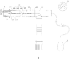
Figure 1 is a schematic diagram showing the airtightness-detecting bi-lumen breathing circuit septum assembly provided in an embodiment of the present invention. -
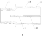
Figure 2 is a diagram showing the first joint of the airtightness-detecting bi-lumen breathing circuit septum assembly provided in an embodiment of the present invention. - To further illustrate the aim of the present invention, its technical solution and advantages, the drawings will be referred to in conjunction with the embodiments hereafter to give a detailed description of the present invention. It should be appreciated that the embodiments of the present invention are merely provided for the purposes of illustration, with the present invention not being limited to the specific embodiments described below.
- As indicated in
Figures 1 and2 , the present invention offers an airtightness-detecting bi-lumen breathing circuit septum assembly, comprising: a first joint (11) for connecting a breathing mask, and a second joint (12) for connecting a ventilator, with said first joint (11) and said second joint (12) being connected by a bi-lumen breathing circuit (13) which comprises a bendable circuit body (131) for transporting gases, inside the cavity of which is contained a septum (134) which partitions the said bi-lumen breathing circuit body (131) into a first (132) and second channel (133) which are mutually isolated, a partition plate (14) to partition the cavity of said first joint (11) into two mutually isolated sections, and a connection structure (141) provided at the partition plate (14) for its connection with said septum (134), with one end of said septum (134) being connected to said connection structure (141). Such a design allows, in the course of manufacture and assembly, one end of the first joint (11) to be inserted into the circuit body (131), connecting one end of the septum (134) with the connection structure (141). Accordingly, the partition plate (14) and septum (134) together separate the whole circuit body (131) into mutually isolated first (132) and second (133) channels for the transport of different gases. The gases transported through the first (132) and the second (133) channels cannot be mixed, and it is therefore crucial that the septum (134) is airtight, in order to ensure the reliable transport of gases. Furthermore, in the present embodiment, the insertion of a partition plate (14) and the connection structure (141) which is used for connection with the septum (134) within the first joint (11) allows the complete mutual isolation of the first (132) and second channels (133) when the septum (134) and partition plate (14) are connected. When a test is to be conducted, after blocking the first joint (11), and completing the leak test for the circuit body (131), the airtightness of the septum (134) can be detected. The testing stopper (2) can then be inserted into the first joint (11) to block either the first (132) or second channel (133) by contact with the upper and lower hard walls, after which the second joint (12) can be connected with a ventilator or anaesthetic machine (3). The ventilator or anaesthetic machine (3) is then used to draw gas of a certain pressure into the channel over a continuous period of time. If the reading of the pressure gauge (31) on the ventilator or anaesthetic machine (3) does not change, the septum (134) is shown to have no leaking and is thus airtight. If the reading of the pressure gauge (31) changes, the septum (134) is then shown to not be airtight, and therefore unusable. In this manner, a test can be conducted on the airtightness of the septum (134), while a septum (134) which causes leaking may then be screened out to ensure safety when using bi-lumen breathing circuits. - This embodiment of the present inventionprovides an airtight-detecting bi-lumen breathing circuit septum assembly which contains in the inner cavity of the first joint (11) a partition plate (14) with a connection structure (141) on said partition plate (14) which connects said connection structure (141) with one end of the septum (134) in order to allow the septum (134) to partition the inner cavity of the circuit body (131) into two mutually isolated channels. In this case, by blocking one of the channels and allowing gases to enter from the other end, a test can be conducted on the airtightness of the septum (134), screening out bi-lumen breathing circuits containing septum (134) with leakages, preventing said bi-lumen breathing circuits (13) with leaking septums (134) from being used, thereby providing for safe use.
- Specifically, as shown in
Figures 1 and2 , the connection structure (141) is a recessed groove set on the partition plate (14), with the orientation of said recessed groove being the same as that of the long side of the partition plate (14), and said septum (134) being slotted into said recessed groove. The mode of connection between the septum (134) and the recessed groove is referred to as interference fit. Additionally, as the septum (134) is slotted into the recessed groove, a sealed plastic layer is laid between the two, ensuring their connectedness and that the point of connection remains airtight and firmly sealed. - Specifically, as shown in
Figures 1 and2 , the respective ends connecting the circuit body (131) with the first (11) and second (12) joints are referred to as the connected end (111), with the other end of the first joint (11) being connected to the breathing mask. The connected end (111) is inserted into the circuit body (131), and the septum (14) located within the cavity of the connected end (111). Moreover, the septum (14) partitions the connected end (111) into two equal sections. In this case, the septum (14) partitions the connected end (111) into two equal sections to achieve the required specification for gas transport. - Specifically, as shown in
Figures 1 and2 , to ensure the airtightness of the connection and to avoid leaking between the bi-lumen breathing circuit (13) and the first joint (11), a sealing groove (113) for the installation of a sealing ring (112) is located at the connection end (111). A sealing ring (112) is fitted on the sealing groove (113), with airtightness being further ensured by the connection end (111) fitting into the circuit body (131) with the sealing ring (112) properly fitted. - Specifically, as shown in
Figures 1 and2 , the airtightness of the connection end may be subject to impact created by external forces under certain circumstances when it is in use, including when connected to the breathing mask and the ventilator, or when it does not remain stationery when in use. To ensure the airtightness of the connecting points and to avoid leakages, the connecting point between said first joint (11) and said circuit body (131) and that of said second joint (12) with said circuit body (131) are each sealed and protected with an airtight plastic layer (114). Said airtight plastic layer (114) is wrapped around the corresponding surfaces of said sealing rings (112). This configuration allows sealing to first be carried out with the sealing ring (112), then by inserting rubber or soft plastic by means of injection moulding or vulcanisation in the gaps of the connection ends, thus filling up the gap between the first joint (11) and the circuit body (131) and the gap between the second joint (12) and the circuit body (131) and welding the two parts into one and adhering to the sealing ring (112), forming into a reinforced airtight plastic layer (114), the reliability and strength of the airtightness of the connecting points can be ensured. A certain degree of external force will then be made tolerable so that the reinforced connection does not loosen, thus ensuring the reliable transport of gases. - Preferably, the circuit body (131) is a corrugated pipe, as its concertinaed surface allows for bending and deformation without damage.
- The above description gives only the preferred embodiments of the present invention and is not used to limit the scope of protection thereof. All the modifications, equivalent replacements or improvements in the scope of the present inventionshall be included in the scope of protection of the present invention.
Claims (7)
- A bi-lumen breathing circuit septum assembly, comprising: a first joint (11) for connecting a breathing mask and a second joint (12) for connecting a ventilator, with said first joint and said second joint being connected by a bi-lumen breathing circuit (13) which is a bendable circuit body (131) used to transport gases, inside the cavity of which is contained a septum (134) which partitions said bi-lumen breathing circuit (13) into a first and second channel (132, 133) which are mutually isolated, further comprising: a partition plate (14) for partitioning the cavity of said first joint (11) into two mutually isolated sections; and a connection structure (114) located at the partition plate (14) for its connection with said septum (134), with one end of said septum (134) being connected to said connection structure (114); characterised in that
the assembly further comprises a testing stopper (2) insertable into said first joint (11) to block either the first or second channel (132, 133) to allow detection of airtightness of the bi-lumen circuit septum. - The bi-lumen breathing circuit septum assembly according to claim 1, characterised by said connection structure (114) being a recessed groove located on said partition plate (14), with said septum (134) slotting into said recessed groove.
- The bi-lumen breathing circuit septum assembly according to claim 1, characterised by the one end on which each of said first and second joints (11, 12) is connected to said circuit body being the connected end, and said connected end being inserted into the circuit body (131), with the partition plate (14) located within the cavity of the said connected end.
- The bi-lumen breathing circuit septum assembly according to claim 3, characterised by said partition plate (14) partitioning the cavity of said connection end into two equal sections.
- The bi-lumen breathing circuit septum assembly according to claim 3, characterised by a sealing groove (113) being provided on said connection end for the installation of sealing rings (112).
- The bi-lumen breathing circuit septum assembly according to claim 5, characterised by the connecting point of said first joint (11) and said circuit body (131), and the connecting point of said second joint (12) and said circuit body (131) each being sealed and protected with an airtight plastic layer, with said airtight plastic layer being wrapped around the corresponding surfaces of said sealing rings (112).
- The bi-lumen breathing circuit septum assembly according to any of claims 1-6, characterised by said circuit body being a corrugated pipe (134).
Applications Claiming Priority (2)
| Application Number | Priority Date | Filing Date | Title |
|---|---|---|---|
| CN201420826657.9U CN204428568U (en) | 2014-12-23 | 2014-12-23 | Assembly is in charge of in salable detection |
| PCT/CN2015/076021 WO2016101438A1 (en) | 2014-12-23 | 2015-04-08 | Airtightness-detecting intermediate pipe assembly |
Publications (3)
| Publication Number | Publication Date |
|---|---|
| EP3238766A1 EP3238766A1 (en) | 2017-11-01 |
| EP3238766A4 EP3238766A4 (en) | 2018-01-17 |
| EP3238766B1 true EP3238766B1 (en) | 2018-12-05 |
Family
ID=53596495
Family Applications (1)
| Application Number | Title | Priority Date | Filing Date |
|---|---|---|---|
| EP15871516.9A Active EP3238766B1 (en) | 2014-12-23 | 2015-04-08 | Airtightness-detecting intermediate pipe assembly |
Country Status (3)
| Country | Link |
|---|---|
| EP (1) | EP3238766B1 (en) |
| CN (1) | CN204428568U (en) |
| WO (1) | WO2016101438A1 (en) |
Families Citing this family (1)
| Publication number | Priority date | Publication date | Assignee | Title |
|---|---|---|---|---|
| CN107063589B (en) * | 2017-06-23 | 2023-04-25 | 苏彬诚 | Vacuum pipeline sealing detection device |
Family Cites Families (6)
| Publication number | Priority date | Publication date | Assignee | Title |
|---|---|---|---|---|
| CA2004930C (en) * | 1989-12-08 | 1996-04-02 | John Richard Sikora | Anaesthetic and respirator breathing circuit device |
| DE4113707C1 (en) * | 1991-04-26 | 1992-10-29 | Draegerwerk Ag, 2400 Luebeck, De | |
| CN201586307U (en) * | 2009-12-28 | 2010-09-22 | 艾青 | Double-lumen bronchial catheter with adjustable lumens |
| CN202777348U (en) * | 2012-07-31 | 2013-03-13 | 深圳安维森实业有限公司 | Breathing tube and breathing apparatus |
| US9919122B2 (en) * | 2012-12-03 | 2018-03-20 | Vyaire Medical Consumables Llc | Fluid trap apparatus |
| CN203852686U (en) * | 2014-04-24 | 2014-10-01 | 深圳安维森实业有限公司 | Breathing tube, breathing tube assembly and breathing apparatus |
-
2014
- 2014-12-23 CN CN201420826657.9U patent/CN204428568U/en not_active Expired - Lifetime
-
2015
- 2015-04-08 EP EP15871516.9A patent/EP3238766B1/en active Active
- 2015-04-08 WO PCT/CN2015/076021 patent/WO2016101438A1/en not_active Ceased
Non-Patent Citations (1)
| Title |
|---|
| None * |
Also Published As
| Publication number | Publication date |
|---|---|
| EP3238766A1 (en) | 2017-11-01 |
| CN204428568U (en) | 2015-07-01 |
| EP3238766A4 (en) | 2018-01-17 |
| WO2016101438A1 (en) | 2016-06-30 |
Similar Documents
| Publication | Publication Date | Title |
|---|---|---|
| US9289588B2 (en) | Connector against contrary flowing for medical treatment | |
| CN106413799A (en) | System for closed transfer of fluids with a locking member | |
| CN106132474B (en) | Medical connector | |
| SG11201908927TA (en) | Connection equipment and equipment connector | |
| NZ630695A (en) | Nasal mask system | |
| US20170065788A1 (en) | Medical joint and check valve module thereof | |
| CN105873559A (en) | System with adapter for closed transfer of fluids | |
| EP3359861B2 (en) | Connection clamping device | |
| EP3238766B1 (en) | Airtightness-detecting intermediate pipe assembly | |
| US20150021863A1 (en) | Mutiple-Leak Proof Sealiing System | |
| CN106168312A (en) | A kind of dismountable adapter | |
| CN103016876B (en) | Quick connector and anti-falling structure thereof | |
| CN204554142U (en) | Hydraulic pipeline repairs joint | |
| CN204364655U (en) | A kind of positive pressure connector | |
| EP2345448B1 (en) | Ventilator device or anaesthetic device | |
| CN103477195A (en) | Double closure for double-chamber differential pressure measurement device | |
| CN104455846A (en) | Flange connection sealing device | |
| CN105953004A (en) | Fire hose coupling connector | |
| WO2015078203A1 (en) | Laryngeal mask balloon pressure detection device and laryngeal mask device | |
| CN204879195U (en) | Device for connecting be used for PVC reinforced pipe | |
| CN204619101U (en) | For connecting the swivel joint of face shield and comprising the anesthetic gas machine pipeline of this joint | |
| CN207161943U (en) | It is a kind of to insert positive threeway entirely | |
| CN204213541U (en) | A kind of new tube joint | |
| CN203824595U (en) | Multi-diameter variable-aperture flow probe | |
| CN106139341B (en) | A kind of triplate line and its detection method for breathing circuit |
Legal Events
| Date | Code | Title | Description |
|---|---|---|---|
| STAA | Information on the status of an ep patent application or granted ep patent |
Free format text: STATUS: THE INTERNATIONAL PUBLICATION HAS BEEN MADE |
|
| PUAI | Public reference made under article 153(3) epc to a published international application that has entered the european phase |
Free format text: ORIGINAL CODE: 0009012 |
|
| STAA | Information on the status of an ep patent application or granted ep patent |
Free format text: STATUS: REQUEST FOR EXAMINATION WAS MADE |
|
| 17P | Request for examination filed |
Effective date: 20170217 |
|
| AK | Designated contracting states |
Kind code of ref document: A1 Designated state(s): AL AT BE BG CH CY CZ DE DK EE ES FI FR GB GR HR HU IE IS IT LI LT LU LV MC MK MT NL NO PL PT RO RS SE SI SK SM TR |
|
| AX | Request for extension of the european patent |
Extension state: BA ME |
|
| RIC1 | Information provided on ipc code assigned before grant |
Ipc: A61M 16/08 20060101ALI20171205BHEP Ipc: G01M 3/26 20060101ALI20171205BHEP Ipc: A61M 16/00 20060101AFI20171205BHEP |
|
| A4 | Supplementary search report drawn up and despatched |
Effective date: 20171214 |
|
| DAV | Request for validation of the european patent (deleted) | ||
| DAX | Request for extension of the european patent (deleted) | ||
| GRAP | Despatch of communication of intention to grant a patent |
Free format text: ORIGINAL CODE: EPIDOSNIGR1 |
|
| STAA | Information on the status of an ep patent application or granted ep patent |
Free format text: STATUS: GRANT OF PATENT IS INTENDED |
|
| GRAS | Grant fee paid |
Free format text: ORIGINAL CODE: EPIDOSNIGR3 |
|
| INTG | Intention to grant announced |
Effective date: 20180924 |
|
| GRAA | (expected) grant |
Free format text: ORIGINAL CODE: 0009210 |
|
| STAA | Information on the status of an ep patent application or granted ep patent |
Free format text: STATUS: THE PATENT HAS BEEN GRANTED |
|
| AK | Designated contracting states |
Kind code of ref document: B1 Designated state(s): AL AT BE BG CH CY CZ DE DK EE ES FI FR GB GR HR HU IE IS IT LI LT LU LV MC MK MT NL NO PL PT RO RS SE SI SK SM TR |
|
| RAP1 | Party data changed (applicant data changed or rights of an application transferred) |
Owner name: SHENZHEN ENVISEN INDUSTRY CO., LIMITED |
|
| REG | Reference to a national code |
Ref country code: GB Ref legal event code: FG4D |
|
| RIN1 | Information on inventor provided before grant (corrected) |
Inventor name: LU, YUFEI |
|
| REG | Reference to a national code |
Ref country code: CH Ref legal event code: EP |
|
| REG | Reference to a national code |
Ref country code: AT Ref legal event code: REF Ref document number: 1072289 Country of ref document: AT Kind code of ref document: T Effective date: 20181215 |
|
| REG | Reference to a national code |
Ref country code: IE Ref legal event code: FG4D |
|
| REG | Reference to a national code |
Ref country code: DE Ref legal event code: R096 Ref document number: 602015021106 Country of ref document: DE |
|
| REG | Reference to a national code |
Ref country code: NL Ref legal event code: MP Effective date: 20181205 |
|
| REG | Reference to a national code |
Ref country code: AT Ref legal event code: MK05 Ref document number: 1072289 Country of ref document: AT Kind code of ref document: T Effective date: 20181205 |
|
| REG | Reference to a national code |
Ref country code: LT Ref legal event code: MG4D |
|
| PG25 | Lapsed in a contracting state [announced via postgrant information from national office to epo] |
Ref country code: AT Free format text: LAPSE BECAUSE OF FAILURE TO SUBMIT A TRANSLATION OF THE DESCRIPTION OR TO PAY THE FEE WITHIN THE PRESCRIBED TIME-LIMIT Effective date: 20181205 Ref country code: LV Free format text: LAPSE BECAUSE OF FAILURE TO SUBMIT A TRANSLATION OF THE DESCRIPTION OR TO PAY THE FEE WITHIN THE PRESCRIBED TIME-LIMIT Effective date: 20181205 Ref country code: ES Free format text: LAPSE BECAUSE OF FAILURE TO SUBMIT A TRANSLATION OF THE DESCRIPTION OR TO PAY THE FEE WITHIN THE PRESCRIBED TIME-LIMIT Effective date: 20181205 Ref country code: LT Free format text: LAPSE BECAUSE OF FAILURE TO SUBMIT A TRANSLATION OF THE DESCRIPTION OR TO PAY THE FEE WITHIN THE PRESCRIBED TIME-LIMIT Effective date: 20181205 Ref country code: NO Free format text: LAPSE BECAUSE OF FAILURE TO SUBMIT A TRANSLATION OF THE DESCRIPTION OR TO PAY THE FEE WITHIN THE PRESCRIBED TIME-LIMIT Effective date: 20190305 Ref country code: FI Free format text: LAPSE BECAUSE OF FAILURE TO SUBMIT A TRANSLATION OF THE DESCRIPTION OR TO PAY THE FEE WITHIN THE PRESCRIBED TIME-LIMIT Effective date: 20181205 Ref country code: BG Free format text: LAPSE BECAUSE OF FAILURE TO SUBMIT A TRANSLATION OF THE DESCRIPTION OR TO PAY THE FEE WITHIN THE PRESCRIBED TIME-LIMIT Effective date: 20190305 Ref country code: HR Free format text: LAPSE BECAUSE OF FAILURE TO SUBMIT A TRANSLATION OF THE DESCRIPTION OR TO PAY THE FEE WITHIN THE PRESCRIBED TIME-LIMIT Effective date: 20181205 |
|
| PG25 | Lapsed in a contracting state [announced via postgrant information from national office to epo] |
Ref country code: RS Free format text: LAPSE BECAUSE OF FAILURE TO SUBMIT A TRANSLATION OF THE DESCRIPTION OR TO PAY THE FEE WITHIN THE PRESCRIBED TIME-LIMIT Effective date: 20181205 Ref country code: SE Free format text: LAPSE BECAUSE OF FAILURE TO SUBMIT A TRANSLATION OF THE DESCRIPTION OR TO PAY THE FEE WITHIN THE PRESCRIBED TIME-LIMIT Effective date: 20181205 Ref country code: AL Free format text: LAPSE BECAUSE OF FAILURE TO SUBMIT A TRANSLATION OF THE DESCRIPTION OR TO PAY THE FEE WITHIN THE PRESCRIBED TIME-LIMIT Effective date: 20181205 Ref country code: GR Free format text: LAPSE BECAUSE OF FAILURE TO SUBMIT A TRANSLATION OF THE DESCRIPTION OR TO PAY THE FEE WITHIN THE PRESCRIBED TIME-LIMIT Effective date: 20190306 |
|
| PG25 | Lapsed in a contracting state [announced via postgrant information from national office to epo] |
Ref country code: NL Free format text: LAPSE BECAUSE OF FAILURE TO SUBMIT A TRANSLATION OF THE DESCRIPTION OR TO PAY THE FEE WITHIN THE PRESCRIBED TIME-LIMIT Effective date: 20181205 |
|
| PG25 | Lapsed in a contracting state [announced via postgrant information from national office to epo] |
Ref country code: PL Free format text: LAPSE BECAUSE OF FAILURE TO SUBMIT A TRANSLATION OF THE DESCRIPTION OR TO PAY THE FEE WITHIN THE PRESCRIBED TIME-LIMIT Effective date: 20181205 Ref country code: CZ Free format text: LAPSE BECAUSE OF FAILURE TO SUBMIT A TRANSLATION OF THE DESCRIPTION OR TO PAY THE FEE WITHIN THE PRESCRIBED TIME-LIMIT Effective date: 20181205 Ref country code: IT Free format text: LAPSE BECAUSE OF FAILURE TO SUBMIT A TRANSLATION OF THE DESCRIPTION OR TO PAY THE FEE WITHIN THE PRESCRIBED TIME-LIMIT Effective date: 20181205 Ref country code: PT Free format text: LAPSE BECAUSE OF FAILURE TO SUBMIT A TRANSLATION OF THE DESCRIPTION OR TO PAY THE FEE WITHIN THE PRESCRIBED TIME-LIMIT Effective date: 20190405 |
|
| PG25 | Lapsed in a contracting state [announced via postgrant information from national office to epo] |
Ref country code: IS Free format text: LAPSE BECAUSE OF FAILURE TO SUBMIT A TRANSLATION OF THE DESCRIPTION OR TO PAY THE FEE WITHIN THE PRESCRIBED TIME-LIMIT Effective date: 20190405 Ref country code: RO Free format text: LAPSE BECAUSE OF FAILURE TO SUBMIT A TRANSLATION OF THE DESCRIPTION OR TO PAY THE FEE WITHIN THE PRESCRIBED TIME-LIMIT Effective date: 20181205 Ref country code: EE Free format text: LAPSE BECAUSE OF FAILURE TO SUBMIT A TRANSLATION OF THE DESCRIPTION OR TO PAY THE FEE WITHIN THE PRESCRIBED TIME-LIMIT Effective date: 20181205 Ref country code: SM Free format text: LAPSE BECAUSE OF FAILURE TO SUBMIT A TRANSLATION OF THE DESCRIPTION OR TO PAY THE FEE WITHIN THE PRESCRIBED TIME-LIMIT Effective date: 20181205 Ref country code: SK Free format text: LAPSE BECAUSE OF FAILURE TO SUBMIT A TRANSLATION OF THE DESCRIPTION OR TO PAY THE FEE WITHIN THE PRESCRIBED TIME-LIMIT Effective date: 20181205 |
|
| REG | Reference to a national code |
Ref country code: DE Ref legal event code: R097 Ref document number: 602015021106 Country of ref document: DE |
|
| PLBE | No opposition filed within time limit |
Free format text: ORIGINAL CODE: 0009261 |
|
| STAA | Information on the status of an ep patent application or granted ep patent |
Free format text: STATUS: NO OPPOSITION FILED WITHIN TIME LIMIT |
|
| PG25 | Lapsed in a contracting state [announced via postgrant information from national office to epo] |
Ref country code: DK Free format text: LAPSE BECAUSE OF FAILURE TO SUBMIT A TRANSLATION OF THE DESCRIPTION OR TO PAY THE FEE WITHIN THE PRESCRIBED TIME-LIMIT Effective date: 20181205 Ref country code: SI Free format text: LAPSE BECAUSE OF FAILURE TO SUBMIT A TRANSLATION OF THE DESCRIPTION OR TO PAY THE FEE WITHIN THE PRESCRIBED TIME-LIMIT Effective date: 20181205 |
|
| 26N | No opposition filed |
Effective date: 20190906 |
|
| REG | Reference to a national code |
Ref country code: CH Ref legal event code: PL |
|
| REG | Reference to a national code |
Ref country code: BE Ref legal event code: MM Effective date: 20190430 |
|
| PG25 | Lapsed in a contracting state [announced via postgrant information from national office to epo] |
Ref country code: LU Free format text: LAPSE BECAUSE OF NON-PAYMENT OF DUE FEES Effective date: 20190408 Ref country code: MC Free format text: LAPSE BECAUSE OF FAILURE TO SUBMIT A TRANSLATION OF THE DESCRIPTION OR TO PAY THE FEE WITHIN THE PRESCRIBED TIME-LIMIT Effective date: 20181205 |
|
| PG25 | Lapsed in a contracting state [announced via postgrant information from national office to epo] |
Ref country code: CH Free format text: LAPSE BECAUSE OF NON-PAYMENT OF DUE FEES Effective date: 20190430 Ref country code: LI Free format text: LAPSE BECAUSE OF NON-PAYMENT OF DUE FEES Effective date: 20190430 |
|
| PG25 | Lapsed in a contracting state [announced via postgrant information from national office to epo] |
Ref country code: BE Free format text: LAPSE BECAUSE OF NON-PAYMENT OF DUE FEES Effective date: 20190430 |
|
| PG25 | Lapsed in a contracting state [announced via postgrant information from national office to epo] |
Ref country code: TR Free format text: LAPSE BECAUSE OF FAILURE TO SUBMIT A TRANSLATION OF THE DESCRIPTION OR TO PAY THE FEE WITHIN THE PRESCRIBED TIME-LIMIT Effective date: 20181205 |
|
| PG25 | Lapsed in a contracting state [announced via postgrant information from national office to epo] |
Ref country code: IE Free format text: LAPSE BECAUSE OF NON-PAYMENT OF DUE FEES Effective date: 20190408 |
|
| PG25 | Lapsed in a contracting state [announced via postgrant information from national office to epo] |
Ref country code: CY Free format text: LAPSE BECAUSE OF FAILURE TO SUBMIT A TRANSLATION OF THE DESCRIPTION OR TO PAY THE FEE WITHIN THE PRESCRIBED TIME-LIMIT Effective date: 20181205 |
|
| PG25 | Lapsed in a contracting state [announced via postgrant information from national office to epo] |
Ref country code: HU Free format text: LAPSE BECAUSE OF FAILURE TO SUBMIT A TRANSLATION OF THE DESCRIPTION OR TO PAY THE FEE WITHIN THE PRESCRIBED TIME-LIMIT; INVALID AB INITIO Effective date: 20150408 Ref country code: MT Free format text: LAPSE BECAUSE OF FAILURE TO SUBMIT A TRANSLATION OF THE DESCRIPTION OR TO PAY THE FEE WITHIN THE PRESCRIBED TIME-LIMIT Effective date: 20181205 |
|
| PG25 | Lapsed in a contracting state [announced via postgrant information from national office to epo] |
Ref country code: MK Free format text: LAPSE BECAUSE OF FAILURE TO SUBMIT A TRANSLATION OF THE DESCRIPTION OR TO PAY THE FEE WITHIN THE PRESCRIBED TIME-LIMIT Effective date: 20181205 |
|
| P01 | Opt-out of the competence of the unified patent court (upc) registered |
Effective date: 20240305 |
|
| PGFP | Annual fee paid to national office [announced via postgrant information from national office to epo] |
Ref country code: GB Payment date: 20250318 Year of fee payment: 11 |
|
| PGFP | Annual fee paid to national office [announced via postgrant information from national office to epo] |
Ref country code: DE Payment date: 20250428 Year of fee payment: 11 |
|
| PGFP | Annual fee paid to national office [announced via postgrant information from national office to epo] |
Ref country code: FR Payment date: 20250424 Year of fee payment: 11 |