EP3238651B1 - Real-time fusion of anatomical ultrasound information and radiation delivery information for radiation therapies - Google Patents
Real-time fusion of anatomical ultrasound information and radiation delivery information for radiation therapies Download PDFInfo
- Publication number
- EP3238651B1 EP3238651B1 EP17170971.0A EP17170971A EP3238651B1 EP 3238651 B1 EP3238651 B1 EP 3238651B1 EP 17170971 A EP17170971 A EP 17170971A EP 3238651 B1 EP3238651 B1 EP 3238651B1
- Authority
- EP
- European Patent Office
- Prior art keywords
- radiation
- ultrasound
- fiducials
- delivery
- fiducial
- Prior art date
- Legal status (The legal status is an assumption and is not a legal conclusion. Google has not performed a legal analysis and makes no representation as to the accuracy of the status listed.)
- Active
Links
Images

Classifications
-
- A—HUMAN NECESSITIES
- A61—MEDICAL OR VETERINARY SCIENCE; HYGIENE
- A61N—ELECTROTHERAPY; MAGNETOTHERAPY; RADIATION THERAPY; ULTRASOUND THERAPY
- A61N5/00—Radiation therapy
- A61N5/10—X-ray therapy; Gamma-ray therapy; Particle-irradiation therapy
- A61N5/103—Treatment planning systems
- A61N5/1039—Treatment planning systems using functional images, e.g. PET or MRI
-
- A—HUMAN NECESSITIES
- A61—MEDICAL OR VETERINARY SCIENCE; HYGIENE
- A61N—ELECTROTHERAPY; MAGNETOTHERAPY; RADIATION THERAPY; ULTRASOUND THERAPY
- A61N5/00—Radiation therapy
- A61N5/10—X-ray therapy; Gamma-ray therapy; Particle-irradiation therapy
- A61N5/103—Treatment planning systems
- A61N5/1038—Treatment planning systems taking into account previously administered plans applied to the same patient, i.e. adaptive radiotherapy
-
- A—HUMAN NECESSITIES
- A61—MEDICAL OR VETERINARY SCIENCE; HYGIENE
- A61B—DIAGNOSIS; SURGERY; IDENTIFICATION
- A61B6/00—Apparatus for radiation diagnosis, e.g. combined with radiation therapy equipment
- A61B6/02—Devices for diagnosis sequentially in different planes; Stereoscopic radiation diagnosis
- A61B6/03—Computerised tomographs
- A61B6/032—Transmission computed tomography [CT]
-
- A—HUMAN NECESSITIES
- A61—MEDICAL OR VETERINARY SCIENCE; HYGIENE
- A61B—DIAGNOSIS; SURGERY; IDENTIFICATION
- A61B8/00—Diagnosis using ultrasonic, sonic or infrasonic waves
- A61B8/08—Detecting organic movements or changes, e.g. tumours, cysts, swellings
- A61B8/0833—Detecting organic movements or changes, e.g. tumours, cysts, swellings involving detecting or locating foreign bodies or organic structures
-
- A—HUMAN NECESSITIES
- A61—MEDICAL OR VETERINARY SCIENCE; HYGIENE
- A61B—DIAGNOSIS; SURGERY; IDENTIFICATION
- A61B8/00—Diagnosis using ultrasonic, sonic or infrasonic waves
- A61B8/44—Constructional features of the ultrasonic, sonic or infrasonic diagnostic device
- A61B8/4483—Constructional features of the ultrasonic, sonic or infrasonic diagnostic device characterised by features of the ultrasound transducer
-
- A—HUMAN NECESSITIES
- A61—MEDICAL OR VETERINARY SCIENCE; HYGIENE
- A61B—DIAGNOSIS; SURGERY; IDENTIFICATION
- A61B8/00—Diagnosis using ultrasonic, sonic or infrasonic waves
- A61B8/48—Diagnostic techniques
- A61B8/483—Diagnostic techniques involving the acquisition of a 3D volume of data
-
- A—HUMAN NECESSITIES
- A61—MEDICAL OR VETERINARY SCIENCE; HYGIENE
- A61N—ELECTROTHERAPY; MAGNETOTHERAPY; RADIATION THERAPY; ULTRASOUND THERAPY
- A61N5/00—Radiation therapy
- A61N5/10—X-ray therapy; Gamma-ray therapy; Particle-irradiation therapy
- A61N5/1048—Monitoring, verifying, controlling systems and methods
- A61N5/1064—Monitoring, verifying, controlling systems and methods for adjusting radiation treatment in response to monitoring
- A61N5/1065—Beam adjustment
- A61N5/1067—Beam adjustment in real time, i.e. during treatment
-
- A—HUMAN NECESSITIES
- A61—MEDICAL OR VETERINARY SCIENCE; HYGIENE
- A61B—DIAGNOSIS; SURGERY; IDENTIFICATION
- A61B90/00—Instruments, implements or accessories specially adapted for surgery or diagnosis and not covered by any of the groups A61B1/00 - A61B50/00, e.g. for luxation treatment or for protecting wound edges
- A61B90/39—Markers, e.g. radio-opaque or breast lesions markers
- A61B2090/3925—Markers, e.g. radio-opaque or breast lesions markers ultrasonic
- A61B2090/3929—Active markers
-
- A—HUMAN NECESSITIES
- A61—MEDICAL OR VETERINARY SCIENCE; HYGIENE
- A61N—ELECTROTHERAPY; MAGNETOTHERAPY; RADIATION THERAPY; ULTRASOUND THERAPY
- A61N5/00—Radiation therapy
- A61N5/10—X-ray therapy; Gamma-ray therapy; Particle-irradiation therapy
- A61N5/1048—Monitoring, verifying, controlling systems and methods
- A61N5/1049—Monitoring, verifying, controlling systems and methods for verifying the position of the patient with respect to the radiation beam
- A61N2005/1051—Monitoring, verifying, controlling systems and methods for verifying the position of the patient with respect to the radiation beam using an active marker
-
- A—HUMAN NECESSITIES
- A61—MEDICAL OR VETERINARY SCIENCE; HYGIENE
- A61N—ELECTROTHERAPY; MAGNETOTHERAPY; RADIATION THERAPY; ULTRASOUND THERAPY
- A61N5/00—Radiation therapy
- A61N5/10—X-ray therapy; Gamma-ray therapy; Particle-irradiation therapy
- A61N5/1048—Monitoring, verifying, controlling systems and methods
- A61N5/1049—Monitoring, verifying, controlling systems and methods for verifying the position of the patient with respect to the radiation beam
- A61N2005/1058—Monitoring, verifying, controlling systems and methods for verifying the position of the patient with respect to the radiation beam using ultrasound imaging
-
- A—HUMAN NECESSITIES
- A61—MEDICAL OR VETERINARY SCIENCE; HYGIENE
- A61N—ELECTROTHERAPY; MAGNETOTHERAPY; RADIATION THERAPY; ULTRASOUND THERAPY
- A61N5/00—Radiation therapy
- A61N5/10—X-ray therapy; Gamma-ray therapy; Particle-irradiation therapy
- A61N5/1048—Monitoring, verifying, controlling systems and methods
- A61N5/1049—Monitoring, verifying, controlling systems and methods for verifying the position of the patient with respect to the radiation beam
- A61N2005/1061—Monitoring, verifying, controlling systems and methods for verifying the position of the patient with respect to the radiation beam using an x-ray imaging system having a separate imaging source
Definitions
- the following relates generally to medical imaging and radiation therapy. It finds particular application in conjunction with real-time imaging of anatomical information using ultrasound and delivery of radiation therapy, and will be described with particular reference thereto. However, it will be understood that it also finds application in other usage scenarios and is not necessarily limited to the aforementioned application.
- Radiation therapy is a procedure which uses radiation to treat a patient, often to kill or destroy harmful tissues, e.g. tumors. Radiation therapy is applied to the tissues of a subject to minimize radiation to healthy tissues. Healthy tissues can include organs at risk (OARs) such as a heart, liver, kidneys, urethra, rectum, bladder, etc. which may be in close proximity to or include unhealthy tissue. Precise placement of radiation during delivery is important to preserve functioning organs while destroying the unhealthy or diseased tissue.
- Two conventional radiation therapy techniques include brachytherapy and external beam radiation therapy (EBRT).
- Anatomical images for planning of radiation therapy typically use X-ray computed tomography (CT) which provides detailed anatomical information, but uses x-ray radiation to obtain the anatomical images.
- CT X-ray computed tomography
- Brachytherapy typically uses low dose radiation point sources or seeds which are implanted in unhealthy tissues of the subject.
- the seeds are distributed or dropped through a needle inserted into the unhealthy tissue to provide radiation to surrounding unhealthy tissue.
- the seeds provide a localized source of radiation.
- 50-100 seeds can be implanted into the prostate.
- Brachytherapy is commonly used for treatment of breast, cervical, prostate, and skin cancers. Precise placement or delivery of the seeds relative to the unhealthy and OARs determines the dose of radiation delivered to the tumor and the OARs.
- Multiple seeds are distributed in the unhealthy tissue to provide coverage. The coverage is based on the location of each dropped seed and the amount of radiation emitted by each point source.
- EBRT delivers external linear beams of radiation through the body to the target tissues, using a EBRT device such as a linear accelerator (LINAC).
- LINAC linear accelerator
- the beams can be shaped and aimed from different directions to help avoid striking OARs. Knowing the precise position of the target and OARs relative to the radiation beam when the external radiation beam is active determines the dose delivery to both the tumor and any healthy tissues in the path of the radiation beam.
- the precise placement of the radiation relative to the anatomical locations of unhealthy and healthy tissue affects the outcome, particularly the sufficiency of the dose to kill the unhealthy tissue and the side effects of the dose to the healthy tissue.
- the location of the healthy and unhealthy tissue is subject to movement of the patient.
- the movement can include rigid movement, non-rigid movement, deformation of organs, and repetitive movement due to respiration and/or cardiac cycles.
- One challenge is matching the location of the therapeutic radiation during delivery to the anatomical location of the target and OARs. In other words, one challenge is to register the dosimetric information and anatomical information in a common coordinate system during delivery.
- a second challenge is measuring the motion accurately in substantially real time such that adjustments can be made during the delivery to correct for position and/or motion.
- anatomical information can be obtained from ultrasound, but matching the location of the dropped seeds with the target and OARs can be problematic.
- Ultrasound (US) can provide continuous real-time anatomical images during delivery of therapeutic radiation without using x-ray radiation.
- visibility of seeds can be obscured or confused with shadowing or other artifacts, which leads to poor sensitivity and specificity. Poor placement of seeds can lead to cold spots or areas where the target is not receiving the proper radiation dose or has spots where OARs receive more than prescribed.
- fluoroscopic images which images the seeds with good contrast and reduces the x-ray imaging dose to the patient compared to CT.
- fluoroscopic images provide less anatomic contrast and are taken intermittently, which makes matching of seed locations to the anatomic locations difficult.
- EBRT beams of radiation are directed through the subject.
- external markers placed on the patient's skin are used to register the patient to the coordinate system of the EBRT delivery device and the coordinate system of high resolution planning images.
- the external marks provide poor internal anatomic information. Due to tissue pliability, registration errors between the external markers and the target and OARs can occur. Without precise anatomic information in a common coordinate system with the external beam coordinate system during delivery of radiation, incomplete dose coverage of the tumor and significant damage to OARs can result.
- One approach to protecting OARs is to exclude radiation delivery from a margin around OARs large enough to include the entire range of motion.
- One approach to assuring delivery of the prescribed dose is to irradiate a margin around the target such that the target is in the beam over the range of motion. Due to proximity of the target and OARs, assuring full dose to the target and minimal dose to OARs are often conflicting goals.
- EM tracking is sensitive to external distortions such as metallic equipment, prostheses in patients, pacemakers, etc., and depends on positioning of the EM field generator.
- implantable fiducials and markers which can be localised and identified are known, see for example WO 02/39917 or EP 1 374 791 .
- the following discloses a new and improved real-time fusion of anatomical ultrasound information and radiation delivery information for radiation therapies which addresses the above referenced issues, and others.
- an implantable fiducial includes a wireless transmitter, a sensor connected to the transmitter, and a capsule constructed of biocompatible material which encapsulates the wireless transmitter and the sensor and configured to be implanted in a subject through a needle inserted into the subject.
- the wireless transmitter transmits at least a self-identity.
- the sensor includes a piezoelectric element activated in response to receiving emitted ultrasonic sound waves and powers the transmitter.
- the implantable fiducial also includes a radiation point source for use in brachytherapy; the radiation point source is encapsulated by the capsule.
- One advantage is the union of continuous real-time anatomic information with the radiation therapy delivery information in a common coordinate system.
- Another advantage resides in ability to adjust delivery of therapeutic radiation during delivery based on positions of the radiation source, the unhealthy tissue and/or the healthy tissue.
- Another advantage resides in use of a non-x-ray imaging source for continuous real-time anatomic imaging information.
- Another advantage resides in precise internal patient motion tracking during radiation delivery.
- Another advantage resides in registering the coordinate system of the radiation source, the coordinate system of a diagnostic image, and a coordinate system of patient anatomy in real time.
- Another advantage resides in providing the clinician the ability to confirm if his/her interpretation of one imaging modality (e.g., US) is correct, by fusing information with another imaging modaility (e.g., fluoroscopy) whenever deemed necessary.
- one imaging modality e.g., US
- another imaging modaility e.g., fluoroscopy
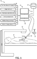
- FIGURE 1 a real-time fusion of anatomical ultrasound information and radiation delivery information system 10 configured for EBRT is schematically illustrated.
- the system is shown using a radiation therapy configuration for EBRT with an EBRT device 12 directed toward a prostate 14 of a subject 16.
- a radiation therapy planning unit 18 images the subject and stores a planning image of the subject as part of the radiation therapy plan 20.
- the planning image can be obtained from a CT image, MR image, and the like.
- the planning image is used to construct the radiation therapy plan 20 which includes the instructions for placement of radiation delivery to anatomic portions of the subject.
- the planning image can include internal or implanted fiducials 22 present in the planning image and aid in registering the planning image to the radiation delivery and real time anatomic information.
- the radiation therapy planning unit 18 maintains the radiation therapy plan 20.
- the radiation therapy plan 20 identifies the planned delivery locations or targets of therapeutic radiation.
- intermediate CT or other planning images can be co-registered with the fiducials 22.
- a segmentation unit 24 segments target tissues such as a tumor.
- the segmentation unit 24 can segment one or more healthy tissues such as OARs in the anatomic imaging region such as the prostate. Other healthy tissues in close proximity to the therapeutic radiation such at the urethra, bladder, etc. can be segmented.
- the system includes an ultrasound imaging unit 26 which images an anatomic portion of the subject in continuous real-time.
- the ultrasound imaging unit can be configured with a 2-dimensional imaging (2D) or a 3-dimensional imaging (3D) imaging probe 28.
- Robotic control and rotation can be used for a 2D imaging probe.
- the ultrasound imaging unit operates in a first coordinate system.
- the first coordinate system can be registered to a room coordinate system through means known in the art, such as video, laser, acoustic, and the like.
- the probe 28 can be marked with markers visible to a plurality of cameras calibrated to the room which provide the position of the probe relative to room coordinates.
- the ultrasound imaging probe 28 includes at least one transducer 30, which emits sound waves at an ultrasonic frequency into the tissues of the subject.
- the sound waves can be emitted according to a sound frequency, direction, duration, timing, and angle.
- the sound waves are reflected and received at the transducer.
- the transducer 30 connects to one or more processors 32 of the ultrasound imaging unit 26 which converts signals transmitted by the transducer to the processor 32 indicative of the received reflected sound waves to images.
- the images are displayed on a display device 34. Segmented tissues can be color coded or otherwise indicated in the displayed ultrasound images based on co-registration with the planning image.
- the probe 28 can be applied externally, such transperineally or trans abdominally as shown, or applied internally such as inserted into a rectum or an esophagus.
- the EBRT delivery device 12 can include a LINear ACcelerator (LINAC), x-ray, particle beam devices, and the like.
- LINAC LINear ACcelerator
- the EBRT delivery device 12 delivers radiation therapy in linear beams projected through the tissues of the subject 16 according to a second coordinate system.
- the beams can be shaped through the use of multi-leaf collimators (MLCs).
- MLCs multi-leaf collimators
- the beams can be gated on and off.
- the beams can be projected from different angles about the subject based on the radiation therapy plan 20.
- the instructions for the EBRT device 12 are executed by the radiation therapy delivery unit 32, which control the precise location, intensity, duration, and shape of the external radiation therapy beam.
- the coordinate system of the EBRT device can be calibrated to the coordinate system of the room.
- the fiducials 22 are internally located and can be implanted.
- the fiducials 22 as shown are implanted in an abdominal region, but can be implanted in any anatomic region.
- the fiducials 22 can be configured with a radiation point source, such as in combined EBRT and brachytherapy, or without the radiation point source as illustrated.
- the implanted fiducials 22 provide for motion tracking and coordinate reference.
- fiducials can be implanted in the prostate and along surfaces of surrounding OARs such as the rectal wall, urethra, bladder, etc. As the subject respires the prostate and/or OARs can move and/or deform.
- the fiducials provide boundary information which reduces or eliminates the margin typically used to accommodate motion.
- the fiducials 22 are encapsulated in a biocompatible capsule to form seeds.
- the fiducials 22 wirelessly transmit a self-identity when activated in response to receiving the ultrasound sound waves.
- each fiducial can be configured with an alphanumeric designator.
- a first fiducial transmits a unique identity of A00001, and a second fiducial transmits a unique identity of A00002, etc.
- the fiducials can be transmit the self-identity based on a predetermined radio frequency.
- the fiducials 22 can be configured with additional circuitry to transmit additional information.
- the transmitted additional information can include a particular ultrasound frequency activation emitted at certain angles or intensity measure by the transducer and received by the fiducial.
- the transmitted additional information can include a checksum or other information which verifies the self-identity or a cycle count which establishes a time currency for the transmission.
- An antenna 36 located external to the subject receives the transmitted information from the fiducials 22.
- the antenna communicates the received signals to an image fusion unit 38 which locates the corresponding fiducial in the first coordinate system of the ultrasound imaging unit 26.
- the image fusion unit fuses the location of the fiducials to the first coordinate system by analyzing the emitted ultrasound signals received by the fiducial as the emitted signals sweep the field of view.
- Time-of-flight measurements provide the axial or radial distance of the fiducial 22 from the emitter 30.
- Amplitude measurements and order in a beam firing sequence provide lateral or angular position of the fiducial. When used with 3-D transducers or 2-D matrix arrays, the elevation of the fiducial is obtained. Based on the timing of the received fiducial self-identity and the firing sequence of the ultrasound probe, the location of the fiducial 22 can be determined relative to the transducer 30 or in the coordinate system of the continuous real-time ultrasound imaging unit 26.
- the image fusion unit 40 fuses the first coordinate system of the continuous real-time imaging unit 26 which contains the anatomic information, e.g. prostate region with the second coordinate system of the therapeutic radiation delivery device 12 which delivers therapeutic radiation, e.g. EBRT device linear beams of therapeutic radiation, based on the fiducials 22.
- the fusion unit can additionally register the planning image of the radiation plan 20 to the fused coordinate system.
- the fiducials provide accurate location within the anatomic region and provide precise motion information not possible with external fiducials. Through the fused coordinate system, the precise location of the anatomic information of the ultrasound images and planning images is known to the radiation therapy delivery device.
- a delivery evaluation unit 42 receives the amount and location of the therapeutic radiation delivered based on the beam shape, duration, and direction from the EBRT device according to the EBRT coordinate system.
- the delivery evaluation unit 42 determines the amount and location of the therapeutic radiation delivered to each of the target and OARs based on the fused coordinate system.
- the delivery evaluation unit 42 tracks the position of the fiducials relative to the radiation beam.
- the tracking can include segmentation information from the planning information and/or entered information concerning tissue boundaries, OARs, targets, etc. relative to the implanted fiducials.
- the radiation planning unit 18 can modify the set of instructions during delivery based on positions of the targets or the OARs relative to the delivered beams of therapeutic radiation according to the fused coordinate system.
- the radiation delivery unit can be controlled to gate the radiation beam when the target tissue moves out of the radiation beam and/or OARs move into the radiation beam.
- the MLC can adaptively move to shape the beam to conform to the movement of the target and/or OARs based on the movement of the fiducials.
- Another example combines the gating on and off with the adaptive MLC movement based on the distance of repetitive motion. The MLC can be used to adapt to repetitive motion within specific parameters which if exceeded gate the beam off.
- the delivery evaluation unit 38 accumulates therapeutic radiation doses received by the OARs and target tissues using the fiducials as reference. For example, the accumulated radiation is accumulated continuously in real-time. Adjustments can be made in the delivery based on the accumulated dose.
- the dose can be accumulated across multiple treatment fractions and/or combined with brachytherapy dose information, e.g. internal therapeutic radiation.
- the accumulated doses can be further used to modify the delivery.
- the MLC can shape the beam further for healthy tissues, based on movement of the tissues into and out of the beam, and receive a threshold amount during the current treatment delivery.
- the processor 32 and the display device 34 can be configured as part of a workstation 44.
- the healthcare practitioner can interact with controls, enter commands, etc. using at least one input device 46 such as a keyboard, mouse, microphone, and the like.
- the processor 20 includes one or more electronic processors or electronic processing device.
- the display 24 displays the continuous real-time ultrasound images, superimposed images or image overlays, menus, panels, and user controls.
- the workstation 44 can be a desktop computer, a laptop, a tablet, a mobile computing device, a smartphone, and the like.
- the various units 18, 24, 26, 38, 40, and 42 are suitably embodied by a programmed or configured electronic data processing device, such as the electronic processor or electronic processing device 32 of the workstation 44, or by a network-based server computer operatively connected with the workstation 44 by a network, or so forth.
- a programmed or configured electronic data processing device such as the electronic processor or electronic processing device 32 of the workstation 44, or by a network-based server computer operatively connected with the workstation 44 by a network, or so forth.
- the disclosed fusion, location, segmentation, evaluation and delivery techniques are suitably implemented using a non-transitory storage medium storing instructions (e.g., software) readable by an electronic data processing device and executable by the electronic data processing device to perform the disclosed techniques.
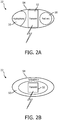
- the fiducial 26 includes a hydrophone or sensor 50 connected to a wireless transmitter 52, and a capsule 54 constructed of biocompatible material which encapsulates the sensor 50, the transmitter 52, and a radiation point source 56 for use in brachytherapy.
- the sensor 50 includes a piezoelectric element activated in response to receiving the emitted ultrasonic sound waves and powers the transmitter 52.
- the piezoelectric element of the sensor can be incorporated into a portion or all of the surface of the capsule.
- the sensor can include lead zirconium titanate (PZT), polyvinylidenefluoride (PVDF), a copolymer, or other piezoelectric material.
- the sensor is about .2 mm in size.
- the capsule 54 is configured cylindrically to be implanted in the subject through a needle inserted into the subject.
- the capsule is sized and shaped to feed through the interior of the needle and drop into a location internal to the body of the subject at the tip of the needle.
- the radiation point source 56 functions as a brachytherapy seed.
- the fiducial 26 illustrated in FIGURE 2B includes the sensor 50, wireless transmitter 52, and the capsule 54.
- the sensor can cover substantially the entire surface of the capsule.
- the circuitry of the transmitter can include limited processing.
- the circuitry can process the received ultrasound sound waves to partially or fully estimate the position in a coordinate system relative to the ultrasound transducer, compress data, and the like.
- the therapeutic radiation delivery mechanism is separated and delivered through a different delivery mechanism.
- an internal fiducial 22 with a 3-dimensional (3D) ultrasound (US) transducer 60 is diagrammatically illustrated in perspective.
- the US transducer emits US sound waves of a predetermined frequency, direction, and time.
- the emitted waves based on direction can be received by the sensor 50 of the fiducial 22.
- a range 62 can be computed.
- An azimuth 64 or lateral angle is computed based on the direction of one or more emitted US sound waves and the amplitude of the received sound wave.
- an elevation 66 is computed based on the direction of one or more emitted US sound waves and the intensity or amplitude of the received US sound wave.
- the individual emitted US sound waves are differentiated by timing in a firing sequence, frequency, or frequency encoding to provide time and/or directional encoding.
- local processing can be performed by the circuitry located in the fiducial 22, and/or in the processor 32 located in the workstation 44 after receipt by the antenna 36 described in reference to FIGURE 1 .
- the fiducials 22 are configured as described in reference to FIGURE 2A which include radiation point sources 56.
- the ultrasound probe 28 is a trans-rectal ultrasound (TRUS) probe applied internally or inserted into a rectum of the subject in close proximity to the prostate for imaging the prostate region.
- TRUS trans-rectal ultrasound
- the radiation plan 20 includes the planned placement of each radiation point source 56 relative to the target tissues.
- the radiation delivery mechanism includes a needle 70 which delivers the fiducials 22 with the radiation point sources 56 into the target locations.
- the needle 70 can be configured with a miniature transducer in the needle tip visible in the continuous real-time ultrasound images.
- the continuous real-time ultrasound imaging unit 26 can project the target locations or planned placement of each point source onto the anatomic image displayed in the displayed ultrasound images.
- the planned placement can guide the healthcare practitioner in the placement of each seed.
- the ultrasound imaging unit 26 overlays the locations of the fiducials in the anatomic images based on the fused coordinate system.
- the locations can be color contrasted, identified with icons such as ellipses, crosses or other shapes, or otherwise identified in the images displayed on the display device 34.
- the delivery evaluation unit 38 identifies the locations and the amounts of delivery therapeutic radiation assigned to each point source.
- the delivery evaluation unit can construct a dose cloud which accumulates the dose of all the point sources in a 3-D format.
- the image fusion unit 40 fuses the locations of the fiducials in the first coordinate system of the ultrasound anatomic images with the second coordinate system of the therapeutic radiation delivery.
- the image fusion unit 32 fuses the second coordinate system of the delivered therapeutic radiation based on the close proximity of the therapeutic radiation point sources to the corresponding fiducial 26.
- the location of the fiducials are tracked by the image fusion unit 40 which tracks the movement of the fiducials through all types of motion including rigid, non-rigid, prostate deformation, and repetitive movement due to respiration and/or cardiac cycles.
- the radiation therapy delivery unit 42 compares the actual placement of the therapeutic radiation with the radiation therapy plan.
- the comparison can include differences in radiation point sources which indicate the variance from a planned position to an actual position.
- the variance can include a change in therapeutic radiation amount or intensity.
- the radiation therapy delivery unit tracks which point sources are delivered and which are outstanding.
- the radiation delivery unit can compare the delivered therapeutic radiation to the planned therapeutic radiation delivery. For example, differences between the 3D actual dose cloud and the 3D planned dose cloud can be superimposed on the continuous real-time ultrasound images. Alternatively, the 3D dose cloud can be computed for effect on each segmented tumor or unhealthy tissue, and/or each segmented healthy tissue such as OARs. Another alternative includes superimposing both the 3D planned dose cloud and the 3D actual dose cloud on the continuous real-time ultrasound images.
- the radiation therapy planning unit 18 can provide "what-if' simulations of changes in positions of planned radiation point sources and delivered radiation point sources.
- a visual display of the resulting dose cloud can superimposed on the segmented unhealthy tissue and/or segmented healthy tissues.
- the resulting dose cloud can be displayed as an overlay on the continuous real-time ultrasound images.
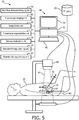
- a fluoroscopic imaging unit 82 includes the processor 32 programmed to generate fluoroscopic images of objects in a field-of-view (FOV) 84 of a fluoroscopic imaging device 86.
- the fluoroscopic imaging device 86 operates on demand or intermittent basis to reduce the imaging radiation exposure to the subject 16.
- the fluoroscopic imaging device is positioned with the FOV to include dropped seeds or radiation point sources 88 in the anatomic region such as the prostate, and fiducials 90 that are separated from the therapeutic radiation and included in the TRUS probe 80.
- the fiducials 90 which include radio-opaque material can be embedded into the shaft, or affixed in a cover of the shaft such as a disposable sleeve configuration.
- the fluoroscopic imaging unit images the dropped seeds and the fiducials in the coordinate system of the fluoroscopic imaging device.
- the dropped seeds and the radio-opaque fiducials have high contrast in the fluoroscopic images.
- the real-time ultrasound imaging unit 26 is registered with the fiducials positioned in the probe and images the anatomic region, which includes the radiation point sources 88.
- the radiation therapy delivery mechanism for the brachytherapy radiation point sources 88 includes the needle 70 inserted into the anatomic portion of the subject and drops seeds containing therapeutic radiation point sources.
- the target locations for the dropped seeds include predetermined locations based on the radiation therapy plan 20.
- the image fusion unit 40 fuses the coordinate system of the fluoroscopic device and the coordinate system of the real-time ultrasound imaging unit and, in some instances, the coordinate system of the planning image.
- the image fusion unit can register the planning image to the ultrasound images.
- the fused coordinate system registers the locations of the radiation point sources 88 to the real-time ultrasound anatomic images.
- the delivery evaluation unit 38 receives actual seed locations according to the coordinate system of the fluoroscopy unit and assigned dose values for each point source of therapeutic radiation.
- the delivery evaluation unit determines the actual anatomic locations of the actual delivered therapeutic radiation based on the fused coordinate system.
- the delivery evaluation unit can determine the amount and location of therapeutic radiation delivered to each of the target and OARs based on the fused coordinate system of the fluoroscopy unit and ultrasound.
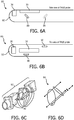
- the TRUS probe 80 is schematically illustrated in a side view and with reference to FIGURE 6B , the TRUS probe 80 is schematically illustrated in a top view.
- the TRUS probe includes a cylindrical shaft with a rounded end configured for insertion into the rectum of the subject.
- the shaft is constructed of a radio-transparent or radio-translucent material and the material is biocompatible.
- the TRUS probe 80 includes in a 3D imaging configuration such as two imaging arrays 30 located on the cylindrical shaft 92 and oriented orthogonally to each other. Other configurations of imaging arrays are contemplated.
- the imaging arrays 30 include transducers which emit the ultrasonic sound waves.
- the fiducials 90 can be embedded in the shaft 92 or included in a thin coat fitted over the TRUS probe 80.
- the fiducials 90 are radio-opaque in contrast to the shaft material.
- the fiducials can include one or more geometric objects positioned in different orientations to provide a three dimensional coordinate reference.
- the fiducials are calibrated to the imaging arrays on the probe of the ultrasound imaging unit.
- FIGURE 6C an intermediate stage of manufacturing the shaft 92 is schematically illustrated in perspective which shows the fiducials 90 embedded in the shaft.
- the shaft is shown in pieces angled oblique to a central axis.
- Fiducial rings are embedded in the shaft as rings on a joining surface between pieces. Lines and/or points are added to an inside or outside surface which run parallel to the central axis. The pieces with the radio-opaque material are joined to form the shaft and then the shaft is rounded.
- the fiducials corresponding to FIGURE 6C are shown as imaged in the fluoroscopic image.
- the fiducials include radio-opaque geometric shapes in different orientations.
- the shapes can include points, lines, ellipses, helicies, rings and/or curved shapes.
- Calibration of the probe 80 can be derived from the manufacturing specifications and/or computer-aid-design (CAD) sketches of the fiducial attachment. Additional fiducial shapes provide most robust calibration.
- CAD computer-aid-design
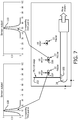
- the diagram illustrates how the 3D position of multiple fiducials 22 can be estimated with a 2D US probe 28.
- the probe includes a transducer 100.
- the imaging plane encounters a first fiducial 104 and a second fiducial 106.
- the fiducial transmits.
- the axial position indicates the z-direction for the first fiducial 104 in a graph 108 at axial position 10 mm and the second fiducial 106 in a second graph 110 at axial position 50 mm.
- the axial position is based on tracked movement of the TRUS probe.
- the 2D position of the fiducial is estimated in the 2D US image and the 3 rd coordinate of the fiducial is provided by the translational position of the TRUS probe.
- the tracked movement of the probe is included in the probe device or ultrasound imaging unit. The probe is moved by axial movement or movement into or out of the rectum.
- the coordinate system of the US imaging unit can operate with a 2D or 3D ultrasound probe and provide the location of the fiducials in a 3D coordinate system.
- fiducials not in the current 2D view can be tracked and the positions noted with different representations on images. For example, fiducials in a higher elevation can be represented differently such as a different color and/or shape from fiducials in the current imaging plane. Fiducials in a lower elevation can be represented as yet another color and/or shape.
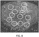
- FIGURE 8 illustrates an exemplary ultrasound image 120 for brachytherapy with therapeutic radiation indicators 122 as ellipses.
- the example is of the portion of the prostate with brachytherapy radiation point sources.
- the delivery evaluation unit 38 identifies the locations of the radiation point sources 56, 88 based on the fused location of the fiducials 22, 90 by the image fusion unit 40.
- the example illustrates the problem of correctly identifying the radiation point sources with artifacts 124 confusingly similar to a radiation point source.
- the locations of the fiducials 22 with corresponding point sources are updated in continuous real-time.
- the representative identification of the point sources can be a system and/or user preference.
- the preference can indicate a shape and/or color.
- Preferences can include a directional indicator such as color coding, dotted lines, shading, or other directional indicator that indicates whether the location is elevated above or below the current imaging plane.
- the locations of the radiation point sources are based on the most recent fluoroscopic image.
- the image can be presented without the identifiers, e.g. ellipses.
- the healthcare practitioner can select a location on the image with the input device 46 to express clinical doubt.
- the system 10 responds with a response indicating the presence or absence of a radiation point source, e.g. "seed present" or "no seed".
- the response can include a distance and/or probability measure.
- the response is based on the location of the point source according to the fused coordinate system updated with the most recent fluoroscopic image.
- the update can include position based on tracking of the point sources among the intermittent fluoroscopic images and measures of periodic motion such as the respiration and/or cardiac cycles. Seed locations can be added to the fiducials of the TRUS probe to improve the registration between images.
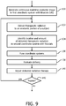
- a step 130 continuous real-time ultrasound images are obtained in a first coordinate system of an anatomic region of a subject with fiducials internal to the subject.
- the images are generated with an US probe which includes at least one transducer which emits ultrasonic sound waves.
- the US probe can be applied to the subject internally or externally.
- the location of the internal fiducials in some implementations, are implanted in and/or around target tissues, and locations determined by a self-identity transmitted in response to received ultrasonic sound waves which activate and power the wireless transmitter.
- the internal fiducials that are implanted can include fiducials implanted in and/or around OARs.
- the implanted fiducials provide motion tracking of the tissues nearby.
- the activation of the implanted fiducial is based on a piezoelectric material of the fiducial, which converts the received ultrasonic sound waves into electrical current.
- the location relative to the probe can be determined based on the firing sequence of the ultrasonic sound waves and/or frequency of the sound waves as described in reference to FIGURES 3 and 7 .
- the internal fiducials are included as part of the internal probe.
- the fiducials affixed to or embedded in the probe are calibrated to the probe and the ultrasound coordinate system.
- the internal fiducials are both implanted and included as part of the internal probe.
- the step can include identifying by segmentation target tissues in the anatomic region, e.g. tumors, diseased tissue, and the like, according to the segmented planning image.
- the step can include tissue deformation and movement analysis using the fiducials as a reference.
- the movement analysis can include repetitive movement such as respiratory and/or cardiac motion, rigid motion such as patient body movement, non-rigid motion such as muscle flexing/relaxing, movement of the probe, movement of a subject support, etc.
- Therapeutic radiation is delivered in amounts and locations according to the radiation therapy plan 20 in a step 132 in a second coordinate system.
- EBRT beams of a shape, duration, intensity, and direction are projected in a coordinate system of the EBRT device and/or brachytherapy point sources of measured amounts of therapeutic radiation are inserted into tissues in a coordinate system of a healthcare practitioner instrument for dropping seeds.
- the fiducials in the second coordinate system are identified.
- the location of the fiducials can be identified either based the fiducials wirelessly transmitting at least a self-identity and/or based on radio-opaque material in an intermittent fluoroscopic image.
- the internal fiducials can be combined with the therapeutic radiation delivery, e.g. incorporated into capsules with the radiation point sources.
- the fiducials can be separated from the therapeutic radiation delivery, e.g. separate implantation and/or included on internal probe.
- the coordinate system of the real-time ultrasound imaging system which includes the anatomic information, is fused with the coordinate system of the therapeutic radiation delivery based on the fiducials in a step 136.
- the fused coordinate system brings the anatomic information of the real-time ultrasound system into a common coordinate system with the therapeutic radiation delivery information.
- the fused coordinate system tracks the location of the fiducials relative to the anatomic information and the delivery of therapeutic radiation.
- a step 138 the locations and amounts of radiation delivered real-time to the anatomic region are evaluated based on the fused coordinate system.
- the evaluation can include segmenting the target tissues, e.g. tumors, and the OARs based on the planning image.
- Therapeutic radiation can be accumulated by voxel location in each segmented structure with the internal fiducials as reference.
- the therapeutic radiation dose can be accumulated for multiple modes of therapeutic radiation delivery, e.g. point sources of brachytherapy, beams of EBRT, and the like.
- the therapeutic radiation dose can be accumulated across treatment fractions.
- the evaluation can include a comparison of actual delivery with the radiation therapy plan 20.
- the delivered radiation therapy can be adjusted in a step 140 during the treatment session.
- the adjustment can include the addition and/or placement of additional radiation point sources.
- the adjustment can include the modification of the external beam of therapeutic radiation in shape, duration, timing, direction, or intensity.
- the beam can be gated on/off or the leaves of the MLC moved timed with the movement of the fiducials and the corresponding target or OARs.
- a decision step continues the method repetitively in real-time during a treatment session or terminates at the end of the session based on the healthcare practitioner command entry with the input device.
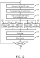
- a step 150 continuous real-time ultrasound images of an anatomic portion of a subject are obtained in a first coordinate system calibrated to fiducials located internally to the subject.
- the TRUS probe includes the calibrated fiducials.
- the continuous real-time ultrasound system can include the 2D or 3D probes described in reference to FIGURES 3 and 7 .
- the step can include segmenting target tissues and/or OARs based on the planning image.
- the target and OAR structures can be identified in the images displayed on the display device.
- the fluoroscopic image is obtained of the anatomic portion of the subject with radiation point sources or seeds and the fiducials in the field of view according to a coordinate system of the fluoroscopic imaging unit.
- the fluoroscopic image can be triggered by command entry from the healthcare practitioner using the input device.
- the imaging unit can alternatively substitute the most recent image or any previous image based on the tracked position of the fiducials corresponding to the position in the previous image.
- the fluoroscopic imaging can be triggered anytime such as after seeds from each needle are implanted, or after seeds from all needles implanted.
- the coordinate system of the real-time ultrasound imaging of the anatomic portion of the subject is fused to the fluoroscopic coordinate system of the therapeutic radiation delivery or radiation point sources based on the fiducials in a step 154.
- the planning image and delivery images can be registered based on organ contours.
- the registration of the continuous real-time ultrasound images to the fluoroscopic images can be improved based on the location of any delivered seeds and/or the location of the needle if equipped with a miniature transducer at the tip which makes the needle visible in the ultrasound.
- the needle and the seeds contrast in the fluoroscopic images.
- steps 156 through 164 the delivery of the therapeutic radiation is evaluated.
- the evaluation can include any one of a seed drop confirmation or seed location confirmation in step 156, dose evaluation in step 158, 3D seed reconstruction in step 160, needle tip location in step 162, or image visualization in step 164.
- step 156 the presence of a seed or seed location is confirmed.
- the process can include automatic identification by segmenting the fluoroscopic image, or based on a request command entry by the healthcare practitioner.
- the request command entry can include selecting with the input device, e.g. mouse, an area on the displayed continuous real-time ultrasound image and receiving a response from the system regarding the presence or absence of the seed.
- the response can include a distance measurement based on the selected point in the image and/or a confidence measure such as a confidence interval, standard deviation, etc.
- the distance measurement can include motion measurement based on the previous imaged repetitive motion of the subject.
- Dose evaluation includes actual delivered radiation based on the seeds present and assigned radiation values. Dose evaluation can include a comparison with the radiation therapy plan 20 such as difference between planned dose and actual dose, differences by segmented tissue, and/or superimposing actual and planned dose amounts.
- the displayed evaluation can be selectable by the healthcare practitioner for a selected location and/or structure, or displayed superimposed on the ultrasound and/or fluoroscopic images.
- 3D seed reconstruction includes locating existing seeds.
- 3D seed reconstruction can include identifying planned seed locations relative to the existing seed locations.
- 3D seed reconstruction can include location of seeds relative to segmented structures. Needle tip location includes locating the needle tip of the radiation point source delivery mechanism or other instrument in the fused coordinate system.
- Image visualization includes combining for display information from the continuous real-time ultrasound with information from the fluoroscopic imaging.
- segment structures can be outlined or colored coded in the image display, seed locations can be indicated with identifiers, dose levels and/or comparisons indicated, etc.
- Image visualization can include orienting the images in the coordinate reference of the fluoroscope, orienting the images in the coordinate reference of the continuous real-time ultrasound images, or another selected perspective such as the position of the needle or healthcare practitioner visual orientation to the subject.
- the radiation therapy plan can be adjusted based on the evaluation steps. For example, the target location for implantation of remaining radiation point sources can be relocated and/or additional target locations identified. The adjustments form a revised radiation therapy plan which can then be re-evaluated in another iteration.
- the radiation therapy treatment delivery continues, in a step 168, with the dropping or placement of additional seeds in target areas according to the radiation therapy plan with any revisions.
- the method continues with a decision step 170 which iterates the steps until the therapeutic radiation delivery is completed or until terminated by the healthcare practitioner. The iterations occur in real-time during delivery of the therapeutic radiation.
Description
- The following relates generally to medical imaging and radiation therapy. It finds particular application in conjunction with real-time imaging of anatomical information using ultrasound and delivery of radiation therapy, and will be described with particular reference thereto. However, it will be understood that it also finds application in other usage scenarios and is not necessarily limited to the aforementioned application.
- Radiation therapy is a procedure which uses radiation to treat a patient, often to kill or destroy harmful tissues, e.g. tumors. Radiation therapy is applied to the tissues of a subject to minimize radiation to healthy tissues. Healthy tissues can include organs at risk (OARs) such as a heart, liver, kidneys, urethra, rectum, bladder, etc. which may be in close proximity to or include unhealthy tissue. Precise placement of radiation during delivery is important to preserve functioning organs while destroying the unhealthy or diseased tissue. Two conventional radiation therapy techniques include brachytherapy and external beam radiation therapy (EBRT). Anatomical images for planning of radiation therapy typically use X-ray computed tomography (CT) which provides detailed anatomical information, but uses x-ray radiation to obtain the anatomical images.
- Brachytherapy typically uses low dose radiation point sources or seeds which are implanted in unhealthy tissues of the subject. The seeds are distributed or dropped through a needle inserted into the unhealthy tissue to provide radiation to surrounding unhealthy tissue. The seeds provide a localized source of radiation. Typically, 50-100 seeds can be implanted into the prostate. Brachytherapy is commonly used for treatment of breast, cervical, prostate, and skin cancers. Precise placement or delivery of the seeds relative to the unhealthy and OARs determines the dose of radiation delivered to the tumor and the OARs. Multiple seeds are distributed in the unhealthy tissue to provide coverage. The coverage is based on the location of each dropped seed and the amount of radiation emitted by each point source.
- EBRT delivers external linear beams of radiation through the body to the target tissues, using a EBRT device such as a linear accelerator (LINAC). Typically, the beams can be shaped and aimed from different directions to help avoid striking OARs. Knowing the precise position of the target and OARs relative to the radiation beam when the external radiation beam is active determines the dose delivery to both the tumor and any healthy tissues in the path of the radiation beam.
- In the delivery of radiation therapy, the precise placement of the radiation relative to the anatomical locations of unhealthy and healthy tissue affects the outcome, particularly the sufficiency of the dose to kill the unhealthy tissue and the side effects of the dose to the healthy tissue. During the delivery of radiation, the location of the healthy and unhealthy tissue is subject to movement of the patient. The movement can include rigid movement, non-rigid movement, deformation of organs, and repetitive movement due to respiration and/or cardiac cycles. One challenge is matching the location of the therapeutic radiation during delivery to the anatomical location of the target and OARs. In other words, one challenge is to register the dosimetric information and anatomical information in a common coordinate system during delivery. A second challenge is measuring the motion accurately in substantially real time such that adjustments can be made during the delivery to correct for position and/or motion.
- For example, in brachytherapy, anatomical information can be obtained from ultrasound, but matching the location of the dropped seeds with the target and OARs can be problematic. Ultrasound (US) can provide continuous real-time anatomical images during delivery of therapeutic radiation without using x-ray radiation. However, visibility of seeds can be obscured or confused with shadowing or other artifacts, which leads to poor sensitivity and specificity. Poor placement of seeds can lead to cold spots or areas where the target is not receiving the proper radiation dose or has spots where OARs receive more than prescribed.
- One approach has been to take intermediate CT images which contrast the seeds with less visibility to organ boundaries in high contrast, but which involves moving the patient from a brachytherapy operative configuration to a CT imaging configuration and returning the patient back to the operative environment to make adjustments for seed placement. The two patient movements are apt to create registration errors between the CT and brachytherapy coordinate systems. The use of CT also adds additional x-ray dose to the patient.
- Another approach is the use of intermittent fluoroscopic images which images the seeds with good contrast and reduces the x-ray imaging dose to the patient compared to CT. However, fluoroscopic images provide less anatomic contrast and are taken intermittently, which makes matching of seed locations to the anatomic locations difficult.
- In EBRT, beams of radiation are directed through the subject. Typically external markers placed on the patient's skin are used to register the patient to the coordinate system of the EBRT delivery device and the coordinate system of high resolution planning images. However, the external marks provide poor internal anatomic information. Due to tissue pliability, registration errors between the external markers and the target and OARs can occur. Without precise anatomic information in a common coordinate system with the external beam coordinate system during delivery of radiation, incomplete dose coverage of the tumor and significant damage to OARs can result. One approach to protecting OARs is to exclude radiation delivery from a margin around OARs large enough to include the entire range of motion. One approach to assuring delivery of the prescribed dose is to irradiate a margin around the target such that the target is in the beam over the range of motion. Due to proximity of the target and OARs, assuring full dose to the target and minimal dose to OARs are often conflicting goals.
- Another approach to identifying the precise location of the organ boundaries and/or motion is the use of electromagnetic (EM) tracking technology. However, EM tracking is sensitive to external distortions such as metallic equipment, prostheses in patients, pacemakers, etc., and depends on positioning of the EM field generator.
- Further, numerous types of implantable fiducials and markers which can be localised and identified are known, see for example
WO 02/39917 EP 1 374 791 - The following discloses a new and improved real-time fusion of anatomical ultrasound information and radiation delivery information for radiation therapies which addresses the above referenced issues, and others.
- In accordance with one aspect of the invention, an implantable fiducial includes a wireless transmitter, a sensor connected to the transmitter, and a capsule constructed of biocompatible material which encapsulates the wireless transmitter and the sensor and configured to be implanted in a subject through a needle inserted into the subject. The wireless transmitter transmits at least a self-identity. The sensor includes a piezoelectric element activated in response to receiving emitted ultrasonic sound waves and powers the transmitter. The implantable fiducial also includes a radiation point source for use in brachytherapy; the radiation point source is encapsulated by the capsule.
- One advantage is the union of continuous real-time anatomic information with the radiation therapy delivery information in a common coordinate system.
- Another advantage resides in ability to adjust delivery of therapeutic radiation during delivery based on positions of the radiation source, the unhealthy tissue and/or the healthy tissue.
- Another advantage resides in use of a non-x-ray imaging source for continuous real-time anatomic imaging information.
- Another advantage resides in precise internal patient motion tracking during radiation delivery.
- Another advantage resides in registering the coordinate system of the radiation source, the coordinate system of a diagnostic image, and a coordinate system of patient anatomy in real time.
- Another advantage resides in providing the clinician the ability to confirm if his/her interpretation of one imaging modality (e.g., US) is correct, by fusing information with another imaging modaility (e.g., fluoroscopy) whenever deemed necessary.
- Still further advantages will be appreciated to those of ordinary skill in the art upon reading and understanding the following detailed description.
- The invention may take form in various components and arrangements of components, and in various steps and arrangement of steps. The drawings are only for purposes of illustration and are not to be construed as limiting the invention.
-
FIGURE 1 schematically illustrates a real-time fusion or registration of anatomical ultrasound information and radiation delivery system configured for EBRT. -
FIGURES 2A-2B schematically illustrate internal fiducials. -
FIGURE 3 diagrammatically illustrates an internal fiducial with a 3-dimensional (3D) ultrasound transducer. -
FIGURE 4 schematically illustrates the real-time fusion of anatomical ultrasound information and radiation delivery system configured for brachytherapy. -
FIGURE 5 schematically illustrates the real-time fusion of anatomical ultrasound information and radiation delivery information system configured for brachytherapy with a trans-rectal ultrasound (TRUS) probe. -
FIGURES 6A-6D schematically illustrates the trans-rectal ultrasound (TRUS) probe with radio-opaque fiducials. -
FIGURE 7 diagrammatically illustrates the internal fiducial with a 2-dimensional (2D) ultrasound transducer. -
FIGURE 8 illustrates an exemplary ultrasound image for brachytherapy with therapeutic radiation indicator. -
FIGURE 9 flowcharts one method of real-time fusion of anatomical ultrasound information and radiation delivery information for interventional radiation therapy. -
FIGURE 10 flowcharts one method of using the real-time fusion of anatomical ultrasound information and radiation delivery information for brachytherapy with a TRUS probe. - With reference to
FIGURE 1 , a real-time fusion of anatomical ultrasound information and radiationdelivery information system 10 configured for EBRT is schematically illustrated. The system is shown using a radiation therapy configuration for EBRT with anEBRT device 12 directed toward aprostate 14 of a subject 16. A radiationtherapy planning unit 18 images the subject and stores a planning image of the subject as part of theradiation therapy plan 20. The planning image can be obtained from a CT image, MR image, and the like. The planning image is used to construct theradiation therapy plan 20 which includes the instructions for placement of radiation delivery to anatomic portions of the subject. The planning image can include internal or implantedfiducials 22 present in the planning image and aid in registering the planning image to the radiation delivery and real time anatomic information. - The radiation
therapy planning unit 18 maintains theradiation therapy plan 20. Theradiation therapy plan 20 identifies the planned delivery locations or targets of therapeutic radiation. For fractionated treatments, intermediate CT or other planning images can be co-registered with thefiducials 22. - A
segmentation unit 24 segments target tissues such as a tumor. Thesegmentation unit 24 can segment one or more healthy tissues such as OARs in the anatomic imaging region such as the prostate. Other healthy tissues in close proximity to the therapeutic radiation such at the urethra, bladder, etc. can be segmented. - The system includes an
ultrasound imaging unit 26 which images an anatomic portion of the subject in continuous real-time. The ultrasound imaging unit can be configured with a 2-dimensional imaging (2D) or a 3-dimensional imaging (3D)imaging probe 28. Robotic control and rotation can be used for a 2D imaging probe. The ultrasound imaging unit operates in a first coordinate system. The first coordinate system can be registered to a room coordinate system through means known in the art, such as video, laser, acoustic, and the like. For example, theprobe 28 can be marked with markers visible to a plurality of cameras calibrated to the room which provide the position of the probe relative to room coordinates. - The
ultrasound imaging probe 28 includes at least onetransducer 30, which emits sound waves at an ultrasonic frequency into the tissues of the subject. The sound waves can be emitted according to a sound frequency, direction, duration, timing, and angle. The sound waves are reflected and received at the transducer. Thetransducer 30 connects to one ormore processors 32 of theultrasound imaging unit 26 which converts signals transmitted by the transducer to theprocessor 32 indicative of the received reflected sound waves to images. The images are displayed on adisplay device 34. Segmented tissues can be color coded or otherwise indicated in the displayed ultrasound images based on co-registration with the planning image. Theprobe 28 can be applied externally, such transperineally or trans abdominally as shown, or applied internally such as inserted into a rectum or an esophagus. - The
EBRT delivery device 12 can include a LINear ACcelerator (LINAC), x-ray, particle beam devices, and the like. TheEBRT delivery device 12 delivers radiation therapy in linear beams projected through the tissues of the subject 16 according to a second coordinate system. The beams can be shaped through the use of multi-leaf collimators (MLCs). The beams can be gated on and off. The beams can be projected from different angles about the subject based on theradiation therapy plan 20. The instructions for theEBRT device 12 are executed by the radiationtherapy delivery unit 32, which control the precise location, intensity, duration, and shape of the external radiation therapy beam. The coordinate system of the EBRT device can be calibrated to the coordinate system of the room. - The fiducials 22 are internally located and can be implanted. The fiducials 22 as shown are implanted in an abdominal region, but can be implanted in any anatomic region. The fiducials 22 can be configured with a radiation point source, such as in combined EBRT and brachytherapy, or without the radiation point source as illustrated. The implanted fiducials 22 provide for motion tracking and coordinate reference. For example, fiducials can be implanted in the prostate and along surfaces of surrounding OARs such as the rectal wall, urethra, bladder, etc. As the subject respires the prostate and/or OARs can move and/or deform. The fiducials provide boundary information which reduces or eliminates the margin typically used to accommodate motion.
- The fiducials 22 are encapsulated in a biocompatible capsule to form seeds. The fiducials 22 wirelessly transmit a self-identity when activated in response to receiving the ultrasound sound waves. For example, each fiducial can be configured with an alphanumeric designator. A first fiducial transmits a unique identity of A00001, and a second fiducial transmits a unique identity of A00002, etc. Alternatively, the fiducials can be transmit the self-identity based on a predetermined radio frequency. The fiducials 22 can be configured with additional circuitry to transmit additional information. For example, the transmitted additional information can include a particular ultrasound frequency activation emitted at certain angles or intensity measure by the transducer and received by the fiducial. In another example, the transmitted additional information can include a checksum or other information which verifies the self-identity or a cycle count which establishes a time currency for the transmission.
- An
antenna 36 located external to the subject receives the transmitted information from thefiducials 22. The antenna communicates the received signals to animage fusion unit 38 which locates the corresponding fiducial in the first coordinate system of theultrasound imaging unit 26. The image fusion unit fuses the location of the fiducials to the first coordinate system by analyzing the emitted ultrasound signals received by the fiducial as the emitted signals sweep the field of view. Time-of-flight measurements provide the axial or radial distance of the fiducial 22 from theemitter 30. Amplitude measurements and order in a beam firing sequence provide lateral or angular position of the fiducial. When used with 3-D transducers or 2-D matrix arrays, the elevation of the fiducial is obtained. Based on the timing of the received fiducial self-identity and the firing sequence of the ultrasound probe, the location of the fiducial 22 can be determined relative to thetransducer 30 or in the coordinate system of the continuous real-timeultrasound imaging unit 26. - The
image fusion unit 40 fuses the first coordinate system of the continuous real-time imaging unit 26 which contains the anatomic information, e.g. prostate region with the second coordinate system of the therapeuticradiation delivery device 12 which delivers therapeutic radiation, e.g. EBRT device linear beams of therapeutic radiation, based on thefiducials 22. The fusion unit can additionally register the planning image of theradiation plan 20 to the fused coordinate system. The fiducials provide accurate location within the anatomic region and provide precise motion information not possible with external fiducials. Through the fused coordinate system, the precise location of the anatomic information of the ultrasound images and planning images is known to the radiation therapy delivery device. - A
delivery evaluation unit 42 receives the amount and location of the therapeutic radiation delivered based on the beam shape, duration, and direction from the EBRT device according to the EBRT coordinate system. Thedelivery evaluation unit 42 determines the amount and location of the therapeutic radiation delivered to each of the target and OARs based on the fused coordinate system. Thedelivery evaluation unit 42 tracks the position of the fiducials relative to the radiation beam. The tracking can include segmentation information from the planning information and/or entered information concerning tissue boundaries, OARs, targets, etc. relative to the implanted fiducials. - The
radiation planning unit 18 can modify the set of instructions during delivery based on positions of the targets or the OARs relative to the delivered beams of therapeutic radiation according to the fused coordinate system. For example, the radiation delivery unit can be controlled to gate the radiation beam when the target tissue moves out of the radiation beam and/or OARs move into the radiation beam. In another example, the MLC can adaptively move to shape the beam to conform to the movement of the target and/or OARs based on the movement of the fiducials. Another example combines the gating on and off with the adaptive MLC movement based on the distance of repetitive motion. The MLC can be used to adapt to repetitive motion within specific parameters which if exceeded gate the beam off. - The
delivery evaluation unit 38 accumulates therapeutic radiation doses received by the OARs and target tissues using the fiducials as reference. For example, the accumulated radiation is accumulated continuously in real-time. Adjustments can be made in the delivery based on the accumulated dose. The dose can be accumulated across multiple treatment fractions and/or combined with brachytherapy dose information, e.g. internal therapeutic radiation. The accumulated doses can be further used to modify the delivery. For example, the MLC can shape the beam further for healthy tissues, based on movement of the tissues into and out of the beam, and receive a threshold amount during the current treatment delivery. - The
processor 32 and thedisplay device 34 can be configured as part of aworkstation 44. The healthcare practitioner can interact with controls, enter commands, etc. using at least oneinput device 46 such as a keyboard, mouse, microphone, and the like. Theprocessor 20 includes one or more electronic processors or electronic processing device. Thedisplay 24 displays the continuous real-time ultrasound images, superimposed images or image overlays, menus, panels, and user controls. Theworkstation 44 can be a desktop computer, a laptop, a tablet, a mobile computing device, a smartphone, and the like. - The
various units electronic processing device 32 of theworkstation 44, or by a network-based server computer operatively connected with theworkstation 44 by a network, or so forth. The disclosed fusion, location, segmentation, evaluation and delivery techniques are suitably implemented using a non-transitory storage medium storing instructions (e.g., software) readable by an electronic data processing device and executable by the electronic data processing device to perform the disclosed techniques. - With reference to
FIGURES 2A and 2B internal fiducials 22 are schematically illustrated. InFIGURE 2A , the fiducial 26 includes a hydrophone orsensor 50 connected to awireless transmitter 52, and acapsule 54 constructed of biocompatible material which encapsulates thesensor 50, thetransmitter 52, and aradiation point source 56 for use in brachytherapy. Thesensor 50 includes a piezoelectric element activated in response to receiving the emitted ultrasonic sound waves and powers thetransmitter 52. The piezoelectric element of the sensor can be incorporated into a portion or all of the surface of the capsule. The sensor can include lead zirconium titanate (PZT), polyvinylidenefluoride (PVDF), a copolymer, or other piezoelectric material. The sensor is about .2 mm in size. Thecapsule 54 is configured cylindrically to be implanted in the subject through a needle inserted into the subject. The capsule is sized and shaped to feed through the interior of the needle and drop into a location internal to the body of the subject at the tip of the needle. Theradiation point source 56 functions as a brachytherapy seed. - The fiducial 26 illustrated in
FIGURE 2B includes thesensor 50,wireless transmitter 52, and thecapsule 54. In the configuration ofFIGURE 2B , the sensor can cover substantially the entire surface of the capsule. The circuitry of the transmitter can include limited processing. For example, in addition to transmitting the self-identity or other information, the circuitry can process the received ultrasound sound waves to partially or fully estimate the position in a coordinate system relative to the ultrasound transducer, compress data, and the like. The therapeutic radiation delivery mechanism is separated and delivered through a different delivery mechanism. - With reference to
FIGURE 3 an internal fiducial 22 with a 3-dimensional (3D) ultrasound (US)transducer 60 is diagrammatically illustrated in perspective. The US transducer emits US sound waves of a predetermined frequency, direction, and time. The emitted waves based on direction can be received by thesensor 50 of the fiducial 22. Based on the time between emission and receipt, arange 62 can be computed. Anazimuth 64 or lateral angle is computed based on the direction of one or more emitted US sound waves and the amplitude of the received sound wave. In the 3-D US, anelevation 66 is computed based on the direction of one or more emitted US sound waves and the intensity or amplitude of the received US sound wave. The individual emitted US sound waves are differentiated by timing in a firing sequence, frequency, or frequency encoding to provide time and/or directional encoding. As described in reference toFIGURES 2A and 2B , local processing can be performed by the circuitry located in the fiducial 22, and/or in theprocessor 32 located in theworkstation 44 after receipt by theantenna 36 described in reference toFIGURE 1 . - With reference to
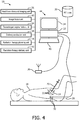
FIGURE 4 , the real-time fusion of anatomical ultrasound information andradiation delivery system 10 configured for brachytherapy is schematically illustrated. The fiducials 22 are configured as described in reference toFIGURE 2A which includeradiation point sources 56. Theultrasound probe 28 is a trans-rectal ultrasound (TRUS) probe applied internally or inserted into a rectum of the subject in close proximity to the prostate for imaging the prostate region. Theradiation plan 20 includes the planned placement of eachradiation point source 56 relative to the target tissues. The radiation delivery mechanism includes aneedle 70 which delivers the fiducials 22 with theradiation point sources 56 into the target locations. Theneedle 70 can be configured with a miniature transducer in the needle tip visible in the continuous real-time ultrasound images. - The continuous real-time
ultrasound imaging unit 26 can project the target locations or planned placement of each point source onto the anatomic image displayed in the displayed ultrasound images. The planned placement can guide the healthcare practitioner in the placement of each seed. Theultrasound imaging unit 26 overlays the locations of the fiducials in the anatomic images based on the fused coordinate system. The locations can be color contrasted, identified with icons such as ellipses, crosses or other shapes, or otherwise identified in the images displayed on thedisplay device 34. - The
delivery evaluation unit 38 identifies the locations and the amounts of delivery therapeutic radiation assigned to each point source. The delivery evaluation unit can construct a dose cloud which accumulates the dose of all the point sources in a 3-D format. - The
image fusion unit 40 fuses the locations of the fiducials in the first coordinate system of the ultrasound anatomic images with the second coordinate system of the therapeutic radiation delivery. Theimage fusion unit 32 fuses the second coordinate system of the delivered therapeutic radiation based on the close proximity of the therapeutic radiation point sources to the corresponding fiducial 26. The location of the fiducials are tracked by theimage fusion unit 40 which tracks the movement of the fiducials through all types of motion including rigid, non-rigid, prostate deformation, and repetitive movement due to respiration and/or cardiac cycles. - The radiation
therapy delivery unit 42 compares the actual placement of the therapeutic radiation with the radiation therapy plan. The comparison can include differences in radiation point sources which indicate the variance from a planned position to an actual position. The variance can include a change in therapeutic radiation amount or intensity. The radiation therapy delivery unit tracks which point sources are delivered and which are outstanding. The radiation delivery unit can compare the delivered therapeutic radiation to the planned therapeutic radiation delivery. For example, differences between the 3D actual dose cloud and the 3D planned dose cloud can be superimposed on the continuous real-time ultrasound images. Alternatively, the 3D dose cloud can be computed for effect on each segmented tumor or unhealthy tissue, and/or each segmented healthy tissue such as OARs. Another alternative includes superimposing both the 3D planned dose cloud and the 3D actual dose cloud on the continuous real-time ultrasound images. - The radiation
therapy planning unit 18 can provide "what-if' simulations of changes in positions of planned radiation point sources and delivered radiation point sources. A visual display of the resulting dose cloud can superimposed on the segmented unhealthy tissue and/or segmented healthy tissues. During implantation of the seeds, the resulting dose cloud can be displayed as an overlay on the continuous real-time ultrasound images. - With reference to
FIGURE 5 , an the real-time fusion of anatomical ultrasound information and radiationdelivery information system 10 configured for brachytherapy with aTRUS probe 80 is schematically illustrated. Afluoroscopic imaging unit 82 includes theprocessor 32 programmed to generate fluoroscopic images of objects in a field-of-view (FOV) 84 of afluoroscopic imaging device 86. Thefluoroscopic imaging device 86 operates on demand or intermittent basis to reduce the imaging radiation exposure to the subject 16. The fluoroscopic imaging device is positioned with the FOV to include dropped seeds orradiation point sources 88 in the anatomic region such as the prostate, and fiducials 90 that are separated from the therapeutic radiation and included in theTRUS probe 80. - The
fiducials 90, which include radio-opaque material can be embedded into the shaft, or affixed in a cover of the shaft such as a disposable sleeve configuration. The fluoroscopic imaging unit images the dropped seeds and the fiducials in the coordinate system of the fluoroscopic imaging device. The dropped seeds and the radio-opaque fiducials have high contrast in the fluoroscopic images. The real-timeultrasound imaging unit 26 is registered with the fiducials positioned in the probe and images the anatomic region, which includes theradiation point sources 88. - The radiation therapy delivery mechanism for the brachytherapy
radiation point sources 88 includes theneedle 70 inserted into the anatomic portion of the subject and drops seeds containing therapeutic radiation point sources. The target locations for the dropped seeds include predetermined locations based on theradiation therapy plan 20. - The
image fusion unit 40 fuses the coordinate system of the fluoroscopic device and the coordinate system of the real-time ultrasound imaging unit and, in some instances, the coordinate system of the planning image. The image fusion unit can register the planning image to the ultrasound images. The fused coordinate system registers the locations of theradiation point sources 88 to the real-time ultrasound anatomic images. - The
delivery evaluation unit 38 receives actual seed locations according to the coordinate system of the fluoroscopy unit and assigned dose values for each point source of therapeutic radiation. The delivery evaluation unit determines the actual anatomic locations of the actual delivered therapeutic radiation based on the fused coordinate system. The delivery evaluation unit can determine the amount and location of therapeutic radiation delivered to each of the target and OARs based on the fused coordinate system of the fluoroscopy unit and ultrasound. - With reference to
FIGURE 6A , theTRUS probe 80 is schematically illustrated in a side view and with reference toFIGURE 6B , theTRUS probe 80 is schematically illustrated in a top view. The TRUS probe includes a cylindrical shaft with a rounded end configured for insertion into the rectum of the subject. The shaft is constructed of a radio-transparent or radio-translucent material and the material is biocompatible. - The
TRUS probe 80 includes in a 3D imaging configuration such as twoimaging arrays 30 located on thecylindrical shaft 92 and oriented orthogonally to each other. Other configurations of imaging arrays are contemplated. Theimaging arrays 30 include transducers which emit the ultrasonic sound waves. - The fiducials 90 can be embedded in the
shaft 92 or included in a thin coat fitted over theTRUS probe 80. The fiducials 90 are radio-opaque in contrast to the shaft material. The fiducials can include one or more geometric objects positioned in different orientations to provide a three dimensional coordinate reference. The fiducials are calibrated to the imaging arrays on the probe of the ultrasound imaging unit. - With reference to
FIGURE 6C , an intermediate stage of manufacturing theshaft 92 is schematically illustrated in perspective which shows thefiducials 90 embedded in the shaft. The shaft is shown in pieces angled oblique to a central axis. Fiducial rings are embedded in the shaft as rings on a joining surface between pieces. Lines and/or points are added to an inside or outside surface which run parallel to the central axis. The pieces with the radio-opaque material are joined to form the shaft and then the shaft is rounded. - With reference to
FIGURE 6D , the fiducials corresponding toFIGURE 6C are shown as imaged in the fluoroscopic image. The fiducials include radio-opaque geometric shapes in different orientations. The shapes can include points, lines, ellipses, helicies, rings and/or curved shapes. Calibration of theprobe 80 can be derived from the manufacturing specifications and/or computer-aid-design (CAD) sketches of the fiducial attachment. Additional fiducial shapes provide most robust calibration. - With reference to
FIGURE 7 the internal fiducial 22 with a 2-dimensional (2D)ultrasound transducer 100 in aprobe 28 and tracked movement of the transducer to provide three dimensional coordinates. The diagram illustrates how the 3D position ofmultiple fiducials 22 can be estimated with a2D US probe 28. The probe includes atransducer 100. For example, as a 2DUS imaging plane 102 moves in the z direction, the imaging plane encounters a first fiducial 104 and a second fiducial 106. As the ultrasonic waves in the plane encounter the fiducial, the fiducial transmits. The axial position indicates the z-direction for the first fiducial 104 in agraph 108 ataxial position 10 mm and the second fiducial 106 in asecond graph 110 ataxial position 50 mm. The axial position is based on tracked movement of the TRUS probe. The 2D position of the fiducial is estimated in the 2D US image and the 3rd coordinate of the fiducial is provided by the translational position of the TRUS probe. The tracked movement of the probe is included in the probe device or ultrasound imaging unit. The probe is moved by axial movement or movement into or out of the rectum. Thus, the coordinate system of the US imaging unit can operate with a 2D or 3D ultrasound probe and provide the location of the fiducials in a 3D coordinate system. Locations of fiducials not in the current 2D view can be tracked and the positions noted with different representations on images. For example, fiducials in a higher elevation can be represented differently such as a different color and/or shape from fiducials in the current imaging plane. Fiducials in a lower elevation can be represented as yet another color and/or shape. -
FIGURE 8 illustrates an exemplary ultrasound image 120 for brachytherapy withtherapeutic radiation indicators 122 as ellipses. The example is of the portion of the prostate with brachytherapy radiation point sources. Thedelivery evaluation unit 38 identifies the locations of theradiation point sources fiducials image fusion unit 40. The example illustrates the problem of correctly identifying the radiation point sources withartifacts 124 confusingly similar to a radiation point source. - The locations of the
fiducials 22 with corresponding point sources are updated in continuous real-time. The representative identification of the point sources can be a system and/or user preference. The preference can indicate a shape and/or color. Preferences can include a directional indicator such as color coding, dotted lines, shading, or other directional indicator that indicates whether the location is elevated above or below the current imaging plane. - In
system 10 described in reference toFIGURE 5 , the locations of the radiation point sources are based on the most recent fluoroscopic image. The image can be presented without the identifiers, e.g. ellipses. In another implementation, the healthcare practitioner can select a location on the image with theinput device 46 to express clinical doubt. Thesystem 10 responds with a response indicating the presence or absence of a radiation point source, e.g. "seed present" or "no seed". Alternatively, the response can include a distance and/or probability measure. The response is based on the location of the point source according to the fused coordinate system updated with the most recent fluoroscopic image. The update can include position based on tracking of the point sources among the intermittent fluoroscopic images and measures of periodic motion such as the respiration and/or cardiac cycles. Seed locations can be added to the fiducials of the TRUS probe to improve the registration between images. - With reference to
FIGURE 9 , one method of real-time fusion of anatomical ultrasound information and radiation delivery information for interventional radiation therapy is flowcharted. In astep 130, continuous real-time ultrasound images are obtained in a first coordinate system of an anatomic region of a subject with fiducials internal to the subject. The images are generated with an US probe which includes at least one transducer which emits ultrasonic sound waves. The US probe can be applied to the subject internally or externally. The location of the internal fiducials, in some implementations, are implanted in and/or around target tissues, and locations determined by a self-identity transmitted in response to received ultrasonic sound waves which activate and power the wireless transmitter. The internal fiducials that are implanted, can include fiducials implanted in and/or around OARs. The implanted fiducials provide motion tracking of the tissues nearby. The activation of the implanted fiducial is based on a piezoelectric material of the fiducial, which converts the received ultrasonic sound waves into electrical current. The location relative to the probe can be determined based on the firing sequence of the ultrasonic sound waves and/or frequency of the sound waves as described in reference toFIGURES 3 and7 . In other implementations, the internal fiducials are included as part of the internal probe. The fiducials affixed to or embedded in the probe are calibrated to the probe and the ultrasound coordinate system. In some implementations, the internal fiducials are both implanted and included as part of the internal probe. - The step can include identifying by segmentation target tissues in the anatomic region, e.g. tumors, diseased tissue, and the like, according to the segmented planning image. The step can include tissue deformation and movement analysis using the fiducials as a reference. The movement analysis can include repetitive movement such as respiratory and/or cardiac motion, rigid motion such as patient body movement, non-rigid motion such as muscle flexing/relaxing, movement of the probe, movement of a subject support, etc.
- Therapeutic radiation is delivered in amounts and locations according to the
radiation therapy plan 20 in astep 132 in a second coordinate system. For example, EBRT beams of a shape, duration, intensity, and direction are projected in a coordinate system of the EBRT device and/or brachytherapy point sources of measured amounts of therapeutic radiation are inserted into tissues in a coordinate system of a healthcare practitioner instrument for dropping seeds. In astep 134, the fiducials in the second coordinate system are identified. The location of the fiducials can be identified either based the fiducials wirelessly transmitting at least a self-identity and/or based on radio-opaque material in an intermittent fluoroscopic image. The internal fiducials can be combined with the therapeutic radiation delivery, e.g. incorporated into capsules with the radiation point sources. The fiducials can be separated from the therapeutic radiation delivery, e.g. separate implantation and/or included on internal probe. - The coordinate system of the real-time ultrasound imaging system, which includes the anatomic information, is fused with the coordinate system of the therapeutic radiation delivery based on the fiducials in a
step 136. The fused coordinate system brings the anatomic information of the real-time ultrasound system into a common coordinate system with the therapeutic radiation delivery information. The fused coordinate system tracks the location of the fiducials relative to the anatomic information and the delivery of therapeutic radiation. - In a
step 138, the locations and amounts of radiation delivered real-time to the anatomic region are evaluated based on the fused coordinate system. The evaluation can include segmenting the target tissues, e.g. tumors, and the OARs based on the planning image. Therapeutic radiation can be accumulated by voxel location in each segmented structure with the internal fiducials as reference. The therapeutic radiation dose can be accumulated for multiple modes of therapeutic radiation delivery, e.g. point sources of brachytherapy, beams of EBRT, and the like. The therapeutic radiation dose can be accumulated across treatment fractions. The evaluation can include a comparison of actual delivery with theradiation therapy plan 20. - The delivered radiation therapy can be adjusted in a
step 140 during the treatment session. The adjustment can include the addition and/or placement of additional radiation point sources. The adjustment can include the modification of the external beam of therapeutic radiation in shape, duration, timing, direction, or intensity. For example, the beam can be gated on/off or the leaves of the MLC moved timed with the movement of the fiducials and the corresponding target or OARs. - In a
step 142, a decision step continues the method repetitively in real-time during a treatment session or terminates at the end of the session based on the healthcare practitioner command entry with the input device. - With reference to
FIGURE 10 , one method of using the real-time fusion of anatomical ultrasound information and radiationdelivery information system 10 for brachytherapy with the TRUS probe is flowcharted. In astep 150, continuous real-time ultrasound images of an anatomic portion of a subject are obtained in a first coordinate system calibrated to fiducials located internally to the subject. The TRUS probe includes the calibrated fiducials. The continuous real-time ultrasound system can include the 2D or 3D probes described in reference toFIGURES 3 and7 . The step can include segmenting target tissues and/or OARs based on the planning image. The target and OAR structures can be identified in the images displayed on the display device. - In a
step 142, the fluoroscopic image is obtained of the anatomic portion of the subject with radiation point sources or seeds and the fiducials in the field of view according to a coordinate system of the fluoroscopic imaging unit. The fluoroscopic image can be triggered by command entry from the healthcare practitioner using the input device. The imaging unit can alternatively substitute the most recent image or any previous image based on the tracked position of the fiducials corresponding to the position in the previous image. The fluoroscopic imaging can be triggered anytime such as after seeds from each needle are implanted, or after seeds from all needles implanted. - The coordinate system of the real-time ultrasound imaging of the anatomic portion of the subject is fused to the fluoroscopic coordinate system of the therapeutic radiation delivery or radiation point sources based on the fiducials in a
step 154. For example, the planning image and delivery images can be registered based on organ contours. The registration of the continuous real-time ultrasound images to the fluoroscopic images can be improved based on the location of any delivered seeds and/or the location of the needle if equipped with a miniature transducer at the tip which makes the needle visible in the ultrasound. The needle and the seeds contrast in the fluoroscopic images. - In
steps 156 through 164 the delivery of the therapeutic radiation is evaluated. The evaluation can include any one of a seed drop confirmation or seed location confirmation instep 156, dose evaluation instep step 160, needle tip location instep 162, or image visualization instep 164. Instep 156, the presence of a seed or seed location is confirmed. The process can include automatic identification by segmenting the fluoroscopic image, or based on a request command entry by the healthcare practitioner. The request command entry can include selecting with the input device, e.g. mouse, an area on the displayed continuous real-time ultrasound image and receiving a response from the system regarding the presence or absence of the seed. The response can include a distance measurement based on the selected point in the image and/or a confidence measure such as a confidence interval, standard deviation, etc. The distance measurement can include motion measurement based on the previous imaged repetitive motion of the subject. - Dose evaluation includes actual delivered radiation based on the seeds present and assigned radiation values. Dose evaluation can include a comparison with the
radiation therapy plan 20 such as difference between planned dose and actual dose, differences by segmented tissue, and/or superimposing actual and planned dose amounts. The displayed evaluation can be selectable by the healthcare practitioner for a selected location and/or structure, or displayed superimposed on the ultrasound and/or fluoroscopic images. - 3D seed reconstruction includes locating existing seeds. 3D seed reconstruction can include identifying planned seed locations relative to the existing seed locations. 3D seed reconstruction can include location of seeds relative to segmented structures. Needle tip location includes locating the needle tip of the radiation point source delivery mechanism or other instrument in the fused coordinate system.
- Image visualization includes combining for display information from the continuous real-time ultrasound with information from the fluoroscopic imaging. For example, segment structures can be outlined or colored coded in the image display, seed locations can be indicated with identifiers, dose levels and/or comparisons indicated, etc. Image visualization can include orienting the images in the coordinate reference of the fluoroscope, orienting the images in the coordinate reference of the continuous real-time ultrasound images, or another selected perspective such as the position of the needle or healthcare practitioner visual orientation to the subject.
- In a
step 166, the radiation therapy plan can be adjusted based on the evaluation steps. For example, the target location for implantation of remaining radiation point sources can be relocated and/or additional target locations identified. The adjustments form a revised radiation therapy plan which can then be re-evaluated in another iteration. - The radiation therapy treatment delivery continues, in a
step 168, with the dropping or placement of additional seeds in target areas according to the radiation therapy plan with any revisions. The method continues with adecision step 170 which iterates the steps until the therapeutic radiation delivery is completed or until terminated by the healthcare practitioner. The iterations occur in real-time during delivery of the therapeutic radiation. - It is to be appreciated that in connection with the particular illustrative implementations presented herein certain structural and/or function features are described as being incorporated in defined elements and/or components. However, it is contemplated that these features may, to the same or similar benefit, also likewise be incorporated in other elements and/or components where appropriate. It is also to be appreciated that different implementations may be selectively employed as appropriate to achieve other alternate implementations suited for desired applications, the other alternate implementations thereby realizing the respective advantages of the implementations incorporated therein.
- It is also to be appreciated that particular elements or components described herein may have their functionality suitably implemented via hardware, software, firmware or a combination thereof. Additionally, it is to be appreciated that certain elements described herein as incorporated together may under suitable circumstances be stand-alone elements or otherwise divided. Similarly, a plurality of particular functions described as being carried out by one particular element may be carried out by a plurality of distinct elements acting independently to carry out individual functions, or certain individual functions may be split-up and carried out by a plurality of distinct elements acting in concert. Alternately, some elements or components otherwise described and/or shown herein as distinct from one another may be physically or functionally combined where appropriate.
- The invention is defined in the claims, other embodiments being merely exemplary.
Claims (5)
- An implantable fiducial (22), adapted to be used together with an ultrasound imaging unit (26), the ultrasound imaging unit being adapted to emit ultrasonic sound waves;
the implantable fiducial (22) comprising: comprising:a wireless transmitter (52);a sensor (50); anda capsule (54);wherein the wireless transmitter (52) is configured to transmit at least a self-identity;wherein the sensor (50) is connected to the transmitter and includes a piezoelectric element which is configured to power the transmitter; andwherein the capsule (54) is constructed of biocompatible material which encapsulates the wireless transmitter and the sensor and is configured to be implanted in a subject through a needle when inserted into a subject;characterised in thatthe piezoelectric element is activatable in response to received ultrasonic sound waves emitted by the ultrasound imaging unit (26); and wherein the implantable fiducial (22) further comprises a radiation point source (56) adapted to be used in brachytherapy, and wherein the radiation point source (56) is encapsulated by the capsule (54). - The implantable fiducial (22) according to claim 1 wherein the wireless transmitter (52) is further configured to transmit at least one of the following information: i) a frequency of ultrasound activation emitted at a predetermined angle as detected by the sensor (50) ii) an intensity of ultrasound activation as detected by the sensor (50) iii) a checksum for verifying the self-identity iv) an ultrasound cycle count for establishing a time currency for the transmission.
- The implantable fiducial (22) according to any previous claim wherein the piezoelectric element comprises lead zirconium titanate, PZT, or polyvinylidenefluoride, PVDF, or a copolymer.
- The implantable fiducial (22) according to any previous claim wherein the capsule (54) is configured cylindrically for implantation in a subject through a needle.
- The implantable fiducial (22) according to claim 1 further comprising radio-opaque material for visualization in a fluoroscopic image.
Priority Applications (1)
| Application Number | Priority Date | Filing Date | Title |
|---|---|---|---|
| EP18182420.2A EP3421091A1 (en) | 2013-12-12 | 2014-12-05 | Real-time fusion of anatomical ultrasound information and radiation delivery information for radiation therapies |
Applications Claiming Priority (3)
| Application Number | Priority Date | Filing Date | Title |
|---|---|---|---|
| US201361915081P | 2013-12-12 | 2013-12-12 | |
| EP14824112.8A EP3079767B1 (en) | 2013-12-12 | 2014-12-05 | Real-time fusion of anatomical ultrasound information and radiation delivery information for radiation therapies |
| PCT/IB2014/066616 WO2015087217A1 (en) | 2013-12-12 | 2014-12-05 | Real-time fusion of anatomical ultrasound information and radiation delivery information for radiation therapies |
Related Parent Applications (2)
| Application Number | Title | Priority Date | Filing Date |
|---|---|---|---|
| EP14824112.8A Division-Into EP3079767B1 (en) | 2013-12-12 | 2014-12-05 | Real-time fusion of anatomical ultrasound information and radiation delivery information for radiation therapies |
| EP14824112.8A Division EP3079767B1 (en) | 2013-12-12 | 2014-12-05 | Real-time fusion of anatomical ultrasound information and radiation delivery information for radiation therapies |
Related Child Applications (2)
| Application Number | Title | Priority Date | Filing Date |
|---|---|---|---|
| EP18182420.2A Division-Into EP3421091A1 (en) | 2013-12-12 | 2014-12-05 | Real-time fusion of anatomical ultrasound information and radiation delivery information for radiation therapies |
| EP18182420.2A Division EP3421091A1 (en) | 2013-12-12 | 2014-12-05 | Real-time fusion of anatomical ultrasound information and radiation delivery information for radiation therapies |
Publications (2)
| Publication Number | Publication Date |
|---|---|
| EP3238651A1 EP3238651A1 (en) | 2017-11-01 |
| EP3238651B1 true EP3238651B1 (en) | 2019-02-20 |
Family
ID=52282790
Family Applications (3)
| Application Number | Title | Priority Date | Filing Date |
|---|---|---|---|
| EP14824112.8A Active EP3079767B1 (en) | 2013-12-12 | 2014-12-05 | Real-time fusion of anatomical ultrasound information and radiation delivery information for radiation therapies |
| EP18182420.2A Withdrawn EP3421091A1 (en) | 2013-12-12 | 2014-12-05 | Real-time fusion of anatomical ultrasound information and radiation delivery information for radiation therapies |
| EP17170971.0A Active EP3238651B1 (en) | 2013-12-12 | 2014-12-05 | Real-time fusion of anatomical ultrasound information and radiation delivery information for radiation therapies |
Family Applications Before (2)
| Application Number | Title | Priority Date | Filing Date |
|---|---|---|---|
| EP14824112.8A Active EP3079767B1 (en) | 2013-12-12 | 2014-12-05 | Real-time fusion of anatomical ultrasound information and radiation delivery information for radiation therapies |
| EP18182420.2A Withdrawn EP3421091A1 (en) | 2013-12-12 | 2014-12-05 | Real-time fusion of anatomical ultrasound information and radiation delivery information for radiation therapies |
Country Status (5)
| Country | Link |
|---|---|
| US (1) | US10286228B2 (en) |
| EP (3) | EP3079767B1 (en) |
| JP (1) | JP6430510B2 (en) |
| CN (1) | CN105813691B (en) |
| WO (1) | WO2015087217A1 (en) |
Families Citing this family (19)
| Publication number | Priority date | Publication date | Assignee | Title |
|---|---|---|---|---|
| US10758745B2 (en) * | 2014-05-28 | 2020-09-01 | Nucletron Operations B.V. | Methods and systems for brachytherapy planning based on imaging data |
| WO2017046019A1 (en) * | 2015-09-16 | 2017-03-23 | Koninklijke Philips N.V. | Ultrasound apparatus and method for medical examination of a subject |
| US10159850B2 (en) * | 2016-01-06 | 2018-12-25 | Covidien Lp | Brachytherapy clip and applicator |
| EP3432984B1 (en) * | 2016-03-24 | 2019-07-31 | Koninklijke Philips N.V. | Treatment assessment device |
| CN105931279B (en) * | 2016-04-18 | 2019-01-29 | 邱友龙 | A kind of three-dimensional modeling data compression method and system |
| WO2017192670A1 (en) * | 2016-05-03 | 2017-11-09 | SonaCare Medical, LLC | System and method for pretreatment of a volume of tissue slated for treatment |
| EP3551081B1 (en) | 2016-12-12 | 2022-11-09 | Koninklijke Philips N.V. | Smart tracked interventional tools including wireless transceiver |
| KR102019228B1 (en) * | 2017-07-21 | 2019-09-09 | 주식회사 우영메디칼 | Apparatus, method and system for tracking the three dimensional position of a capsule endoscope |
| EP3434192A1 (en) | 2017-07-26 | 2019-01-30 | Koninklijke Philips N.V. | Registration of x-ray and ultrasound images |
| JP2021503364A (en) | 2017-11-16 | 2021-02-12 | エバメッド・エセアー | Cardiac Arrhythmia Non-Invasive Treatment Equipment and Methods |
| WO2019118501A2 (en) * | 2017-12-11 | 2019-06-20 | Hologic, Inc. | Ultrasound localization system with advanced biopsy site markers |
| CN108186115B (en) * | 2018-02-08 | 2020-04-21 | 北京数字精准医疗科技有限公司 | Handheld fluorescence ultrasonic fusion radiography navigation system |
| CN108478936B (en) * | 2018-02-28 | 2019-10-01 | 武汉大学 | The method and apparatus of proton therapeutic dosage and range is determined by proton-induced thermoacoustic signal |
| US10830914B2 (en) * | 2018-03-08 | 2020-11-10 | Ford Global Technologies, Llc | Passive sound source classification and localization |
| CN111760203A (en) * | 2019-04-01 | 2020-10-13 | 复旦大学附属肿瘤医院 | Liver radiotherapy target positioning technology based on ultrasonic image |
| WO2020212893A1 (en) * | 2019-04-17 | 2020-10-22 | Elesta S.p.A. | Endocavity probe and method for processing diagnostic images |
| US11944847B2 (en) * | 2019-08-05 | 2024-04-02 | Profound Medical Inc. | System and method for open-loop ultrasound therapy to the prostate including restricting the therapy delivered to a predetermined angular range |
| CN111686379B (en) * | 2020-07-23 | 2022-07-22 | 上海联影医疗科技股份有限公司 | Radiotherapy system |
| US11730926B2 (en) | 2020-08-31 | 2023-08-22 | Avent, Inc. | System and method for detecting medical device location and orientation in relation to patient anatomy |
Family Cites Families (16)
| Publication number | Priority date | Publication date | Assignee | Title |
|---|---|---|---|---|
| US5810007A (en) * | 1995-07-26 | 1998-09-22 | Associates Of The Joint Center For Radiation Therapy, Inc. | Ultrasound localization and image fusion for the treatment of prostate cancer |
| US6363940B1 (en) | 1998-05-14 | 2002-04-02 | Calypso Medical Technologies, Inc. | System and method for bracketing and removing tissue |
| US7575550B1 (en) | 1999-03-11 | 2009-08-18 | Biosense, Inc. | Position sensing based on ultrasound emission |
| US7174201B2 (en) * | 1999-03-11 | 2007-02-06 | Biosense, Inc. | Position sensing system with integral location pad and position display |
| CA2314794A1 (en) * | 2000-08-01 | 2002-02-01 | Dimitre Hristov | Apparatus for lesion or organ localization |
| DE60043788D1 (en) * | 2000-11-17 | 2010-03-18 | Calypso Medical Inc | SYSTEM FOR LOCALIZING AND DEFINING A TARGET POSITION IN A HUMAN BODY |
| US20020193685A1 (en) * | 2001-06-08 | 2002-12-19 | Calypso Medical, Inc. | Guided Radiation Therapy System |
| EP1841490A2 (en) | 2005-01-18 | 2007-10-10 | Koninklijke Philips Electronics N.V. | Electronically controlled capsule |
| US20090124871A1 (en) | 2005-08-22 | 2009-05-14 | Khalil Arshak | Tracking system |
| ES2443526T3 (en) * | 2006-10-23 | 2014-02-19 | C.R. Bard, Inc. | Breast marker |
| RU2492884C2 (en) * | 2007-11-15 | 2013-09-20 | Конинклейке Филипс Электроникс, Н.В. | Method and apparatus for tracking position of therapeutic ultrasonic sensor |
| CA2655001C (en) | 2009-02-20 | 2015-11-24 | Queen's University At Kingston | Marker localization using intensity-based registration of imaging modalities |
| US10542962B2 (en) * | 2009-07-10 | 2020-01-28 | Elekta, LTD | Adaptive radiotherapy treatment using ultrasound |
| US9248316B2 (en) * | 2010-01-12 | 2016-02-02 | Elekta Ltd. | Feature tracking using ultrasound |
| US9911199B2 (en) | 2012-03-05 | 2018-03-06 | Brainlab Ag | Using different indicators for determining positional changes of a radiotherapy target |
| US20130237822A1 (en) | 2012-03-07 | 2013-09-12 | Patrick Gross | Combined radiotherapy ultrasound device |
-
2014
- 2014-12-05 CN CN201480067544.8A patent/CN105813691B/en active Active
- 2014-12-05 EP EP14824112.8A patent/EP3079767B1/en active Active
- 2014-12-05 US US15/102,333 patent/US10286228B2/en active Active
- 2014-12-05 WO PCT/IB2014/066616 patent/WO2015087217A1/en active Application Filing
- 2014-12-05 EP EP18182420.2A patent/EP3421091A1/en not_active Withdrawn
- 2014-12-05 EP EP17170971.0A patent/EP3238651B1/en active Active
- 2014-12-05 JP JP2016537480A patent/JP6430510B2/en active Active
Non-Patent Citations (1)
| Title |
|---|
| None * |
Also Published As
| Publication number | Publication date |
|---|---|
| EP3079767B1 (en) | 2018-02-28 |
| EP3421091A1 (en) | 2019-01-02 |
| CN105813691A (en) | 2016-07-27 |
| CN105813691B (en) | 2019-03-26 |
| JP6430510B2 (en) | 2018-11-28 |
| US20160310760A1 (en) | 2016-10-27 |
| EP3079767A1 (en) | 2016-10-19 |
| EP3238651A1 (en) | 2017-11-01 |
| US10286228B2 (en) | 2019-05-14 |
| WO2015087217A1 (en) | 2015-06-18 |
| JP2016539720A (en) | 2016-12-22 |
Similar Documents
| Publication | Publication Date | Title |
|---|---|---|
| EP3238651B1 (en) | Real-time fusion of anatomical ultrasound information and radiation delivery information for radiation therapies | |
| Bertholet et al. | Real-time intrafraction motion monitoring in external beam radiotherapy | |
| US8130907B2 (en) | Controlling X-ray imaging based on target motion | |
| US8180432B2 (en) | Correlation model selection for internal target movement | |
| US7853308B2 (en) | System and method for patient positioning for radiotherapy in the presence of respiratory motion | |
| JP5934230B2 (en) | Method and apparatus for treating a partial range of movement of a target | |
| US8406851B2 (en) | Patient tracking using a virtual image | |
| US20080021300A1 (en) | Four-dimensional target modeling and radiation treatment | |
| EP3021940B1 (en) | Portal imaging for brachytherapy | |
| EP3448517B1 (en) | Image guided treatment delivery | |
| WO2019169450A1 (en) | Radiation therapy systems and methods using an external signal | |
| Li et al. | Real-time tumor localization | |
| Smith | Advances in real-time thoracic guidance systems | |
| PARIKH et al. | Overview of Image-Guided Localization Modalities |
Legal Events
| Date | Code | Title | Description |
|---|---|---|---|
| PUAI | Public reference made under article 153(3) epc to a published international application that has entered the european phase |
Free format text: ORIGINAL CODE: 0009012 |
|
| STAA | Information on the status of an ep patent application or granted ep patent |
Free format text: STATUS: THE APPLICATION HAS BEEN PUBLISHED |
|
| AC | Divisional application: reference to earlier application |
Ref document number: 3079767 Country of ref document: EP Kind code of ref document: P |
|
| AK | Designated contracting states |
Kind code of ref document: A1 Designated state(s): AL AT BE BG CH CY CZ DE DK EE ES FI FR GB GR HR HU IE IS IT LI LT LU LV MC MK MT NL NO PL PT RO RS SE SI SK SM TR |
|
| STAA | Information on the status of an ep patent application or granted ep patent |
Free format text: STATUS: REQUEST FOR EXAMINATION WAS MADE |
|
| 17P | Request for examination filed |
Effective date: 20180502 |
|
| RBV | Designated contracting states (corrected) |
Designated state(s): AL AT BE BG CH CY CZ DE DK EE ES FI FR GB GR HR HU IE IS IT LI LT LU LV MC MK MT NL NO PL PT RO RS SE SI SK SM TR |
|
| GRAP | Despatch of communication of intention to grant a patent |
Free format text: ORIGINAL CODE: EPIDOSNIGR1 |
|
| STAA | Information on the status of an ep patent application or granted ep patent |
Free format text: STATUS: GRANT OF PATENT IS INTENDED |
|
| RIC1 | Information provided on ipc code assigned before grant |
Ipc: A61B 6/03 20060101ALN20180529BHEP Ipc: A61B 8/00 20060101ALN20180529BHEP Ipc: A61B 8/08 20060101ALN20180529BHEP Ipc: A61N 5/10 20060101ALI20180529BHEP Ipc: A61B 90/00 20160101AFI20180529BHEP |
|
| INTG | Intention to grant announced |
Effective date: 20180620 |
|
| GRAS | Grant fee paid |
Free format text: ORIGINAL CODE: EPIDOSNIGR3 |
|
| GRAA | (expected) grant |
Free format text: ORIGINAL CODE: 0009210 |
|
| STAA | Information on the status of an ep patent application or granted ep patent |
Free format text: STATUS: THE PATENT HAS BEEN GRANTED |
|
| AC | Divisional application: reference to earlier application |
Ref document number: 3079767 Country of ref document: EP Kind code of ref document: P |
|
| AK | Designated contracting states |
Kind code of ref document: B1 Designated state(s): AL AT BE BG CH CY CZ DE DK EE ES FI FR GB GR HR HU IE IS IT LI LT LU LV MC MK MT NL NO PL PT RO RS SE SI SK SM TR |
|
| REG | Reference to a national code |
Ref country code: GB Ref legal event code: FG4D |
|
| REG | Reference to a national code |
Ref country code: CH Ref legal event code: EP |
|
| REG | Reference to a national code |
Ref country code: DE Ref legal event code: R096 Ref document number: 602014041635 Country of ref document: DE |
|
| REG | Reference to a national code |
Ref country code: AT Ref legal event code: REF Ref document number: 1097170 Country of ref document: AT Kind code of ref document: T Effective date: 20190315 |
|
| REG | Reference to a national code |
Ref country code: IE Ref legal event code: FG4D |
|
| REG | Reference to a national code |
Ref country code: LT Ref legal event code: MG4D Ref country code: NL Ref legal event code: MP Effective date: 20190220 |
|
| PG25 | Lapsed in a contracting state [announced via postgrant information from national office to epo] |
Ref country code: PT Free format text: LAPSE BECAUSE OF FAILURE TO SUBMIT A TRANSLATION OF THE DESCRIPTION OR TO PAY THE FEE WITHIN THE PRESCRIBED TIME-LIMIT Effective date: 20190620 Ref country code: SE Free format text: LAPSE BECAUSE OF FAILURE TO SUBMIT A TRANSLATION OF THE DESCRIPTION OR TO PAY THE FEE WITHIN THE PRESCRIBED TIME-LIMIT Effective date: 20190220 Ref country code: FI Free format text: LAPSE BECAUSE OF FAILURE TO SUBMIT A TRANSLATION OF THE DESCRIPTION OR TO PAY THE FEE WITHIN THE PRESCRIBED TIME-LIMIT Effective date: 20190220 Ref country code: LT Free format text: LAPSE BECAUSE OF FAILURE TO SUBMIT A TRANSLATION OF THE DESCRIPTION OR TO PAY THE FEE WITHIN THE PRESCRIBED TIME-LIMIT Effective date: 20190220 Ref country code: NO Free format text: LAPSE BECAUSE OF FAILURE TO SUBMIT A TRANSLATION OF THE DESCRIPTION OR TO PAY THE FEE WITHIN THE PRESCRIBED TIME-LIMIT Effective date: 20190520 |
|
| PG25 | Lapsed in a contracting state [announced via postgrant information from national office to epo] |
Ref country code: HR Free format text: LAPSE BECAUSE OF FAILURE TO SUBMIT A TRANSLATION OF THE DESCRIPTION OR TO PAY THE FEE WITHIN THE PRESCRIBED TIME-LIMIT Effective date: 20190220 Ref country code: GR Free format text: LAPSE BECAUSE OF FAILURE TO SUBMIT A TRANSLATION OF THE DESCRIPTION OR TO PAY THE FEE WITHIN THE PRESCRIBED TIME-LIMIT Effective date: 20190521 Ref country code: NL Free format text: LAPSE BECAUSE OF FAILURE TO SUBMIT A TRANSLATION OF THE DESCRIPTION OR TO PAY THE FEE WITHIN THE PRESCRIBED TIME-LIMIT Effective date: 20190220 Ref country code: IS Free format text: LAPSE BECAUSE OF FAILURE TO SUBMIT A TRANSLATION OF THE DESCRIPTION OR TO PAY THE FEE WITHIN THE PRESCRIBED TIME-LIMIT Effective date: 20190620 Ref country code: LV Free format text: LAPSE BECAUSE OF FAILURE TO SUBMIT A TRANSLATION OF THE DESCRIPTION OR TO PAY THE FEE WITHIN THE PRESCRIBED TIME-LIMIT Effective date: 20190220 Ref country code: RS Free format text: LAPSE BECAUSE OF FAILURE TO SUBMIT A TRANSLATION OF THE DESCRIPTION OR TO PAY THE FEE WITHIN THE PRESCRIBED TIME-LIMIT Effective date: 20190220 Ref country code: BG Free format text: LAPSE BECAUSE OF FAILURE TO SUBMIT A TRANSLATION OF THE DESCRIPTION OR TO PAY THE FEE WITHIN THE PRESCRIBED TIME-LIMIT Effective date: 20190520 |
|
| REG | Reference to a national code |
Ref country code: AT Ref legal event code: MK05 Ref document number: 1097170 Country of ref document: AT Kind code of ref document: T Effective date: 20190220 |
|
| PG25 | Lapsed in a contracting state [announced via postgrant information from national office to epo] |
Ref country code: CZ Free format text: LAPSE BECAUSE OF FAILURE TO SUBMIT A TRANSLATION OF THE DESCRIPTION OR TO PAY THE FEE WITHIN THE PRESCRIBED TIME-LIMIT Effective date: 20190220 Ref country code: IT Free format text: LAPSE BECAUSE OF FAILURE TO SUBMIT A TRANSLATION OF THE DESCRIPTION OR TO PAY THE FEE WITHIN THE PRESCRIBED TIME-LIMIT Effective date: 20190220 Ref country code: RO Free format text: LAPSE BECAUSE OF FAILURE TO SUBMIT A TRANSLATION OF THE DESCRIPTION OR TO PAY THE FEE WITHIN THE PRESCRIBED TIME-LIMIT Effective date: 20190220 Ref country code: EE Free format text: LAPSE BECAUSE OF FAILURE TO SUBMIT A TRANSLATION OF THE DESCRIPTION OR TO PAY THE FEE WITHIN THE PRESCRIBED TIME-LIMIT Effective date: 20190220 Ref country code: ES Free format text: LAPSE BECAUSE OF FAILURE TO SUBMIT A TRANSLATION OF THE DESCRIPTION OR TO PAY THE FEE WITHIN THE PRESCRIBED TIME-LIMIT Effective date: 20190220 Ref country code: AL Free format text: LAPSE BECAUSE OF FAILURE TO SUBMIT A TRANSLATION OF THE DESCRIPTION OR TO PAY THE FEE WITHIN THE PRESCRIBED TIME-LIMIT Effective date: 20190220 Ref country code: DK Free format text: LAPSE BECAUSE OF FAILURE TO SUBMIT A TRANSLATION OF THE DESCRIPTION OR TO PAY THE FEE WITHIN THE PRESCRIBED TIME-LIMIT Effective date: 20190220 Ref country code: SK Free format text: LAPSE BECAUSE OF FAILURE TO SUBMIT A TRANSLATION OF THE DESCRIPTION OR TO PAY THE FEE WITHIN THE PRESCRIBED TIME-LIMIT Effective date: 20190220 |
|
| REG | Reference to a national code |
Ref country code: DE Ref legal event code: R097 Ref document number: 602014041635 Country of ref document: DE |
|
| PG25 | Lapsed in a contracting state [announced via postgrant information from national office to epo] |
Ref country code: PL Free format text: LAPSE BECAUSE OF FAILURE TO SUBMIT A TRANSLATION OF THE DESCRIPTION OR TO PAY THE FEE WITHIN THE PRESCRIBED TIME-LIMIT Effective date: 20190220 Ref country code: SM Free format text: LAPSE BECAUSE OF FAILURE TO SUBMIT A TRANSLATION OF THE DESCRIPTION OR TO PAY THE FEE WITHIN THE PRESCRIBED TIME-LIMIT Effective date: 20190220 |
|
| PLBE | No opposition filed within time limit |
Free format text: ORIGINAL CODE: 0009261 |
|
| STAA | Information on the status of an ep patent application or granted ep patent |
Free format text: STATUS: NO OPPOSITION FILED WITHIN TIME LIMIT |
|
| PG25 | Lapsed in a contracting state [announced via postgrant information from national office to epo] |
Ref country code: AT Free format text: LAPSE BECAUSE OF FAILURE TO SUBMIT A TRANSLATION OF THE DESCRIPTION OR TO PAY THE FEE WITHIN THE PRESCRIBED TIME-LIMIT Effective date: 20190220 |
|
| 26N | No opposition filed |
Effective date: 20191121 |
|
| PG25 | Lapsed in a contracting state [announced via postgrant information from national office to epo] |
Ref country code: SI Free format text: LAPSE BECAUSE OF FAILURE TO SUBMIT A TRANSLATION OF THE DESCRIPTION OR TO PAY THE FEE WITHIN THE PRESCRIBED TIME-LIMIT Effective date: 20190220 |
|
| PG25 | Lapsed in a contracting state [announced via postgrant information from national office to epo] |
Ref country code: TR Free format text: LAPSE BECAUSE OF FAILURE TO SUBMIT A TRANSLATION OF THE DESCRIPTION OR TO PAY THE FEE WITHIN THE PRESCRIBED TIME-LIMIT Effective date: 20190220 |
|
| REG | Reference to a national code |
Ref country code: CH Ref legal event code: PL |
|
| REG | Reference to a national code |
Ref country code: BE Ref legal event code: MM Effective date: 20191231 |
|
| PG25 | Lapsed in a contracting state [announced via postgrant information from national office to epo] |
Ref country code: MC Free format text: LAPSE BECAUSE OF FAILURE TO SUBMIT A TRANSLATION OF THE DESCRIPTION OR TO PAY THE FEE WITHIN THE PRESCRIBED TIME-LIMIT Effective date: 20190220 |
|
| PG25 | Lapsed in a contracting state [announced via postgrant information from national office to epo] |
Ref country code: LU Free format text: LAPSE BECAUSE OF NON-PAYMENT OF DUE FEES Effective date: 20191205 Ref country code: IE Free format text: LAPSE BECAUSE OF NON-PAYMENT OF DUE FEES Effective date: 20191205 |
|
| PG25 | Lapsed in a contracting state [announced via postgrant information from national office to epo] |
Ref country code: CH Free format text: LAPSE BECAUSE OF NON-PAYMENT OF DUE FEES Effective date: 20191231 Ref country code: LI Free format text: LAPSE BECAUSE OF NON-PAYMENT OF DUE FEES Effective date: 20191231 Ref country code: BE Free format text: LAPSE BECAUSE OF NON-PAYMENT OF DUE FEES Effective date: 20191231 |
|
| PG25 | Lapsed in a contracting state [announced via postgrant information from national office to epo] |
Ref country code: CY Free format text: LAPSE BECAUSE OF FAILURE TO SUBMIT A TRANSLATION OF THE DESCRIPTION OR TO PAY THE FEE WITHIN THE PRESCRIBED TIME-LIMIT Effective date: 20190220 |
|
| PG25 | Lapsed in a contracting state [announced via postgrant information from national office to epo] |
Ref country code: MT Free format text: LAPSE BECAUSE OF FAILURE TO SUBMIT A TRANSLATION OF THE DESCRIPTION OR TO PAY THE FEE WITHIN THE PRESCRIBED TIME-LIMIT Effective date: 20190220 Ref country code: HU Free format text: LAPSE BECAUSE OF FAILURE TO SUBMIT A TRANSLATION OF THE DESCRIPTION OR TO PAY THE FEE WITHIN THE PRESCRIBED TIME-LIMIT; INVALID AB INITIO Effective date: 20141205 |
|
| PG25 | Lapsed in a contracting state [announced via postgrant information from national office to epo] |
Ref country code: MK Free format text: LAPSE BECAUSE OF FAILURE TO SUBMIT A TRANSLATION OF THE DESCRIPTION OR TO PAY THE FEE WITHIN THE PRESCRIBED TIME-LIMIT Effective date: 20190220 |
|
| PGFP | Annual fee paid to national office [announced via postgrant information from national office to epo] |
Ref country code: GB Payment date: 20221220 Year of fee payment: 9 Ref country code: FR Payment date: 20221222 Year of fee payment: 9 Ref country code: DE Payment date: 20220628 Year of fee payment: 9 |