EP3238625A1 - Ct machine wireless controller, wireless control system and ct machine - Google Patents
Ct machine wireless controller, wireless control system and ct machine Download PDFInfo
- Publication number
- EP3238625A1 EP3238625A1 EP17168298.2A EP17168298A EP3238625A1 EP 3238625 A1 EP3238625 A1 EP 3238625A1 EP 17168298 A EP17168298 A EP 17168298A EP 3238625 A1 EP3238625 A1 EP 3238625A1
- Authority
- EP
- European Patent Office
- Prior art keywords
- wireless
- pairing
- secondary controller
- signal
- controller
- Prior art date
- Legal status (The legal status is an assumption and is not a legal conclusion. Google has not performed a legal analysis and makes no representation as to the accuracy of the status listed.)
- Granted
Links
Images



Classifications
-
- H—ELECTRICITY
- H04—ELECTRIC COMMUNICATION TECHNIQUE
- H04Q—SELECTING
- H04Q9/00—Arrangements in telecontrol or telemetry systems for selectively calling a substation from a main station, in which substation desired apparatus is selected for applying a control signal thereto or for obtaining measured values therefrom
- H04Q9/04—Arrangements for synchronous operation
-
- A—HUMAN NECESSITIES
- A61—MEDICAL OR VETERINARY SCIENCE; HYGIENE
- A61B—DIAGNOSIS; SURGERY; IDENTIFICATION
- A61B6/00—Apparatus or devices for radiation diagnosis; Apparatus or devices for radiation diagnosis combined with radiation therapy equipment
- A61B6/02—Arrangements for diagnosis sequentially in different planes; Stereoscopic radiation diagnosis
- A61B6/03—Computed tomography [CT]
-
- A—HUMAN NECESSITIES
- A61—MEDICAL OR VETERINARY SCIENCE; HYGIENE
- A61B—DIAGNOSIS; SURGERY; IDENTIFICATION
- A61B6/00—Apparatus or devices for radiation diagnosis; Apparatus or devices for radiation diagnosis combined with radiation therapy equipment
- A61B6/02—Arrangements for diagnosis sequentially in different planes; Stereoscopic radiation diagnosis
- A61B6/03—Computed tomography [CT]
- A61B6/032—Transmission computed tomography [CT]
-
- A—HUMAN NECESSITIES
- A61—MEDICAL OR VETERINARY SCIENCE; HYGIENE
- A61B—DIAGNOSIS; SURGERY; IDENTIFICATION
- A61B6/00—Apparatus or devices for radiation diagnosis; Apparatus or devices for radiation diagnosis combined with radiation therapy equipment
- A61B6/44—Constructional features of apparatus for radiation diagnosis
- A61B6/4494—Means for identifying the diagnostic device
-
- A—HUMAN NECESSITIES
- A61—MEDICAL OR VETERINARY SCIENCE; HYGIENE
- A61B—DIAGNOSIS; SURGERY; IDENTIFICATION
- A61B6/00—Apparatus or devices for radiation diagnosis; Apparatus or devices for radiation diagnosis combined with radiation therapy equipment
- A61B6/46—Arrangements for interfacing with the operator or the patient
- A61B6/461—Displaying means of special interest
-
- A—HUMAN NECESSITIES
- A61—MEDICAL OR VETERINARY SCIENCE; HYGIENE
- A61B—DIAGNOSIS; SURGERY; IDENTIFICATION
- A61B6/00—Apparatus or devices for radiation diagnosis; Apparatus or devices for radiation diagnosis combined with radiation therapy equipment
- A61B6/46—Arrangements for interfacing with the operator or the patient
- A61B6/467—Arrangements for interfacing with the operator or the patient characterised by special input means
-
- A—HUMAN NECESSITIES
- A61—MEDICAL OR VETERINARY SCIENCE; HYGIENE
- A61B—DIAGNOSIS; SURGERY; IDENTIFICATION
- A61B6/00—Apparatus or devices for radiation diagnosis; Apparatus or devices for radiation diagnosis combined with radiation therapy equipment
- A61B6/54—Control of apparatus or devices for radiation diagnosis
-
- A—HUMAN NECESSITIES
- A61—MEDICAL OR VETERINARY SCIENCE; HYGIENE
- A61B—DIAGNOSIS; SURGERY; IDENTIFICATION
- A61B6/00—Apparatus or devices for radiation diagnosis; Apparatus or devices for radiation diagnosis combined with radiation therapy equipment
- A61B6/54—Control of apparatus or devices for radiation diagnosis
- A61B6/548—Remote control of the apparatus or devices
-
- A—HUMAN NECESSITIES
- A61—MEDICAL OR VETERINARY SCIENCE; HYGIENE
- A61B—DIAGNOSIS; SURGERY; IDENTIFICATION
- A61B6/00—Apparatus or devices for radiation diagnosis; Apparatus or devices for radiation diagnosis combined with radiation therapy equipment
- A61B6/56—Details of data transmission or power supply, e.g. use of slip rings
-
- H—ELECTRICITY
- H04—ELECTRIC COMMUNICATION TECHNIQUE
- H04W—WIRELESS COMMUNICATION NETWORKS
- H04W12/00—Security arrangements; Authentication; Protecting privacy or anonymity
- H04W12/50—Secure pairing of devices
-
- H—ELECTRICITY
- H04—ELECTRIC COMMUNICATION TECHNIQUE
- H04W—WIRELESS COMMUNICATION NETWORKS
- H04W4/00—Services specially adapted for wireless communication networks; Facilities therefor
- H04W4/80—Services using short range communication, e.g. near-field communication [NFC], radio-frequency identification [RFID] or low energy communication
-
- H—ELECTRICITY
- H04—ELECTRIC COMMUNICATION TECHNIQUE
- H04W—WIRELESS COMMUNICATION NETWORKS
- H04W68/00—User notification, e.g. alerting and paging, for incoming communication, change of service or the like
- H04W68/005—Transmission of information for alerting of incoming communication
-
- H—ELECTRICITY
- H04—ELECTRIC COMMUNICATION TECHNIQUE
- H04W—WIRELESS COMMUNICATION NETWORKS
- H04W76/00—Connection management
- H04W76/10—Connection setup
- H04W76/11—Allocation or use of connection identifiers
-
- H—ELECTRICITY
- H04—ELECTRIC COMMUNICATION TECHNIQUE
- H04W—WIRELESS COMMUNICATION NETWORKS
- H04W80/00—Wireless network protocols or protocol adaptations to wireless operation
-
- H—ELECTRICITY
- H04—ELECTRIC COMMUNICATION TECHNIQUE
- H04B—TRANSMISSION
- H04B1/00—Details of transmission systems, not covered by a single one of groups H04B3/00 - H04B13/00; Details of transmission systems not characterised by the medium used for transmission
- H04B1/38—Transceivers, i.e. devices in which transmitter and receiver form a structural unit and in which at least one part is used for functions of transmitting and receiving
- H04B1/40—Circuits
- H04B1/401—Circuits for selecting or indicating operating mode
-
- H—ELECTRICITY
- H04—ELECTRIC COMMUNICATION TECHNIQUE
- H04W—WIRELESS COMMUNICATION NETWORKS
- H04W12/00—Security arrangements; Authentication; Protecting privacy or anonymity
- H04W12/06—Authentication
Definitions
- the present invention relates to the field of medical equipment, in particular a CT machine wireless controller, a wireless control system and a CT machine.
- each HMI control component is directly connected to a motherboard of the medical device by wired connection.
- HMI control components connected in a wired fashion may only be arranged in specific positions.
- CT machines it is generally necessary to perform control at different positions in response to different control demands.
- HMI control components When it is necessary to control X-rays to perform exposure imaging, the operator must generally perform exposure control in an operating room outside the imaging room, to prevent the operator from being subjected to unnecessary X-ray radiation; when it is necessary to control the X-ray source or patient table to perform complex movement, the operator must generally perform movement control beside the imaging device, to better observe whether movement positions are suitable, but if it is only necessary to control the X-ray source or patient table to perform simple movement, the operator may also perform movement control in the operating room. To fulfil different control demands, it is generally necessary to dispose multiple wired HMI control components at different positions. At present, these HMI control components may include control boxes, gantry control panels and foot-operated controllers, etc.
- the present invention on the one hand proposes a wireless controller, and on the other hand proposes a wireless control system and a CT machine, for the purpose of facilitating the rational arrangement of control components.
- a wireless main controller proposed in an embodiment of the present invention comprises: a CT main control board and a wireless main control board; wherein the wireless main control board is used for receiving a control signal from a wireless secondary controller, subjecting the control signal to a validity check according to an identifier of the wireless secondary controller carried in the control signal, and supplying the control signal which has passed the check to the CT main control board; the CT main control board is used for receiving a control signal from the wireless main control board, and performing corresponding control according to the control signal.
- a human-machine interaction module for receiving a pairing request signal, and supplying the pairing request signal to the CT main control board;
- the pairing request signal comprises an identifier of a wireless secondary controller;
- the CT main control board is further used for supplying the pairing request signal to the wireless main control board after receiving the pairing request signal; and receiving pairing result information fed back by the wireless main control board, and presenting the pairing result information by means of the human-machine interaction module;
- the wireless main control board is further used for sending a pairing instruction to the corresponding wireless secondary controller according to the identifier in the pairing request signal, and entering a pairing mode state, waiting to receive a pairing confirmation signal from the wireless secondary controller, and if a pairing confirmation signal from the wireless secondary controller is correctly received, determining that pairing with the wireless secondary controller is successful; otherwise determining that pairing with the wireless secondary controller has failed, and feeding back pairing result information to the CT main control board; and upon determining that pairing with the wireless secondary controller is successful, sending pairing result information indicating pairing success to the corresponding wireless secondary controller;
- the CT main control board after receiving the pairing request signal, is further used for presenting input prompt information for a pairing sequence code by means of the human-machine interaction module and/or an external display screen; and moreover carrying the pairing sequence code in the pairing request signal and supplying this to the wireless main control board; and when received pairing result information fed back by the wireless main control board indicates successful pairing, controlling the human-machine interaction module and/or the external display screen to stop displaying the input prompt information for the pairing sequence code;
- the pairing confirmation signal comprises a pairing check code corresponding to the pairing sequence code prompt information;
- the wireless main control board after receiving the pairing confirmation signal from the wireless secondary controller, compares the pairing check code in the pairing confirmation signal with the pairing sequence code carried in the pairing request signal, and when the two are the same, determines that the pairing confirmation signal from the wireless secondary controller has been correctly received.
- the CT main control board after receiving the pairing request signal, is further used for carrying a pairing sequence code in the pairing request signal, and supplying the pairing request signal carrying the pairing sequence code to the wireless main control board; the wireless main control board is further used for carrying the pairing sequence code in the pairing instruction and sending this to the corresponding wireless secondary controller; and after receiving a pairing confirmation signal comprising a pairing check code from the wireless secondary controller, comparing the pairing check code in the pairing confirmation signal with the pairing sequence code carried in the pairing request signal, and if the two are the same, determining that the pairing confirmation signal from the wireless secondary controller has been correctly received.
- the human-machine interaction module is further used for receiving an activation request signal for a successfully paired wireless secondary controller, and supplying the activation request signal to the CT main control board;
- the activation request signal comprises an identifier of a wireless secondary controller;
- the CT main control board is further used for supplying the activation request signal to the wireless main control board after receiving the activation request signal; and receiving activation result information fed back by the wireless main control board, and presenting the activation result information by means of the human-machine interaction module; after receiving a control signal from a wireless secondary controller, the wireless main control board is further used for confirming that the control signal is a valid control signal if it is determined, on the basis of the identifier of the wireless secondary controller carried in the control signal, that the wireless secondary controller has been paired successfully and activated.
- the human-machine interface module is further used for receiving a pairing confirmation signal before receiving the control signal, and supplying the pairing confirmation signal to the wireless transceiving processor;
- the wireless transceiving processor is further used for receiving a pairing instruction from the wireless main controller, and entering a pairing mode state, receiving the pairing confirmation signal from the human-machine interface module, and transmitting the pairing confirmation signal; and entering an operating mode state if a pairing success message from the wireless main controller is received.
- the pairing confirmation signal comprises a pairing check code.
- the wireless transceiving processor is further used for supplying the pairing instruction to the human-machine interface module, and a display unit of the human-machine interface module presents the pairing sequence code carried in the pairing instruction.
- the human-machine interface module comprises: multiple control buttons, and corresponding to each control button, a first interface circuit, a second interface circuit and an analog-to-digital conversion module; wherein each control button comprises two independent switch contacts, wherein one switch contact is connected to an input/output interface pin of the wireless transceiving processor via a first interface circuit, and the other switch contact is connected to a serial peripheral interface pin of the wireless transceiving processor via a second interface circuit and an analog-to-digital conversion module; the wireless transceiving processor, before carrying the identifier of the wireless secondary controller in the control signal, is further used for comparing a control signal received via the input/output interface pin with a control signal received via the serial peripheral interface pin, and if the two are the same, carrying the identifier of the wireless secondary controller in the control signal.
- a wireless control system proposed in an embodiment of the present invention comprises: the wireless main controller described above and the wireless secondary controller described above.
- a CT machine proposed in an embodiment of the present invention comprises the abovementioned wireless control system; or the wireless main controller described above.
- the CT machine in embodiments of the present invention has been provided with a wireless control system comprising a wireless main controller and at least one wireless secondary controller
- the wireless main controller receives and identifies a control message from a corresponding wireless secondary controller through a wireless channel, and can realize corresponding operation control, such that the wireless secondary controllers serving as CT machine control components can be arranged as required, and no longer be subject to the restrictions of wired connections.
- the provision of independent switch contacts on a control button side of the wireless secondary controller enables the same control signal to be independently sent to a wireless transceiving processor of the wireless secondary controller via channels corresponding to different switch points, so that a single fault of the button can be avoided, thereby further ensuring the operational safety of the CT machine.
- Fig. 1 is a structural schematic diagram of a wireless control system in an embodiment of the present invention.
- the wireless control system may comprise: a wireless main controller 100 and at least one wireless secondary controller 200.
- Each wireless secondary controller 200 is used for receiving a control signal, carrying an identifier of the wireless secondary controller 200 in the control signal, and transmitting the control signal carrying the identifier.
- Each wireless secondary controller has one unique identifier (ID) number.
- the at least one wireless secondary controller 200 may comprise at least two wireless secondary controllers 200 with exactly the same functions or partly the same functions or completely different functions.
- a manually-controlled wireless secondary controller and a foot-operated wireless secondary controller may be included.
- two manually-controlled wireless secondary controllers may be included.
- two manually-controlled wireless secondary controllers and a foot-operated wireless secondary controller etc. may be included.
- the wireless main controller 100 is used for receiving a control signal from the wireless secondary controller 200, subjecting the control signal to a validity check according to an identifier of the wireless secondary controller 200 carried in the control signal, and if the check is passed, performing corresponding operation control according to the control signal.
- the wireless secondary controllers 200 may furthermore be paired in advance.
- the wireless main controller 100 may receive a pairing request signal of a user for a wireless secondary controller 200, the pairing request signal comprising an identifier of a wireless secondary controller; on the basis of the identifier in the pairing request signal, the corresponding wireless secondary controller 200 sends a pairing instruction, and enters a pairing mode state; if it is determined that a pairing confirmation signal from the wireless secondary controller 200 is received correctly, then it is determined that pairing with the wireless secondary controller 200 is successful; otherwise, it is determined that pairing with the wireless secondary controller 200 has failed, and information about the result of pairing with the wireless secondary controller 200 is presented; moreover, when pairing is successful, a pairing success message is sent to a wireless secondary controller 200.
- a wireless secondary controller 200 receives the pairing instruction, enters a pairing mode state, waits to receive a pairing confirmation signal inputted by a user, and sends the pairing confirmation signal to the wireless main controller 100; if a pairing success message is received from the wireless main controller 100, then an operating mode state is entered.
- the pairing confirmation signal may be a pairing confirmation signal inputted by a user by clicking on a confirmation button, or may be a pairing confirmation signal inputted by a user according to a specific indication of the pairing instruction, or may be a pairing confirmation signal inputted by a user according to a specific indication of the wireless main controller 100.
- the wireless main controller 100 may generate a pairing sequence code, e.g. a random sequence code; or may set at least one pairing sequence code in advance, and select different pairing sequence codes for different communication or different wireless secondary controllers 200, or may universally employ one identical pairing sequence code, etc.
- a pairing sequence code e.g. a random sequence code
- the wireless secondary controller 200 can carry the pairing check code in pairing confirmation information and send this to the wireless main controller 100, such that the wireless main controller 100, after receiving the pairing confirmation signal, can compare the pairing check code in the pairing confirmation signal with the pairing sequence code, and if the two are the same, determine that the pairing confirmation signal from the wireless secondary controller 200 has been correctly received.
- the wireless main controller 100 may display the pairing sequence code by means of its own display unit or by means of an external display screen, for the purpose of reminding the user to input the pairing sequence code on the corresponding wireless secondary controller 200, so as to generate a corresponding pairing check code.
- the external display screen may be a display screen on the CT gantry (GDP, Gantry Display Panel).
- the wireless main controller 100 may also carry the pairing sequence code in a pairing instruction and send this to a corresponding wireless secondary controller 200, and the pairing sequence code is presented by a display unit of the wireless secondary controller 200.
- prompt information is: "Would the user please press the sequence of button 1, button 2 and button 3 in order within 30 s and click on the wireless secondary controller (setup ID: 1106135120160112)".
- the wireless main controller 100 may furthermore receive a cancel pairing request signal inputted by a user for a successfully paired wireless secondary controller 200, cancel receipt of a control message from the corresponding wireless secondary controller 200 according to an identifier of the wireless secondary controller 200 carried in the cancel pairing request signal, and filter a message from the wireless secondary controller 200; and moreover present cancel pairing result information.
- an activation state may also be set for successfully paired wireless secondary controllers 200.
- the wireless main controller 100 may furthermore receive an activation request signal inputted by a user for a successfully paired wireless secondary controller 200, wait to receive a control message from the corresponding wireless secondary controller 200 according to an identifier of a wireless secondary controller 200 carried in the activation request signal, and filter a message from another wireless secondary controller 200; and moreover present activation result information.
- the wireless main controller 100 may determine, according to an identifier of the wireless secondary controller 200 carried in the control signal, whether the wireless secondary controller 200 has been paired successfully and activated, and if it has been, confirm that the control signal is a valid control signal.
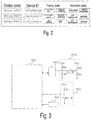
- Fig. 2 shows a presentation interface for information about results such as pairing and activation of the wireless secondary controllers in one example.
- the device Wireless RMC1 has been paired successfully and activated; the device Wireless RMC2 has been successfully paired but not activated; the device Wireless RMC3 has not been paired and not been activated.
- the wireless main controller 100 may furthermore receive a deactivation request signal inputted by a user for an activated wireless secondary controller 200, cancel receipt of a control message from the corresponding wireless secondary controller 200 according to an identifier of a wireless secondary controller 200 carried in the deactivation request signal, and filter a message from the wireless secondary controller 200; and moreover present deactivation result information.
- the wireless secondary controller 200 may receive a first sub-signal and a second sub-signal corresponding to a control signal by means of a control button having dual switch contacts, in order to prevent a single fault of the control button of the wireless secondary controller 200; wherein the first sub-signal may be a first digital control signal inputted via one switch contact of the control button, and the second sub-signal may be a second digital control signal obtained by conversion via an analog-to-digital conversion module of an analog control signal inputted via the other switch contact of the control button. Thereafter, the wireless secondary controller 200 may compare the first sub-signal and second sub-signal, and if the two are the same, carry an identifier of the wireless secondary controller 200 in the control signal and send this to the wireless main controller 100.
- the wireless main controller 100 may have multiple specific implementations of internal structure. Fig. 1 shows just one of these. As Fig. 1 shows, the wireless main controller 100 may comprise: a CT main control board 101, a wireless main control board 102 and a human-machine interaction module 103.
- the wireless main control board 102 is used for receiving a control signal from a wireless secondary controller 200, subjecting the control signal to a validity check according to an identifier of the wireless secondary controller 200 carried in the control signal, and supplying the control signal which has passed the check to the CT main control board 101.
- the CT main control board 101 is used for receiving a control signal from the wireless main control board 102, and performing corresponding operation control according to the control signal.
- the human-machine interaction module 103 is used for receiving a pairing request signal, and supplying the pairing request signal to the CT main control board 101; the pairing request signal comprises an identifier of a wireless secondary controller 200.
- the CT main control board 101 supplies the pairing request signal to the wireless main control board 102; and receives pairing result information fed back by the wireless main control board 102, and presents the pairing result information by means of the human-machine interaction module 103.
- the wireless main control board 102 sends a pairing instruction to the corresponding wireless secondary controller 200, and enters a pairing mode state, waits to receive a pairing confirmation signal from the wireless secondary controller 200, and if a pairing confirmation signal from the wireless secondary controller 200 is correctly received, determines that pairing with the wireless secondary controller 200 is successful, and otherwise determines that pairing with the wireless secondary controller 200 has failed, and feeds back pairing result information to the CT main control board 101; and upon determining that pairing with the wireless secondary controller 200 is successful, sends pairing result information indicating pairing success to the corresponding wireless secondary controller 200.
- the wireless main control board 102 may confirm that the control signal is a valid control signal if it is determined, on the basis of an identifier of the wireless secondary controller 200 carried in the control signal, that the wireless secondary controller has been successfully paired.
- the CT main control board 101 may furthermore present input prompt information for a pairing sequence code by means of the human-machine interaction module 103 and/or an external display screen; and moreover carries the pairing sequence code in the pairing request signal and supplies this to the wireless main control board 102; and when the received pairing result information fed back by the wireless main control board 102 indicates successful pairing, controls the human-machine interaction module 103 and/or the external display screen to stop displaying the input prompt information for the pairing sequence code.
- the pairing confirmation signal from the wireless secondary controller 200 comprises a pairing check code inputted by a user according to the pairing sequence code prompt information.
- the wireless main controller 102 After receiving the pairing confirmation signal from the wireless secondary controller 200, the wireless main controller 102 compares the pairing check code in the pairing confirmation signal with the pairing sequence code carried in the pairing request signal, and if the two are the same, determines that the pairing confirmation signal from the wireless secondary controller 200 has been correctly received.
- the wireless main control board 102 may furthermore carry the pairing sequence code in the pairing instruction and send this to the corresponding wireless secondary controller 200; and after receiving a pairing confirmation signal comprising a pairing check code from the wireless secondary controller 200, can compare the pairing check code in the pairing confirmation signal with the pairing sequence code carried in the pairing request signal, and if the two are the same, determines that the pairing confirmation signal from the wireless secondary controller 200 has been correctly received.
- the human-machine interaction module 103 may furthermore receive a cancel pairing request signal inputted by a user for a successfully paired wireless secondary controller 200, and supply the cancel pairing request signal to the CT main control board 101; the cancel pairing request signal comprises an identifier of a wireless secondary controller 200.
- the CT main control board 101 supplies the cancel pairing request signal to the wireless main control board 102; and receives cancel pairing result information fed back by the wireless main control board 102, and presents the cancel pairing result information by means of the human-machine interaction module 103.
- the wireless main control board 102 on the basis of an identifier in the cancel pairing request signal, cancels receipt of a control message from the corresponding wireless secondary controller 200, and filters a message from the wireless secondary controller 200.
- the human-machine interaction module 103 may furthermore receive an activation request signal inputted by a user for a successfully paired wireless secondary controller, and supply the activation request signal to the CT main control board 101; the activation request signal comprises an identifier of a wireless secondary controller 200.
- the CT main control board 101 may furthermore supply the activation request signal to the wireless main control board 102; and receives activation result information fed back by the wireless main control board 102, and presents the activation result information by means of the human-machine interaction module.
- the wireless main control board 102 On the basis of the identifier in the activation request signal, the wireless main control board 102 furthermore waits to receive a control message from the corresponding wireless secondary controller, and filters a message from another wireless secondary controller; and after receiving a control signal from a wireless secondary controller 200, confirms that the control signal is a valid control signal if it is determined, on the basis of an identifier of the wireless secondary controller 200 carried in the control signal, that the wireless secondary controller 200 has been paired successfully and activated.
- the human-machine interaction module 103 may furthermore receive a deactivation request signal inputted by a user for an activated wireless secondary controller 200, and supply the deactivation request signal to the CT main control board 101; the deactivation request signal comprises an identifier of a wireless secondary controller 200.
- the CT main control board 101 supplies the deactivation request signal to the wireless main control board 102; and receives deactivation result information fed back by the wireless main control board 102, and presents the deactivation result information by means of the human-machine interaction module 103.
- the wireless main control board 102 on the basis of an identifier in the deactivation request signal, cancels receipt of a control message from the corresponding wireless secondary controller 200, and filters a message from the wireless secondary controller 200.
- the internal structure of the wireless main control board 102 may have multiple specific implementations. Fig. 1 shows just one of these. As Fig. 1 shows, the wireless main control board 102 may comprise: a wireless transceiving processor 1021, a microprocessor 1022, a physical layer interface 1023 and a power supply adaptor module 1024.
- the wireless transceiving processor 1021 and the microprocessor 1022 are correspondingly connected via corresponding serial peripheral interface (SPI) pins and input/output (I/O) pins; the microprocessor 1022 is electrically connected to the CT main control board 101 via the physical layer interface 1023; the microprocessor 1022 and a power supply interface of the wireless transceiving processor 1021 are each connected to a power supply line of the CT main control board 101 via the power supply adaptor module 1024.
- SPI serial peripheral interface
- I/O input/output
- the wireless transceiving processor 1021 is mainly used to accomplish data processing of a wireless transmission protocol; the microprocessor 1022 is mainly used to accomplish data conversion between the wireless transceiving processor 1021 and CT main control board 101. In addition, the check processing of the control signal is mainly accomplished by the microprocessor 1022.
- the internal structure of the wireless secondary controller 200 may also have multiple specific implementations.
- Fig. 1 shows just one of these.
- the wireless secondary controller 200 may comprise: a human-machine interface module 201, a wireless transceiving processor 202 and a power supply module 203.
- the human-machine interface module 201 and wireless transceiving processor 202 are correspondingly connected via SPI pins and/or I/O pins.
- the human-machine interface module 201 is used for receiving a control signal, and supplying the control signal to the wireless transceiving processor 202.
- the wireless transceiving processor 202 is used for carrying an identifier of the wireless secondary controller 200 in the control signal, and sending the control signal carrying the identifier to the wireless main controller 100.
- the power supply module 203 is used for supplying power to the human-machine interface module 201 and the wireless transceiving processor 202 by means of a battery.
- the human-machine interface module 201 may furthermore receive a pairing confirmation signal inputted by a user before receiving the control signal, and supply the pairing confirmation signal to the wireless transceiving processor 202.
- the wireless transceiving processor 202 is furthermore used for receiving a pairing instruction from the wireless main controller 100, and entering a pairing mode state, waiting to receive a pairing confirmation signal from the human-machine interface module 201, and after receiving the pairing confirmation signal, sending the pairing confirmation signal to the wireless main controller 100; and if a pairing success message is received from the wireless main controller 100, entering an operating mode state.
- the wireless main controller 100 if the wireless main controller 100 presents input prompt information for a pairing sequence code by means of its own human-machine interaction module 103 or an external display screen, then the pairing confirmation signal received by the human-machine interface module 201 may comprise a pairing check code inputted by a user according to the input prompt information for the pairing sequence code.
- the wireless transceiving processor 202 of the wireless secondary controller 200 may furthermore supply the pairing instruction to the human-machine interface module 201, and a display unit of the human-machine interface module 201 presents the pairing sequence code carried in the pairing instruction.
- the pairing confirmation signal received by the human-machine interface module 201 may comprise a pairing check code inputted by a user according to the pairing sequence code.
- each control button may be a control button having dual switch contacts, in order to prevent a single fault of the control button, so that a first sub-signal and a second sub-signal corresponding to the same signal can be respectively received via pathways in which the two contacts of the control button are located; wherein the first sub-signal may be a first digital signal inputted via one switch contact of the control button, and the second sub-signal may be a second digital signal obtained by conversion via an analog-to-digital conversion module of an analog control signal inputted via the other switch contact of the control button.
- the wireless transceiving processor 202 may compare the first sub-signal and second sub-signal, and if the two are the same, carry an identifier of the wireless secondary controller 200 in the signal and send this to the wireless main controller 100.
- Fig. 3 shows a structural schematic diagram of a dual-contact control button of the human-machine interface module in one example of the present invention.
- the human-machine interface module 201 may comprise: multiple control buttons K1 (only one control button is shown in Fig. 3 ), and, corresponding to each control button K1, a first interface circuit 2011, a second interface circuit 2012 and an analog-to-digital conversion module 2013.
- Each control button K1 comprises two independent switch contacts K1_A, K1_B, wherein one switch contact K1_A is connected to an I/O interface pin of the wireless transceiving processor 202 via the first interface circuit 2011, and the other switch contact K1_B is connected to an SPI pin of the wireless transceiving processor 202 via the second interface circuit 2012 and the analog-to-digital conversion module 2013.
- the first interface circuit 2011 comprises a first resistor R1 which has one end connected to a HIGH level and another end connected to one end of the switch contact K1_A, the other end of the switch contact K1_A being connected to ground; a non-grounded end of the switch contact K1_A is connected to an I/O interface pin of the wireless transceiving processor 202.
- the second interface circuit 2012 comprises a second resistor R2, a third resistor R3, a fourth resistor R4 and a fifth resistor R5.
- the second resistor R2 has one end connected to a HIGH level and another end connected to one end of the switch contact K1_B and one end of the third resistor R3; the other end of the third resistor R3 is connected to ground; the fourth resistor R4 has one end connected to a HIGH level and another end connected to the other end of the switch contact K1_B and one end of the fifth resistor R5; the other end of the fifth resistor R5 is connected to ground; that end of the switch contact K1_B which is connected to the fourth resistor R4 is connected to an SPI pin of the wireless transceiving processor 202.
- the switch contact K1_A is closed, and the wireless transceiving processor 202 receives a LOW signal; when the switch contact K1_A is opened, the wireless transceiving processor 202 receives a HIGH signal from the first interface circuit 2011.
- the switch contact K1_B is closed, and the analog-to-digital conversion module 2013 acquires a first analog signal value from the second interface circuit 2012; when the switch contact K1_B is closed, the analog-to-digital conversion module 2013 acquires a second analog signal value from the second interface circuit 2012.
- the analog-to-digital conversion module 2013 converts the analog signal acquired to a digital signal and then supplies this to the wireless transceiving processor 202; the wireless transceiving processor 202 can determine whether K1_B is open or closed by means of the value read.
- the processor only deems the state of the button to be valid when the states of K1_A and K1_B read by the wireless transceiving processor 202 are the same; otherwise, the processor deems the state of the button to be invalid.
- the entry of the wireless main controller 100 into a pairing mode state may consist of the wireless main controller 100 starting a pairing timer; the range of values which may be chosen for the pairing timer may be 30 - 120 seconds, etc., e.g. a value of 30 seconds, 1 minute, 1.5 minutes or 2 minutes etc. may be chosen. If no pairing confirmation signal sent from a wireless secondary controller 200 has been received within the time limit, then it can be determined that the current pairing has failed.
- the entry of the wireless secondary controller 200 into a pairing mode state may consist of the wireless secondary controller 200 starting a pairing timer; the range of values which may be chosen for the pairing timer may also be 30 - 120 seconds, etc., e.g. a value of 30 seconds, 1 minute, 1.5 minutes or 2 minutes etc. may be chosen. If no pairing confirmation signal inputted by a user has been received within the time limit, then it can be determined that the current pairing has failed.
- the CT machine in an embodiment of the present invention may comprise a wireless control system implemented in any one of the abovementioned forms; or a wireless main controller implemented in any one of the abovementioned forms.
- the wireless control system in embodiments of the present invention has been described in detail above; the wireless control method in embodiments of the present invention is described in detail below.
- the wireless control method in embodiments of the present invention may be applied to the wireless control system described above.
- Fig. 4 is a demonstrative flow chart of a wireless control method in an embodiment of the present invention.
- the wireless control method may be applied in a wireless control system comprising a wireless main controller and at least one wireless secondary controller. As Fig. 4 shows, the method may comprise the following steps:
- the wireless secondary controller may receive a first sub-signal and a second sub-signal corresponding to the control signal by means of a control button having dual switch contacts; the first sub-signal is a first digital control signal inputted via one switch contact of the control button, and the second sub-signal is a second digital control signal obtained by conversion via an analog-to-digital conversion module of an analog control signal inputted via the other switch contact of the control button; the wireless secondary controller compares the first sub-signal and second sub-signal, and if the two are the same, carries an identifier of the wireless secondary controller in the control signal.
- Step 502 the wireless main controller receives a control signal from the wireless secondary controller, subjects the control signal to a validity check according to the identifier of the wireless secondary controller carried in the control signal, and if the check is passed, performs corresponding operation control according to the control signal.
- Fig. 5 is a demonstrative flow chart of another wireless control method in an embodiment of the present invention.
- the wireless control method may be applied in a wireless control system comprising a wireless main controller and at least one wireless secondary controller. As Fig. 5 shows, the method may comprise the following steps:
- the wireless main controller may present a pairing sequence code by means of the wireless main controller or an external display screen; or the wireless main controller carries a pairing sequence code in a pairing instruction and sends this to the wireless secondary controller.
- Step 602 the wireless secondary controller receives the pairing instruction, enters a pairing mode state, receives a pairing confirmation signal inputted by a user, and sends the pairing confirmation signal to the wireless main controller.
- the user when inputting the pairing confirmation signal, may input a pairing check code corresponding to the pairing sequence code according to the information presented.
- the wireless main controller carries a pairing sequence code in a pairing instruction and sends this to the wireless secondary controller
- the wireless secondary controller may present the pairing sequence code by means of its own display unit, so that the user, when inputting the pairing confirmation signal, may input a pairing check code corresponding to the pairing sequence code according to the information presented.
- Step 603 the wireless main controller, if it determines that a pairing confirmation signal from the wireless secondary controller is correctly received, determines that pairing with the wireless secondary controller is successful; otherwise, it determines that pairing with the wireless secondary controller has failed, and presents information about the result of pairing with the wireless secondary controller; and when pairing is successful, sends a pairing success message to the wireless secondary controller.
- the wireless main controller after receiving the pairing confirmation signal from the wireless secondary controller, may compare the pairing check code in the pairing confirmation signal with the pairing sequence code, and when the two are the same, determine that the pairing confirmation signal from the wireless secondary controller has been correctly received.
- Step 604 the wireless secondary controller, if it receives a pairing success message from the wireless main controller, enters an operating mode state.
- Step 605 a wireless secondary controller receives a control signal, carries an identifier of the wireless secondary controller in the control signal, and sends the control signal carrying the identifier to a wireless main controller; the wireless secondary controller is one of the at least one wireless secondary controllers.
- the wireless secondary controller may receive a first sub-signal and a second sub-signal corresponding to the control signal by means of a control button having dual switch contacts; the first sub-signal is a first digital control signal inputted via one switch contact of the control button, and the second sub-signal is a second digital control signal obtained by conversion via an analog-to-digital conversion module of an analog control signal inputted via the other switch contact of the control button; the wireless secondary controller compares the first sub-signal and second sub-signal, and if the two are the same, carries an identifier of the wireless secondary controller in the control signal.
- Step 606 the wireless main controller receives a control signal from the wireless secondary controller, and determines whether the wireless secondary controller has been paired successfully according to the identifier of the wireless secondary controller carried in the control signal, and if it has been, confirms that the control signal is a valid control signal, and performs corresponding operation control according to the control signal.
- the wireless main controller may furthermore receive a cancel pairing request signal inputted by a user for a successfully paired wireless secondary controller, cancel receipt of a control message from the corresponding wireless secondary controller according to an identifier of the wireless secondary controller carried in the cancel pairing request signal, and filter a message from the wireless secondary controller; and moreover present cancel pairing result information.
- Fig. 6 is a demonstrative flow chart of another wireless control method in an embodiment of the present invention.
- the wireless control method may be applied in a wireless control system comprising a wireless main controller and at least one wireless secondary controller. As Fig. 6 shows, the method may comprise the following steps:
- the wireless secondary controller may receive a first sub-signal and a second sub-signal corresponding to the control signal by means of a control button having dual switch contacts; the first sub-signal is a first digital control signal inputted via one switch contact of the control button, and the second sub-signal is a second digital control signal obtained by conversion via an analog-to-digital conversion module of an analog control signal inputted via the other switch contact of the control button; the wireless secondary controller compares the first sub-signal and second sub-signal, and if the two are the same, carries an identifier of the wireless secondary controller in the control signal.
- Step 707 the wireless main controller receives a control signal from the wireless secondary controller, and determines whether the wireless secondary controller has been paired successfully according to the identifier of the wireless secondary controller carried in the control signal, and if it has been, confirms that the control signal is a valid control signal, and performs corresponding operation control according to the control signal.
- the wireless main controller may furthermore receive a deactivation request signal inputted by a user for an activated wireless secondary controller, cancel receipt of a control message from the corresponding wireless secondary controller according to an identifier of a wireless secondary controller carried in the deactivation request signal, and filter a message from the wireless secondary controller; and moreover present deactivation result information.
- the CT machine in embodiments of the present invention has been provided with a wireless control system comprising a wireless main controller and at least one wireless secondary controller
- the wireless main controller receives and identifies a control message from a corresponding wireless secondary controller through a wireless channel, and can realize corresponding operation control, such that the wireless secondary controllers serving as CT machine control components can be arranged as required, and no longer be subject to the restrictions of wired connections.
- the provision of independent switch contacts on a control button side of the wireless secondary controller enables the same control signal to be independently sent to a wireless transceiving processor of the wireless secondary controller via channels corresponding to different switch points, so that a single fault of the button can be avoided, thereby further ensuring the operational safety of the CT machine.
Landscapes
- Engineering & Computer Science (AREA)
- Health & Medical Sciences (AREA)
- Life Sciences & Earth Sciences (AREA)
- Medical Informatics (AREA)
- Heart & Thoracic Surgery (AREA)
- Animal Behavior & Ethology (AREA)
- Biophysics (AREA)
- Nuclear Medicine, Radiotherapy & Molecular Imaging (AREA)
- Optics & Photonics (AREA)
- Pathology (AREA)
- Radiology & Medical Imaging (AREA)
- Biomedical Technology (AREA)
- Physics & Mathematics (AREA)
- Molecular Biology (AREA)
- Surgery (AREA)
- High Energy & Nuclear Physics (AREA)
- General Health & Medical Sciences (AREA)
- Public Health (AREA)
- Veterinary Medicine (AREA)
- Computer Networks & Wireless Communication (AREA)
- Signal Processing (AREA)
- Human Computer Interaction (AREA)
- Pulmonology (AREA)
- Theoretical Computer Science (AREA)
- Computer Security & Cryptography (AREA)
- Selective Calling Equipment (AREA)
Abstract
Description
- The present invention relates to the field of medical equipment, in particular a CT machine wireless controller, a wireless control system and a CT machine.
- In certain medical devices, such as X-Ray computed tomography (CT) machines, there will generally be at least one human machine interface (HMI) control component, to realize control of the operation of the medical device. At present, each HMI control component is directly connected to a motherboard of the medical device by wired connection.
- Thus, restricted by the length and topological structure of wired cables, HMI control components connected in a wired fashion may only be arranged in specific positions. For example, in CT machines, it is generally necessary to perform control at different positions in response to different control demands.
- When it is necessary to control X-rays to perform exposure imaging, the operator must generally perform exposure control in an operating room outside the imaging room, to prevent the operator from being subjected to unnecessary X-ray radiation; when it is necessary to control the X-ray source or patient table to perform complex movement, the operator must generally perform movement control beside the imaging device, to better observe whether movement positions are suitable, but if it is only necessary to control the X-ray source or patient table to perform simple movement, the operator may also perform movement control in the operating room. To fulfil different control demands, it is generally necessary to dispose multiple wired HMI control components at different positions. At present, these HMI control components may include control boxes, gantry control panels and foot-operated controllers, etc.
- To better promote the rational deployment of resources, persons skilled in the art are still making efforts to seek other ways of realizing HMI control components.
- In view of the above, the present invention on the one hand proposes a wireless controller, and on the other hand proposes a wireless control system and a CT machine, for the purpose of facilitating the rational arrangement of control components.
- A wireless main controller proposed in an embodiment of the present invention comprises: a CT main control board and a wireless main control board; wherein the wireless main control board is used for receiving a control signal from a wireless secondary controller, subjecting the control signal to a validity check according to an identifier of the wireless secondary controller carried in the control signal, and supplying the control signal which has passed the check to the CT main control board; the CT main control board is used for receiving a control signal from the wireless main control board, and performing corresponding control according to the control signal.
- In one embodiment, further included is: a human-machine interaction module, for receiving a pairing request signal, and supplying the pairing request signal to the CT main control board; the pairing request signal comprises an identifier of a wireless secondary controller; the CT main control board is further used for supplying the pairing request signal to the wireless main control board after receiving the pairing request signal; and receiving pairing result information fed back by the wireless main control board, and presenting the pairing result information by means of the human-machine interaction module; the wireless main control board is further used for sending a pairing instruction to the corresponding wireless secondary controller according to the identifier in the pairing request signal, and entering a pairing mode state, waiting to receive a pairing confirmation signal from the wireless secondary controller, and if a pairing confirmation signal from the wireless secondary controller is correctly received, determining that pairing with the wireless secondary controller is successful; otherwise determining that pairing with the wireless secondary controller has failed, and feeding back pairing result information to the CT main control board; and upon determining that pairing with the wireless secondary controller is successful, sending pairing result information indicating pairing success to the corresponding wireless secondary controller; after receiving a control signal from the wireless secondary controller, the wireless main control board confirms that the control signal is a valid control signal if it is determined, on the basis of the identifier of the wireless secondary controller carried in the control signal, that the wireless secondary controller has been successfully paired.
- In one embodiment, the CT main control board, after receiving the pairing request signal, is further used for presenting input prompt information for a pairing sequence code by means of the human-machine interaction module and/or an external display screen; and moreover carrying the pairing sequence code in the pairing request signal and supplying this to the wireless main control board; and when received pairing result information fed back by the wireless main control board indicates successful pairing, controlling the human-machine interaction module and/or the external display screen to stop displaying the input prompt information for the pairing sequence code; the pairing confirmation signal comprises a pairing check code corresponding to the pairing sequence code prompt information; the wireless main control board, after receiving the pairing confirmation signal from the wireless secondary controller, compares the pairing check code in the pairing confirmation signal with the pairing sequence code carried in the pairing request signal, and when the two are the same, determines that the pairing confirmation signal from the wireless secondary controller has been correctly received.
- In one embodiment, the CT main control board, after receiving the pairing request signal, is further used for carrying a pairing sequence code in the pairing request signal, and supplying the pairing request signal carrying the pairing sequence code to the wireless main control board; the wireless main control board is further used for carrying the pairing sequence code in the pairing instruction and sending this to the corresponding wireless secondary controller; and after receiving a pairing confirmation signal comprising a pairing check code from the wireless secondary controller, comparing the pairing check code in the pairing confirmation signal with the pairing sequence code carried in the pairing request signal, and if the two are the same, determining that the pairing confirmation signal from the wireless secondary controller has been correctly received.
- In one embodiment, the human-machine interaction module is further used for receiving an activation request signal for a successfully paired wireless secondary controller, and supplying the activation request signal to the CT main control board; the activation request signal comprises an identifier of a wireless secondary controller; the CT main control board is further used for supplying the activation request signal to the wireless main control board after receiving the activation request signal; and receiving activation result information fed back by the wireless main control board, and presenting the activation result information by means of the human-machine interaction module; after receiving a control signal from a wireless secondary controller, the wireless main control board is further used for confirming that the control signal is a valid control signal if it is determined, on the basis of the identifier of the wireless secondary controller carried in the control signal, that the wireless secondary controller has been paired successfully and activated.
- A wireless secondary controller provided in an embodiment of the present invention comprises: a human-machine interface module and a wireless transceiving processor; wherein the human-machine interface module and the wireless transceiving processor are correspondingly connected via serial peripheral interface pins and/or input/output pins; the human-machine interface module is used for receiving a control signal, and supplying the control signal to the wireless transceiving processor; the wireless transceiving processor is used for carrying an identifier of the wireless secondary controller in the control signal, and transmitting the control signal carrying the identifier.
- In one embodiment, the human-machine interface module is further used for receiving a pairing confirmation signal before receiving the control signal, and supplying the pairing confirmation signal to the wireless transceiving processor; the wireless transceiving processor is further used for receiving a pairing instruction from the wireless main controller, and entering a pairing mode state, receiving the pairing confirmation signal from the human-machine interface module, and transmitting the pairing confirmation signal; and entering an operating mode state if a pairing success message from the wireless main controller is received.
- In one embodiment, the pairing confirmation signal comprises a pairing check code.
- In one embodiment, the wireless transceiving processor is further used for supplying the pairing instruction to the human-machine interface module, and a display unit of the human-machine interface module presents the pairing sequence code carried in the pairing instruction.
- In one embodiment, the human-machine interface module comprises: multiple control buttons, and corresponding to each control button, a first interface circuit, a second interface circuit and an analog-to-digital conversion module; wherein each control button comprises two independent switch contacts, wherein one switch contact is connected to an input/output interface pin of the wireless transceiving processor via a first interface circuit, and the other switch contact is connected to a serial peripheral interface pin of the wireless transceiving processor via a second interface circuit and an analog-to-digital conversion module; the wireless transceiving processor, before carrying the identifier of the wireless secondary controller in the control signal, is further used for comparing a control signal received via the input/output interface pin with a control signal received via the serial peripheral interface pin, and if the two are the same, carrying the identifier of the wireless secondary controller in the control signal.
- A wireless control system proposed in an embodiment of the present invention comprises: the wireless main controller described above and the wireless secondary controller described above.
- A CT machine proposed in an embodiment of the present invention comprises the abovementioned wireless control system; or the wireless main controller described above.
- It can be seen from the solution above that since the CT machine in embodiments of the present invention has been provided with a wireless control system comprising a wireless main controller and at least one wireless secondary controller, the wireless main controller receives and identifies a control message from a corresponding wireless secondary controller through a wireless channel, and can realize corresponding operation control, such that the wireless secondary controllers serving as CT machine control components can be arranged as required, and no longer be subject to the restrictions of wired connections.
- In addition, by performing a paired connection with corresponding wireless secondary controllers one by one, the reliability of data communication with corresponding wireless secondary controllers can be ensured.
- Moreover, through the use of verification by comparison of a pairing sequence code and a pairing check code, the reliability of data communication with corresponding wireless secondary controllers can be further ensured.
- In addition, by controlling a paired wireless secondary controller to enter an activation state, the operational safety of the CT machine can be further ensured.
- Furthermore, the provision of independent switch contacts on a control button side of the wireless secondary controller enables the same control signal to be independently sent to a wireless transceiving processor of the wireless secondary controller via channels corresponding to different switch points, so that a single fault of the button can be avoided, thereby further ensuring the operational safety of the CT machine.
- Preferred embodiments of the present invention are described in detail below with reference to the accompanying drawings, to give those skilled in the art a clearer understanding of the abovementioned and other features and advantages of the present invention. Drawings:
-
Fig. 1 is a structural schematic diagram of a wireless control system in an embodiment of the present invention. -
Fig. 2 is a presentation interface for information about results such as pairing and activation of the wireless secondary controllers in one example of the present invention. -
Fig. 3 is a structural schematic diagram of a dual-contact control button of the human-machine interface module in one example of the present invention. -
Fig. 4 is a demonstrative flow chart of a wireless control method in an embodiment of the present invention. -
Fig. 5 is a demonstrative flow chart of another wireless control method in an embodiment of the present invention. -
Fig. 6 is a demonstrative flow chart of another wireless control method in an embodiment of the present invention. - Key to the drawings:
Label Meaning 100 wireless main controller 101 CT main control board 102 wireless main control board 1021 wireless transceiving processor 1022 microprocessor 1023 physical layer interface 1024 power supply adaptor module 103 human- machine interaction module 200 wireless secondary controller 201 human- machine interface module 2011 first interface circuit 2012 second interface circuit 2013 analog-to- digital conversion module 202 wireless transceiving processor 203 power supply module K1 control button K1_A, K1_B switch contacts R1, R2, R3, R4, R5, R6 resistors 501, 605, 706 wireless secondary controller sends control signal carrying its own identifier to wireless main controller 502, 606, 707 wireless main controller subjects the control signal to validity check, and if the check is passed, performs corresponding operation control according to the control signal 601, 701 wireless main controller sends a pairing instruction to corresponding wireless secondary controller 602, 702 wireless secondary controller sends pairing confirmation signal to wireless main controller 603, 703 wireless main controller, when it correctly receives pairing confirmation signal from the wireless secondary controller, sends pairing success message to the wireless secondary controller 604, 704 wireless secondary controller, if it receives pairing success message from wireless main controller, enters operating mode state 705 wireless main controller activates control of communication with a wireless secondary controller - In order to clarify the object, technical solution and advantages of the present invention, the present invention is explained in further detail below by way of embodiments.
-
Fig. 1 is a structural schematic diagram of a wireless control system in an embodiment of the present invention. AsFig. 1 shows, the wireless control system may comprise: a wirelessmain controller 100 and at least one wirelesssecondary controller 200. - Each wireless
secondary controller 200 is used for receiving a control signal, carrying an identifier of the wirelesssecondary controller 200 in the control signal, and transmitting the control signal carrying the identifier. Each wireless secondary controller has one unique identifier (ID) number. - The at least one wireless
secondary controller 200 may comprise at least two wirelesssecondary controllers 200 with exactly the same functions or partly the same functions or completely different functions. For example, a manually-controlled wireless secondary controller and a foot-operated wireless secondary controller may be included. Alternatively, two manually-controlled wireless secondary controllers may be included. Alternatively, two manually-controlled wireless secondary controllers and a foot-operated wireless secondary controller etc. may be included. - The wireless
main controller 100 is used for receiving a control signal from the wirelesssecondary controller 200, subjecting the control signal to a validity check according to an identifier of the wirelesssecondary controller 200 carried in the control signal, and if the check is passed, performing corresponding operation control according to the control signal. - Furthermore, when there is more than one wireless
secondary controller 200, in order to better receive control signals from eachsecondary controller 200, in this embodiment, the wirelesssecondary controllers 200 may furthermore be paired in advance. - Correspondingly, the wireless
main controller 100 may receive a pairing request signal of a user for a wirelesssecondary controller 200, the pairing request signal comprising an identifier of a wireless secondary controller; on the basis of the identifier in the pairing request signal, the corresponding wirelesssecondary controller 200 sends a pairing instruction, and enters a pairing mode state; if it is determined that a pairing confirmation signal from the wirelesssecondary controller 200 is received correctly, then it is determined that pairing with the wirelesssecondary controller 200 is successful; otherwise, it is determined that pairing with the wirelesssecondary controller 200 has failed, and information about the result of pairing with the wirelesssecondary controller 200 is presented; moreover, when pairing is successful, a pairing success message is sent to a wirelesssecondary controller 200. - A wireless
secondary controller 200 receives the pairing instruction, enters a pairing mode state, waits to receive a pairing confirmation signal inputted by a user, and sends the pairing confirmation signal to the wirelessmain controller 100; if a pairing success message is received from the wirelessmain controller 100, then an operating mode state is entered. - In an embodiment of the present invention, the pairing confirmation signal may be a pairing confirmation signal inputted by a user by clicking on a confirmation button, or may be a pairing confirmation signal inputted by a user according to a specific indication of the pairing instruction, or may be a pairing confirmation signal inputted by a user according to a specific indication of the wireless
main controller 100. - When pairing is performed, the wireless
main controller 100 may generate a pairing sequence code, e.g. a random sequence code; or may set at least one pairing sequence code in advance, and select different pairing sequence codes for different communication or different wirelesssecondary controllers 200, or may universally employ one identical pairing sequence code, etc. and intimate the pairing sequence code to a user of a corresponding wirelesssecondary controller 200, so that the user inputs a pairing check code corresponding to the pairing sequence code, and then the wirelesssecondary controller 200 can carry the pairing check code in pairing confirmation information and send this to the wirelessmain controller 100, such that the wirelessmain controller 100, after receiving the pairing confirmation signal, can compare the pairing check code in the pairing confirmation signal with the pairing sequence code, and if the two are the same, determine that the pairing confirmation signal from the wirelesssecondary controller 200 has been correctly received. - When the pairing sequence code is intimated to a user of a corresponding wireless
secondary controller 200, the wirelessmain controller 100 may display the pairing sequence code by means of its own display unit or by means of an external display screen, for the purpose of reminding the user to input the pairing sequence code on the corresponding wirelesssecondary controller 200, so as to generate a corresponding pairing check code. The external display screen may be a display screen on the CT gantry (GDP, Gantry Display Panel). Alternatively, the wirelessmain controller 100 may also carry the pairing sequence code in a pairing instruction and send this to a corresponding wirelesssecondary controller 200, and the pairing sequence code is presented by a display unit of the wirelesssecondary controller 200. - For example, prompt information is: "Would the user please press the sequence of button 1,
button 2 and button 3 in order within 30 s and click on the wireless secondary controller (setup ID: 1106135120160112)". - In addition, the wireless
main controller 100 may furthermore receive a cancel pairing request signal inputted by a user for a successfully paired wirelesssecondary controller 200, cancel receipt of a control message from the corresponding wirelesssecondary controller 200 according to an identifier of the wirelesssecondary controller 200 carried in the cancel pairing request signal, and filter a message from the wirelesssecondary controller 200; and moreover present cancel pairing result information. - In addition, in an embodiment of the present invention, to further ensure operation safety, an activation state may also be set for successfully paired wireless
secondary controllers 200. - Correspondingly, the wireless
main controller 100 may furthermore receive an activation request signal inputted by a user for a successfully paired wirelesssecondary controller 200, wait to receive a control message from the corresponding wirelesssecondary controller 200 according to an identifier of a wirelesssecondary controller 200 carried in the activation request signal, and filter a message from another wirelesssecondary controller 200; and moreover present activation result information. - After receiving a control signal from a wireless
secondary controller 200, the wirelessmain controller 100 may determine, according to an identifier of the wirelesssecondary controller 200 carried in the control signal, whether the wirelesssecondary controller 200 has been paired successfully and activated, and if it has been, confirm that the control signal is a valid control signal. -
Fig. 2 shows a presentation interface for information about results such as pairing and activation of the wireless secondary controllers in one example. The device Wireless RMC1 has been paired successfully and activated; the device Wireless RMC2 has been successfully paired but not activated; the device Wireless RMC3 has not been paired and not been activated. - In addition, the wireless
main controller 100 may furthermore receive a deactivation request signal inputted by a user for an activated wirelesssecondary controller 200, cancel receipt of a control message from the corresponding wirelesssecondary controller 200 according to an identifier of a wirelesssecondary controller 200 carried in the deactivation request signal, and filter a message from the wirelesssecondary controller 200; and moreover present deactivation result information. - In an embodiment of the present invention, in the case where a wireless
secondary controller 200 comprises a control button, the wirelesssecondary controller 200 may receive a first sub-signal and a second sub-signal corresponding to a control signal by means of a control button having dual switch contacts, in order to prevent a single fault of the control button of the wirelesssecondary controller 200; wherein the first sub-signal may be a first digital control signal inputted via one switch contact of the control button, and the second sub-signal may be a second digital control signal obtained by conversion via an analog-to-digital conversion module of an analog control signal inputted via the other switch contact of the control button. Thereafter, the wirelesssecondary controller 200 may compare the first sub-signal and second sub-signal, and if the two are the same, carry an identifier of the wirelesssecondary controller 200 in the control signal and send this to the wirelessmain controller 100. - In embodiments of the present invention, the wireless
main controller 100 may have multiple specific implementations of internal structure.Fig. 1 shows just one of these. AsFig. 1 shows, the wirelessmain controller 100 may comprise: a CTmain control board 101, a wirelessmain control board 102 and a human-machine interaction module 103. - The wireless
main control board 102 is used for receiving a control signal from a wirelesssecondary controller 200, subjecting the control signal to a validity check according to an identifier of the wirelesssecondary controller 200 carried in the control signal, and supplying the control signal which has passed the check to the CTmain control board 101. - The CT
main control board 101 is used for receiving a control signal from the wirelessmain control board 102, and performing corresponding operation control according to the control signal. - If it is necessary to perform pairing with a wireless
secondary controller 200 before performing formal control communication, the human-machine interaction module 103 is used for receiving a pairing request signal, and supplying the pairing request signal to the CTmain control board 101; the pairing request signal comprises an identifier of a wirelesssecondary controller 200. - Correspondingly, after receiving the pairing request signal, the CT
main control board 101 supplies the pairing request signal to the wirelessmain control board 102; and receives pairing result information fed back by the wirelessmain control board 102, and presents the pairing result information by means of the human-machine interaction module 103. On the basis of the identifier in the pairing request signal, the wirelessmain control board 102 sends a pairing instruction to the corresponding wirelesssecondary controller 200, and enters a pairing mode state, waits to receive a pairing confirmation signal from the wirelesssecondary controller 200, and if a pairing confirmation signal from the wirelesssecondary controller 200 is correctly received, determines that pairing with the wirelesssecondary controller 200 is successful, and otherwise determines that pairing with the wirelesssecondary controller 200 has failed, and feeds back pairing result information to the CTmain control board 101; and upon determining that pairing with the wirelesssecondary controller 200 is successful, sends pairing result information indicating pairing success to the corresponding wirelesssecondary controller 200. - After receiving a control signal from a wireless
secondary controller 200, the wirelessmain control board 102 may confirm that the control signal is a valid control signal if it is determined, on the basis of an identifier of the wirelesssecondary controller 200 carried in the control signal, that the wireless secondary controller has been successfully paired. - In one embodiment, after receiving the pairing request signal, the CT
main control board 101 may furthermore present input prompt information for a pairing sequence code by means of the human-machine interaction module 103 and/or an external display screen; and moreover carries the pairing sequence code in the pairing request signal and supplies this to the wirelessmain control board 102; and when the received pairing result information fed back by the wirelessmain control board 102 indicates successful pairing, controls the human-machine interaction module 103 and/or the external display screen to stop displaying the input prompt information for the pairing sequence code. - Correspondingly, the pairing confirmation signal from the wireless
secondary controller 200 comprises a pairing check code inputted by a user according to the pairing sequence code prompt information. - After receiving the pairing confirmation signal from the wireless
secondary controller 200, the wirelessmain controller 102 compares the pairing check code in the pairing confirmation signal with the pairing sequence code carried in the pairing request signal, and if the two are the same, determines that the pairing confirmation signal from the wirelesssecondary controller 200 has been correctly received. - In another embodiment, after the CT
main control board 101 supplies the pairing request signal carrying the pairing sequence code to the wirelessmain control board 102, the wirelessmain control board 102 may furthermore carry the pairing sequence code in the pairing instruction and send this to the corresponding wirelesssecondary controller 200; and after receiving a pairing confirmation signal comprising a pairing check code from the wirelesssecondary controller 200, can compare the pairing check code in the pairing confirmation signal with the pairing sequence code carried in the pairing request signal, and if the two are the same, determines that the pairing confirmation signal from the wirelesssecondary controller 200 has been correctly received. - In addition, the human-
machine interaction module 103 may furthermore receive a cancel pairing request signal inputted by a user for a successfully paired wirelesssecondary controller 200, and supply the cancel pairing request signal to the CTmain control board 101; the cancel pairing request signal comprises an identifier of a wirelesssecondary controller 200. Correspondingly, after receiving the cancel pairing request signal, the CTmain control board 101 supplies the cancel pairing request signal to the wirelessmain control board 102; and receives cancel pairing result information fed back by the wirelessmain control board 102, and presents the cancel pairing result information by means of the human-machine interaction module 103. The wirelessmain control board 102, on the basis of an identifier in the cancel pairing request signal, cancels receipt of a control message from the corresponding wirelesssecondary controller 200, and filters a message from the wirelesssecondary controller 200. - In another embodiment, the human-
machine interaction module 103 may furthermore receive an activation request signal inputted by a user for a successfully paired wireless secondary controller, and supply the activation request signal to the CTmain control board 101; the activation request signal comprises an identifier of a wirelesssecondary controller 200. - After receiving the activation request signal, the CT
main control board 101 may furthermore supply the activation request signal to the wirelessmain control board 102; and receives activation result information fed back by the wirelessmain control board 102, and presents the activation result information by means of the human-machine interaction module. - On the basis of the identifier in the activation request signal, the wireless
main control board 102 furthermore waits to receive a control message from the corresponding wireless secondary controller, and filters a message from another wireless secondary controller; and after receiving a control signal from a wirelesssecondary controller 200, confirms that the control signal is a valid control signal if it is determined, on the basis of an identifier of the wirelesssecondary controller 200 carried in the control signal, that the wirelesssecondary controller 200 has been paired successfully and activated. - In addition, the human-
machine interaction module 103 may furthermore receive a deactivation request signal inputted by a user for an activated wirelesssecondary controller 200, and supply the deactivation request signal to the CTmain control board 101; the deactivation request signal comprises an identifier of a wirelesssecondary controller 200. Correspondingly, after receiving the deactivation request signal, the CTmain control board 101 supplies the deactivation request signal to the wirelessmain control board 102; and receives deactivation result information fed back by the wirelessmain control board 102, and presents the deactivation result information by means of the human-machine interaction module 103. The wirelessmain control board 102, on the basis of an identifier in the deactivation request signal, cancels receipt of a control message from the corresponding wirelesssecondary controller 200, and filters a message from the wirelesssecondary controller 200. - The internal structure of the wireless
main control board 102 may have multiple specific implementations.Fig. 1 shows just one of these. AsFig. 1 shows, the wirelessmain control board 102 may comprise: awireless transceiving processor 1021, amicroprocessor 1022, aphysical layer interface 1023 and a powersupply adaptor module 1024. - The
wireless transceiving processor 1021 and themicroprocessor 1022 are correspondingly connected via corresponding serial peripheral interface (SPI) pins and input/output (I/O) pins; themicroprocessor 1022 is electrically connected to the CTmain control board 101 via thephysical layer interface 1023; themicroprocessor 1022 and a power supply interface of thewireless transceiving processor 1021 are each connected to a power supply line of the CTmain control board 101 via the powersupply adaptor module 1024. - The
wireless transceiving processor 1021 is mainly used to accomplish data processing of a wireless transmission protocol; themicroprocessor 1022 is mainly used to accomplish data conversion between thewireless transceiving processor 1021 and CTmain control board 101. In addition, the check processing of the control signal is mainly accomplished by themicroprocessor 1022. - In embodiments of the present invention, the internal structure of the wireless
secondary controller 200 may also have multiple specific implementations.Fig. 1 shows just one of these. AsFig. 1 shows, the wirelesssecondary controller 200 may comprise: a human-machine interface module 201, awireless transceiving processor 202 and apower supply module 203. - The human-
machine interface module 201 andwireless transceiving processor 202 are correspondingly connected via SPI pins and/or I/O pins. - The human-
machine interface module 201 is used for receiving a control signal, and supplying the control signal to thewireless transceiving processor 202. - The
wireless transceiving processor 202 is used for carrying an identifier of the wirelesssecondary controller 200 in the control signal, and sending the control signal carrying the identifier to the wirelessmain controller 100. - The
power supply module 203 is used for supplying power to the human-machine interface module 201 and thewireless transceiving processor 202 by means of a battery. - Corresponding to the function of the wireless
main controller 100, in one embodiment, the human-machine interface module 201 may furthermore receive a pairing confirmation signal inputted by a user before receiving the control signal, and supply the pairing confirmation signal to thewireless transceiving processor 202. Thewireless transceiving processor 202 is furthermore used for receiving a pairing instruction from the wirelessmain controller 100, and entering a pairing mode state, waiting to receive a pairing confirmation signal from the human-machine interface module 201, and after receiving the pairing confirmation signal, sending the pairing confirmation signal to the wirelessmain controller 100; and if a pairing success message is received from the wirelessmain controller 100, entering an operating mode state. - Corresponding to the function of the wireless
main controller 100, if the wirelessmain controller 100 presents input prompt information for a pairing sequence code by means of its own human-machine interaction module 103 or an external display screen, then the pairing confirmation signal received by the human-machine interface module 201 may comprise a pairing check code inputted by a user according to the input prompt information for the pairing sequence code. - If the wireless
main controller 100 carries a pairing sequence code in a pairing instruction and sends this to a wirelesssecondary controller 200, then thewireless transceiving processor 202 of the wirelesssecondary controller 200 may furthermore supply the pairing instruction to the human-machine interface module 201, and a display unit of the human-machine interface module 201 presents the pairing sequence code carried in the pairing instruction. Then the pairing confirmation signal received by the human-machine interface module 201 may comprise a pairing check code inputted by a user according to the pairing sequence code. - In one embodiment, when the human-
machine interface module 201 uses a control button as a signal input end, each control button may be a control button having dual switch contacts, in order to prevent a single fault of the control button, so that a first sub-signal and a second sub-signal corresponding to the same signal can be respectively received via pathways in which the two contacts of the control button are located; wherein the first sub-signal may be a first digital signal inputted via one switch contact of the control button, and the second sub-signal may be a second digital signal obtained by conversion via an analog-to-digital conversion module of an analog control signal inputted via the other switch contact of the control button. Thereafter, thewireless transceiving processor 202 may compare the first sub-signal and second sub-signal, and if the two are the same, carry an identifier of the wirelesssecondary controller 200 in the signal and send this to the wirelessmain controller 100. - For the sake of clarity, taking one of the control buttons as an example,
Fig. 3 shows a structural schematic diagram of a dual-contact control button of the human-machine interface module in one example of the present invention. AsFig. 3 shows, the human-machine interface module 201 may comprise: multiple control buttons K1 (only one control button is shown inFig. 3 ), and, corresponding to each control button K1, afirst interface circuit 2011, asecond interface circuit 2012 and an analog-to-digital conversion module 2013. - Each control button K1 comprises two independent switch contacts K1_A, K1_B, wherein one switch contact K1_A is connected to an I/O interface pin of the
wireless transceiving processor 202 via thefirst interface circuit 2011, and the other switch contact K1_B is connected to an SPI pin of thewireless transceiving processor 202 via thesecond interface circuit 2012 and the analog-to-digital conversion module 2013. - The
first interface circuit 2011 comprises a first resistor R1 which has one end connected to a HIGH level and another end connected to one end of the switch contact K1_A, the other end of the switch contact K1_A being connected to ground; a non-grounded end of the switch contact K1_A is connected to an I/O interface pin of thewireless transceiving processor 202. - The
second interface circuit 2012 comprises a second resistor R2, a third resistor R3, a fourth resistor R4 and a fifth resistor R5. The second resistor R2 has one end connected to a HIGH level and another end connected to one end of the switch contact K1_B and one end of the third resistor R3; the other end of the third resistor R3 is connected to ground; the fourth resistor R4 has one end connected to a HIGH level and another end connected to the other end of the switch contact K1_B and one end of the fifth resistor R5; the other end of the fifth resistor R5 is connected to ground; that end of the switch contact K1_B which is connected to the fourth resistor R4 is connected to an SPI pin of thewireless transceiving processor 202. - Once the control button K1 has been pressed, the switch contact K1_A is closed, and the
wireless transceiving processor 202 receives a LOW signal; when the switch contact K1_A is opened, thewireless transceiving processor 202 receives a HIGH signal from thefirst interface circuit 2011. - Once the control button K1 has been pressed, the switch contact K1_B is closed, and the analog-to-digital conversion module 2013 acquires a first analog signal value from the
second interface circuit 2012; when the switch contact K1_B is closed, the analog-to-digital conversion module 2013 acquires a second analog signal value from thesecond interface circuit 2012. The analog-to-digital conversion module 2013 converts the analog signal acquired to a digital signal and then supplies this to thewireless transceiving processor 202; thewireless transceiving processor 202 can determine whether K1_B is open or closed by means of the value read. - The processor only deems the state of the button to be valid when the states of K1_A and K1_B read by the
wireless transceiving processor 202 are the same; otherwise, the processor deems the state of the button to be invalid. - The entry of the wireless
main controller 100 into a pairing mode state, as mentioned in an embodiment of the present invention, may consist of the wirelessmain controller 100 starting a pairing timer; the range of values which may be chosen for the pairing timer may be 30 - 120 seconds, etc., e.g. a value of 30 seconds, 1 minute, 1.5 minutes or 2 minutes etc. may be chosen. If no pairing confirmation signal sent from a wirelesssecondary controller 200 has been received within the time limit, then it can be determined that the current pairing has failed. - The entry of the wireless
secondary controller 200 into a pairing mode state, as mentioned in an embodiment of the present invention, may consist of the wirelesssecondary controller 200 starting a pairing timer; the range of values which may be chosen for the pairing timer may also be 30 - 120 seconds, etc., e.g. a value of 30 seconds, 1 minute, 1.5 minutes or 2 minutes etc. may be chosen. If no pairing confirmation signal inputted by a user has been received within the time limit, then it can be determined that the current pairing has failed. - The CT machine in an embodiment of the present invention may comprise a wireless control system implemented in any one of the abovementioned forms; or a wireless main controller implemented in any one of the abovementioned forms.
- The wireless control system in embodiments of the present invention has been described in detail above; the wireless control method in embodiments of the present invention is described in detail below. The wireless control method in embodiments of the present invention may be applied to the wireless control system described above. For details which are not disclosed in the wireless control method of this embodiment, reference may be made to the description of corresponding parts in the wireless control system in the embodiments above.
-
Fig. 4 is a demonstrative flow chart of a wireless control method in an embodiment of the present invention. The wireless control method may be applied in a wireless control system comprising a wireless main controller and at least one wireless secondary controller. AsFig. 4 shows, the method may comprise the following steps: -
Step 501, a wireless secondary controller receives a control signal, carries an identifier of the wireless secondary controller in the control signal, and sends the control signal carrying the identifier to a wireless main controller; the wireless secondary controller is one of the at least one wireless secondary controllers. - In this step, the wireless secondary controller may receive a first sub-signal and a second sub-signal corresponding to the control signal by means of a control button having dual switch contacts; the first sub-signal is a first digital control signal inputted via one switch contact of the control button, and the second sub-signal is a second digital control signal obtained by conversion via an analog-to-digital conversion module of an analog control signal inputted via the other switch contact of the control button; the wireless secondary controller compares the first sub-signal and second sub-signal, and if the two are the same, carries an identifier of the wireless secondary controller in the control signal.
-
Step 502, the wireless main controller receives a control signal from the wireless secondary controller, subjects the control signal to a validity check according to the identifier of the wireless secondary controller carried in the control signal, and if the check is passed, performs corresponding operation control according to the control signal. -
Fig. 5 is a demonstrative flow chart of another wireless control method in an embodiment of the present invention. The wireless control method may be applied in a wireless control system comprising a wireless main controller and at least one wireless secondary controller. AsFig. 5 shows, the method may comprise the following steps: -
Step 601, a wireless main controller receives a pairing request signal inputted by a user, the pairing request signal comprising an identifier of a wireless secondary controller; sends a pairing instruction to the corresponding wireless secondary controller according to the identifier in the pairing request signal, and enters a pairing mode state. - In this step, the wireless main controller may present a pairing sequence code by means of the wireless main controller or an external display screen; or the wireless main controller carries a pairing sequence code in a pairing instruction and sends this to the wireless secondary controller.
-
Step 602, the wireless secondary controller receives the pairing instruction, enters a pairing mode state, receives a pairing confirmation signal inputted by a user, and sends the pairing confirmation signal to the wireless main controller. - In this step, in the case where the pairing sequence code is presented by means of the wireless main controller or an external display screen, the user, when inputting the pairing confirmation signal, may input a pairing check code corresponding to the pairing sequence code according to the information presented. In the case where the wireless main controller carries a pairing sequence code in a pairing instruction and sends this to the wireless secondary controller, the wireless secondary controller may present the pairing sequence code by means of its own display unit, so that the user, when inputting the pairing confirmation signal, may input a pairing check code corresponding to the pairing sequence code according to the information presented.
-
Step 603, the wireless main controller, if it determines that a pairing confirmation signal from the wireless secondary controller is correctly received, determines that pairing with the wireless secondary controller is successful; otherwise, it determines that pairing with the wireless secondary controller has failed, and presents information about the result of pairing with the wireless secondary controller; and when pairing is successful, sends a pairing success message to the wireless secondary controller. - In this step, in the case where there is a pairing sequence code, the wireless main controller, after receiving the pairing confirmation signal from the wireless secondary controller, may compare the pairing check code in the pairing confirmation signal with the pairing sequence code, and when the two are the same, determine that the pairing confirmation signal from the wireless secondary controller has been correctly received.
-
Step 604, the wireless secondary controller, if it receives a pairing success message from the wireless main controller, enters an operating mode state. -
Step 605, a wireless secondary controller receives a control signal, carries an identifier of the wireless secondary controller in the control signal, and sends the control signal carrying the identifier to a wireless main controller; the wireless secondary controller is one of the at least one wireless secondary controllers. - In this step, the wireless secondary controller may receive a first sub-signal and a second sub-signal corresponding to the control signal by means of a control button having dual switch contacts; the first sub-signal is a first digital control signal inputted via one switch contact of the control button, and the second sub-signal is a second digital control signal obtained by conversion via an analog-to-digital conversion module of an analog control signal inputted via the other switch contact of the control button; the wireless secondary controller compares the first sub-signal and second sub-signal, and if the two are the same, carries an identifier of the wireless secondary controller in the control signal.
-
Step 606, the wireless main controller receives a control signal from the wireless secondary controller, and determines whether the wireless secondary controller has been paired successfully according to the identifier of the wireless secondary controller carried in the control signal, and if it has been, confirms that the control signal is a valid control signal, and performs corresponding operation control according to the control signal. In addition, the wireless main controller may furthermore receive a cancel pairing request signal inputted by a user for a successfully paired wireless secondary controller, cancel receipt of a control message from the corresponding wireless secondary controller according to an identifier of the wireless secondary controller carried in the cancel pairing request signal, and filter a message from the wireless secondary controller; and moreover present cancel pairing result information. -
Fig. 6 is a demonstrative flow chart of another wireless control method in an embodiment of the present invention. The wireless control method may be applied in a wireless control system comprising a wireless main controller and at least one wireless secondary controller. AsFig. 6 shows, the method may comprise the following steps: - Steps 701 - 704 are the same as steps 601 - 604 in
Fig. 5 , and are not repeated here. -
Step 705, the wireless main controller receives an activation request signal inputted by a user for a successfully paired wireless secondary controller, and activates communication control with the wireless secondary controller according to an identifier of the wireless secondary controller carried in the activation request signal, then waits to receive a control message from an activated wireless secondary controller, and filters a message of a non-activated wireless secondary controller; and presents activation result information. -
Step 706, a wireless secondary controller receives a control signal, carries an identifier of the wireless secondary controller in the control signal, and sends the control signal carrying the identifier to a wireless main controller; the wireless secondary controller is one of the at least one wireless secondary controllers. - In this step, the wireless secondary controller may receive a first sub-signal and a second sub-signal corresponding to the control signal by means of a control button having dual switch contacts; the first sub-signal is a first digital control signal inputted via one switch contact of the control button, and the second sub-signal is a second digital control signal obtained by conversion via an analog-to-digital conversion module of an analog control signal inputted via the other switch contact of the control button; the wireless secondary controller compares the first sub-signal and second sub-signal, and if the two are the same, carries an identifier of the wireless secondary controller in the control signal.
-
Step 707, the wireless main controller receives a control signal from the wireless secondary controller, and determines whether the wireless secondary controller has been paired successfully according to the identifier of the wireless secondary controller carried in the control signal, and if it has been, confirms that the control signal is a valid control signal, and performs corresponding operation control according to the control signal. - In addition, the wireless main controller may furthermore receive a deactivation request signal inputted by a user for an activated wireless secondary controller, cancel receipt of a control message from the corresponding wireless secondary controller according to an identifier of a wireless secondary controller carried in the deactivation request signal, and filter a message from the wireless secondary controller; and moreover present deactivation result information.
- It can be seen from the solution above that since the CT machine in embodiments of the present invention has been provided with a wireless control system comprising a wireless main controller and at least one wireless secondary controller, the wireless main controller receives and identifies a control message from a corresponding wireless secondary controller through a wireless channel, and can realize corresponding operation control, such that the wireless secondary controllers serving as CT machine control components can be arranged as required, and no longer be subject to the restrictions of wired connections.
- In addition, by performing a paired connection with corresponding wireless secondary controllers one by one, the reliability of data communication with corresponding wireless secondary controllers can be ensured.
- Moreover, through the use of verification by comparison of a pairing sequence code and a pairing check code, the reliability of data communication with corresponding wireless secondary controllers can be further ensured.
- In addition, by controlling a paired wireless secondary controller to enter an activation state, the operational safety of the CT machine can be further ensured.
- Furthermore, the provision of independent switch contacts on a control button side of the wireless secondary controller enables the same control signal to be independently sent to a wireless transceiving processor of the wireless secondary controller via channels corresponding to different switch points, so that a single fault of the button can be avoided, thereby further ensuring the operational safety of the CT machine.
- The embodiments above are merely preferred embodiments of the present invention, which are not intended to limit it. Any amendments, equivalent substitutions or improvements etc. made within the spirit and principles of the present invention shall be included in the scope of protection thereof.
Claims (12)
- A wireless main controller, characterized by comprising:a CT main control board (101) and a wireless main control board (102); whereinthe wireless main control board (102) is used for receiving a control signal from a wireless secondary controller (200), subjecting the control signal to a validity check according to an identifier of the wireless secondary controller (200) carried in the control signal, and supplying the control signal which has passed the check to the CT main control board (101);the CT main control board (101) is used for receiving a control signal from the wireless main control board (102), and performing corresponding control according to the control signal.
- The wireless main controller as claimed in claim 1, characterized by further comprising:a human-machine interaction module (103) , for receiving a pairing request signal, and supplying the pairing request signal to the CT main control board (101) ; the pairing request signal comprises an identifier of a wireless secondary controller (200);the CT main control board (101) is further used for supplying the pairing request signal to the wireless main control board (102) after receiving the pairing request signal; and receiving pairing result information fed back by the wireless main control board (102), and presenting the pairing result information by means of the human-machine interaction module (103);the wireless main control board (102) is further used for sending a pairing instruction to the corresponding wireless secondary controller (200) according to the identifier in the pairing request signal, and entering a pairing mode state, waiting to receive a pairing confirmation signal from the wireless secondary controller (200), and if a pairing confirmation signal from the wireless secondary controller (200) is correctly received, determining that pairing with the wireless secondary controller (200) is successful;otherwise determining that pairing with the wireless secondary controller (200) has failed, and feeding back pairing result information to the CT main control board (101) ; and upon determining that pairing with the wireless secondary controller (200) is successful, sending pairing result information indicating pairing success to the corresponding wireless secondary controller (200);after receiving a control signal from the wireless secondary controller (200), the wireless main control board (102) confirms that the control signal is a valid control signal if it is determined, on the basis of the identifier of the wireless secondary controller (200) carried in the control signal, that the wireless secondary controller has been successfully paired.
- The wireless main controller as claimed in claim 2, characterized in that after receiving the pairing request signal, the CT main control board (101) is further used for presenting input prompt information for a pairing sequence code by means of the human-machine interaction module (103) and/or an external display screen; and moreover carrying the pairing sequence code in the pairing request signal and supplying this to the wireless main control board (102); and when received pairing result information fed back by the wireless main control board (102) indicates successful pairing, controlling the human-machine interaction module (103) and/or the external display screen to stop displaying the input prompt information for the pairing sequence code;
the pairing confirmation signal comprises a pairing check code corresponding to the pairing sequence code prompt information; the wireless main control board (102), after receiving the pairing confirmation signal from the wireless secondary controller (200), compares the pairing check code in the pairing confirmation signal with the pairing sequence code carried in the pairing request signal, and when the two are the same, determines that the pairing confirmation signal from the wireless secondary controller (200) has been correctly received. - The wireless main controller as claimed in claim 2, characterized in that the CT main control board (101), after receiving the pairing request signal, is further used for carrying a pairing sequence code in the pairing request signal, and supplying the pairing request signal carrying the pairing sequence code to the wireless main control board (102);
the wireless main control board (102) is further used for carrying the pairing sequence code in the pairing instruction and sending this to the corresponding wireless secondary controller (200) ; and after receiving a pairing confirmation signal comprising a pairing check code from the wireless secondary controller (200), comparing the pairing check code in the pairing confirmation signal with the pairing sequence code carried in the pairing request signal, and if the two are the same, determining that the pairing confirmation signal from the wireless secondary controller (200) has been correctly received. - The wireless main controller as claimed in claim 2, characterized in that the human-machine interaction module (103) is further used for receiving an activation request signal for a successfully paired wireless secondary controller (200), and supplying the activation request signal to the CT main control board (101); the activation request signal comprises an identifier of a wireless secondary controller (200);
the CT main control board (101) is further used for supplying the activation request signal to the wireless main control board (102) after receiving the activation request signal; and receiving activation result information fed back by the wireless main control board (102), and presenting the activation result information by means of the human-machine interaction module (103);
after receiving a control signal from a wireless secondary controller (200), the wireless main control board (102) is further used for confirming that the control signal is a valid control signal if it is determined, on the basis of the identifier of the wireless secondary controller (200) carried in the control signal, that the wireless secondary controller (200) has been paired successfully and activated. - A wireless secondary controller, characterized by comprising:a human-machine interface module (201) and a wireless transceiving processor (202); whereinthe human-machine interface module (201) and the wireless transceiving processor (202) are correspondingly connected via serial peripheral interface pins and/or input/output pins;the human-machine interface module (201) is used for receiving a control signal, and supplying the control signal to the wireless transceiving processor (202);the wireless transceiving processor (202) is used for carrying an identifier of the wireless secondary controller (200) in the control signal, and transmitting the control signal carrying the identifier.
- The wireless secondary controller as claimed in claim 6, characterized in that
the human-machine interface module (201) is further used for receiving a pairing confirmation signal before receiving the control signal, and supplying the pairing confirmation signal to the wireless transceiving processor (202);
the wireless transceiving processor (202) is further used for receiving a pairing instruction from the wireless main controller (100), and entering a pairing mode state, receiving the pairing confirmation signal from the human-machine interface module (201), and transmitting the pairing confirmation signal; and entering an operating mode state if a pairing success message from the wireless main controller (100) is received. - The wireless secondary controller as claimed in claim 7, characterized in that the pairing confirmation signal comprises a pairing check code.
- The wireless secondary controller as claimed in claim 8, characterized in that the wireless transceiving processor (202) is further used for supplying the pairing instruction to the human-machine interface module (201), and a display unit of the human-machine interface module (201) presents the pairing sequence code carried in the pairing instruction.
- The wireless secondary controller as claimed in claims 6 to 9, characterized in that the human-machine interface module (201) comprises: multiple control buttons (K1) and corresponding to each control button (K1), a first interface circuit (2011), a second interface circuit (2012) and an analog-to-digital conversion module (2013); wherein
each control button (K1) comprises two independent switch contacts (K1_A, K1_B), wherein one switch contact is connected to an input/output interface pin of the wireless transceiving processor (202) via a first interface circuit (2011), and the other switch contact (K1_B) is connected to a serial peripheral interface pin of the wireless transceiving processor (202) via a second interface circuit (2012) and an analog-to-digital conversion module (2013); the wireless transceiving processor (202), before carrying the identifier of the wireless secondary controller (200) in the control signal, is further used for comparing a control signal received via the input/output interface pin with a control signal received via the serial peripheral interface pin, and if the two are the same, carrying the identifier of the wireless secondary controller in the control signal. - A wireless control system, characterized by comprising: a wireless main controller (100) as claimed in claim 1 or 10 and a wireless secondary controller (200) as claimed in claim 6 or 10; or
a wireless main controller (100) as claimed in claim 2 or 5 and a wireless secondary controller (200) as claimed in claim 7 or 10; or
a wireless main controller (100) as claimed in claim 3 or 5 and a wireless secondary controller (200) as claimed in claim 8 or 10; or
a wireless main controller (100) as claimed in claim 4 or 5 and a wireless secondary controller (200) as claimed in claim 9 or 10. - A CT machine, characterized by comprising a wireless control system as claimed in claim 11; or a wireless main controller (100) as claimed in any one of claims 1 to 5.
Applications Claiming Priority (1)
| Application Number | Priority Date | Filing Date | Title |
|---|---|---|---|
| CN201610280677.4A CN107334484B (en) | 2016-04-29 | 2016-04-29 | Wireless controller and wireless control system of CT machine and CT machine |
Publications (2)
| Publication Number | Publication Date |
|---|---|
| EP3238625A1 true EP3238625A1 (en) | 2017-11-01 |
| EP3238625B1 EP3238625B1 (en) | 2021-03-17 |
Family
ID=58669618
Family Applications (1)
| Application Number | Title | Priority Date | Filing Date |
|---|---|---|---|
| EP17168298.2A Active EP3238625B1 (en) | 2016-04-29 | 2017-04-26 | Ct machine wireless controller, wireless control system and ct machine |
Country Status (3)
| Country | Link |
|---|---|
| US (1) | US10284929B2 (en) |
| EP (1) | EP3238625B1 (en) |
| CN (1) | CN107334484B (en) |
Families Citing this family (6)
| Publication number | Priority date | Publication date | Assignee | Title |
|---|---|---|---|---|
| US10238794B2 (en) * | 2010-02-05 | 2019-03-26 | Deka Products Limited Partnership | Devices, methods and systems for wireless control of medical devices |
| JP2019126655A (en) * | 2018-01-26 | 2019-08-01 | キヤノン株式会社 | Radiographic system, medical image capturing system, radiographic method, and program |
| CN108186044A (en) * | 2018-02-09 | 2018-06-22 | 吕冀 | A kind of CT machines control device |
| EP3598947B1 (en) * | 2018-07-26 | 2020-08-26 | Siemens Healthcare GmbH | X-ray arrangement with multiple x-ray devices and method for operating an x-ray arrangement |
| CN112947222A (en) * | 2021-03-03 | 2021-06-11 | 纳米维景(上海)医疗科技有限公司 | Wireless control system, storage medium and wireless control device of CT machine |
| US20250125967A1 (en) * | 2023-10-13 | 2025-04-17 | Arkray, Inc. | Measurement system |
Citations (2)
| Publication number | Priority date | Publication date | Assignee | Title |
|---|---|---|---|---|
| WO2004032481A2 (en) * | 2002-10-03 | 2004-04-15 | Schick Technologies, Inc. | Intraoral image sensor |
| US20130272488A1 (en) * | 2012-04-16 | 2013-10-17 | Neurologica Corp. | Wireless imaging system |
Family Cites Families (11)
| Publication number | Priority date | Publication date | Assignee | Title |
|---|---|---|---|---|
| US6968242B1 (en) * | 2000-11-07 | 2005-11-22 | Schneider Automation Inc. | Method and apparatus for an active standby control system on a network |
| FR2835982B1 (en) * | 2002-02-11 | 2016-04-29 | Somfy | METHOD FOR MATCHING BIDIRECTIONAL OBJECTS |
| JP3857627B2 (en) * | 2002-08-05 | 2006-12-13 | 株式会社日立製作所 | Wireless communication processing system, wireless communication processing device, device using wireless communication processing device, and wireless communication processing method |
| CN100518210C (en) * | 2003-08-27 | 2009-07-22 | 联想(北京)有限公司 | Method and system for operating and controlling electronic equipment |
| JP4483271B2 (en) * | 2003-11-19 | 2010-06-16 | ソニー株式会社 | Wireless communication apparatus and response data processing method for wireless communication apparatus |
| US8398541B2 (en) * | 2006-06-06 | 2013-03-19 | Intuitive Surgical Operations, Inc. | Interactive user interfaces for robotic minimally invasive surgical systems |
| US20070080823A1 (en) * | 2005-10-07 | 2007-04-12 | Apple Computer, Inc. | Techniques for pairing remote controllers with host devices |
| CN101257326B (en) * | 2007-02-27 | 2011-11-23 | 深圳Tcl新技术有限公司 | Method and system for matching pair of wireless transmitting kit and wireless receiving kit |
| CN201878373U (en) * | 2010-09-30 | 2011-06-22 | 赵东晶 | Wireless control device |
| CN104616051A (en) * | 2015-02-09 | 2015-05-13 | 马晓霞 | NFC electronic seal and painting and calligraphy anti-counterfeiting application system using the electronic seal |
| CN104794874A (en) * | 2015-03-25 | 2015-07-22 | 广州视睿电子科技有限公司 | Control signal access method and system, and control signal sending method and system |
-
2016
- 2016-04-29 CN CN201610280677.4A patent/CN107334484B/en active Active
-
2017
- 2017-04-26 EP EP17168298.2A patent/EP3238625B1/en active Active
- 2017-04-27 US US15/499,249 patent/US10284929B2/en active Active
Patent Citations (2)
| Publication number | Priority date | Publication date | Assignee | Title |
|---|---|---|---|---|
| WO2004032481A2 (en) * | 2002-10-03 | 2004-04-15 | Schick Technologies, Inc. | Intraoral image sensor |
| US20130272488A1 (en) * | 2012-04-16 | 2013-10-17 | Neurologica Corp. | Wireless imaging system |
Also Published As
| Publication number | Publication date |
|---|---|
| US10284929B2 (en) | 2019-05-07 |
| EP3238625B1 (en) | 2021-03-17 |
| CN107334484A (en) | 2017-11-10 |
| CN107334484B (en) | 2020-09-25 |
| US20170318362A1 (en) | 2017-11-02 |
Similar Documents
| Publication | Publication Date | Title |
|---|---|---|
| EP3238625B1 (en) | Ct machine wireless controller, wireless control system and ct machine | |
| US10061296B2 (en) | Safety switch device, operation terminal, and machine control system | |
| US20100169833A1 (en) | Imaging apparatus and image display control method for imaging apparatus | |
| CN104602605A (en) | Radiography system, communication method thereof, and radiation image detection apparatus | |
| US9088893B2 (en) | Control system, controlled apparatus, and operation control method | |
| US7471985B2 (en) | High-availability wireless operator control device for medical systems | |
| JP6444600B2 (en) | Electrical stimulator | |
| US20210121716A1 (en) | Monitoring system for radiation therapy center | |
| US8391782B2 (en) | Wireless transmission of signals | |
| US8761341B2 (en) | X-ray imaging system | |
| EP3336849A1 (en) | Method for using a medical instrument, system comprising a medical instrument and a remote side, computer program product and computer-readable medium | |
| CN107818670B (en) | Medical equipment, remote controller thereof and remote control method | |
| JP7216265B2 (en) | Phototherapy device and protocol setting method for phototherapy device | |
| US20060203250A1 (en) | Medical examination or treatment apparatus | |
| CN213609466U (en) | Verification device for radiotherapy plan and radiotherapy equipment with verification device | |
| CN104224215A (en) | Man-machine interaction device of CT (computed tomography) rack and relevant CT machine | |
| US12369872B2 (en) | Radiographic imaging device | |
| EP4091669B1 (en) | Remote monitoring and control of proton beam emitting and delivery and interfaces and infrastructure therefor | |
| CN116597975A (en) | Vascular intervention operation auxiliary system and control method thereof | |
| CN208693303U (en) | Medical imaging device | |
| EP3542708B1 (en) | Mr image-guided radiation controlling device | |
| Uthaiah et al. | Design and Implementation of a Cost-Effective, Low-Latency IoT-Enabled Dental Chair: A Global Remote-Control Solution for Enhancing Clinical Efficiency and Pre-Operative Preparations | |
| JP2026075112A (en) | Radiation imaging device, radiation imaging method, and radiation imaging program | |
| JP2007117637A (en) | Medical device | |
| JP2000181600A (en) | Medical care and welfare device having automatic switching display function |
Legal Events
| Date | Code | Title | Description |
|---|---|---|---|
| PUAI | Public reference made under article 153(3) epc to a published international application that has entered the european phase |
Free format text: ORIGINAL CODE: 0009012 |
|
| STAA | Information on the status of an ep patent application or granted ep patent |
Free format text: STATUS: REQUEST FOR EXAMINATION WAS MADE |
|
| 17P | Request for examination filed |
Effective date: 20170426 |
|
| AK | Designated contracting states |
Kind code of ref document: A1 Designated state(s): AL AT BE BG CH CY CZ DE DK EE ES FI FR GB GR HR HU IE IS IT LI LT LU LV MC MK MT NL NO PL PT RO RS SE SI SK SM TR |
|
| AX | Request for extension of the european patent |
Extension state: BA ME |
|
| RBV | Designated contracting states (corrected) |
Designated state(s): AL AT BE BG CH CY CZ DE DK EE ES FI FR GB GR HR HU IE IS IT LI LT LU LV MC MK MT NL NO PL PT RO RS SE SI SK SM TR |
|
| STAA | Information on the status of an ep patent application or granted ep patent |
Free format text: STATUS: EXAMINATION IS IN PROGRESS |
|
| 17Q | First examination report despatched |
Effective date: 20190205 |
|
| GRAP | Despatch of communication of intention to grant a patent |
Free format text: ORIGINAL CODE: EPIDOSNIGR1 |
|
| STAA | Information on the status of an ep patent application or granted ep patent |
Free format text: STATUS: GRANT OF PATENT IS INTENDED |
|
| RIC1 | Information provided on ipc code assigned before grant |
Ipc: A61B 6/03 20060101ALI20201201BHEP Ipc: H04W 80/00 20090101ALI20201201BHEP Ipc: H04W 16/06 20090101ALI20201201BHEP Ipc: A61B 6/00 20060101AFI20201201BHEP |
|
| INTG | Intention to grant announced |
Effective date: 20201223 |
|
| GRAS | Grant fee paid |
Free format text: ORIGINAL CODE: EPIDOSNIGR3 |
|
| GRAA | (expected) grant |
Free format text: ORIGINAL CODE: 0009210 |
|
| STAA | Information on the status of an ep patent application or granted ep patent |
Free format text: STATUS: THE PATENT HAS BEEN GRANTED |
|
| AK | Designated contracting states |
Kind code of ref document: B1 Designated state(s): AL AT BE BG CH CY CZ DE DK EE ES FI FR GB GR HR HU IE IS IT LI LT LU LV MC MK MT NL NO PL PT RO RS SE SI SK SM TR |
|
| REG | Reference to a national code |
Ref country code: GB Ref legal event code: FG4D |
|
| REG | Reference to a national code |
Ref country code: CH Ref legal event code: EP |
|
| REG | Reference to a national code |
Ref country code: DE Ref legal event code: R096 Ref document number: 602017034610 Country of ref document: DE |
|
| REG | Reference to a national code |
Ref country code: IE Ref legal event code: FG4D |
|
| REG | Reference to a national code |
Ref country code: AT Ref legal event code: REF Ref document number: 1371466 Country of ref document: AT Kind code of ref document: T Effective date: 20210415 |
|
| REG | Reference to a national code |
Ref country code: LT Ref legal event code: MG9D |
|
| PG25 | Lapsed in a contracting state [announced via postgrant information from national office to epo] |
Ref country code: BG Free format text: LAPSE BECAUSE OF FAILURE TO SUBMIT A TRANSLATION OF THE DESCRIPTION OR TO PAY THE FEE WITHIN THE PRESCRIBED TIME-LIMIT Effective date: 20210617 Ref country code: NO Free format text: LAPSE BECAUSE OF FAILURE TO SUBMIT A TRANSLATION OF THE DESCRIPTION OR TO PAY THE FEE WITHIN THE PRESCRIBED TIME-LIMIT Effective date: 20210617 Ref country code: HR Free format text: LAPSE BECAUSE OF FAILURE TO SUBMIT A TRANSLATION OF THE DESCRIPTION OR TO PAY THE FEE WITHIN THE PRESCRIBED TIME-LIMIT Effective date: 20210317 Ref country code: FI Free format text: LAPSE BECAUSE OF FAILURE TO SUBMIT A TRANSLATION OF THE DESCRIPTION OR TO PAY THE FEE WITHIN THE PRESCRIBED TIME-LIMIT Effective date: 20210317 Ref country code: GR Free format text: LAPSE BECAUSE OF FAILURE TO SUBMIT A TRANSLATION OF THE DESCRIPTION OR TO PAY THE FEE WITHIN THE PRESCRIBED TIME-LIMIT Effective date: 20210618 |
|
| REG | Reference to a national code |
Ref country code: AT Ref legal event code: MK05 Ref document number: 1371466 Country of ref document: AT Kind code of ref document: T Effective date: 20210317 |
|
| REG | Reference to a national code |
Ref country code: NL Ref legal event code: MP Effective date: 20210317 |
|
| PG25 | Lapsed in a contracting state [announced via postgrant information from national office to epo] |
Ref country code: LV Free format text: LAPSE BECAUSE OF FAILURE TO SUBMIT A TRANSLATION OF THE DESCRIPTION OR TO PAY THE FEE WITHIN THE PRESCRIBED TIME-LIMIT Effective date: 20210317 Ref country code: RS Free format text: LAPSE BECAUSE OF FAILURE TO SUBMIT A TRANSLATION OF THE DESCRIPTION OR TO PAY THE FEE WITHIN THE PRESCRIBED TIME-LIMIT Effective date: 20210317 Ref country code: SE Free format text: LAPSE BECAUSE OF FAILURE TO SUBMIT A TRANSLATION OF THE DESCRIPTION OR TO PAY THE FEE WITHIN THE PRESCRIBED TIME-LIMIT Effective date: 20210317 |
|
| PG25 | Lapsed in a contracting state [announced via postgrant information from national office to epo] |
Ref country code: NL Free format text: LAPSE BECAUSE OF FAILURE TO SUBMIT A TRANSLATION OF THE DESCRIPTION OR TO PAY THE FEE WITHIN THE PRESCRIBED TIME-LIMIT Effective date: 20210317 |
|
| PG25 | Lapsed in a contracting state [announced via postgrant information from national office to epo] |
Ref country code: LT Free format text: LAPSE BECAUSE OF FAILURE TO SUBMIT A TRANSLATION OF THE DESCRIPTION OR TO PAY THE FEE WITHIN THE PRESCRIBED TIME-LIMIT Effective date: 20210317 Ref country code: CZ Free format text: LAPSE BECAUSE OF FAILURE TO SUBMIT A TRANSLATION OF THE DESCRIPTION OR TO PAY THE FEE WITHIN THE PRESCRIBED TIME-LIMIT Effective date: 20210317 Ref country code: EE Free format text: LAPSE BECAUSE OF FAILURE TO SUBMIT A TRANSLATION OF THE DESCRIPTION OR TO PAY THE FEE WITHIN THE PRESCRIBED TIME-LIMIT Effective date: 20210317 Ref country code: AT Free format text: LAPSE BECAUSE OF FAILURE TO SUBMIT A TRANSLATION OF THE DESCRIPTION OR TO PAY THE FEE WITHIN THE PRESCRIBED TIME-LIMIT Effective date: 20210317 Ref country code: SM Free format text: LAPSE BECAUSE OF FAILURE TO SUBMIT A TRANSLATION OF THE DESCRIPTION OR TO PAY THE FEE WITHIN THE PRESCRIBED TIME-LIMIT Effective date: 20210317 |
|
| PG25 | Lapsed in a contracting state [announced via postgrant information from national office to epo] |
Ref country code: IS Free format text: LAPSE BECAUSE OF FAILURE TO SUBMIT A TRANSLATION OF THE DESCRIPTION OR TO PAY THE FEE WITHIN THE PRESCRIBED TIME-LIMIT Effective date: 20210717 Ref country code: PL Free format text: LAPSE BECAUSE OF FAILURE TO SUBMIT A TRANSLATION OF THE DESCRIPTION OR TO PAY THE FEE WITHIN THE PRESCRIBED TIME-LIMIT Effective date: 20210317 Ref country code: PT Free format text: LAPSE BECAUSE OF FAILURE TO SUBMIT A TRANSLATION OF THE DESCRIPTION OR TO PAY THE FEE WITHIN THE PRESCRIBED TIME-LIMIT Effective date: 20210719 Ref country code: RO Free format text: LAPSE BECAUSE OF FAILURE TO SUBMIT A TRANSLATION OF THE DESCRIPTION OR TO PAY THE FEE WITHIN THE PRESCRIBED TIME-LIMIT Effective date: 20210317 Ref country code: SK Free format text: LAPSE BECAUSE OF FAILURE TO SUBMIT A TRANSLATION OF THE DESCRIPTION OR TO PAY THE FEE WITHIN THE PRESCRIBED TIME-LIMIT Effective date: 20210317 |
|
| REG | Reference to a national code |
Ref country code: DE Ref legal event code: R097 Ref document number: 602017034610 Country of ref document: DE |
|
| PG25 | Lapsed in a contracting state [announced via postgrant information from national office to epo] |
Ref country code: LU Free format text: LAPSE BECAUSE OF NON-PAYMENT OF DUE FEES Effective date: 20210426 |
|
| REG | Reference to a national code |
Ref country code: BE Ref legal event code: MM Effective date: 20210430 |
|
| PLBE | No opposition filed within time limit |
Free format text: ORIGINAL CODE: 0009261 |
|
| STAA | Information on the status of an ep patent application or granted ep patent |
Free format text: STATUS: NO OPPOSITION FILED WITHIN TIME LIMIT |
|
| PG25 | Lapsed in a contracting state [announced via postgrant information from national office to epo] |
Ref country code: ES Free format text: LAPSE BECAUSE OF FAILURE TO SUBMIT A TRANSLATION OF THE DESCRIPTION OR TO PAY THE FEE WITHIN THE PRESCRIBED TIME-LIMIT Effective date: 20210317 Ref country code: LI Free format text: LAPSE BECAUSE OF NON-PAYMENT OF DUE FEES Effective date: 20210430 Ref country code: MC Free format text: LAPSE BECAUSE OF FAILURE TO SUBMIT A TRANSLATION OF THE DESCRIPTION OR TO PAY THE FEE WITHIN THE PRESCRIBED TIME-LIMIT Effective date: 20210317 Ref country code: CH Free format text: LAPSE BECAUSE OF NON-PAYMENT OF DUE FEES Effective date: 20210430 Ref country code: AL Free format text: LAPSE BECAUSE OF FAILURE TO SUBMIT A TRANSLATION OF THE DESCRIPTION OR TO PAY THE FEE WITHIN THE PRESCRIBED TIME-LIMIT Effective date: 20210317 Ref country code: DK Free format text: LAPSE BECAUSE OF FAILURE TO SUBMIT A TRANSLATION OF THE DESCRIPTION OR TO PAY THE FEE WITHIN THE PRESCRIBED TIME-LIMIT Effective date: 20210317 |
|
| 26N | No opposition filed |
Effective date: 20211220 |
|
| PG25 | Lapsed in a contracting state [announced via postgrant information from national office to epo] |
Ref country code: SI Free format text: LAPSE BECAUSE OF FAILURE TO SUBMIT A TRANSLATION OF THE DESCRIPTION OR TO PAY THE FEE WITHIN THE PRESCRIBED TIME-LIMIT Effective date: 20210317 |
|
| PG25 | Lapsed in a contracting state [announced via postgrant information from national office to epo] |
Ref country code: IT Free format text: LAPSE BECAUSE OF FAILURE TO SUBMIT A TRANSLATION OF THE DESCRIPTION OR TO PAY THE FEE WITHIN THE PRESCRIBED TIME-LIMIT Effective date: 20210317 Ref country code: IE Free format text: LAPSE BECAUSE OF NON-PAYMENT OF DUE FEES Effective date: 20210426 |
|
| PG25 | Lapsed in a contracting state [announced via postgrant information from national office to epo] |
Ref country code: IS Free format text: LAPSE BECAUSE OF FAILURE TO SUBMIT A TRANSLATION OF THE DESCRIPTION OR TO PAY THE FEE WITHIN THE PRESCRIBED TIME-LIMIT Effective date: 20210717 |
|
| PG25 | Lapsed in a contracting state [announced via postgrant information from national office to epo] |
Ref country code: BE Free format text: LAPSE BECAUSE OF NON-PAYMENT OF DUE FEES Effective date: 20210430 |
|
| PG25 | Lapsed in a contracting state [announced via postgrant information from national office to epo] |
Ref country code: HU Free format text: LAPSE BECAUSE OF FAILURE TO SUBMIT A TRANSLATION OF THE DESCRIPTION OR TO PAY THE FEE WITHIN THE PRESCRIBED TIME-LIMIT; INVALID AB INITIO Effective date: 20170426 |
|
| PG25 | Lapsed in a contracting state [announced via postgrant information from national office to epo] |
Ref country code: CY Free format text: LAPSE BECAUSE OF FAILURE TO SUBMIT A TRANSLATION OF THE DESCRIPTION OR TO PAY THE FEE WITHIN THE PRESCRIBED TIME-LIMIT Effective date: 20210317 |
|
| REG | Reference to a national code |
Ref country code: DE Ref legal event code: R081 Ref document number: 602017034610 Country of ref document: DE Owner name: SIEMENS HEALTHINEERS AG, DE Free format text: FORMER OWNER: SIEMENS HEALTHCARE GMBH, MUENCHEN, DE |
|
| PG25 | Lapsed in a contracting state [announced via postgrant information from national office to epo] |
Ref country code: MK Free format text: LAPSE BECAUSE OF FAILURE TO SUBMIT A TRANSLATION OF THE DESCRIPTION OR TO PAY THE FEE WITHIN THE PRESCRIBED TIME-LIMIT Effective date: 20210317 |
|
| PG25 | Lapsed in a contracting state [announced via postgrant information from national office to epo] |
Ref country code: MT Free format text: LAPSE BECAUSE OF FAILURE TO SUBMIT A TRANSLATION OF THE DESCRIPTION OR TO PAY THE FEE WITHIN THE PRESCRIBED TIME-LIMIT Effective date: 20210317 |
|
| PGFP | Annual fee paid to national office [announced via postgrant information from national office to epo] |
Ref country code: DE Payment date: 20250620 Year of fee payment: 9 |
|
| PGFP | Annual fee paid to national office [announced via postgrant information from national office to epo] |
Ref country code: GB Payment date: 20250507 Year of fee payment: 9 |
|
| PGFP | Annual fee paid to national office [announced via postgrant information from national office to epo] |
Ref country code: FR Payment date: 20250411 Year of fee payment: 9 |
|
| PG25 | Lapsed in a contracting state [announced via postgrant information from national office to epo] |
Ref country code: TR Free format text: LAPSE BECAUSE OF FAILURE TO SUBMIT A TRANSLATION OF THE DESCRIPTION OR TO PAY THE FEE WITHIN THE PRESCRIBED TIME-LIMIT Effective date: 20210317 |