EP3238567B1 - Vertical support for shelving system and shelving system - Google Patents
Vertical support for shelving system and shelving system Download PDFInfo
- Publication number
- EP3238567B1 EP3238567B1 EP17157180.5A EP17157180A EP3238567B1 EP 3238567 B1 EP3238567 B1 EP 3238567B1 EP 17157180 A EP17157180 A EP 17157180A EP 3238567 B1 EP3238567 B1 EP 3238567B1
- Authority
- EP
- European Patent Office
- Prior art keywords
- shelving system
- power
- vertical support
- insert
- external casing
- Prior art date
- Legal status (The legal status is an assumption and is not a legal conclusion. Google has not performed a legal analysis and makes no representation as to the accuracy of the status listed.)
- Active
Links
- 239000004020 conductor Substances 0.000 claims description 6
- RYGMFSIKBFXOCR-UHFFFAOYSA-N Copper Chemical compound [Cu] RYGMFSIKBFXOCR-UHFFFAOYSA-N 0.000 claims description 4
- 238000013461 design Methods 0.000 claims description 4
- 229910052802 copper Inorganic materials 0.000 claims description 3
- 239000010949 copper Substances 0.000 claims description 3
- 230000000694 effects Effects 0.000 description 8
- 238000003780 insertion Methods 0.000 description 5
- 230000037431 insertion Effects 0.000 description 5
- 230000008901 benefit Effects 0.000 description 4
- 230000004048 modification Effects 0.000 description 4
- 238000012986 modification Methods 0.000 description 4
- 230000000007 visual effect Effects 0.000 description 3
- 230000008859 change Effects 0.000 description 2
- 238000004891 communication Methods 0.000 description 2
- 230000005611 electricity Effects 0.000 description 2
- 230000002708 enhancing effect Effects 0.000 description 2
- 230000006870 function Effects 0.000 description 2
- 238000000034 method Methods 0.000 description 2
- 230000002441 reversible effect Effects 0.000 description 2
- 235000019640 taste Nutrition 0.000 description 2
- 238000004873 anchoring Methods 0.000 description 1
- 230000003190 augmentative effect Effects 0.000 description 1
- 239000003795 chemical substances by application Substances 0.000 description 1
- 230000001010 compromised effect Effects 0.000 description 1
- 230000008602 contraction Effects 0.000 description 1
- 230000001877 deodorizing effect Effects 0.000 description 1
- 230000001419 dependent effect Effects 0.000 description 1
- 238000007689 inspection Methods 0.000 description 1
- 239000000463 material Substances 0.000 description 1
- 230000007246 mechanism Effects 0.000 description 1
- 230000002787 reinforcement Effects 0.000 description 1
- 230000001953 sensory effect Effects 0.000 description 1
- 230000008786 sensory perception of smell Effects 0.000 description 1
- 239000007787 solid Substances 0.000 description 1
Images




Classifications
-
- H—ELECTRICITY
- H02—GENERATION; CONVERSION OR DISTRIBUTION OF ELECTRIC POWER
- H02B—BOARDS, SUBSTATIONS OR SWITCHING ARRANGEMENTS FOR THE SUPPLY OR DISTRIBUTION OF ELECTRIC POWER
- H02B1/00—Frameworks, boards, panels, desks, casings; Details of substations or switching arrangements
- H02B1/20—Bus-bar or other wiring layouts, e.g. in cubicles, in switchyards
-
- A—HUMAN NECESSITIES
- A47—FURNITURE; DOMESTIC ARTICLES OR APPLIANCES; COFFEE MILLS; SPICE MILLS; SUCTION CLEANERS IN GENERAL
- A47B—TABLES; DESKS; OFFICE FURNITURE; CABINETS; DRAWERS; GENERAL DETAILS OF FURNITURE
- A47B47/00—Cabinets, racks or shelf units, characterised by features related to dismountability or building-up from elements
- A47B47/0058—Horizontal connecting members without panels
-
- A—HUMAN NECESSITIES
- A47—FURNITURE; DOMESTIC ARTICLES OR APPLIANCES; COFFEE MILLS; SPICE MILLS; SUCTION CLEANERS IN GENERAL
- A47B—TABLES; DESKS; OFFICE FURNITURE; CABINETS; DRAWERS; GENERAL DETAILS OF FURNITURE
- A47B96/00—Details of cabinets, racks or shelf units not covered by a single one of groups A47B43/00 - A47B95/00; General details of furniture
- A47B96/06—Brackets or similar supporting means for cabinets, racks or shelves
- A47B96/061—Cantilever brackets
-
- A—HUMAN NECESSITIES
- A47—FURNITURE; DOMESTIC ARTICLES OR APPLIANCES; COFFEE MILLS; SPICE MILLS; SUCTION CLEANERS IN GENERAL
- A47B—TABLES; DESKS; OFFICE FURNITURE; CABINETS; DRAWERS; GENERAL DETAILS OF FURNITURE
- A47B96/00—Details of cabinets, racks or shelf units not covered by a single one of groups A47B43/00 - A47B95/00; General details of furniture
- A47B96/14—Bars, uprights, struts, or like supports, for cabinets, brackets, or the like
- A47B96/1425—Uprights secured to ceiling and floor
-
- A—HUMAN NECESSITIES
- A47—FURNITURE; DOMESTIC ARTICLES OR APPLIANCES; COFFEE MILLS; SPICE MILLS; SUCTION CLEANERS IN GENERAL
- A47B—TABLES; DESKS; OFFICE FURNITURE; CABINETS; DRAWERS; GENERAL DETAILS OF FURNITURE
- A47B96/00—Details of cabinets, racks or shelf units not covered by a single one of groups A47B43/00 - A47B95/00; General details of furniture
- A47B96/14—Bars, uprights, struts, or like supports, for cabinets, brackets, or the like
- A47B96/145—Composite members, i.e. made up of several elements joined together
- A47B96/1458—Composite members, i.e. made up of several elements joined together with perforations
-
- A—HUMAN NECESSITIES
- A47—FURNITURE; DOMESTIC ARTICLES OR APPLIANCES; COFFEE MILLS; SPICE MILLS; SUCTION CLEANERS IN GENERAL
- A47B—TABLES; DESKS; OFFICE FURNITURE; CABINETS; DRAWERS; GENERAL DETAILS OF FURNITURE
- A47B97/00—Furniture or accessories for furniture, not provided for in other groups of this subclass
-
- A—HUMAN NECESSITIES
- A47—FURNITURE; DOMESTIC ARTICLES OR APPLIANCES; COFFEE MILLS; SPICE MILLS; SUCTION CLEANERS IN GENERAL
- A47F—SPECIAL FURNITURE, FITTINGS, OR ACCESSORIES FOR SHOPS, STOREHOUSES, BARS, RESTAURANTS OR THE LIKE; PAYING COUNTERS
- A47F11/00—Arrangements in shop windows, shop floors or show cases
- A47F11/06—Means for bringing about special optical effects
- A47F11/10—Arrangements of light sources
-
- A—HUMAN NECESSITIES
- A47—FURNITURE; DOMESTIC ARTICLES OR APPLIANCES; COFFEE MILLS; SPICE MILLS; SUCTION CLEANERS IN GENERAL
- A47F—SPECIAL FURNITURE, FITTINGS, OR ACCESSORIES FOR SHOPS, STOREHOUSES, BARS, RESTAURANTS OR THE LIKE; PAYING COUNTERS
- A47F5/00—Show stands, hangers, or shelves characterised by their constructional features
- A47F5/08—Show stands, hangers, or shelves characterised by their constructional features secured to the wall, ceiling, or the like; Wall-bracket display devices
- A47F5/0807—Display panels, grids or rods used for suspending merchandise or cards supporting articles; Movable brackets therefor
- A47F5/0846—Display panels or rails with elongated channels; Sliders, brackets, shelves, or the like, slidably attached therein
- A47F5/0853—Rail constructions; Brackets
-
- A—HUMAN NECESSITIES
- A47—FURNITURE; DOMESTIC ARTICLES OR APPLIANCES; COFFEE MILLS; SPICE MILLS; SUCTION CLEANERS IN GENERAL
- A47F—SPECIAL FURNITURE, FITTINGS, OR ACCESSORIES FOR SHOPS, STOREHOUSES, BARS, RESTAURANTS OR THE LIKE; PAYING COUNTERS
- A47F5/00—Show stands, hangers, or shelves characterised by their constructional features
- A47F5/08—Show stands, hangers, or shelves characterised by their constructional features secured to the wall, ceiling, or the like; Wall-bracket display devices
- A47F5/0807—Display panels, grids or rods used for suspending merchandise or cards supporting articles; Movable brackets therefor
- A47F5/0869—Accessories for article-supporting brackets, e.g. price- indicating means, not covered by a single one of groups A47F5/08
-
- A—HUMAN NECESSITIES
- A47—FURNITURE; DOMESTIC ARTICLES OR APPLIANCES; COFFEE MILLS; SPICE MILLS; SUCTION CLEANERS IN GENERAL
- A47F—SPECIAL FURNITURE, FITTINGS, OR ACCESSORIES FOR SHOPS, STOREHOUSES, BARS, RESTAURANTS OR THE LIKE; PAYING COUNTERS
- A47F5/00—Show stands, hangers, or shelves characterised by their constructional features
- A47F5/10—Adjustable or foldable or dismountable display stands
- A47F5/101—Display racks with slotted uprights
- A47F5/103—Display shelving racks with the uprights aligned in only one plane
-
- H—ELECTRICITY
- H01—ELECTRIC ELEMENTS
- H01R—ELECTRICALLY-CONDUCTIVE CONNECTIONS; STRUCTURAL ASSOCIATIONS OF A PLURALITY OF MUTUALLY-INSULATED ELECTRICAL CONNECTING ELEMENTS; COUPLING DEVICES; CURRENT COLLECTORS
- H01R25/00—Coupling parts adapted for simultaneous co-operation with two or more identical counterparts, e.g. for distributing energy to two or more circuits
- H01R25/14—Rails or bus-bars constructed so that the counterparts can be connected thereto at any point along their length
- H01R25/145—Details, e.g. end pieces or joints
-
- H—ELECTRICITY
- H01—ELECTRIC ELEMENTS
- H01R—ELECTRICALLY-CONDUCTIVE CONNECTIONS; STRUCTURAL ASSOCIATIONS OF A PLURALITY OF MUTUALLY-INSULATED ELECTRICAL CONNECTING ELEMENTS; COUPLING DEVICES; CURRENT COLLECTORS
- H01R25/00—Coupling parts adapted for simultaneous co-operation with two or more identical counterparts, e.g. for distributing energy to two or more circuits
- H01R25/16—Rails or bus-bars provided with a plurality of discrete connecting locations for counterparts
- H01R25/161—Details
- H01R25/162—Electrical connections between or with rails or bus-bars
-
- H—ELECTRICITY
- H02—GENERATION; CONVERSION OR DISTRIBUTION OF ELECTRIC POWER
- H02B—BOARDS, SUBSTATIONS OR SWITCHING ARRANGEMENTS FOR THE SUPPLY OR DISTRIBUTION OF ELECTRIC POWER
- H02B1/00—Frameworks, boards, panels, desks, casings; Details of substations or switching arrangements
- H02B1/015—Boards, panels, desks; Parts thereof or accessories therefor
- H02B1/04—Mounting thereon of switches or of other devices in general, the switch or device having, or being without, casing
-
- A—HUMAN NECESSITIES
- A47—FURNITURE; DOMESTIC ARTICLES OR APPLIANCES; COFFEE MILLS; SPICE MILLS; SUCTION CLEANERS IN GENERAL
- A47B—TABLES; DESKS; OFFICE FURNITURE; CABINETS; DRAWERS; GENERAL DETAILS OF FURNITURE
- A47B2220/00—General furniture construction, e.g. fittings
- A47B2220/0075—Lighting
- A47B2220/0077—Lighting for furniture, e.g. cupboards and racks
-
- A—HUMAN NECESSITIES
- A47—FURNITURE; DOMESTIC ARTICLES OR APPLIANCES; COFFEE MILLS; SPICE MILLS; SUCTION CLEANERS IN GENERAL
- A47B—TABLES; DESKS; OFFICE FURNITURE; CABINETS; DRAWERS; GENERAL DETAILS OF FURNITURE
- A47B2220/00—General furniture construction, e.g. fittings
- A47B2220/0091—Electronic or electric devices
-
- A—HUMAN NECESSITIES
- A47—FURNITURE; DOMESTIC ARTICLES OR APPLIANCES; COFFEE MILLS; SPICE MILLS; SUCTION CLEANERS IN GENERAL
- A47B—TABLES; DESKS; OFFICE FURNITURE; CABINETS; DRAWERS; GENERAL DETAILS OF FURNITURE
- A47B47/00—Cabinets, racks or shelf units, characterised by features related to dismountability or building-up from elements
- A47B47/02—Cabinets, racks or shelf units, characterised by features related to dismountability or building-up from elements made of metal only
- A47B47/021—Racks or shelf units
- A47B47/022—Racks or shelf units with cantilever shelves
-
- F—MECHANICAL ENGINEERING; LIGHTING; HEATING; WEAPONS; BLASTING
- F16—ENGINEERING ELEMENTS AND UNITS; GENERAL MEASURES FOR PRODUCING AND MAINTAINING EFFECTIVE FUNCTIONING OF MACHINES OR INSTALLATIONS; THERMAL INSULATION IN GENERAL
- F16B—DEVICES FOR FASTENING OR SECURING CONSTRUCTIONAL ELEMENTS OR MACHINE PARTS TOGETHER, e.g. NAILS, BOLTS, CIRCLIPS, CLAMPS, CLIPS OR WEDGES; JOINTS OR JOINTING
- F16B12/00—Jointing of furniture or the like, e.g. hidden from exterior
- F16B12/44—Leg joints; Corner joints
- F16B2012/443—Leg joints; Corner joints with two-dimensional corner element, the legs thereof being inserted in hollow frame members
Definitions
- the present invention relates to a shelving system and to a vertical support component of a shelving system that is easily assembled, disassembled and modified into a variety of configurations, and supports the addition of an attachment member with a powered appliance, to meet the practical and aesthetic needs of a user.
- Shelving systems are extensively used by vendors to display goods and products for sale. There is a need for shelving that can be easily assembled, modified after assembly, and disassembled, particularly in sites that are temporary or where the amount or type of goods change frequently. A common problem of such shelving systems are limited numbers of configurations, limiting the number of practical and aesthetic choices for the fully-assembled shelving system.
- a shelving system to support additional attachments to customize the sensory effect of the assembled shelving system, to achieve a variety of desired aesthetic effects, which are not limited solely to visual effects. It would be particularly advantageous for a shelving system (or a vertical support element of a shelving system) to contain an internal power source for providing power to attachment members having power appliances like lights, computer devices, and the like, to customize the aesthetic effect of the assembled shelving unit and to support a variety of functional aspects, such as display audio equipment, computer equipment, communication devices, and devices for facilitating financial transactions.
- CH601930 discloses a hollow profile shelf rail has electrical conductor arrangement and bracket insertion recesses.
- EP2092853 discloses a profiled rail that has parallel contoured grooves extending along the profiled rail and provided with a pass contour that is undercut in cross section. Wall sections define a slot extending along the profiled rail, and a hanging unit is provided behind the slot such that a console is inserted into the slot and hung by the hanging unit.
- EP2842461 discloses an electric display apparatus with a lighting system.
- a computer or monitor could provide illustrations of products sold by the vendor or provide additional information about the goods or services offered by a vendor, or provide an aesthetically appealing background to a display.
- a computer or electronic tablet could provide a route of communication between a consumer and a vendor, for communicating questions and answers about product availability, product details, or other FAQ (frequently asked questions).
- a credit card device could support electronic sales at the shelving system.
- powered appliances could be used to add to the aesthetic appeal of the shelving system in non-visual ways.
- stereo equipment or computer attachments could add to the audio appeal of the display, as well as provide information to a consumer.
- Other powered devices could provide attractive scents or deodorizing agents to appeal to one's sense of smell.
- Shelving systems are also extensively used as decor by individuals and businesses. It would be similarly advantageous to have a shelving system that is easy to assemble, modify, and disassemble for the reasons listed above, and can be configured into a variety of conformations for desired aesthetic effects. It would be similarly advantageous for a shelving system to support powered appliances to provide specific aesthetic effects and to enhance the overall aesthetic effect of the shelving system, and to change the aesthetic effect at will. The flexibility would also confer maximum flexibility in the functional design of the shelving system.
- a shelving system In either scenario, it would be particularly advantageous for a shelving system to support a variety of shelves (or other mountable attachments) in a variety of configurations, to allow maximum flexibility in the design and customization of a shelving system. It would also be advantageous to be able to modify the shelving system at will or to disassemble it.
- the shelving system contains a vertically-oriented component, i.e., vertical support, that provides physical support and power to a powered appliance associated with an attachment member (i.e., a lighting fixture on a shelf), in addition to providing attachment sites for engaging attachment members.
- a vertically-oriented component i.e., vertical support
- an attachment member i.e., a lighting fixture on a shelf
- the vertical support supports easier mounting of attachment members
- the vertical support has a longitudinal entrance or aperture that is tapered inward on each side; for example, having chamfered edges.
- This inward tapering provides a wider entry point for insertion of the bracket (or arm, peg, hook, or other means of attachment) into the vertical support and allows insertion to begin from a greater range of entry angles. It physically guides the edge of the bracket (or other means of attachment) into the appropriate angle to complete its insertion into the vertical support.
- This particular feature makes it easier to mount the attachable elements onto the shelving system (and make the necessary connections to provide power to the powered appliance associated with the attachable element) while preserving the aesthetic advantages conferred by this design.
- Attachment members are mounted onto the shelving system with attachment elements that engage perforations in the vertical support of a shelving system. These perforations are wider than the attachment elements, so that the attachment elements of the attachment members (i.e., the brackets of a shelf) cannot catch on the perforations of the vertical support of the shelving system as they pass through the perforations. In this way, the shelving assembly is made easier to assemble and disassemble, and attachment members are easier to mount to the vertical supports of the shelving systems.
- Modular vertical supports provide flexibility in the configuration of the shelving system.
- the shelving system can be easily modified to allow the mounting of different shelves (or other attachments) at different heights or to support the mounting of shelves (or other attachments). This is accomplished by including multiple attachment sites within the vertical support.
- the shelving system has modular vertical supports, where the vertical supports include replaceable components to support flexibility in assembly, disassembly, and modification of shelving systems. It would be particularly advantageous if this modification were accomplished by engaging or exchanging an individual component of the vertical supports of the shelving system, while still providing power to the mountable attachments, at whatever location the attachment members engage the shelving system and without disturbing the power-supplying portion of the vertical support.
- Vertical supports could be customized to accommodate with different sized brackets, or to support different amounts of weight, or provide reinforcement at the attachment points. One vertical support could be switched out with a different vertical support to accommodate different aesthetic or practical requirements.
- Such vertical supports confers a great degree of flexibility in assembly, modification, and disassembly.
- An additional advantage of such a system is that the component can be easily replaced if broken or compromised.
- the power-providing component can be segregated from the rest of the shelving system, it can be removed and then replaced when broken or damaged, or can be replaced with an upgraded component or a different type of power-providing component altogether (i.e., battery-operated power source). It can also be removed for inspection and returned to its location within the shelving system, as needed.
- the present invention provides a vertical support with a power delivery insert as defined in claim 1.
- Preferred features of the invention are set out in the dependent claims.
- the disclosed invention includes a shelving system with at least one vertical support supporting at least one mountable attachment member having a powered appliance, which can be configured in a variety of ways to provide a shelving system that is easy to assemble, modify, and disassemble in a variety of configurations according to the practical requirements and aesthetic tastes of its user. See Figs. 1-9 .
- Some embodiments include multiple vertical supports for connecting one or more attachment members, such as shelves, baskets, hangers, and posters, which contain powered appliances to allow a user to further customize the shelving system to a desired aesthetic.
- the shelving system can use otherwise vertical supports that are buttressed between a floor and ceiling (or other load-bearing lower and upper surfaces); see Fig. 1 .
- the shelving system can employ components of the vertical supports as horizontally-oriented supports of the shelving system ( Figs. 6-9 ); further embodiments can employ a variety of connecting elements to attach the vertically-oriented and horizontally-oriented components together.
- the external connecting elements can attach the external portions of the supports.
- internal connecting elements can provide attachment in lieu of, or in addition to, external connecting elements.
- the individual components of the shelving system display internal symmetry in at least one plane; that is, a component can be cut in half so that the two halves are mirror images of each other.
- the individual components can display internal symmetry in in two or more planes.
- the vertical supports of shelving systems have mountable attachment members with powered appliances.
- the vertical supports contain features that enable a user to customize a shelving system to meet her particular needs and personal tastes with minimum effort in a manner that enhances the aesthetic appeal of the shelving system while also providing power to the powered appliances in the varied configurations
- Shelving systems generally include at least one vertically-oriented element that provides structural support. Some embodiments of the invention are directed toward a vertical support (10) that promotes ease of assembly in a variety of configurations and enhances the aesthetic appeal of the vertical support and the shelving systems it can be incorporated into, as shown in Figs. 1-5 .
- the vertical support (10) includes an external casing (20) with a first end (22) and a second end (24). When in its vertical orientation, the first end (22) is also a top end (26) and the second end (24) is also a bottom end (28) of the external casing (20).
- the external casing (20) has a longitudinal aperture (30) that leads to a longitudinal hollow interior (38), which leads to the core (44) of the external casing (20).
- the longitudinal hollow interior (38) includes a space (40) for receiving a ladder insert and a space (42) for receiving a power delivery insert.
- the longitudinal aperture (30) is exterior to the ladder insert space (40), which is exterior to the power delivery space (42), which is exterior to the core (44).
- a vertical support (10) may have more than one longitudinal hollow interior (38) with ladder insert space (40) and power delivery insert space (42); in even more preferred embodiments, the configuration of one hollow longitudinal interior (38) with ladder insert space (40) and power delivery insert space (42) may form a mirror image of another longitudinal hollow interior (38) with ladder insert space (40) and power delivery insert space (42).
- the core (44) can be hollow at its center or can be solid.
- edges (32) of the longitudinal aperture (30) taper inward, so that the outer edges (36) of the longitudinal aperture have a greater distance between them (D1) than the distance between the inner edges (34) of the longitudinal aperture (D2).
- the edges (32) are chamfered.
- the ladder insert (50) includes a plurality of regularly spaced perforations (52) along its length.
- the ladder insert (50) can be inserted into the ladder insert space (40) so that the plurality of perforations (52) provide openings that face both the longitudinal aperture (30) and the power delivery insert space (42), providing openings between the longitudinal aperture (30) and the power delivery insert space (42).
- the ladder insert (50) When placed in the ladder insert space (40), the ladder insert (50) provides a structure by which a mountable attachment member (100), such as a shelf, hanger, or basket, having a powered appliance (120) can engage the vertical support (10).
- a mountable attachment member (100) such as a shelf, hanger, or basket, having a powered appliance (120) can engage the vertical support (10).
- one or more perforations (52) of the ladder insert (50) of the vertical support (10) engages the mountable attachment member (100) in a reversible manner; that is, the attachment member (100) can be removed from a perforation (52), if desired, and reengaged at a different perforation (52).
- the perforations (52) have a horizontal width (D3) that is greater than the horizontal width of the distance between the inner edges (34) of the longitudinal aperture (D2).
- the width (D4) of the ladder insert (50) is greater than the distance between the inner edges (34) of the longitudinal aperture (D2).
- the power delivery insert (60) provides power from a power source, such as electricity, to the powered appliance (120) that is attached to the attachment member (100).
- a power source such as electricity
- the power delivery insert (60) has a longitudinal channel (62) that faces the ladder insert space (40).
- the power delivery insert channel (62) faces the perforations (52) of the ladder insert (50).
- the power source may be an electrical outlet or may be supplied be other methods, such as by batteries (not shown).
- At least two interior sides (64) of the power delivery insert channel (62) have a power transmitter (66) to the powered appliance (120), such as a strip of electrically conductive material (68), for example strips comprising copper. It is preferred that the width of the power delivery insert channel (62) be greater than the horizontal width (D3) of the perforations (52) of the ladder insert (50), again so that there is no obstruction to prevent an attachment element (104) of an attachment member (100) from engaging the power delivery insert channel (62) after it passes through a perforation (52) of the ladder insert (50).
- the vertical support (10) engages power delivery insert channel (62) in a reversible manner; that is, the power delivery insert channel (62) can be inserted into and subsequently removed from the vertical support (10), if desired.
- the vertical support (10), with its ladder insert (50) and power delivery insert (60) provide a structure to support a mountable attachment member (100), via the ladder insert (50), and to provide power to a powered appliance (120) attached to the attachment member (100), via the power delivery insert (60).
- An attachment member (100) can comprise a shelf (102) with at least one attachment element (104), such as a bracket (106). See Figs. 4-5 .
- the attachment member (100) can comprise baskets, hangers, posters, and display monitors.
- the attachment element (104) can also have a power clip (108) having a power contact (110) on at least two sides (107) of the bracket (106), for providing power to a power cord (122) of the powered appliance (120).
- the power contact (110) is an electrical contact that conducts electricity.
- the attachment member (100) can be operatively attached to the vertical support (10) by the attachment element (104) by inserting at least one attachment element (104) through at least one perforation (52) of the ladder insert (50) and connecting the attachment element (104) to the power delivery insert channel (62) of the power delivery insert (60) so that the electrical contacts (110) of the attachment element (104) contact the power transmitter (66) on a first interior side and a second interior side (64) of the power delivery insert (60).
- power can be transmitted to the powered appliance (120).
- the attachment member (100) can be operatively attached to the vertical support (10) by the bracket (106) by inserting at least one bracket (106) through at least one perforation (52) of the ladder insert (50) and connecting the bracket (106) to the power delivery insert channel (62) of the power delivery insert (60) so that the electrical power contacts (110) of the bracket (106) contact the strips of electrically conductive material (68) on the interior sides (64) of the power delivery insert (60).
- power can be transmitted to the powered appliance (120).
- the attachment member (100) has at least two attachment elements (104) engaging the ladder insert (50).
- a shelf (102) can have a pair of brackets (106) engaging the ladder insert (50), with a power clip (108) having electrical contacts (112) transmitting power through strips of electrically conductive material (i.e., copper) (68) of the power delivery insert (60) to the powered appliance (120) of the shelf (102).
- the invention particularly includes the following: a vertical support (10) for mounting an attachment member (100) with a powered appliance (120) onto a shelving system (210), the vertical support (10) comprising: an external casing (20) aligned vertically in use with the shelving system (210) having a longitudinal aperture (30) leading to a longitudinal hollow interior (38) comprising a space for receiving a ladder insert (40), and a space for receiving a power delivery insert (42) anterior to the ladder insert space (40); where the ladder insert has a plurality of spaced-apart perforations (52), the horizontal width of the perforations (52) being greater than the width of the longitudinal aperture (30), the ladder insert (50) engaging the ladder insert space (40) so that the plurality of perforations (52) face the longitudinal aperture (30) and the power delivery insert space (42); and where the power delivery insert (60) has a channel (62) for receiving an attachment element (104) of the attachment member (100), the horizontal width of the channel (62) being at least as wide as the horizontal width of the perforations (52) of the ladder
- the vertical supports (10) can be assembled with the attachment members (100) to create a shelving system (210).
- at least one vertical support can be anchored to a ceiling and floor by an anchoring mechanism (280), i.e., suction cups (282); see Fig. 1 .
- an anchoring mechanism i.e., suction cups (282); see Fig. 1 .
- Such a shelving system (210) provides display for goods or a decor unit that will support the powered appliances (120).
- a shelving system (210) can be assembled from at least two vertical supports (10) and at least one horizontally-oriented external casing (220), and at least one connector (230) for engaging a vertical support (10) to a horizontally-oriented external casing (220); see Figs.6-9 . It is preferred that the external casings (20) incorporated into the vertical supports (10) are identical to the horizontally-oriented external casings (220).
- the connector (230) has at least one protrusion (242), preferably a plurality of protrusions (242), that engages corresponding interior connecting spaces (49) in the external casings (20, 220).
- the connector can contain interior spaces that mate to corresponding protrusions in the external casings (not shown).
- the vertical support (10) and the horizontally-oriented external casing (220) form an angle between 60-120°, more preferred that the angle be between 75-105°, and most preferred that they form an approximate 90° (right) angle.
- the connector (230) hides the edges of the external casings (20, 220) and the internal portions of the vertical support (10) and the external casings (20, 220) from casual view, thus enhancing the aesthetic appeal of the assembled shelving system (210). See Figs. 6-7 .
- the connections between the vertical supports (10) and the horizontally-oriented external casings (220) can be augmented with at least one internal connection piece (250).
- Each internal connection piece (250) can have an L-shape with two arms (252) and each arm (252) fits into the ladder insert space (40) of an external casing (20, 220).
- the internal connection piece (250) connects the vertical support (10) and the horizontally-oriented external casing (220) by simultaneously engaging the ladder insert space (40) of the vertical support (10) and the ladder insert space (40) of the horizontally-oriented external casing (220).
- the internal connection piece (250) contains at least one depression (256) on the interior face (254) of each of its arms (252). See Fig. 8 .
- the depressions (256) accommodate a fastener (270), such as a peg, screw, nail, or the like, the internal connection piece (250) to an external casing (20, 220).
- the external casings (20, 220) can have at least one fastener hole (272) to guide the fastener (270) to the depression (256) of internal connection piece (250) opposite it.
- At least two internal connection pieces (250) are used to augment the connection between each vertical support (10) and horizontally-oriented external casing (220).
- the two internal connection pieces (250) have at least two dimensions of the same size as the ladder insert (50), i.e., width and depth.
- each component of the vertical support (10) and its individual components can be made separately, by different methods incorporating different materials.
- the individual components be made such that each component have internal symmetry in at least one plane; that is, each component can be cut in half so that the two halves are mirror images of each other.
- the individual components can display internal symmetry in in two or more planes.
- This internal symmetry means that a component can be operatively inserted into its place in the vertical support (10) in multiple orientations.
- a preferred embodiment of a ladder insert (50) is symmetrical along both its horizontal and vertical planes; thus it can perform the function of supporting an attachment member (100) regardless of whether it is inserted into the ladder insert space (40) "rightside-up” or “upside-down” or whether it faces “forward” or “backward.”
- the internal symmetry of the individual components (and the spaces into which they engage the vertical support (10)) increases the ease of assembly and the number of configurations a shelving system (210) can attain.
- the vertical support (10) has internal symmetry in at least one plane, and even more preferably, in two or more planes.
Landscapes
- Engineering & Computer Science (AREA)
- Power Engineering (AREA)
- Display Racks (AREA)
- Warehouses Or Storage Devices (AREA)
- Ladders (AREA)
Description
- The present invention relates to a shelving system and to a vertical support component of a shelving system that is easily assembled, disassembled and modified into a variety of configurations, and supports the addition of an attachment member with a powered appliance, to meet the practical and aesthetic needs of a user.
- Shelving systems are extensively used by vendors to display goods and products for sale. There is a need for shelving that can be easily assembled, modified after assembly, and disassembled, particularly in sites that are temporary or where the amount or type of goods change frequently. A common problem of such shelving systems are limited numbers of configurations, limiting the number of practical and aesthetic choices for the fully-assembled shelving system.
- Another limitation of existing of existing shelving systems is that the locations where the individual vertical supports and attachable elements (i.e., shelves, hangers, media boards) attach are often unsightly and visually unappealing, and detract from the overall aesthetic appeal of the assembled shelving system.
- It would be advantageous for a shelving system to support additional attachments to customize the sensory effect of the assembled shelving system, to achieve a variety of desired aesthetic effects, which are not limited solely to visual effects. It would be particularly advantageous for a shelving system (or a vertical support element of a shelving system) to contain an internal power source for providing power to attachment members having power appliances like lights, computer devices, and the like, to customize the aesthetic effect of the assembled shelving unit and to support a variety of functional aspects, such as display audio equipment, computer equipment, communication devices, and devices for facilitating financial transactions.
-
CH601930 -
EP2092853 discloses a profiled rail that has parallel contoured grooves extending along the profiled rail and provided with a pass contour that is undercut in cross section. Wall sections define a slot extending along the profiled rail, and a hanging unit is provided behind the slot such that a console is inserted into the slot and hung by the hanging unit. -
EP2842461 discloses an electric display apparatus with a lighting system. - It is an object of the invention to provide a shelving system that is susceptible of modification, to create displays in spaces of different sizes and to create multiple displays of different configurations to fill the available space. It is also advantageous for a system that is amenable to the expansion (or contraction) of an existing shelving system, as needed, without having to completely disassemble an already-assembled shelving system. It is also advantageous to be able to modify an existing shelving assembly, to save time and money.
- It is an object of the invention to configure a shelving system to meet the aesthetic needs of a vendor, to make a display more visible to a consumer, to attract the attention of a consumer and to direct the consumer's attention to the products offered.
- It is an object of the invention to provide a shelving system with shelves, or other attachments like hangers or baskets, that can hold and display products. It would be advantageous to have a shelving system that supports product display attachments that have electrically- or otherwise-powered appliances to a power source, for example, by transmitting electrical power to attached lights. For example, appliances such as lights or lighting systems would enable a vendor to create visual effects to enhance the aesthetic appeal of the shelving system and the items displayed on it. Lights could also confer a practical benefit in making the shelving system and its contents easier to see.
- Other powered appliances could provide other advantages to vendors and consumers. For example, a computer or monitor could provide illustrations of products sold by the vendor or provide additional information about the goods or services offered by a vendor, or provide an aesthetically appealing background to a display. A computer or electronic tablet could provide a route of communication between a consumer and a vendor, for communicating questions and answers about product availability, product details, or other FAQ (frequently asked questions). A credit card device could support electronic sales at the shelving system.
- Other powered appliances could be used to add to the aesthetic appeal of the shelving system in non-visual ways. For example, stereo equipment or computer attachments could add to the audio appeal of the display, as well as provide information to a consumer. Other powered devices could provide attractive scents or deodorizing agents to appeal to one's sense of smell.
- Shelving systems are also extensively used as decor by individuals and businesses. It would be similarly advantageous to have a shelving system that is easy to assemble, modify, and disassemble for the reasons listed above, and can be configured into a variety of conformations for desired aesthetic effects. It would be similarly advantageous for a shelving system to support powered appliances to provide specific aesthetic effects and to enhance the overall aesthetic effect of the shelving system, and to change the aesthetic effect at will. The flexibility would also confer maximum flexibility in the functional design of the shelving system.
- In either scenario, it would be particularly advantageous for a shelving system to support a variety of shelves (or other mountable attachments) in a variety of configurations, to allow maximum flexibility in the design and customization of a shelving system. It would also be advantageous to be able to modify the shelving system at will or to disassemble it.
- The shelving system contains a vertically-oriented component, i.e., vertical support, that provides physical support and power to a powered appliance associated with an attachment member (i.e., a lighting fixture on a shelf), in addition to providing attachment sites for engaging attachment members.
- It would be particularly advantageous to provide a shelving system that accommodates attachable elements through engaging a vertical support where the site of engagement is in the interior of the vertical support. Placing the attachment sites inside the vertical supports of shelving systems limits their exposure to a very narrow angle of view. Even greater protection from casual view is created by also limiting access to the attachment sites to a longitudinal aperture. Such a configuration shields the attachment sites from casual view, to minimize any distracting effect on the aesthetic appeal of the shelving system.
- One might expect to experience difficulty in mounting an attachable element where the view (and the actual access) to sites of attachment are limited, such as where attaching a shelf requires threading a narrow bracket through a narrow slot into a complementarily-shaped narrow space or channel. This might be especially problematic where the attachable element connects to the vertical support at a location inside the vertical support, at a site that is intentionally positioned so as to be out of casual view.
- The vertical support has a longitudinal entrance or aperture that is tapered inward on each side; for example, having chamfered edges. This inward tapering provides a wider entry point for insertion of the bracket (or arm, peg, hook, or other means of attachment) into the vertical support and allows insertion to begin from a greater range of entry angles. It physically guides the edge of the bracket (or other means of attachment) into the appropriate angle to complete its insertion into the vertical support. This particular feature makes it easier to mount the attachable elements onto the shelving system (and make the necessary connections to provide power to the powered appliance associated with the attachable element) while preserving the aesthetic advantages conferred by this design.
- An additional feature that contributes to the ease of assembly is in the width of the perforations of the ladder insert relative to the inwardly tapered, longitudinal aperture of the vertical support. Attachment members are mounted onto the shelving system with attachment elements that engage perforations in the vertical support of a shelving system. These perforations are wider than the attachment elements, so that the attachment elements of the attachment members (i.e., the brackets of a shelf) cannot catch on the perforations of the vertical support of the shelving system as they pass through the perforations. In this way, the shelving assembly is made easier to assemble and disassemble, and attachment members are easier to mount to the vertical supports of the shelving systems.
- The shelving system can be easily modified to allow the mounting of different shelves (or other attachments) at different heights or to support the mounting of shelves (or other attachments). This is accomplished by including multiple attachment sites within the vertical support.
- This could also be accomplished where the shelving system has modular vertical supports, where the vertical supports include replaceable components to support flexibility in assembly, disassembly, and modification of shelving systems. It would be particularly advantageous if this modification were accomplished by engaging or exchanging an individual component of the vertical supports of the shelving system, while still providing power to the mountable attachments, at whatever location the attachment members engage the shelving system and without disturbing the power-supplying portion of the vertical support. Vertical supports could be customized to accommodate with different sized brackets, or to support different amounts of weight, or provide reinforcement at the attachment points. One vertical support could be switched out with a different vertical support to accommodate different aesthetic or practical requirements.
- Such vertical supports confers a great degree of flexibility in assembly, modification, and disassembly. An additional advantage of such a system is that the component can be easily replaced if broken or compromised.
- It is possible to assemble the other components of the vertical support into a shelving system without the power source. This feature enables the user to decide when to enable the power functions of the shelving system as desired, while leaving the shelving system otherwise intact and usable. This feature also enables a user to disable the power delivery insert to avoid unauthorized (or unsupervised) use of the powered appliances in the attachment members. Similarly, the user may desire to remove the power delivery insert when modifying the shelving system, for reasons of safety.
- Because the power-providing component can be segregated from the rest of the shelving system, it can be removed and then replaced when broken or damaged, or can be replaced with an upgraded component or a different type of power-providing component altogether (i.e., battery-operated power source). It can also be removed for inspection and returned to its location within the shelving system, as needed.
- The present invention provides a vertical support with a power delivery insert as defined in claim 1. Preferred features of the invention are set out in the dependent claims.
-
-
Fig. 1 shows an embodiment of an assembled shelving system installed in an interior space with multiple vertical supports, and shelves with powered appliances and a poster as attachable elements; -
Fig. 2 shows cross-sectional view of the vertical support and a partial cross-sectional view of a shelf with a powered appliance; -
Fig. 3 illustrates the insertion of an attachable element into the ladder insert of a vertical support; -
Fig. 4 shows an exploded view of the components of a vertical support (external casing, power delivery insert, and ladder insert) and a mountable attachment member with powered appliance and power clip, illustrating how power is transferred from the vertical support to the powered appliance; -
Fig. 5 shows a partial view of a shelf with bracket and power clip, illustrating how power is transferred from the vertical support to the powered appliance; -
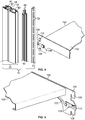
Fig. 6 shows a partial front view of a shelving system incorporating the vertical support connected to another external casing purposed as a horizontal support, and a lower perspective view of the same structure; -
Fig. 7 shows an exterior view of an embodiment of a shelving system incorporating a vertically oriented external casing engaged to a horizontally oriented external casing with an exterior connecting element, and a view of the same structure without the exterior connecting element to show an interior connecting element; -
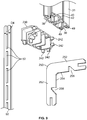
Fig. 8 shows an exploded view of an embodiment of a shelving system incorporating the vertical support with a horizontally oriented external casing with an exterior connecting element, and an interior connecting element; and -
Fig. 9 shows the components required to assemble more than one external casing together: multiple external casings (only one of multiple identical external casings shown), an exterior connecting element, an interior connecting element, and a ladder insert. - The disclosed invention includes a shelving system with at least one vertical support supporting at least one mountable attachment member having a powered appliance, which can be configured in a variety of ways to provide a shelving system that is easy to assemble, modify, and disassemble in a variety of configurations according to the practical requirements and aesthetic tastes of its user. See
Figs. 1-9 . Some embodiments include multiple vertical supports for connecting one or more attachment members, such as shelves, baskets, hangers, and posters, which contain powered appliances to allow a user to further customize the shelving system to a desired aesthetic. - The shelving system can use otherwise vertical supports that are buttressed between a floor and ceiling (or other load-bearing lower and upper surfaces); see
Fig. 1 . In some embodiments, the shelving system can employ components of the vertical supports as horizontally-oriented supports of the shelving system (Figs. 6-9 ); further embodiments can employ a variety of connecting elements to attach the vertically-oriented and horizontally-oriented components together. The external connecting elements can attach the external portions of the supports. In some embodiments, internal connecting elements can provide attachment in lieu of, or in addition to, external connecting elements. - The individual components of the shelving system display internal symmetry in at least one plane; that is, a component can be cut in half so that the two halves are mirror images of each other. The individual components can display internal symmetry in in two or more planes. The vertical supports of shelving systems have mountable attachment members with powered appliances. The vertical supports contain features that enable a user to customize a shelving system to meet her particular needs and personal tastes with minimum effort in a manner that enhances the aesthetic appeal of the shelving system while also providing power to the powered appliances in the varied configurations
- Shelving systems generally include at least one vertically-oriented element that provides structural support. Some embodiments of the invention are directed toward a vertical support (10) that promotes ease of assembly in a variety of configurations and enhances the aesthetic appeal of the vertical support and the shelving systems it can be incorporated into, as shown in
Figs. 1-5 . - The vertical support (10) includes an external casing (20) with a first end (22) and a second end (24). When in its vertical orientation, the first end (22) is also a top end (26) and the second end (24) is also a bottom end (28) of the external casing (20). The external casing (20) has a longitudinal aperture (30) that leads to a longitudinal hollow interior (38), which leads to the core (44) of the external casing (20). The longitudinal hollow interior (38) includes a space (40) for receiving a ladder insert and a space (42) for receiving a power delivery insert. The longitudinal aperture (30) is exterior to the ladder insert space (40), which is exterior to the power delivery space (42), which is exterior to the core (44). In more preferred embodiments, a vertical support (10) may have more than one longitudinal hollow interior (38) with ladder insert space (40) and power delivery insert space (42); in even more preferred embodiments, the configuration of one hollow longitudinal interior (38) with ladder insert space (40) and power delivery insert space (42) may form a mirror image of another longitudinal hollow interior (38) with ladder insert space (40) and power delivery insert space (42).
- The core (44) can be hollow at its center or can be solid.
- The edges (32) of the longitudinal aperture (30) taper inward, so that the outer edges (36) of the longitudinal aperture have a greater distance between them (D1) than the distance between the inner edges (34) of the longitudinal aperture (D2). In more preferred embodiments, the edges (32) are chamfered.
- The ladder insert (50) includes a plurality of regularly spaced perforations (52) along its length. The ladder insert (50) can be inserted into the ladder insert space (40) so that the plurality of perforations (52) provide openings that face both the longitudinal aperture (30) and the power delivery insert space (42), providing openings between the longitudinal aperture (30) and the power delivery insert space (42).
- When placed in the ladder insert space (40), the ladder insert (50) provides a structure by which a mountable attachment member (100), such as a shelf, hanger, or basket, having a powered appliance (120) can engage the vertical support (10). In some embodiments, one or more perforations (52) of the ladder insert (50) of the vertical support (10) engages the mountable attachment member (100) in a reversible manner; that is, the attachment member (100) can be removed from a perforation (52), if desired, and reengaged at a different perforation (52).
- The perforations (52) have a horizontal width (D3) that is greater than the horizontal width of the distance between the inner edges (34) of the longitudinal aperture (D2). The width (D4) of the ladder insert (50) is greater than the distance between the inner edges (34) of the longitudinal aperture (D2). This feature allows attachment elements (104) of an attachment member (100) to pass through a perforation (52) without being caught on it. For example, it would prevent the bracket (106) of a shelf (102) from being blocked from entering a perforation (52).
- The power delivery insert (60) provides power from a power source, such as electricity, to the powered appliance (120) that is attached to the attachment member (100). When placed in the power delivery insert space (42), the power delivery insert (60) has a longitudinal channel (62) that faces the ladder insert space (40). When the ladder insert (50) is simultaneously engaged within the vertical external casing (20), the power delivery insert channel (62) faces the perforations (52) of the ladder insert (50). In some embodiments, the power source may be an electrical outlet or may be supplied be other methods, such as by batteries (not shown).
- At least two interior sides (64) of the power delivery insert channel (62) have a power transmitter (66) to the powered appliance (120), such as a strip of electrically conductive material (68), for example strips comprising copper. It is preferred that the width of the power delivery insert channel (62) be greater than the horizontal width (D3) of the perforations (52) of the ladder insert (50), again so that there is no obstruction to prevent an attachment element (104) of an attachment member (100) from engaging the power delivery insert channel (62) after it passes through a perforation (52) of the ladder insert (50).
- The vertical support (10) engages power delivery insert channel (62) in a reversible manner; that is, the power delivery insert channel (62) can be inserted into and subsequently removed from the vertical support (10), if desired.
- The vertical support (10), with its ladder insert (50) and power delivery insert (60) provide a structure to support a mountable attachment member (100), via the ladder insert (50), and to provide power to a powered appliance (120) attached to the attachment member (100), via the power delivery insert (60).
- An attachment member (100) can comprise a shelf (102) with at least one attachment element (104), such as a bracket (106). See
Figs. 4-5 . In other embodiments, the attachment member (100) can comprise baskets, hangers, posters, and display monitors. The attachment element (104) can also have a power clip (108) having a power contact (110) on at least two sides (107) of the bracket (106), for providing power to a power cord (122) of the powered appliance (120). In preferred embodiments, the power contact (110) is an electrical contact that conducts electricity. - The attachment member (100) can be operatively attached to the vertical support (10) by the attachment element (104) by inserting at least one attachment element (104) through at least one perforation (52) of the ladder insert (50) and connecting the attachment element (104) to the power delivery insert channel (62) of the power delivery insert (60) so that the electrical contacts (110) of the attachment element (104) contact the power transmitter (66) on a first interior side and a second interior side (64) of the power delivery insert (60). Thus connected, power can be transmitted to the powered appliance (120).
- The attachment member (100) can be operatively attached to the vertical support (10) by the bracket (106) by inserting at least one bracket (106) through at least one perforation (52) of the ladder insert (50) and connecting the bracket (106) to the power delivery insert channel (62) of the power delivery insert (60) so that the electrical power contacts (110) of the bracket (106) contact the strips of electrically conductive material (68) on the interior sides (64) of the power delivery insert (60). Thus connected, power can be transmitted to the powered appliance (120).
- The attachment member (100) has at least two attachment elements (104) engaging the ladder insert (50). For example, a shelf (102) can have a pair of brackets (106) engaging the ladder insert (50), with a power clip (108) having electrical contacts (112) transmitting power through strips of electrically conductive material (i.e., copper) (68) of the power delivery insert (60) to the powered appliance (120) of the shelf (102).
- The invention particularly includes the following: a vertical support (10) for mounting an attachment member (100) with a powered appliance (120) onto a shelving system (210), the vertical support (10) comprising: an external casing (20) aligned vertically in use with the shelving system (210) having a longitudinal aperture (30) leading to a longitudinal hollow interior (38) comprising a space for receiving a ladder insert (40), and a space for receiving a power delivery insert (42) anterior to the ladder insert space (40); where the ladder insert has a plurality of spaced-apart perforations (52), the horizontal width of the perforations (52) being greater than the width of the longitudinal aperture (30), the ladder insert (50) engaging the ladder insert space (40) so that the plurality of perforations (52) face the longitudinal aperture (30) and the power delivery insert space (42); and where the power delivery insert (60) has a channel (62) for receiving an attachment element (104) of the attachment member (100), the horizontal width of the channel (62) being at least as wide as the horizontal width of the perforations (52) of the ladder insert (50); where a first power transmitter (66) engages an interior side (64) of the channel (62) and a second power transmitter (66) engages a different interior side (64) of the channel (62); and where the power delivery insert (60) engages the power delivery insert space (42) so that the channel (62) faces the plurality of perforations (52) of the ladder insert (50); and where the attachment member (100) includes a power clip (108), a powered appliance (120), and an attachment element (104) for engaging at least one perforation (52) of the ladder insert (50) so that the power clip (108) engages the first and second first power transmitters (66) of the channel (62) to make power available to the powered appliance (120).
- Even more further include an external casing having a first end (22), a second end (24), and a core (44), and make power available to the powered appliance (120) through a power cord (122) connecting the powered appliance (120) to the power clip (108).
- The vertical supports (10) can be assembled with the attachment members (100) to create a shelving system (210). In some embodiments, at least one vertical support can be anchored to a ceiling and floor by an anchoring mechanism (280), i.e., suction cups (282); see
Fig. 1 . Such a shelving system (210) provides display for goods or a decor unit that will support the powered appliances (120). - A shelving system (210) can be assembled from at least two vertical supports (10) and at least one horizontally-oriented external casing (220), and at least one connector (230) for engaging a vertical support (10) to a horizontally-oriented external casing (220); see
Figs.6-9 . It is preferred that the external casings (20) incorporated into the vertical supports (10) are identical to the horizontally-oriented external casings (220). - The connector (230) has at least one protrusion (242), preferably a plurality of protrusions (242), that engages corresponding interior connecting spaces (49) in the external casings (20, 220). In some embodiments, the connector can contain interior spaces that mate to corresponding protrusions in the external casings (not shown). When connected via the connector (230), the vertical support (10) and the horizontally-oriented external casing (220); it is preferred that the vertical support (10) and the horizontally-oriented external casing (220) form an angle between 60-120°, more preferred that the angle be between 75-105°, and most preferred that they form an approximate 90° (right) angle. The connector (230) hides the edges of the external casings (20, 220) and the internal portions of the vertical support (10) and the external casings (20, 220) from casual view, thus enhancing the aesthetic appeal of the assembled shelving system (210). See
Figs. 6-7 . - The connections between the vertical supports (10) and the horizontally-oriented external casings (220) can be augmented with at least one internal connection piece (250). Each internal connection piece (250) can have an L-shape with two arms (252) and each arm (252) fits into the ladder insert space (40) of an external casing (20, 220). The internal connection piece (250) connects the vertical support (10) and the horizontally-oriented external casing (220) by simultaneously engaging the ladder insert space (40) of the vertical support (10) and the ladder insert space (40) of the horizontally-oriented external casing (220).
- The internal connection piece (250) contains at least one depression (256) on the interior face (254) of each of its arms (252). See
Fig. 8 . The depressions (256) accommodate a fastener (270), such as a peg, screw, nail, or the like, the internal connection piece (250) to an external casing (20, 220). In some embodiments, the external casings (20, 220) can have at least one fastener hole (272) to guide the fastener (270) to the depression (256) of internal connection piece (250) opposite it. - Preferably at least two internal connection pieces (250) are used to augment the connection between each vertical support (10) and horizontally-oriented external casing (220).
- Preferably, the two internal connection pieces (250) have at least two dimensions of the same size as the ladder insert (50), i.e., width and depth.
- Individual components of the vertical support (10) and its individual components, such as the external casing (20), the ladder insert (50), and power delivery insert (60) can be made separately, by different methods incorporating different materials. However, it is preferred that the individual components be made such that each component have internal symmetry in at least one plane; that is, each component can be cut in half so that the two halves are mirror images of each other. The individual components can display internal symmetry in in two or more planes.
- This internal symmetry means that a component can be operatively inserted into its place in the vertical support (10) in multiple orientations. For example, a preferred embodiment of a ladder insert (50) is symmetrical along both its horizontal and vertical planes; thus it can perform the function of supporting an attachment member (100) regardless of whether it is inserted into the ladder insert space (40) "rightside-up" or "upside-down" or whether it faces "forward" or "backward." The internal symmetry of the individual components (and the spaces into which they engage the vertical support (10)) increases the ease of assembly and the number of configurations a shelving system (210) can attain.
- Similarly, the internal symmetry of the vertical support (10) enhances the ease of assembly and the number of configurations a shelving system (210) can attain, as well as enhancing the aesthetic appeal of the assembled shelving system (210). The vertical support (10) has internal symmetry in at least one plane, and even more preferably, in two or more planes.
Claims (14)
- A vertical support (10) for mounting an attachment member (100) with a powered appliance (120) onto a shelving system (210), the vertical support (10) comprising an external casing (20) aligned vertically in use with the shelving system having a longitudinal hollow interior (38) with a space (42) for receiving a power delivery insert (60);
the ladder insert (50) is placed in the ladder insert space (40) so that the plurality of perforations (52) provide openings that face both the longitudinal aperture (30) and the power delivery insert space (42) ;
and wherein the power delivery insert (60) is removable from the vertical support (10) and comprises a channel (62) for receiving an attachment element (104) of the attachment member (100) provided with a power clip (108) for providing power to the powered appliance (120), the horizontal width of the channel (62) being at least as wide as the horizontal width (D3) of the perforations (52) of the ladder insert (50);
a first power transmitter (66) on one interior side (64) of the channel (62); and a second power transmitter (66) on a different interior side (64) of the channel (62);
wherein the channel (62) faces the plurality of perforations (52) of the ladder insert (50);
and,when mounted, the attachment element (104) engages at least one perforation (52) and the first and second power transmitters (66) engage the power clip (108) of the attachment member (100), in the channel (62), to make power available to the powered appliance (120),
characterised in that
the external casing has a longitudinal aperture (30) with edges (32) that taper inward leading to the longitudinal hollow interior (38), which is provided with a further space (40) for receiving a ladder insert (50); and in that the ladder insert (50) has a plurality of spaced-apart perforations (52), the horizontal width (D3) of the perforations (52) being greater than the width (D2) of the longitudinal aperture (30). - The vertical support of Claim 1, wherein the longitudinal aperture (30) has chamfered edges.
- The vertical support of any preceding Claim, wherein:the first and second first power transmitters (66) comprise a strip of electrically conductive material (68), andthe power transmitters (66) engage power contacts (110) on at least two sides of the attachment element (104) for providing power to the powered appliance (120); andthe power that is transmitted is electrical power.
- The vertical support of Claim 3, wherein the electrically conductive material comprises copper.
- A shelving system (210) comprising at least one vertical support (10) according to any preceding Claim, with at least one attachment member (100).
- The shelving system of Claim 5, wherein the attachment member (100) comprises one of the following: a shelf, a hanger, or a media board.
- The shelving system of Claim 5 or Claim 6, wherein the attachment element (104) comprises a bracket (106).
- The shelving system of any of Claims 5 to 7, wherein the powered appliance (120) comprises one of the following: a light, a computer, a monitor, an audio system, or a credit card reader.
- The shelving system of any of Claims 5 to 8, wherein the perforations (52) comprise vertical slots and the attachment element (104) comprises downward-pointing hooks (106).
- The shelving system of any of Claims 5-9, further comprising:at least one horizontally-oriented external casing (220); andat least one connector (230) for connecting the vertical support (10) to the horizontally-orientated external casing (220).
- The shelving system of Claim 10, further comprising:
at least one internal connection piece (250) for connecting the vertical support (10) to the horizontally-oriented external casing (220), wherein the internal connecting piece (250) engages the ladder insert space (40) of the vertical support (10) and the ladder insert space (40) of the horizontally-oriented external casing (220). - The shelving system of Claim 11, comprising a fastener (270) for fastening the internal connecting piece (250) to an external casing (20, 220).
- The shelving system of Claim 11 or Claim 12, wherein the internal connection piece (250) has approximately the same depth and width as the ladder insert (50).
- The shelving system according to any of Claims 10 to 13 wherein the or each horizontally-oriented external casing (220) is of identical design to the external casing (20) of the or each vertical support (10).
Applications Claiming Priority (1)
| Application Number | Priority Date | Filing Date | Title |
|---|---|---|---|
| US15/137,825 US9831642B2 (en) | 2016-04-25 | 2016-04-25 | Vertical support for shelving system and shelving system |
Publications (2)
| Publication Number | Publication Date |
|---|---|
| EP3238567A1 EP3238567A1 (en) | 2017-11-01 |
| EP3238567B1 true EP3238567B1 (en) | 2019-07-17 |
Family
ID=58108475
Family Applications (1)
| Application Number | Title | Priority Date | Filing Date |
|---|---|---|---|
| EP17157180.5A Active EP3238567B1 (en) | 2016-04-25 | 2017-02-21 | Vertical support for shelving system and shelving system |
Country Status (4)
| Country | Link |
|---|---|
| US (1) | US9831642B2 (en) |
| EP (1) | EP3238567B1 (en) |
| CA (1) | CA2964657C (en) |
| MX (1) | MX376502B (en) |
Families Citing this family (28)
| Publication number | Priority date | Publication date | Assignee | Title |
|---|---|---|---|---|
| US9119471B2 (en) | 2013-03-14 | 2015-09-01 | Spg International Llc | Support bracket |
| CN108477854A (en) | 2013-10-01 | 2018-09-04 | Spg国际有限责任公司 | Shelf system |
| CN107524965B (en) * | 2016-06-22 | 2024-04-05 | 赛尔富电子有限公司 | Power taking system of goods shelf using LED lamp |
| DE102016124956A1 (en) * | 2016-12-20 | 2018-06-21 | Rehau Ag + Co | System for supplying a plurality of electronic display devices for displaying product-related information and goods presentation system |
| WO2018132722A1 (en) * | 2017-01-13 | 2018-07-19 | Daktronics, Inc. | Banner display |
| US10021972B1 (en) | 2017-02-17 | 2018-07-17 | Intermetro Industries Corporation | Cantilever shelving system |
| US10709237B2 (en) | 2017-02-17 | 2020-07-14 | Intermetro Industries Corporation | Cantilever shelving system |
| DE102017107379A1 (en) * | 2017-04-06 | 2018-10-11 | Grob & Hoffmann GmbH | Illuminated shelving system |
| US11122897B2 (en) * | 2017-04-07 | 2021-09-21 | RCS Syslems, Inc. | Display mounting system and method of manufacturing outriggers |
| US10492631B2 (en) * | 2017-07-13 | 2019-12-03 | Black & Decker Inc. | Wall hanging system |
| USD869882S1 (en) * | 2017-07-13 | 2019-12-17 | Modern Equipment Co., Inc. | Display shelving |
| US11253071B2 (en) * | 2017-09-15 | 2022-02-22 | Lego A/S | Shelving system |
| USD832613S1 (en) * | 2017-09-22 | 2018-11-06 | Williams-Sonoma, Inc. | Wall unit |
| US11091958B2 (en) * | 2018-01-10 | 2021-08-17 | Sub-Zero Group, Inc. | Shelf electrical signal connector |
| CN208640326U (en) * | 2018-05-14 | 2019-03-26 | 刘晓涵 | A kind of standing type supporter |
| US10939756B2 (en) * | 2018-06-22 | 2021-03-09 | Product Miniature, Inc. | Modular shelf system |
| US10646058B2 (en) * | 2018-07-09 | 2020-05-12 | Vira Insight, Llc | Retail display system with power supply interface |
| WO2020033771A1 (en) * | 2018-08-08 | 2020-02-13 | Hyperframe Inc. | Framing assembly with modular connectors |
| US10905234B1 (en) * | 2018-09-21 | 2021-02-02 | Steven Schindehette | Overhead storage system and method |
| US10646035B1 (en) * | 2018-09-21 | 2020-05-12 | Steve Schindehette | Overhead storage system and method |
| FR3082715B1 (en) * | 2019-01-15 | 2020-10-23 | France Decors | Rack console configured to receive and electrify a tablet |
| JP2020156868A (en) * | 2019-03-27 | 2020-10-01 | パナソニックIpマネジメント株式会社 | Shelf board power supply device |
| JP2020156867A (en) * | 2019-03-27 | 2020-10-01 | パナソニックIpマネジメント株式会社 | Power supply frame and power supply frame device |
| US11592879B2 (en) * | 2019-07-26 | 2023-02-28 | Artitalia Group Inc. | Modular back panel assembly for a display structure |
| IT202100013856A1 (en) * | 2021-05-27 | 2022-11-27 | Poliform S P A | UPRIGHT FOR FURNISHING ELEMENT |
| US11737586B1 (en) * | 2022-02-03 | 2023-08-29 | Imageworks Display And Marketing Group, Inc. | Merchandise display stand |
| JP2024018743A (en) * | 2022-07-29 | 2024-02-08 | 株式会社ニトリホールディングス | Tension struts and wall storage devices |
| WO2024079652A1 (en) * | 2022-10-14 | 2024-04-18 | L. & S. Italia S.P.A. | Shelf support system |
Family Cites Families (49)
| Publication number | Priority date | Publication date | Assignee | Title |
|---|---|---|---|---|
| US2441461A (en) | 1945-11-19 | 1948-05-11 | Wayne Anthony | Electric utility connection |
| US2890266A (en) * | 1955-03-01 | 1959-06-09 | Minnesota Mining & Mfg | Wire-connector |
| US3559149A (en) | 1968-10-29 | 1971-01-26 | Jack L Shagena Jr | Electrically wired baseboard |
| DE2234435C2 (en) | 1971-08-03 | 1983-04-28 | Staff GmbH & Co KG, 4920 Lemgo | Bridging adapter for power distribution bars |
| CH601930A5 (en) * | 1975-10-08 | 1978-07-14 | Fehlbaum & Co | Hollow profile shelf rail |
| US4096349A (en) | 1977-04-04 | 1978-06-20 | Lightolier Incorporated | Flexible connector for track lighting systems |
| FR2423074A1 (en) | 1978-04-14 | 1979-11-09 | Lampes Sa | CONNECTION ACCESSORIES SYSTEM FOR ASYMMETRICAL PROFILE POWER SUPPLY TRACK |
| US4243284A (en) | 1978-07-21 | 1981-01-06 | Michael Humphreys | Electrical distribution system |
| US4239932A (en) | 1979-01-18 | 1980-12-16 | Gf Business Equipment, Inc. | Partition wiring system |
| US4245874A (en) * | 1979-03-05 | 1981-01-20 | Mcgraw-Edison | Flexible connector assembly for track lighting system |
| US4312086A (en) * | 1980-02-22 | 1982-01-26 | George Nagem | Modular furniture |
| US4553809A (en) * | 1984-09-24 | 1985-11-19 | Raychem Corporation | Electrical connector |
| US4919625A (en) | 1988-04-29 | 1990-04-24 | Cooper Industries, Inc. | Track lighting apparatus |
| US4982054A (en) * | 1988-10-06 | 1991-01-01 | Raychem Corporation | Telecommunications pedestal closure with environmental control liner |
| US4973796A (en) * | 1989-08-10 | 1990-11-27 | Visu-Wall By Hbsa Industries, Inc. | Electrified wall structure |
| US5308922A (en) * | 1992-06-08 | 1994-05-03 | Reactive Industries, Inc. | Wire connector and method of manufacture |
| US5425648A (en) * | 1992-09-17 | 1995-06-20 | Farham; Howden W. | Electrical connector |
| MX9304688A (en) | 1993-01-08 | 1994-08-31 | Jacques Nadeau | ELECTRIC DISTRIBUTOR SYSTEM. |
| US5695261A (en) * | 1996-04-12 | 1997-12-09 | Slesinger; Bruce M. | Integrally powered modular furniture |
| US5921190A (en) | 1997-01-17 | 1999-07-13 | Stamford Investments, Inc. | Modular display system |
| US6033239A (en) | 1998-10-16 | 2000-03-07 | Jaakkola; Risto | Connector for track lighting systems |
| CN1310497A (en) | 2000-02-21 | 2001-08-29 | 家电宝有限公司 | Power connector for track light fixtures |
| US6244733B1 (en) | 2000-02-25 | 2001-06-12 | Juno Manufacturing, Inc. | Low voltage track lighting system |
| US6527565B1 (en) * | 2000-08-11 | 2003-03-04 | Robert L. Johns | Adjustable light display assembly |
| JP4169697B2 (en) * | 2001-12-08 | 2008-10-22 | リッタル ゲゼルシャフト ミット ベシュレンクテル ハフツング ウント コンパニー コマンディトゲゼルシャフト | Frame molding material |
| US6644988B2 (en) * | 2002-02-20 | 2003-11-11 | Rafael Healy | Fabricated baseplate for electrical installations |
| US20030224636A1 (en) * | 2002-05-29 | 2003-12-04 | Lorenzen John F. | Movable utility receptacle system |
| US6716042B2 (en) * | 2002-07-05 | 2004-04-06 | Michael Lin | Track system of projector lamp and electrical connection device assembly thereof |
| US6813896B1 (en) | 2003-07-30 | 2004-11-09 | Whirlpool Corporation | Power bus for removable refrigerator shelves |
| DE20314260U1 (en) * | 2003-09-15 | 2003-11-13 | Visplay International Ag, Muttenz | Profile rail and presentation device created with it |
| GB0408696D0 (en) | 2004-04-19 | 2004-05-19 | Daniel D | Shelving |
| US7056007B2 (en) * | 2004-05-13 | 2006-06-06 | Hwa Jung Chiu | Track lamp assembly and display with the track lamp assembly |
| US20080043456A1 (en) * | 2006-08-15 | 2008-02-21 | Bernardini Allen J | Shelf light bracket connector system |
| DE102007028395A1 (en) | 2007-06-15 | 2008-12-18 | Brinkmann, Wolfgang | Floor support system |
| US20090152944A1 (en) * | 2007-07-26 | 2009-06-18 | Rubbermaid, Inc. | Power system |
| US8172589B2 (en) * | 2007-08-09 | 2012-05-08 | Haworth, Inc. | Modular electrical distribution system for a building |
| DE102008010205A1 (en) | 2008-02-20 | 2009-08-27 | Konrad Knoblauch Vermögensverwaltung GmbH | rail |
| US7654834B1 (en) | 2008-05-05 | 2010-02-02 | Genlyte Thomas Group, Llc | Track lighting assembly |
| US20110140686A1 (en) * | 2009-12-16 | 2011-06-16 | Lineage Power Corporation | Thermal extension structures for monitoring bus bar terminations |
| WO2011150309A2 (en) | 2010-05-28 | 2011-12-01 | Steelcase Inc. | Office workwall system |
| US9204736B2 (en) * | 2012-08-22 | 2015-12-08 | Streater LLC | Shelving unit lighting system |
| DE202012008355U1 (en) * | 2012-09-03 | 2012-10-24 | Visplay International Ag | Suspension device for the presentation of goods with a current-carrying profile rail and therein suspendable primary carrier |
| US8967740B2 (en) | 2013-02-07 | 2015-03-03 | Whirlpool Corporation | Electrical connector for adjustable refrigerator shelf |
| US9098823B2 (en) * | 2013-02-12 | 2015-08-04 | Powerwall, Inc. | Shelf power system |
| KR20240127447A (en) | 2013-06-20 | 2024-08-22 | 젬트론 코포레이션 | Modular luminaires for appliance lighting |
| CN203466400U (en) | 2013-08-29 | 2014-03-05 | 东莞恒隆家具制造有限公司 | A light-emitting system electrification device for display industry |
| DE102013114289B4 (en) | 2013-12-18 | 2023-09-07 | Juvema Ag | Shelving system with electrical supply |
| US9680270B2 (en) * | 2014-05-15 | 2017-06-13 | Elmer A. Wessel | Apparatus for enhanced merchandise display |
| US9537274B1 (en) * | 2016-02-16 | 2017-01-03 | Elemental LED, Inc. | Modular power and connector system for lighting elements |
-
2016
- 2016-04-25 US US15/137,825 patent/US9831642B2/en active Active
-
2017
- 2017-02-21 EP EP17157180.5A patent/EP3238567B1/en active Active
- 2017-04-19 CA CA2964657A patent/CA2964657C/en active Active
- 2017-04-24 MX MX2017005317A patent/MX376502B/en active IP Right Grant
Non-Patent Citations (1)
| Title |
|---|
| None * |
Also Published As
| Publication number | Publication date |
|---|---|
| CA2964657C (en) | 2023-10-03 |
| US9831642B2 (en) | 2017-11-28 |
| US20170310090A1 (en) | 2017-10-26 |
| MX376502B (en) | 2025-03-07 |
| CA2964657A1 (en) | 2017-10-25 |
| EP3238567A1 (en) | 2017-11-01 |
| MX2017005317A (en) | 2018-08-20 |
Similar Documents
| Publication | Publication Date | Title |
|---|---|---|
| CA2964657C (en) | Vertical support for shelving system and shelving system | |
| US8984781B2 (en) | Configurable large-depth panel display | |
| US20130299439A1 (en) | Powering Assembly and Method For Adjustable Shelving | |
| US5509541A (en) | Bracket construction | |
| US6199705B1 (en) | Lighting fixture display | |
| TWI396960B (en) | Backstop module | |
| EP1884177A1 (en) | A shelf for a shelving unit | |
| ES2691714T3 (en) | Presentation installation, in particular for products | |
| US10729237B2 (en) | Configurable and dismantlable display case system comprising a plastic shelving unit with trays at different levels, and method of assembly | |
| MX2012013452A (en) | Wall-storage mounting system. | |
| US20200008591A1 (en) | Retail Display System with Power Supply Interface | |
| US7600895B2 (en) | Light display unit with fixture and light strand | |
| US9307669B1 (en) | Adjustable shelving mount with cord organizer | |
| US10568444B2 (en) | Piece of furniture having at least one support rod | |
| US6405879B1 (en) | Vertical card display | |
| US11122897B2 (en) | Display mounting system and method of manufacturing outriggers | |
| US6767234B1 (en) | Hook and hang display system with plug-in bullnose header module | |
| WO2014118528A1 (en) | Display panel and method of manufacture | |
| JP5808179B2 (en) | System back guard and kitchen | |
| JP2009002100A (en) | Continuous panel wall structure | |
| GB2293307A (en) | Support column for shelving | |
| TW201319784A (en) | Back rack module | |
| AU2007262668B2 (en) | A shelving system | |
| KR20180067099A (en) | Goods Shelves | |
| KR101699759B1 (en) | Display stand for arranging merchandise thereon |
Legal Events
| Date | Code | Title | Description |
|---|---|---|---|
| PUAI | Public reference made under article 153(3) epc to a published international application that has entered the european phase |
Free format text: ORIGINAL CODE: 0009012 |
|
| STAA | Information on the status of an ep patent application or granted ep patent |
Free format text: STATUS: THE APPLICATION HAS BEEN PUBLISHED |
|
| AK | Designated contracting states |
Kind code of ref document: A1 Designated state(s): AL AT BE BG CH CY CZ DE DK EE ES FI FR GB GR HR HU IE IS IT LI LT LU LV MC MK MT NL NO PL PT RO RS SE SI SK SM TR |
|
| AX | Request for extension of the european patent |
Extension state: BA ME |
|
| STAA | Information on the status of an ep patent application or granted ep patent |
Free format text: STATUS: REQUEST FOR EXAMINATION WAS MADE |
|
| 17P | Request for examination filed |
Effective date: 20180105 |
|
| RBV | Designated contracting states (corrected) |
Designated state(s): AL AT BE BG CH CY CZ DE DK EE ES FI FR GB GR HR HU IE IS IT LI LT LU LV MC MK MT NL NO PL PT RO RS SE SI SK SM TR |
|
| STAA | Information on the status of an ep patent application or granted ep patent |
Free format text: STATUS: EXAMINATION IS IN PROGRESS |
|
| 17Q | First examination report despatched |
Effective date: 20180703 |
|
| RIN1 | Information on inventor provided before grant (corrected) |
Inventor name: WELLS, NATHAN Inventor name: WOOD, GRAHAM Inventor name: WOODLEY, BRETT Inventor name: HALLER, ERICH |
|
| GRAP | Despatch of communication of intention to grant a patent |
Free format text: ORIGINAL CODE: EPIDOSNIGR1 |
|
| STAA | Information on the status of an ep patent application or granted ep patent |
Free format text: STATUS: GRANT OF PATENT IS INTENDED |
|
| INTG | Intention to grant announced |
Effective date: 20181120 |
|
| GRAJ | Information related to disapproval of communication of intention to grant by the applicant or resumption of examination proceedings by the epo deleted |
Free format text: ORIGINAL CODE: EPIDOSDIGR1 |
|
| STAA | Information on the status of an ep patent application or granted ep patent |
Free format text: STATUS: EXAMINATION IS IN PROGRESS |
|
| INTC | Intention to grant announced (deleted) | ||
| GRAP | Despatch of communication of intention to grant a patent |
Free format text: ORIGINAL CODE: EPIDOSNIGR1 |
|
| STAA | Information on the status of an ep patent application or granted ep patent |
Free format text: STATUS: GRANT OF PATENT IS INTENDED |
|
| INTG | Intention to grant announced |
Effective date: 20190430 |
|
| GRAA | (expected) grant |
Free format text: ORIGINAL CODE: 0009210 |
|
| STAA | Information on the status of an ep patent application or granted ep patent |
Free format text: STATUS: THE PATENT HAS BEEN GRANTED |
|
| AK | Designated contracting states |
Kind code of ref document: B1 Designated state(s): AL AT BE BG CH CY CZ DE DK EE ES FI FR GB GR HR HU IE IS IT LI LT LU LV MC MK MT NL NO PL PT RO RS SE SI SK SM TR |
|
| REG | Reference to a national code |
Ref country code: GB Ref legal event code: FG4D |
|
| REG | Reference to a national code |
Ref country code: CH Ref legal event code: EP |
|
| REG | Reference to a national code |
Ref country code: DE Ref legal event code: R096 Ref document number: 602017005255 Country of ref document: DE |
|
| REG | Reference to a national code |
Ref country code: IE Ref legal event code: FG4D |
|
| REG | Reference to a national code |
Ref country code: AT Ref legal event code: REF Ref document number: 1155023 Country of ref document: AT Kind code of ref document: T Effective date: 20190815 |
|
| REG | Reference to a national code |
Ref country code: NL Ref legal event code: MP Effective date: 20190717 |
|
| REG | Reference to a national code |
Ref country code: LT Ref legal event code: MG4D |
|
| REG | Reference to a national code |
Ref country code: AT Ref legal event code: MK05 Ref document number: 1155023 Country of ref document: AT Kind code of ref document: T Effective date: 20190717 |
|
| PG25 | Lapsed in a contracting state [announced via postgrant information from national office to epo] |
Ref country code: FI Free format text: LAPSE BECAUSE OF FAILURE TO SUBMIT A TRANSLATION OF THE DESCRIPTION OR TO PAY THE FEE WITHIN THE PRESCRIBED TIME-LIMIT Effective date: 20190717 Ref country code: BG Free format text: LAPSE BECAUSE OF FAILURE TO SUBMIT A TRANSLATION OF THE DESCRIPTION OR TO PAY THE FEE WITHIN THE PRESCRIBED TIME-LIMIT Effective date: 20191017 Ref country code: SE Free format text: LAPSE BECAUSE OF FAILURE TO SUBMIT A TRANSLATION OF THE DESCRIPTION OR TO PAY THE FEE WITHIN THE PRESCRIBED TIME-LIMIT Effective date: 20190717 Ref country code: AT Free format text: LAPSE BECAUSE OF FAILURE TO SUBMIT A TRANSLATION OF THE DESCRIPTION OR TO PAY THE FEE WITHIN THE PRESCRIBED TIME-LIMIT Effective date: 20190717 Ref country code: HR Free format text: LAPSE BECAUSE OF FAILURE TO SUBMIT A TRANSLATION OF THE DESCRIPTION OR TO PAY THE FEE WITHIN THE PRESCRIBED TIME-LIMIT Effective date: 20190717 Ref country code: NO Free format text: LAPSE BECAUSE OF FAILURE TO SUBMIT A TRANSLATION OF THE DESCRIPTION OR TO PAY THE FEE WITHIN THE PRESCRIBED TIME-LIMIT Effective date: 20191017 Ref country code: LT Free format text: LAPSE BECAUSE OF FAILURE TO SUBMIT A TRANSLATION OF THE DESCRIPTION OR TO PAY THE FEE WITHIN THE PRESCRIBED TIME-LIMIT Effective date: 20190717 Ref country code: PT Free format text: LAPSE BECAUSE OF FAILURE TO SUBMIT A TRANSLATION OF THE DESCRIPTION OR TO PAY THE FEE WITHIN THE PRESCRIBED TIME-LIMIT Effective date: 20191118 Ref country code: NL Free format text: LAPSE BECAUSE OF FAILURE TO SUBMIT A TRANSLATION OF THE DESCRIPTION OR TO PAY THE FEE WITHIN THE PRESCRIBED TIME-LIMIT Effective date: 20190717 |
|
| PG25 | Lapsed in a contracting state [announced via postgrant information from national office to epo] |
Ref country code: GR Free format text: LAPSE BECAUSE OF FAILURE TO SUBMIT A TRANSLATION OF THE DESCRIPTION OR TO PAY THE FEE WITHIN THE PRESCRIBED TIME-LIMIT Effective date: 20191018 Ref country code: LV Free format text: LAPSE BECAUSE OF FAILURE TO SUBMIT A TRANSLATION OF THE DESCRIPTION OR TO PAY THE FEE WITHIN THE PRESCRIBED TIME-LIMIT Effective date: 20190717 Ref country code: AL Free format text: LAPSE BECAUSE OF FAILURE TO SUBMIT A TRANSLATION OF THE DESCRIPTION OR TO PAY THE FEE WITHIN THE PRESCRIBED TIME-LIMIT Effective date: 20190717 Ref country code: ES Free format text: LAPSE BECAUSE OF FAILURE TO SUBMIT A TRANSLATION OF THE DESCRIPTION OR TO PAY THE FEE WITHIN THE PRESCRIBED TIME-LIMIT Effective date: 20190717 Ref country code: RS Free format text: LAPSE BECAUSE OF FAILURE TO SUBMIT A TRANSLATION OF THE DESCRIPTION OR TO PAY THE FEE WITHIN THE PRESCRIBED TIME-LIMIT Effective date: 20190717 Ref country code: IS Free format text: LAPSE BECAUSE OF FAILURE TO SUBMIT A TRANSLATION OF THE DESCRIPTION OR TO PAY THE FEE WITHIN THE PRESCRIBED TIME-LIMIT Effective date: 20191117 |
|
| PG25 | Lapsed in a contracting state [announced via postgrant information from national office to epo] |
Ref country code: TR Free format text: LAPSE BECAUSE OF FAILURE TO SUBMIT A TRANSLATION OF THE DESCRIPTION OR TO PAY THE FEE WITHIN THE PRESCRIBED TIME-LIMIT Effective date: 20190717 |
|
| PG25 | Lapsed in a contracting state [announced via postgrant information from national office to epo] |
Ref country code: RO Free format text: LAPSE BECAUSE OF FAILURE TO SUBMIT A TRANSLATION OF THE DESCRIPTION OR TO PAY THE FEE WITHIN THE PRESCRIBED TIME-LIMIT Effective date: 20190717 Ref country code: PL Free format text: LAPSE BECAUSE OF FAILURE TO SUBMIT A TRANSLATION OF THE DESCRIPTION OR TO PAY THE FEE WITHIN THE PRESCRIBED TIME-LIMIT Effective date: 20190717 Ref country code: EE Free format text: LAPSE BECAUSE OF FAILURE TO SUBMIT A TRANSLATION OF THE DESCRIPTION OR TO PAY THE FEE WITHIN THE PRESCRIBED TIME-LIMIT Effective date: 20190717 Ref country code: IT Free format text: LAPSE BECAUSE OF FAILURE TO SUBMIT A TRANSLATION OF THE DESCRIPTION OR TO PAY THE FEE WITHIN THE PRESCRIBED TIME-LIMIT Effective date: 20190717 Ref country code: DK Free format text: LAPSE BECAUSE OF FAILURE TO SUBMIT A TRANSLATION OF THE DESCRIPTION OR TO PAY THE FEE WITHIN THE PRESCRIBED TIME-LIMIT Effective date: 20190717 |
|
| PG25 | Lapsed in a contracting state [announced via postgrant information from national office to epo] |
Ref country code: SK Free format text: LAPSE BECAUSE OF FAILURE TO SUBMIT A TRANSLATION OF THE DESCRIPTION OR TO PAY THE FEE WITHIN THE PRESCRIBED TIME-LIMIT Effective date: 20190717 Ref country code: CZ Free format text: LAPSE BECAUSE OF FAILURE TO SUBMIT A TRANSLATION OF THE DESCRIPTION OR TO PAY THE FEE WITHIN THE PRESCRIBED TIME-LIMIT Effective date: 20190717 Ref country code: SM Free format text: LAPSE BECAUSE OF FAILURE TO SUBMIT A TRANSLATION OF THE DESCRIPTION OR TO PAY THE FEE WITHIN THE PRESCRIBED TIME-LIMIT Effective date: 20190717 Ref country code: IS Free format text: LAPSE BECAUSE OF FAILURE TO SUBMIT A TRANSLATION OF THE DESCRIPTION OR TO PAY THE FEE WITHIN THE PRESCRIBED TIME-LIMIT Effective date: 20200224 |
|
| REG | Reference to a national code |
Ref country code: DE Ref legal event code: R097 Ref document number: 602017005255 Country of ref document: DE |
|
| PLBE | No opposition filed within time limit |
Free format text: ORIGINAL CODE: 0009261 |
|
| STAA | Information on the status of an ep patent application or granted ep patent |
Free format text: STATUS: NO OPPOSITION FILED WITHIN TIME LIMIT |
|
| PG2D | Information on lapse in contracting state deleted |
Ref country code: IS |
|
| 26N | No opposition filed |
Effective date: 20200603 |
|
| PG25 | Lapsed in a contracting state [announced via postgrant information from national office to epo] |
Ref country code: SI Free format text: LAPSE BECAUSE OF FAILURE TO SUBMIT A TRANSLATION OF THE DESCRIPTION OR TO PAY THE FEE WITHIN THE PRESCRIBED TIME-LIMIT Effective date: 20190717 |
|
| REG | Reference to a national code |
Ref country code: DE Ref legal event code: R119 Ref document number: 602017005255 Country of ref document: DE |
|
| REG | Reference to a national code |
Ref country code: CH Ref legal event code: PL |
|
| REG | Reference to a national code |
Ref country code: BE Ref legal event code: MM Effective date: 20200229 |
|
| PG25 | Lapsed in a contracting state [announced via postgrant information from national office to epo] |
Ref country code: LU Free format text: LAPSE BECAUSE OF NON-PAYMENT OF DUE FEES Effective date: 20200221 Ref country code: MC Free format text: LAPSE BECAUSE OF FAILURE TO SUBMIT A TRANSLATION OF THE DESCRIPTION OR TO PAY THE FEE WITHIN THE PRESCRIBED TIME-LIMIT Effective date: 20190717 |
|
| PG25 | Lapsed in a contracting state [announced via postgrant information from national office to epo] |
Ref country code: CH Free format text: LAPSE BECAUSE OF NON-PAYMENT OF DUE FEES Effective date: 20200229 Ref country code: LI Free format text: LAPSE BECAUSE OF NON-PAYMENT OF DUE FEES Effective date: 20200229 |
|
| PG25 | Lapsed in a contracting state [announced via postgrant information from national office to epo] |
Ref country code: FR Free format text: LAPSE BECAUSE OF NON-PAYMENT OF DUE FEES Effective date: 20200229 Ref country code: DE Free format text: LAPSE BECAUSE OF NON-PAYMENT OF DUE FEES Effective date: 20200901 Ref country code: IE Free format text: LAPSE BECAUSE OF NON-PAYMENT OF DUE FEES Effective date: 20200221 |
|
| PG25 | Lapsed in a contracting state [announced via postgrant information from national office to epo] |
Ref country code: BE Free format text: LAPSE BECAUSE OF NON-PAYMENT OF DUE FEES Effective date: 20200229 |
|
| GBPC | Gb: european patent ceased through non-payment of renewal fee |
Effective date: 20210221 |
|
| PG25 | Lapsed in a contracting state [announced via postgrant information from national office to epo] |
Ref country code: GB Free format text: LAPSE BECAUSE OF NON-PAYMENT OF DUE FEES Effective date: 20210221 |
|
| PG25 | Lapsed in a contracting state [announced via postgrant information from national office to epo] |
Ref country code: MT Free format text: LAPSE BECAUSE OF FAILURE TO SUBMIT A TRANSLATION OF THE DESCRIPTION OR TO PAY THE FEE WITHIN THE PRESCRIBED TIME-LIMIT Effective date: 20190717 Ref country code: CY Free format text: LAPSE BECAUSE OF FAILURE TO SUBMIT A TRANSLATION OF THE DESCRIPTION OR TO PAY THE FEE WITHIN THE PRESCRIBED TIME-LIMIT Effective date: 20190717 |
|
| PG25 | Lapsed in a contracting state [announced via postgrant information from national office to epo] |
Ref country code: MK Free format text: LAPSE BECAUSE OF FAILURE TO SUBMIT A TRANSLATION OF THE DESCRIPTION OR TO PAY THE FEE WITHIN THE PRESCRIBED TIME-LIMIT Effective date: 20190717 |