EP3237344B1 - Energy-efficient process and installation for melting vitrifiable material in a flame fired furnace - Google Patents
Energy-efficient process and installation for melting vitrifiable material in a flame fired furnace Download PDFInfo
- Publication number
- EP3237344B1 EP3237344B1 EP15830980.7A EP15830980A EP3237344B1 EP 3237344 B1 EP3237344 B1 EP 3237344B1 EP 15830980 A EP15830980 A EP 15830980A EP 3237344 B1 EP3237344 B1 EP 3237344B1
- Authority
- EP
- European Patent Office
- Prior art keywords
- heat transfer
- reactant
- transfer fluid
- inlet
- heat
- Prior art date
- Legal status (The legal status is an assumption and is not a legal conclusion. Google has not performed a legal analysis and makes no representation as to the accuracy of the status listed.)
- Not-in-force
Links
- 238000002844 melting Methods 0.000 title claims description 33
- 238000000034 method Methods 0.000 title claims description 32
- 238000009434 installation Methods 0.000 title claims description 24
- 239000000463 material Substances 0.000 title claims description 16
- 230000008018 melting Effects 0.000 title claims description 16
- 239000012530 fluid Substances 0.000 claims description 103
- 239000013529 heat transfer fluid Substances 0.000 claims description 99
- 239000000446 fuel Substances 0.000 claims description 91
- 239000000376 reactant Substances 0.000 claims description 77
- 239000007800 oxidant agent Substances 0.000 claims description 74
- 230000001590 oxidative effect Effects 0.000 claims description 74
- QVGXLLKOCUKJST-UHFFFAOYSA-N atomic oxygen Chemical compound [O] QVGXLLKOCUKJST-UHFFFAOYSA-N 0.000 claims description 66
- 239000001301 oxygen Substances 0.000 claims description 66
- 229910052760 oxygen Inorganic materials 0.000 claims description 66
- UGFAIRIUMAVXCW-UHFFFAOYSA-N Carbon monoxide Chemical compound [O+]#[C-] UGFAIRIUMAVXCW-UHFFFAOYSA-N 0.000 claims description 47
- 239000003546 flue gas Substances 0.000 claims description 45
- 238000002485 combustion reaction Methods 0.000 claims description 30
- 230000005611 electricity Effects 0.000 claims description 19
- 238000010438 heat treatment Methods 0.000 claims description 17
- 239000011521 glass Substances 0.000 claims description 9
- 239000003570 air Substances 0.000 description 24
- 239000007788 liquid Substances 0.000 description 20
- 239000007789 gas Substances 0.000 description 17
- 238000004519 manufacturing process Methods 0.000 description 13
- VNWKTOKETHGBQD-UHFFFAOYSA-N methane Chemical compound C VNWKTOKETHGBQD-UHFFFAOYSA-N 0.000 description 12
- 239000004449 solid propellant Substances 0.000 description 12
- 238000000889 atomisation Methods 0.000 description 7
- 239000003345 natural gas Substances 0.000 description 6
- 239000002918 waste heat Substances 0.000 description 5
- 238000011084 recovery Methods 0.000 description 4
- YXFVVABEGXRONW-UHFFFAOYSA-N Toluene Chemical compound CC1=CC=CC=C1 YXFVVABEGXRONW-UHFFFAOYSA-N 0.000 description 3
- 239000003517 fume Substances 0.000 description 3
- 238000002156 mixing Methods 0.000 description 3
- 239000000203 mixture Substances 0.000 description 3
- 239000006060 molten glass Substances 0.000 description 3
- 239000007921 spray Substances 0.000 description 3
- XLYOFNOQVPJJNP-UHFFFAOYSA-N water Substances O XLYOFNOQVPJJNP-UHFFFAOYSA-N 0.000 description 3
- OFBQJSOFQDEBGM-UHFFFAOYSA-N Pentane Chemical compound CCCCC OFBQJSOFQDEBGM-UHFFFAOYSA-N 0.000 description 2
- 229910000831 Steel Inorganic materials 0.000 description 2
- 239000004568 cement Substances 0.000 description 2
- 239000005356 container glass Substances 0.000 description 2
- 238000005336 cracking Methods 0.000 description 2
- 239000005357 flat glass Substances 0.000 description 2
- 239000000156 glass melt Substances 0.000 description 2
- 238000000926 separation method Methods 0.000 description 2
- 239000007787 solid Substances 0.000 description 2
- 239000010959 steel Substances 0.000 description 2
- RYGMFSIKBFXOCR-UHFFFAOYSA-N Copper Chemical compound [Cu] RYGMFSIKBFXOCR-UHFFFAOYSA-N 0.000 description 1
- MYMOFIZGZYHOMD-UHFFFAOYSA-N Dioxygen Chemical compound O=O MYMOFIZGZYHOMD-UHFFFAOYSA-N 0.000 description 1
- PMZURENOXWZQFD-UHFFFAOYSA-L Sodium Sulfate Chemical compound [Na+].[Na+].[O-]S([O-])(=O)=O PMZURENOXWZQFD-UHFFFAOYSA-L 0.000 description 1
- 230000032683 aging Effects 0.000 description 1
- 239000004411 aluminium Substances 0.000 description 1
- XAGFODPZIPBFFR-UHFFFAOYSA-N aluminium Chemical compound [Al] XAGFODPZIPBFFR-UHFFFAOYSA-N 0.000 description 1
- 229910052782 aluminium Inorganic materials 0.000 description 1
- 239000012080 ambient air Substances 0.000 description 1
- 150000001642 boronic acid derivatives Chemical class 0.000 description 1
- 230000015556 catabolic process Effects 0.000 description 1
- 239000011335 coal coke Substances 0.000 description 1
- 239000003034 coal gas Substances 0.000 description 1
- 238000001816 cooling Methods 0.000 description 1
- 239000010949 copper Substances 0.000 description 1
- 229910052802 copper Inorganic materials 0.000 description 1
- 238000005260 corrosion Methods 0.000 description 1
- 230000007797 corrosion Effects 0.000 description 1
- 238000006731 degradation reaction Methods 0.000 description 1
- 230000002542 deteriorative effect Effects 0.000 description 1
- 238000010790 dilution Methods 0.000 description 1
- 239000012895 dilution Substances 0.000 description 1
- 239000010771 distillate fuel oil Substances 0.000 description 1
- 230000003628 erosive effect Effects 0.000 description 1
- 239000000284 extract Substances 0.000 description 1
- 150000002222 fluorine compounds Chemical class 0.000 description 1
- 239000000295 fuel oil Substances 0.000 description 1
- 238000005816 glass manufacturing process Methods 0.000 description 1
- 239000010763 heavy fuel oil Substances 0.000 description 1
- 239000000155 melt Substances 0.000 description 1
- 238000010309 melting process Methods 0.000 description 1
- 239000003921 oil Substances 0.000 description 1
- 239000002006 petroleum coke Substances 0.000 description 1
- 238000010248 power generation Methods 0.000 description 1
- 239000002002 slurry Substances 0.000 description 1
- 239000005361 soda-lime glass Substances 0.000 description 1
- 235000013024 sodium fluoride Nutrition 0.000 description 1
- 229910052938 sodium sulfate Inorganic materials 0.000 description 1
- 235000011152 sodium sulphate Nutrition 0.000 description 1
- 235000010339 sodium tetraborate Nutrition 0.000 description 1
- 239000000126 substance Substances 0.000 description 1
- 238000011144 upstream manufacturing Methods 0.000 description 1
- 239000002023 wood Substances 0.000 description 1
Images
Classifications
-
- C—CHEMISTRY; METALLURGY
- C03—GLASS; MINERAL OR SLAG WOOL
- C03B—MANUFACTURE, SHAPING, OR SUPPLEMENTARY PROCESSES
- C03B5/00—Melting in furnaces; Furnaces so far as specially adapted for glass manufacture
- C03B5/16—Special features of the melting process; Auxiliary means specially adapted for glass-melting furnaces
- C03B5/235—Heating the glass
- C03B5/2353—Heating the glass by combustion with pure oxygen or oxygen-enriched air, e.g. using oxy-fuel burners or oxygen lances
-
- C—CHEMISTRY; METALLURGY
- C03—GLASS; MINERAL OR SLAG WOOL
- C03B—MANUFACTURE, SHAPING, OR SUPPLEMENTARY PROCESSES
- C03B5/00—Melting in furnaces; Furnaces so far as specially adapted for glass manufacture
- C03B5/16—Special features of the melting process; Auxiliary means specially adapted for glass-melting furnaces
- C03B5/235—Heating the glass
- C03B5/237—Regenerators or recuperators specially adapted for glass-melting furnaces
-
- F—MECHANICAL ENGINEERING; LIGHTING; HEATING; WEAPONS; BLASTING
- F23—COMBUSTION APPARATUS; COMBUSTION PROCESSES
- F23L—SUPPLYING AIR OR NON-COMBUSTIBLE LIQUIDS OR GASES TO COMBUSTION APPARATUS IN GENERAL ; VALVES OR DAMPERS SPECIALLY ADAPTED FOR CONTROLLING AIR SUPPLY OR DRAUGHT IN COMBUSTION APPARATUS; INDUCING DRAUGHT IN COMBUSTION APPARATUS; TOPS FOR CHIMNEYS OR VENTILATING SHAFTS; TERMINALS FOR FLUES
- F23L15/00—Heating of air supplied for combustion
- F23L15/04—Arrangements of recuperators
-
- F—MECHANICAL ENGINEERING; LIGHTING; HEATING; WEAPONS; BLASTING
- F23—COMBUSTION APPARATUS; COMBUSTION PROCESSES
- F23L—SUPPLYING AIR OR NON-COMBUSTIBLE LIQUIDS OR GASES TO COMBUSTION APPARATUS IN GENERAL ; VALVES OR DAMPERS SPECIALLY ADAPTED FOR CONTROLLING AIR SUPPLY OR DRAUGHT IN COMBUSTION APPARATUS; INDUCING DRAUGHT IN COMBUSTION APPARATUS; TOPS FOR CHIMNEYS OR VENTILATING SHAFTS; TERMINALS FOR FLUES
- F23L7/00—Supplying non-combustible liquids or gases, other than air, to the fire, e.g. oxygen, steam
- F23L7/007—Supplying oxygen or oxygen-enriched air
-
- F—MECHANICAL ENGINEERING; LIGHTING; HEATING; WEAPONS; BLASTING
- F28—HEAT EXCHANGE IN GENERAL
- F28D—HEAT-EXCHANGE APPARATUS, NOT PROVIDED FOR IN ANOTHER SUBCLASS, IN WHICH THE HEAT-EXCHANGE MEDIA DO NOT COME INTO DIRECT CONTACT
- F28D21/00—Heat-exchange apparatus not covered by any of the groups F28D1/00 - F28D20/00
- F28D2021/0019—Other heat exchangers for particular applications; Heat exchange systems not otherwise provided for
- F28D2021/0056—Other heat exchangers for particular applications; Heat exchange systems not otherwise provided for for ovens or furnaces
- F28D2021/0057—Other heat exchangers for particular applications; Heat exchange systems not otherwise provided for for ovens or furnaces for melting materials
-
- Y—GENERAL TAGGING OF NEW TECHNOLOGICAL DEVELOPMENTS; GENERAL TAGGING OF CROSS-SECTIONAL TECHNOLOGIES SPANNING OVER SEVERAL SECTIONS OF THE IPC; TECHNICAL SUBJECTS COVERED BY FORMER USPC CROSS-REFERENCE ART COLLECTIONS [XRACs] AND DIGESTS
- Y02—TECHNOLOGIES OR APPLICATIONS FOR MITIGATION OR ADAPTATION AGAINST CLIMATE CHANGE
- Y02E—REDUCTION OF GREENHOUSE GAS [GHG] EMISSIONS, RELATED TO ENERGY GENERATION, TRANSMISSION OR DISTRIBUTION
- Y02E20/00—Combustion technologies with mitigation potential
- Y02E20/34—Indirect CO2mitigation, i.e. by acting on non CO2directly related matters of the process, e.g. pre-heating or heat recovery
-
- Y—GENERAL TAGGING OF NEW TECHNOLOGICAL DEVELOPMENTS; GENERAL TAGGING OF CROSS-SECTIONAL TECHNOLOGIES SPANNING OVER SEVERAL SECTIONS OF THE IPC; TECHNICAL SUBJECTS COVERED BY FORMER USPC CROSS-REFERENCE ART COLLECTIONS [XRACs] AND DIGESTS
- Y02—TECHNOLOGIES OR APPLICATIONS FOR MITIGATION OR ADAPTATION AGAINST CLIMATE CHANGE
- Y02P—CLIMATE CHANGE MITIGATION TECHNOLOGIES IN THE PRODUCTION OR PROCESSING OF GOODS
- Y02P40/00—Technologies relating to the processing of minerals
- Y02P40/50—Glass production, e.g. reusing waste heat during processing or shaping
Definitions
- the present invention relates to processes and installations for melting vitrifiable material in a flame-fired furnace, such as, in particular, a glass-melting furnace whereby heat evacuated from the furnace together with the combustion flue gas is used for heating the furnace.
- a flame-fired furnace such as, in particular, a glass-melting furnace whereby heat evacuated from the furnace together with the combustion flue gas is used for heating the furnace.
- flame-fired furnaces for melting vitrifiable material are operated with air as the combustion oxidant, whereby said air may be preheated upstream of the furnace by heat exchange with hot flue gas from the furnace in a regenerator or recuperator.
- the temperature of the oxygen-rich oxidant can be from 300°C to 650°C.
- thermal energy is not transferred directly from the hot flue gas to the oxidant, as is the case in combustion air recuperators, but is instead transferred from the hot flue gas to the oxygen-rich combustion oxidant via an intermediate heat transfer fluid, such as air, thereby ensuring that no direct contact can take place between the hot flue gas and the highly reactive oxygen-rich oxidant, even in the case of possible erosion or corrosion of the heat exchange equipment in contact with the particle-laden flue gas and corrosive (hot) oxygen-rich oxidant.
- an intermediate heat transfer fluid such as air
- the amount of residual heat from the flue gas which can thus be reutilized in the furnace is limited by the temperature to which the oxygen-rich oxidant can safely be preheated and, when the fuel is also preheated in the heat-recovery process, by the temperature to which the fuel can safely be preheated without deteriorating (e.g. by cracking)
- An intermediate fluid such as thermal oil, air or pressurized water, may be employed to transfer recoverable heat from the heat source to the working fluid of the alternative Rankine cycle.
- the heat source can be a liquid or gas stream produced either as flue gas as a direct result of oxygen-enhanced combustion or as any stream utilized for cooling within the industrial process itself in order to meet the process needs.
- the temperature of the heat source is below 600°C, preferably between 400°C and 100°C.
- the examples relate to cement plants generating kiln exhaust gases with a temperature of 332°C and clinker cooler exhaust gases with a temperature of respectively 403°C and 440°C, as well as to a steel reheat furnace generating a waste heat stream at a temperature of 482°C.
- the above method is clearly not suited for efficient power generation from the flue gas of a glass-melting furnace which, as indicated above, leaves the furnace at temperatures well above 1000°C.
- oxygen-rich oxidant refers to an oxidant having an oxygen content higher than that of air, preferably containing from 50%vol to 100%vol oxygen.
- heat exchange between two fluids refers to the transfer of heat from one fluid (the heat-source fluid) to a second fluid (the fluid to be heated) without any direct contact or mixing between the two fluids.
- heat exchanger refers to a heating installation or a heating device in which a heat-source fluid, which introduces heat into the heat exchanger, and a fluid to be heated circulate in distinct enclosures or circuits, i.e. without any direct contact or mixing between said fluids, and in which heat is transferred from the heat-source fluid to the fluid to be heated across one or more walls separating the distinct disclosures or circuits.
- two elements are "in fluid connection" with one another when they are connected so as to enable a fluid to flow from one of the elements to the other, typically by one or more fluid transport conduits.
- condensibles refers to substances present in the furnace flue gas which liquefy or solidify at temperatures in the range from 300°C to 1000°C, in particular in the range of 300°C to 880°C, at pressures in the range of 900 mbar to 1100 mbar.
- Sodium sulfate, borates and fluorides are examples of such condensibles which may be present in flue gas from a glass-melting furnace.
- heating refers to the heating of a vitrifiable material or of a combustion reactant before it is introduced into a furnace.
- the heat present in the flue gas evacuated from the furnace is called “residual heat" by the person skilled in the art because said heat has been evacuated from the furnace without having been absorbed by the vitrificable material.
- Rankine cycle can refer both to the Rankine cycle process and to a Rankine cycle unit for performing a Rankine cycle process.
- the hot flue gas is the heat-source fluid and the heat transfer fluid is the fluid to be heated.
- the heat transfer fluid is heated by heat exchange with the hot flue gas in a heat exchanger, known in the art as a "recuperator”, and hereafter referred to as the primary heat exchanger.
- the heated heat transfer fluid is the heat-source fluid and the reactant is the fluid to be heated.
- the heated heat transfer fluid is again the heat-source fluid and the working fluid of the Rankine cycle (see below) is the fluid to be heated.
- step (c) the heat transfer fluid heated in step (b) is first used to preheat the at least one reactant and is then supplied as a heat source to the Rankine cycle.
- the tempered heat transfer fluid is then supplied to the Rankine cycle.
- the temperature of the tempered heat transfer fluid after the preheating of the at least one reactant may usefully be not more than 400°C, preferably from 200°C to 400°C.
- step (c) the heat transfer fluid heated in step (b) is first supplied as a heat source to the Rankine cycle so as to generate mechanical power and obtain a tempered heat transfer fluid, and the tempered heat transfer fluid is then used to preheat the at least one reactant.
- the heating of the heat transfer fluid in step (b) and the preheating of the reactant(s) in step (c) take place in separate heat transfer installations.
- the heating of the heat transfer fluid takes place in the abovementioned primary heat exchanger, whereas the preheating of the reactant(s) takes place in a separate heat exchanger hereafter referred to as "secondary heat exchanger".
- the heat transfer fluid is preferably a gaseous heat transfer fluid.
- gaseous heat transfer fluids are air, CO 2 , N 2 or mixtures of at least two of these gases. Air is usually preferred as a heat transfer fluid due to its safety and availability.
- Step (c) preferably includes preheating both oxygen-rich oxidant and fuel. Both the preheated oxygen-rich oxidant and the preheated fuel are then advantageously supplied as combustion reactants to the furnace.
- Two distinct secondary heat exchangers may be used for preheating the reactants: a secondary oxidant heat exchanger for preheating the oxygen-rich oxidant and a secondary fuel heat exchanger for preheating the fuel.
- the secondary oxidant heat exchanger and the secondary fuel heat exchanger may be disposed in series or in parallel (with respect to the flow of the heat transfer fluid). They are preferably disposed in series with the secondary oxidant heat exchanger advantageously preceding the secondary fuel heat exchanger although it is also possible to preheat the two reactants in the reverse order.
- Fuels suitable for use in the process according to the invention include gaseous fuels, such as natural gas, wood gas, coal gas or syngas, liquid fuels, such as fuel oil, including light and heavy fuel oil, and solid fuels, such as particulate coal and petcoke.
- gaseous fuels such as natural gas, wood gas, coal gas or syngas
- liquid fuels such as fuel oil, including light and heavy fuel oil
- solid fuels such as particulate coal and petcoke.
- a combination of different fuels may also be burnt in the furnace.
- Solid fuels are typically injected into the furnace as fluid-propelled or fluid-entrained particulate solid fuel, whereby the fluid may be liquid or gaseous.
- the preheating of the fuel in step (c) of the process may take the form of preheating the fluid-entrained solid fuel as such, for example, in the case of a liquid-entrained solid fuel, the preheating of the slurry, or, alternatively, the form of preheating the gaseous or liquid entrainment fluid before it is used to propel or entrain the particulate solid fuel.
- the preheating of the fuel in step (c) of the process may take the form of preheating the liquid fuel before its atomization, the preheating of the gas before it is used for the atomization gas-assisted atomization of the liquid fuel, or the preheating of both the liquid fuel and the gas.
- preheating the liquid fuel also has the advantage of lowering its viscosity.
- the oxygen-rich oxidant advantageously has an oxygen content of from 80%vol to 100%vol, preferably of at least 90%vol, more preferably of at least 95%vol, most preferably of at least 98%vol.
- the fuel When the fuel is a gaseous fuel, it is preferably preheated to at least 400°C in step (c).
- the liquid fuel When the fuel is a liquid fuel, the liquid fuel is itself preferably preheated to at least 100°C.
- the maximum preheating temperature of the fuel is selected so that it is below the temperatures at which the fuel in question is subjected to thermal degradation, for example by fuel cracking.
- the Rankine cycle may, for example, use water/steam as its working fluid.
- the Rankine cycle may also use an organic fluid, such as n-pentane or toluene, as its working fluid.
- the nature of the working fluid is typically selected in function of the temperature range in which the Rankine cycle must operate, this temperature being at least in part determined by the temperature at which the heat-transfer fluid is supplied as heat-source fluid to the Rankine cycle in step (c).
- the heat-transfer fluid typically heats the working fluid of the Rankine cycle, i.e. the fluid to be heated, in a further heat exchanger, referred to as "tertiary heat exchanger".
- the mechanical power generated by the Rankine cycle in step (c) is, at least in part, used to produce electricity.
- at least part of the electricity produced is used to generate electric boosting in the glass-melting furnace and is therefore supplied to electric boosting electrodes in the furnace.
- the additional power may be used in a wide range of applications, whereby uses which reduce the energy requirements/dependency of the furnace/of the melting process are preferred.
- the additional mechanical power generated by the Rankine cycle may for example be used to (help) compress the oxygen-rich oxidant before it is supplied to the furnace or, if the oxygen-rich oxidant is preheated in step (c), to (help) compress the oxygen-rich oxidant before it is preheated.
- the process of the present invention is suitable for essentially all types flame-fired glass-melting furnaces, such as furnaces for the production of flat glass, furnaces for the production of container glass, for the production of glass tableware, etc., and for all sizes of flame-fired glass-melting furnaces, for example with pull rates ranging from 100 to 800 tpd of molten glass.
- the present invention also relates to an installation for melting vitrifiable material, such as glass, suitable for use in the process as described above.
- Said installation for melting vitrifiable material comprises a flame-fired melting furnace having a flue gas exhaust, at least one fuel inlet, at least one combustion oxidant inlet and electric boost electrodes.
- the installation also comprises a primary heat exchanger having a flue gas inlet, a flue gas outlet, a heat transfer fluid inlet and a heat transfer fluid outlet.
- the installation further includes a secondary heat exchanger having a heat transfer fluid inlet, a heat transfer fluid outlet, a reactant inlet and a reactant outlet.
- a Rankine cycle for generating mechanical power and an electricity generator are also part of the installation according to the invention, whereby the Rankine cycle is adapted to operate with a working fluid and comprises a tertiary heat exchanger.
- the primary heat exchanger is adapted to heat the heat transfer fluid by heat exchange with the flue gas from the furnace.
- the flue gas inlet of the primary heat exchanger is in fluid connection with the flue gas exhaust of the furnace.
- Its heat transfer fluid inlet is in fluid connection with a source of heat transfer fluid.
- the secondary heat exchanger is adapted to preheat at least one reactant selected from oxygen-rich oxidant and fuel by heat exchange with the heat transfer fluid.
- the heat transfer fluid inlet of the secondary heat exchanger is in fluid connection with the heat transfer fluid outlet of the primary heat exchanger.
- the reactant inlet of the secondary heat exchanger is in fluid connection with a source of the reactant. If the reactant is oxygen-rich oxidant, the reactant outlet of the secondary heat exchanger is in fluid connection with a combustion oxidant inlet of the furnace, for example: a combustion oxidant inlet of one or more burners of the furnace. If the reactant is fuel, the reactant outlet of the secondary heat exchanger is in fluid connection with a fuel inlet of the furnace.
- the secondary heat exchanger may also comprise multiple reactant inlets and multiple reactant outlets, for example an oxygen-rich oxidant inlet in fluid connection with a source of oxygen-rich oxidant and an oxygen-rich oxidant outlet in fluid connection with a combustion oxidant inlet of the furnace, as well as a fuel inlet in fluid connection with a fuel source and a fuel outlet in fluid connection with a fuel inlet of the furnace.
- the secondary heat exchanger may comprise an inlet for the fluid-entrained or - propelled solid fuel in fluid connection with a source of fluid-propelled or -entrained solid fuel and an outlet for said fluid-entrained or -propelled solid fuil in fluid connection with a fuel inlet of the furnace.
- the secondary heat exchanger may comprise an inlet for the entrainment fluid used for entraining or propelling the solid fuel in fluid connection with a source of said entrainment fluid and an outlet for said entrainment fluid, whereby said fluid outlet is in fluid connection with a fuel inlet of the furnace via a device for mixing the fluid with the particulate solid fuel.
- the secondary heat exchanger may comprise an inlet for the liquid fuel in fluid connection with a source of said liquid fuel and a liquid fuel outlet in fluid connection with a fuel inlet of the furnace, said fuel inlet being typically equipped with an atomizer for generating a spray of the preheated liquid fuel, whereby said atomizer may be gas assisted or not.
- the secondary heat exchanger when a gas-assisted atomizer is used for generating a spray of liquid fuel in the furnace, the secondary heat exchanger may comprise an inlet for the atomization gas used for generating said spray, in fluid connection with a source of said atomization gas, as well as an outlet for said atomization gas, whereby said gas outlet is in fluid connection via a fuel inlet of the furnace equipped with a gas-assisted fuel atomizer.
- the tertiary heat exchanger of the Rankine cycle is adapted for heating the working fluid by heat exchange with the heat transfer fluid.
- Said tertiary heat exchanger presents a heat transfer fluid inlet, a heat transfer fluid outlet, a working fluid inlet and a working fluid outlet.
- the electricity generator is connected to the Rankine cycle and is adapted to transform at least part of the mechanical power generated by the Rankine cycle into electricity.
- the electricity generator is further connected to the boosting electrodes so as to permit supplying generated electricity thereto.
- the heat transfer fluid inlet of the secondary heat exchanger is in fluid connection with the heat transfer fluid outlet of the primary heat exchanger and the heat transfer outlet of the secondary heat exchanger is in fluid connection with the heat transfer fluid inlet of the tertiary heat exchanger.
- the heat transfer fluid inlet of the tertiary heat exchanger may be in fluid connection with the heat transfer fluid outlet of the primary heat exchanger with the heat transfer outlet of the tertiary heat exchanger being in fluid connection with the heat transfer fluid inlet of the secondary heat exchanger.
- the source of heat transfer fluid may be a source of a heat transfer fluid selected among the group of air, CO 2 , N 2 or mixtures of at least two of gases.
- the source of heat transfer fluid is advantageously a source of a gaseous heat transfer fluid.
- the source of heat transfer fluid may be an air pump or compressor with which the heat-transfer fluid inlet of the primary heat exchanger is in fluid connection.
- the secondary heat exchanger is adapted to preheat both oxygen-rich oxidant and fuel by heat exchange with the heat-transfer fluid.
- Said secondary heat exchanger has a first reactant inlet and a second reactant inlet, as well as a first reactant outlet and a second reactant outlet.
- the first reactant inlet is in fluid connection with a source of oxygen-rich oxidant.
- the first reactant outlet is in fluid connection with a combustion oxidant inlet of the furnace.
- the second reactant inlet is in fluid connection with a fuel source.
- the second reactant outlet is in fluid connection with a fuel inlet of the furnace.
- the oxygen-rich oxidant and the fuel are preheated in separate heat exchangers.
- the installation then comprises a first secondary heat exchanger which is a secondary oxidant heat exchanger and a second secondary heat exchanger which is a secondary fuel heat exchanger.
- the first secondary heat exchanger i.e. the secondary oxidant heat exchanger
- the second secondary heat exchanger i.e. the secondary fuel heat exchanger, has a reactant inlet in fluid connection with a source of fuel and a reactant outlet in fluid connection with a fuel inlet of the furnace.
- the secondary oxidant heat exchanger and the secondary fuel heat exchanger may be disposed in parallel or in series with respect to the flow of the heat transfer fluid.
- a disposition in series is considered particularly useful, especially when the secondary oxidant heat exchanger precedes the secondary fuel heat exchanger, although the reverse order is also possible.
- the source of fuel is a source of gaseous fuel, of liquid fuel or of solid fuel.
- the fuel to be preheated is preferably a gaseous fuel or a liquid fuel.
- the source of oxygen-rich oxidant is a source of an oxidant having an oxygen content higher than that of air (which is 21%vol) and advantageously between 50%vol and 100%vol.
- the oxygen-rich oxidant supplied by said source usefully has an oxygen content of at least 80%vol%vol, preferably of at least 90%vol, more preferably of at least 95%vol and most preferably of at least 98%vol.
- Examples of such sources are air separation units, oxygen pipelines and liquid-oxygen reservoirs.
- the working fluid of the Rankine cycle may be water/steam. It may also be an organic working fluid.
- the nature of the working fluid is selected in function of the temperature range at which the Rankine cycle operates, certain organic working fluids being, for example, particularly efficient for Rankine cycles operating at lower temperature ranges.
- step (c) of the process it is preferred that the oxygen-rich oxidant is preheated in step (c) of the process, said surplus mechanical power is preferably used to compress the oxygen-rich oxidant before it is preheated.
- VSA Vauum Swing Adsoption
- air separation units frequently generate oxydant-rich oxidant at a pressure which is too low for the use of said oxygen-rich oxidant as a combustion reactant in the furnace.
- a glass-melting furnace of the installation may thus be a furnace for the production of flat glass, a furnace for the production of container glass, a furnace for the production of glass tableware, etc.
- the pull rate of such a glass-melting furnace may, for example, range from 100 to 800 tpd of molten glass.
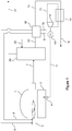
- Figure 1 shows a flame-fired glass-melting furnace 1.
- Said furnace is equipped with a number of oxy-fuel burners 2 (only one burner is show).
- the flue gas 7 evacuated from furnace 1 is supplied to the flue gas inlet of primary heat exchanger 20.
- a heat transfer fluid 22 (in casu air) is supplied to primary heat exchanger 20 via a heat transfer fluid inlet.
- said heat transfer fluid 22 is heated to a temperature of 700°C by heat exchange with hot flue gases 7.
- the tempered flue gas 21 leaves primary heat exchanger 20 via its flue-gas outlet and is sent to a flue gas treatment installation (not shown) before being sent to the stack (not shown).
- the heated heat-transfer fluid 33 is evacuated from primary heat exchanger 20 via its heat-transfer fluid outlet and introduced into secondary heat exchanger 30 via the heat-transfer fluid inlet of the latter.
- Secondary heat exchanger 30 is a multiflux heat exchanger having an oxidant inlet and an oxidant outlet as well as a fuel inlet and a fuel outlet.
- oxygen-rich oxidant 32 having an oxygen content of from 90% vol to 100% vol and gaseous fuel 31 such as natural gas are preheated by heat exchange with the hot heat transfer fluid 33.
- the thus preheated oxygen-rich oxidant 5 and gaseous fuel 6 are supplied to oxy-burners 2 of the furnace 1 so as to generate combustion and therefore heat within furnace 1, said heat being used to melt solid glass-making materials and generate a glass-melt bath in the glass tank 3 situated in the lower part of furnace 1.
- multi-flux heat exchanger 30 instead of multi-flux heat exchanger 30, it is equally possible to use two distinct secondary heat exchangers (in series or in parallel with respect to the flow of the heat transfer fluid), a first secondary heat exchanger being used to preheat the oxygen-rich oxidant 32, the second secondary heat exchanger being used to preheat the (gaseous) fuel 31.
- the residual heat present in the heat-transfer fluid 15 leaving the secondary heat exchanger is exploited and used to heat a working fluid 13 of a Rankine cycle in tertiary heat exchanger 14.
- the heat thus absorbed by working fluid 13 is used to generate mechanical power.
- Said mechanical power is then transformed into electrical power by electricity generator 10, said electrical power being supplied to the boosting electrodes 4 located in the melt basin 3 of furnace 1 (only a single electrode is shown) so as to provide electric boosting energy to the glass melt, thereby improving the efficiency of the said furnace 1.
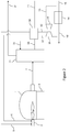
- Figure 2 shows a glass-melting installation similar to the one shown in figure 1 , except that the hot heat transfer fluid 33 is first supplied to the Ranking cycle as a heat source, whereafter the tempered heat transfer fluid 15 leaving the Rankine cycle is introduced as a heat-source fluid into secondary heat exchanger 30
- 3400 Nm/h industrial oxygen, of 95% purity, at 550°C and 1500 Nm3/h of natural gas (6) at 450°C are supplied to a glass furnace equipped with 10 burners for producing 440 tpd of soda-lime silica glass.
- the glass tank is also heated with 1600 kWe generated by means of electrodes.
- the fumes leave the furnace (1) at 1400°C.
- fumes with a volume of 7400 Nm3/h at 1250°C are obtained.
- Two primary heat exchangers, one located next to each side wall of the furnace, allow heating a stream of 9200 Nm3/h ambiant air to at 700°C.
- the fumes leave said primary heat-exchangers at 850°C.
- the generated hot air stream flows into two sets of secondary heat exchangers, one set on each side of the furnace.
- Each set comprises an oxygen and a natural gas heat-exchanger operated in series.
- Oxygen and natural gas are supplied by a valve train to the secondary heat-exchangers at a pressure around 100 to 1000 mbars.
- the residual thermal energy of this air is around 880 kW to 950 kWth.
- the organic fluid of the Rankine cycle extracts heat from these air streams at 100°C to 200°C and transforms this extracted heat into mechanical energy in an expander.
- the electric generator connected to said expander can recover up to 25% of the inlet energy, i.e. 219 kWe.
- the Organic Rankine Cycle provides 14% of the electricity needed for electric boosting.
- the electricity generated via the Rankine cycle leads to a yearly cost reduction of 202356 €.
Landscapes
- Engineering & Computer Science (AREA)
- Chemical & Material Sciences (AREA)
- Combustion & Propulsion (AREA)
- Materials Engineering (AREA)
- Organic Chemistry (AREA)
- Mechanical Engineering (AREA)
- General Engineering & Computer Science (AREA)
- Air Supply (AREA)
- Waste-Gas Treatment And Other Accessory Devices For Furnaces (AREA)
Description
- The present invention relates to processes and installations for melting vitrifiable material in a flame-fired furnace, such as, in particular, a glass-melting furnace whereby heat evacuated from the furnace together with the combustion flue gas is used for heating the furnace.
- Traditionally, flame-fired furnaces for melting vitrifiable material are operated with air as the combustion oxidant, whereby said air may be preheated upstream of the furnace by heat exchange with hot flue gas from the furnace in a regenerator or recuperator.
- More recently, the efficiency of furnaces for melting vitrifiable material has been improved by partially or totally substituting the combustion air with oxygen-enriched air or oxygen.
- In order to reduce the production costs of molten glass in glass-melting furnaces using oxygen-enriched air or oxygen as combustion oxidant, it has been proposed in inter alia
US-A-6071116 andUS-B-6250916 , to make use of the residual heat contained in the flue gas from the glass-melting furnace for heating the furnace by preheating the oxygen-enriched air or oxygen with said residual heat before the preheated combustion oxidant is introduced into the glass-melting furnace. At the start of the heat-recovery process, the temperature of the flue gas is typically from 1100°C to 1650°C. - At the end of the heat-recovery process, the temperature of the oxygen-rich oxidant can be from 300°C to 650°C.
- For reasons of security and reliability, thermal energy is not transferred directly from the hot flue gas to the oxidant, as is the case in combustion air recuperators, but is instead transferred from the hot flue gas to the oxygen-rich combustion oxidant via an intermediate heat transfer fluid, such as air, thereby ensuring that no direct contact can take place between the hot flue gas and the highly reactive oxygen-rich oxidant, even in the case of possible erosion or corrosion of the heat exchange equipment in contact with the particle-laden flue gas and corrosive (hot) oxygen-rich oxidant.
- The amount of residual heat from the flue gas which can thus be reutilized in the furnace is limited by the temperature to which the oxygen-rich oxidant can safely be preheated and, when the fuel is also preheated in the heat-recovery process, by the temperature to which the fuel can safely be preheated without deteriorating (e.g. by cracking)
- An alternative method of reducing operation costs of industrial processes in which oxygen-enhanced combustion is used, such as cement production, steel reheat applications, glass production, aluminium and copper melting and any industrial process that uses flame-fired process heaters or furnaces, is described in
US-A-2009/0308073 , whereby waste heat generated by the industrial process is sent as a heat source to an alternative Rankine cycle which converts said waste heat to power which is exported to a utility system, or which is used to reduce power requirements within the installation itself. - An intermediate fluid such as thermal oil, air or pressurized water, may be employed to transfer recoverable heat from the heat source to the working fluid of the alternative Rankine cycle.
- According to
US-A-2009/0308073 , the heat source can be a liquid or gas stream produced either as flue gas as a direct result of oxygen-enhanced combustion or as any stream utilized for cooling within the industrial process itself in order to meet the process needs. The temperature of the heat source is below 600°C, preferably between 400°C and 100°C. The examples relate to cement plants generating kiln exhaust gases with a temperature of 332°C and clinker cooler exhaust gases with a temperature of respectively 403°C and 440°C, as well as to a steel reheat furnace generating a waste heat stream at a temperature of 482°C. - The above method is clearly not suited for efficient power generation from the flue gas of a glass-melting furnace which, as indicated above, leaves the furnace at temperatures well above 1000°C.
- It is an aim of the present invention to provide an improved method of valorizing waste heat present in the flue gas from a flame-fired furnace for melting vitrifiable material which is operated with an oxygen-rich combustion oxidant for the heating of said flame-fired furnace. It is a further aim of the present invention to allow more of the waste heat present in the flue gas from a flame-fired furnace to be used for heating the furnace.
- According to the invention, this is achieved by means of the following process for melting vitrifiable material such as glass. The process comprises the following steps:
- (a) melting vitrifiable material in a flame-fired furnace (1) equipped with electric boost electrodes (4),
- (b) recovering heat from hot flue gas evacuated from the furnace by heating a heat transfer fluid by heat exchange between the heat transfer fluid and the hot flue gas;
- (c) using the heat recovered from the hot flue gas (7) to heat the flame-fired furnace (1):
- by preheating at least one reactant selected from oxygen-rich oxidant and fuel by heat exchange between said at least one reactant and the heat transfer fluid heated in step (b), so as to obtain a preheated reactant and supplying the preheated reactant thus obtained as a combustion reactant to the furnace and; and
- by supplying heat transfer fluid heated in step (b) as a heat source to a Rankine cycle so as to generate mechanical power therefrom, using at least part and preferably all of said mechanical power to produce electricity and supplying at least part of the electricity to the electric boost electrodes (4) of the furnace (1).
- Further particulars of the process according to the invention are that:
- in step (b), the temperature of the hot flue gas before heat exchange with the heat transfer fluid is at least 1000°C, preferably between 1000°C and 1350°C;
- in step (b), the heat transfer fluid is heated to a temperature of at least 600°C, preferably of between 600°C and 800°C; and
- With the process according to the invention, exploitation of the residual heat present in the hot flue gas evacuated from the furnace for heating said same furnace is optimized and maximized, resulting in a significant reduction of fuel requirements at identical pull rates of the furnace. The combination of preheating either or both the combustion reactants with heat recovery for electric boost further provides additional flexibility in the operation of the furnace, allowing, in particular to take into account changes in the pull rate or tonnage, changes in the composition of the vitrifiable material to be melted and furnace ageing.
- In the present context, the term "oxygen-rich oxidant" refers to an oxidant having an oxygen content higher than that of air, preferably containing from 50%vol to 100%vol oxygen.
- The term "heat exchange" between two fluids refers to the transfer of heat from one fluid (the heat-source fluid) to a second fluid (the fluid to be heated) without any direct contact or mixing between the two fluids.
- The term "heat exchanger" refers to a heating installation or a heating device in which a heat-source fluid, which introduces heat into the heat exchanger, and a fluid to be heated circulate in distinct enclosures or circuits, i.e. without any direct contact or mixing between said fluids, and in which heat is transferred from the heat-source fluid to the fluid to be heated across one or more walls separating the distinct disclosures or circuits.
- In the present context, two elements are "in fluid connection" with one another when they are connected so as to enable a fluid to flow from one of the elements to the other, typically by one or more fluid transport conduits.
- The term "condensibles" refers to substances present in the furnace flue gas which liquefy or solidify at temperatures in the range from 300°C to 1000°C, in particular in the range of 300°C to 880°C, at pressures in the range of 900 mbar to 1100 mbar. Sodium sulfate, borates and fluorides are examples of such condensibles which may be present in flue gas from a glass-melting furnace.
- The term "preheating" refers to the heating of a vitrifiable material or of a combustion reactant before it is introduced into a furnace.
- The heat present in the flue gas evacuated from the furnace is called "residual heat" by the person skilled in the art because said heat has been evacuated from the furnace without having been absorbed by the vitrificable material.
- In the present context, the term "Rankine cycle" can refer both to the Rankine cycle process and to a Rankine cycle unit for performing a Rankine cycle process.
- In step (b) of the process of the invention, the hot flue gas is the heat-source fluid and the heat transfer fluid is the fluid to be heated. In step (b), the heat transfer fluid is heated by heat exchange with the hot flue gas in a heat exchanger, known in the art as a "recuperator", and hereafter referred to as the primary heat exchanger.
- In the reactant preheating part of step (c), the heated heat transfer fluid is the heat-source fluid and the reactant is the fluid to be heated.
- In the Rankine part of step (c) the heated heat transfer fluid is again the heat-source fluid and the working fluid of the Rankine cycle (see below) is the fluid to be heated.
- It is an advantage of the present invention that more thermal energy recovered from the hot flue gas can be used for heating the furnace.
- According to one preferred embodiment of the process according to the invention, in step (c), the heat transfer fluid heated in step (b) is first used to preheat the at least one reactant and is then supplied as a heat source to the Rankine cycle.
- In that case, one obtains after the preheating of the at least one reactant the at least one preheated reactant and a tempered heat transfer fluid at a temperature of at most 650°C, preferably from 200°C to 650°C. The tempered heat transfer fluid is then supplied to the Rankine cycle. The temperature of the tempered heat transfer fluid after the preheating of the at least one reactant may usefully be not more than 400°C, preferably from 200°C to 400°C.
- According to an alternative embodiment, in step (c), the heat transfer fluid heated in step (b) is first supplied as a heat source to the Rankine cycle so as to generate mechanical power and obtain a tempered heat transfer fluid, and the tempered heat transfer fluid is then used to preheat the at least one reactant.
- According to one advantageous embodiment, the heating of the heat transfer fluid in step (b) and the preheating of the reactant(s) in step (c) take place in separate heat transfer installations. In that case, the heating of the heat transfer fluid takes place in the abovementioned primary heat exchanger, whereas the preheating of the reactant(s) takes place in a separate heat exchanger hereafter referred to as "secondary heat exchanger".
- The heat transfer fluid is preferably a gaseous heat transfer fluid. Examples of useful gaseous heat transfer fluids are air, CO2, N2 or mixtures of at least two of these gases. Air is usually preferred as a heat transfer fluid due to its safety and availability.
- Step (c) preferably includes preheating both oxygen-rich oxidant and fuel. Both the preheated oxygen-rich oxidant and the preheated fuel are then advantageously supplied as combustion reactants to the furnace.
- Two distinct secondary heat exchangers may be used for preheating the reactants: a secondary oxidant heat exchanger for preheating the oxygen-rich oxidant and a secondary fuel heat exchanger for preheating the fuel.
- The secondary oxidant heat exchanger and the secondary fuel heat exchanger may be disposed in series or in parallel (with respect to the flow of the heat transfer fluid). They are preferably disposed in series with the secondary oxidant heat exchanger advantageously preceding the secondary fuel heat exchanger although it is also possible to preheat the two reactants in the reverse order.
- It is also possible to preheat oxygen-rich oxidant and fuel in one specifically designed secondary heat exchanger, such a secondary heat exchanger having separate circulation paths or flow paths for the oxygen-rich oxidant and for the fuel.
- Fuels suitable for use in the process according to the invention include gaseous fuels, such as natural gas, wood gas, coal gas or syngas, liquid fuels, such as fuel oil, including light and heavy fuel oil, and solid fuels, such as particulate coal and petcoke.
- A combination of different fuels may also be burnt in the furnace. Solid fuels are typically injected into the furnace as fluid-propelled or fluid-entrained particulate solid fuel, whereby the fluid may be liquid or gaseous. In that case, the preheating of the fuel in step (c) of the process may take the form of preheating the fluid-entrained solid fuel as such, for example, in the case of a liquid-entrained solid fuel, the preheating of the slurry, or, alternatively, the form of preheating the gaseous or liquid entrainment fluid before it is used to propel or entrain the particulate solid fuel.
- When liquid fuel is injected into the furnace by means of gas-assisted atomization, the preheating of the fuel in step (c) of the process may take the form of preheating the liquid fuel before its atomization, the preheating of the gas before it is used for the atomization gas-assisted atomization of the liquid fuel, or the preheating of both the liquid fuel and the gas. When the liquid fuel is highly viscous, preheating the liquid fuel also has the advantage of lowering its viscosity.
- The oxygen-rich oxidant advantageously has an oxygen content of from 80%vol to 100%vol, preferably of at least 90%vol, more preferably of at least 95%vol, most preferably of at least 98%vol.
- Examples of temperature ranges to which a combustion reactant may be preheated in step (c) are listed in table 1.
Table 1 Reactant Preheating Temperature [°C] Oxidant with 70 to 89%vol oxygen 300°C to 700°C Oxidant with 90 to 100%vol oxygen 300°C to 650°C Natural gas 200°C to 550°C - When the fuel is a gaseous fuel, it is preferably preheated to at least 400°C in step (c). When the fuel is a liquid fuel, the liquid fuel is itself preferably preheated to at least 100°C. The maximum preheating temperature of the fuel is selected so that it is below the temperatures at which the fuel in question is subjected to thermal degradation, for example by fuel cracking.
- Different types of Rankine cycles may be used in the process according to the invention. The Rankine cycle may, for example, use water/steam as its working fluid. The Rankine cycle may also use an organic fluid, such as n-pentane or toluene, as its working fluid. The nature of the working fluid is typically selected in function of the temperature range in which the Rankine cycle must operate, this temperature being at least in part determined by the temperature at which the heat-transfer fluid is supplied as heat-source fluid to the Rankine cycle in step (c). In said step (c), the heat-transfer fluid typically heats the working fluid of the Rankine cycle, i.e. the fluid to be heated, in a further heat exchanger, referred to as "tertiary heat exchanger".
- The mechanical power generated by the Rankine cycle in step (c) is, at least in part, used to produce electricity. According to the present invention at least part of the electricity produced is used to generate electric boosting in the glass-melting furnace and is therefore supplied to electric boosting electrodes in the furnace.
- When the Rankine cycle generates more mechanical power than required for generating the electricity for electric boosting, the additional powermay be used in a wide range of applications, whereby uses which reduce the energy requirements/dependency of the furnace/of the melting process are preferred.
- The additional mechanical power generated by the Rankine cycle may for example be used to (help) compress the oxygen-rich oxidant before it is supplied to the furnace or, if the oxygen-rich oxidant is preheated in step (c), to (help) compress the oxygen-rich oxidant before it is preheated.
- The process of the present invention is suitable for essentially all types flame-fired glass-melting furnaces, such as furnaces for the production of flat glass, furnaces for the production of container glass, for the production of glass tableware, etc., and for all sizes of flame-fired glass-melting furnaces, for example with pull rates ranging from 100 to 800 tpd of molten glass.
- The present invention also relates to an installation for melting vitrifiable material, such as glass, suitable for use in the process as described above.
- Said installation for melting vitrifiable material comprises a flame-fired melting furnace having a flue gas exhaust, at least one fuel inlet, at least one combustion oxidant inlet and electric boost electrodes.
- The installation also comprises a primary heat exchanger having a flue gas inlet, a flue gas outlet, a heat transfer fluid inlet and a heat transfer fluid outlet.
- The installation further includes a secondary heat exchanger having a heat transfer fluid inlet, a heat transfer fluid outlet, a reactant inlet and a reactant outlet.
- In addition, a Rankine cycle for generating mechanical power and an electricity generator are also part of the installation according to the invention, whereby the Rankine cycle is adapted to operate with a working fluid and comprises a tertiary heat exchanger.
- The primary heat exchanger is adapted to heat the heat transfer fluid by heat exchange with the flue gas from the furnace.
- Thereto, the flue gas inlet of the primary heat exchanger is in fluid connection with the flue gas exhaust of the furnace. Its heat transfer fluid inlet is in fluid connection with a source of heat transfer fluid.
- The secondary heat exchanger is adapted to preheat at least one reactant selected from oxygen-rich oxidant and fuel by heat exchange with the heat transfer fluid. Thereto, the heat transfer fluid inlet of the secondary heat exchanger is in fluid connection with the heat transfer fluid outlet of the primary heat exchanger. The reactant inlet of the secondary heat exchanger is in fluid connection with a source of the reactant. If the reactant is oxygen-rich oxidant, the reactant outlet of the secondary heat exchanger is in fluid connection with a combustion oxidant inlet of the furnace, for example: a combustion oxidant inlet of one or more burners of the furnace. If the reactant is fuel, the reactant outlet of the secondary heat exchanger is in fluid connection with a fuel inlet of the furnace.
- The secondary heat exchanger may also comprise multiple reactant inlets and multiple reactant outlets, for example an oxygen-rich oxidant inlet in fluid connection with a source of oxygen-rich oxidant and an oxygen-rich oxidant outlet in fluid connection with a combustion oxidant inlet of the furnace, as well as a fuel inlet in fluid connection with a fuel source and a fuel outlet in fluid connection with a fuel inlet of the furnace.
- As explained above with respect to the process according to the invention, when the fuel is a fluid-entrained or fluid-propelled particulate solid fuel, the secondary heat exchanger may comprise an inlet for the fluid-entrained or - propelled solid fuel in fluid connection with a source of fluid-propelled or -entrained solid fuel and an outlet for said fluid-entrained or -propelled solid fuil in fluid connection with a fuel inlet of the furnace. Alternatively, the secondary heat exchanger may comprise an inlet for the entrainment fluid used for entraining or propelling the solid fuel in fluid connection with a source of said entrainment fluid and an outlet for said entrainment fluid, whereby said fluid outlet is in fluid connection with a fuel inlet of the furnace via a device for mixing the fluid with the particulate solid fuel.
- When the fuel is a liquid fuel, the secondary heat exchanger may comprise an inlet for the liquid fuel in fluid connection with a source of said liquid fuel and a liquid fuel outlet in fluid connection with a fuel inlet of the furnace, said fuel inlet being typically equipped with an atomizer for generating a spray of the preheated liquid fuel, whereby said atomizer may be gas assisted or not. Alternatively or in combination with the above, when a gas-assisted atomizer is used for generating a spray of liquid fuel in the furnace, the secondary heat exchanger may comprise an inlet for the atomization gas used for generating said spray, in fluid connection with a source of said atomization gas, as well as an outlet for said atomization gas, whereby said gas outlet is in fluid connection via a fuel inlet of the furnace equipped with a gas-assisted fuel atomizer.
- The tertiary heat exchanger of the Rankine cycle is adapted for heating the working fluid by heat exchange with the heat transfer fluid. Said tertiary heat exchanger presents a heat transfer fluid inlet, a heat transfer fluid outlet, a working fluid inlet and a working fluid outlet.
- The electricity generator is connected to the Rankine cycle and is adapted to transform at least part of the mechanical power generated by the Rankine cycle into electricity. The electricity generator is further connected to the boosting electrodes so as to permit supplying generated electricity thereto.
- According to a preferred embodiment the heat transfer fluid inlet of the secondary heat exchanger is in fluid connection with the heat transfer fluid outlet of the primary heat exchanger and the heat transfer outlet of the secondary heat exchanger is in fluid connection with the heat transfer fluid inlet of the tertiary heat exchanger.
- Alternatively, the heat transfer fluid inlet of the tertiary heat exchanger may be in fluid connection with the heat transfer fluid outlet of the primary heat exchanger with the heat transfer outlet of the tertiary heat exchanger being in fluid connection with the heat transfer fluid inlet of the secondary heat exchanger.
- Specific embodiments described hereabove with respect to the process of the invention also apply to the installation of the invention.
- Thus, the source of heat transfer fluid may be a source of a heat transfer fluid selected among the group of air, CO2, N2 or mixtures of at least two of gases.
- The source of heat transfer fluid is advantageously a source of a gaseous heat transfer fluid. For example, when the heat transfer fluid is air, the source of heat transfer fluid may be an air pump or compressor with which the heat-transfer fluid inlet of the primary heat exchanger is in fluid connection.
- According to one embodiment of the installation according to the invention, the secondary heat exchanger is adapted to preheat both oxygen-rich oxidant and fuel by heat exchange with the heat-transfer fluid. Said secondary heat exchanger has a first reactant inlet and a second reactant inlet, as well as a first reactant outlet and a second reactant outlet. The first reactant inlet is in fluid connection with a source of oxygen-rich oxidant. The first reactant outlet is in fluid connection with a combustion oxidant inlet of the furnace. The second reactant inlet is in fluid connection with a fuel source. The second reactant outlet is in fluid connection with a fuel inlet of the furnace.
- According to another embodiment, the oxygen-rich oxidant and the fuel are preheated in separate heat exchangers. The installation then comprises a first secondary heat exchanger which is a secondary oxidant heat exchanger and a second secondary heat exchanger which is a secondary fuel heat exchanger. The first secondary heat exchanger, i.e. the secondary oxidant heat exchanger, has a reactant inlet in fluid connection with a source of oxygen-rich oxidant as well as a reactant outlet in fluid connection with a combustion inlet of the furnace. The second secondary heat exchanger, i.e. the secondary fuel heat exchanger, has a reactant inlet in fluid connection with a source of fuel and a reactant outlet in fluid connection with a fuel inlet of the furnace.
- As mentioned above, the secondary oxidant heat exchanger and the secondary fuel heat exchanger may be disposed in parallel or in series with respect to the flow of the heat transfer fluid. A disposition in series is considered particularly useful, especially when the secondary oxidant heat exchanger precedes the secondary fuel heat exchanger, although the reverse order is also possible.
- The source of fuel is a source of gaseous fuel, of liquid fuel or of solid fuel. When the fuel is to be preheated in a secondary heat exchanger, the fuel to be preheated is preferably a gaseous fuel or a liquid fuel.
- The source of oxygen-rich oxidant is a source of an oxidant having an oxygen content higher than that of air (which is 21%vol) and advantageously between 50%vol and 100%vol. The oxygen-rich oxidant supplied by said source usefully has an oxygen content of at least 80%vol%vol, preferably of at least 90%vol, more preferably of at least 95%vol and most preferably of at least 98%vol.
- Examples of such sources are air separation units, oxygen pipelines and liquid-oxygen reservoirs.
- The working fluid of the Rankine cycle may be water/steam. It may also be an organic working fluid.
- The nature of the working fluid is selected in function of the temperature range at which the Rankine cycle operates, certain organic working fluids being, for example, particularly efficient for Rankine cycles operating at lower temperature ranges.
- If more mechanical power than necessary for electric boosting is generated by the Rankine cycle, some of the generated mechanical power may be used to compress the oxygen-rich oxidant before it is supplied as a combustion reactant to the furnace. When, as is preferred, the oxygen-rich oxidant is preheated in step (c) of the process, said surplus mechanical power is preferably used to compress the oxygen-rich oxidant before it is preheated. Indeed, certain sources of oxygen-rich oxidant such as VSA (Vacuum Swing Adsoption) air separation units frequently generate oxydant-rich oxidant at a pressure which is too low for the use of said oxygen-rich oxidant as a combustion reactant in the furnace.
- The installation is of particular interest when the furnace is a glass-melting furnace. As mentioned above, the present invention is applicable to essentially all flame-fired glass-melting furnaces. A glass-melting furnace of the installation may thus be a furnace for the production of flat glass, a furnace for the production of container glass, a furnace for the production of glass tableware, etc. The pull rate of such a glass-melting furnace may, for example, range from 100 to 800 tpd of molten glass.
- The present invention and its advantage are illustrated in the following examples, reference being made to
figures 1 and2 which are schematic representations of glass-melting installations according to the present invention. -
Figure 1 shows a flame-fired glass-meltingfurnace 1. Said furnace is equipped with a number of oxy-fuel burners 2 (only one burner is show). Theflue gas 7 evacuated fromfurnace 1 is supplied to the flue gas inlet ofprimary heat exchanger 20. Simultaneously, a heat transfer fluid 22 (in casu air) is supplied toprimary heat exchanger 20 via a heat transfer fluid inlet. - Inside
primary heat exchanger 20, saidheat transfer fluid 22 is heated to a temperature of 700°C by heat exchange withhot flue gases 7. - The tempered
flue gas 21 leavesprimary heat exchanger 20 via its flue-gas outlet and is sent to a flue gas treatment installation (not shown) before being sent to the stack (not shown). - The heated heat-
transfer fluid 33 is evacuated fromprimary heat exchanger 20 via its heat-transfer fluid outlet and introduced intosecondary heat exchanger 30 via the heat-transfer fluid inlet of the latter. -
Secondary heat exchanger 30 is a multiflux heat exchanger having an oxidant inlet and an oxidant outlet as well as a fuel inlet and a fuel outlet. - In
secondary heat exchanger 30, oxygen-rich oxidant 32 having an oxygen content of from 90% vol to 100% vol andgaseous fuel 31 such as natural gas are preheated by heat exchange with the hotheat transfer fluid 33. The thus preheated oxygen-rich oxidant 5 andgaseous fuel 6 are supplied to oxy-burners 2 of thefurnace 1 so as to generate combustion and therefore heat withinfurnace 1, said heat being used to melt solid glass-making materials and generate a glass-melt bath in theglass tank 3 situated in the lower part offurnace 1. - It will be appreciated that, instead of
multi-flux heat exchanger 30, it is equally possible to use two distinct secondary heat exchangers (in series or in parallel with respect to the flow of the heat transfer fluid), a first secondary heat exchanger being used to preheat the oxygen-rich oxidant 32, the second secondary heat exchanger being used to preheat the (gaseous)fuel 31. - In accordance with the present invention, the residual heat present in the heat-
transfer fluid 15 leaving the secondary heat exchanger, for example at about 400°C, is exploited and used to heat a workingfluid 13 of a Rankine cycle intertiary heat exchanger 14. - By means of the
power unit 12 of the Rankine cycle, the heat thus absorbed by workingfluid 13 is used to generate mechanical power. Said mechanical power is then transformed into electrical power byelectricity generator 10, said electrical power being supplied to the boostingelectrodes 4 located in themelt basin 3 of furnace 1 (only a single electrode is shown) so as to provide electric boosting energy to the glass melt, thereby improving the efficiency of the saidfurnace 1. -
Figure 2 shows a glass-melting installation similar to the one shown infigure 1 , except that the hotheat transfer fluid 33 is first supplied to the Ranking cycle as a heat source, whereafter the temperedheat transfer fluid 15 leaving the Rankine cycle is introduced as a heat-source fluid intosecondary heat exchanger 30 - 3400 Nm/h industrial oxygen, of 95% purity, at 550°C and 1500 Nm3/h of natural gas (6) at 450°C are supplied to a glass furnace equipped with 10 burners for producing 440 tpd of soda-lime silica glass. The glass tank is also heated with 1600 kWe generated by means of electrodes. The fumes leave the furnace (1) at 1400°C. Following dilution with ambient air, fumes with a volume of 7400 Nm3/h at 1250°C are obtained. Two primary heat exchangers, one located next to each side wall of the furnace, allow heating a stream of 9200 Nm3/h ambiant air to at 700°C. The fumes leave said primary heat-exchangers at 850°C. The generated hot air stream flows into two sets of secondary heat exchangers, one set on each side of the furnace. Each set comprises an oxygen and a natural gas heat-exchanger operated in series. Oxygen and natural gas are supplied by a valve train to the secondary heat-exchangers at a pressure around 100 to 1000 mbars.
- The air streams exit the sets of secondary heat exchangers on each side at a temperature of 250°C to 300°C. The residual thermal energy of this air is around 880 kW to 950 kWth.
- The organic fluid of the Rankine cycle extracts heat from these air streams at 100°C to 200°C and transforms this extracted heat into mechanical energy in an expander. The electric generator connected to said expander can recover up to 25% of the inlet energy, i.e. 219 kWe. In this case, the Organic Rankine Cycle provides 14% of the electricity needed for electric boosting. At 105 €/MWh, the electricity generated via the Rankine cycle leads to a yearly cost reduction of 202356 €.
Claims (13)
- Process for melting vitrifiable material comprising the steps of:a) melting vitrifiable material in a flame-fired furnace (1) equipped with electric boost electrodes (4),b) recovering heat from hot flue gas (7) evacuated from the furnace (1) at a temperature of at least 1100°C, preferably of between 1100°C and 1500°C by heating a heat transfer fluid (22) to a temperature of at least 600°C, preferably between 600°C and 800°C, by heat exchange between the heat transfer fluid and said hot flue gas (7); andc) using the heat recovered from the hot flue gas (7) in step (b) to heat the flame-fired furnace (1):• by preheating at least one reactant selected from oxygen-rich oxidant (32) and fuel (31) by heat exchange between said at least one reactant (32, 31) and the heat transfer fluid (33) heated in step (b), so as to obtain a preheated reactant (5, 6) and supplying the preheated reactant (5, 6) thus obtained as a combustion reactant to the furnace (1), and• by supplying heat transfer fluid (33) heated in step (b) as a heat source to a Rankine cycle so as to generate mechanical power therefrom, using at least part and preferably all of said mechanical power to produce electricity and supplying at least part of the electricity to the electric boost electrodes (4) of the furnace (1).
- Process according to claim 1 whereby, in step (c), the heat transfer fluid (33) heated in step (b) is first used to preheat the at least one reactant, thereby obtaining at least one preheated reactant and tempered heated heat transfer fluid (15) at a temperature of at most 650°C, preferably from 200°C to 650°C, and whereby thereafter the tempered heated heat transfer fluid (15) is supplied as a heat source to the Rankine cycle.
- Process according to claim 1 whereby, in step (c), the heat transfer fluid (33) heated in step (b) is first supplied as a heat source to the Rankine cycle so as to generate mechanical power and obtain a tempered heated heat transfer fluid, and whereby thereafter the tempered heated heat transfer fluid is used to preheat the at least one reactant.
- Process according to claim 1 or 2, whereby the heating of the heat transfer fluid in step (b) and the preheating of the reactant in step (c) take place in separate heat transfer installations (20, 30).
- Process according to any one of the preceding claims, whereby the heat transfer fluid (22, 33, 15) is a gaseous heat transfer fluid.
- Process according to any one of the preceding claims, whereby step (c) comprises preheating both oxygen-rich oxidant (32) and fuel (31) and whereby thereafter both the preheated oxygen-rich oxidant (5) and the preheated fuel (6) are supplied as combustion reactants to the furnace (1).
- Process according to any one of the preceding claims, whereby the oxygen-rich oxidant (32, 5) has an oxygen content of from 80%vol to 100%vol, preferably of at least 90%vol, more preferably of at least 95%vol, most preferably of at least 99%vol.
- Process for melting glass according to any of the preceding claims.
- Installation for melting vitrifiable material comprising:• a flame-fired melting furnace (1) having a flue gas exhaust, at least one fuel inlet,at least one combustion oxidant inlet and electric boost electrodes,• a primary heat exchanger (20) having a flue gas inlet, a flue gas outlet, a heat transfer fluid inlet and a heat transfer fluid outlet, the flue gas inlet being in fluid connection with the flue gas exhaust of the furnace (1), the heat transfer fluid inlet being in fluid connection with a source of heat transfer fluid, the primary heat exchanger (20) being adapted to heat the heat transfer fluid (22) by heat exchange with the flue gas (7) from the furnace (1),• a secondary heat exchanger (30) having a heat transfer fluid inlet, a heat transfer fluid outlet, a reactant inlet and a reactant outlet, the reactant inlet being in fluid connection with a source of a reactant selected from oxygen-rich oxidant (32) and fuel (31), the secondary heat exchanger (30) being adapted to preheat the reactant (32, 31) by heat exchange with the heat transfer fluid (33), whereby, if the reactant is fuel (31), the reactant outlet is in fluid connection with a fuel inlet of the furnace (1) and whereby if the reactant is oxygen-rich oxidant (32), the reactant outlet is in fluid connection with a combustion oxidant inlet of the furnace (1),• a Rankine cycle for generating mechanical power and operating with a working fluid (13) and comprising a tertiary heat exchanger (14) having a heat transfer fluid inlet, a heat transfer fluid outlet, a working fluid inlet and a working fluid outlet, the heat transfer inlet of the tertiary heat exchanger (14) being in fluid connection with the heat transfer fluid outlet of the secondary heat exchanger (30), the tertiary heat exchanger (14) being adapted for heating the working fluid (13) by heat exchange with the heat transfer fluid (15),• an electricity generator (10) connected to the Rankine cycle and adapted to transform at least part of the generated mechanical power into electricitywhereby the electricity generator (10) is connected to the boosting electrodes so as to supply electricity thereto and
whereby either:• the heat transfer fluid inlet of the secondary heat exchanger (30) is in fluid connection with the heat transfer fluid outlet of the primary heat exchanger (20) and the heat transfer outlet of the secondary heat exchanger (30) is in fluid connection with the heat transfer fluid inlet of the tertiary heat exchanger (14), or• the heat transfer fluid inlet of the tertiary heat exchanger (14) is in fluid connection with the heat transfer fluid outlet of the primary heat exchanger (20) and the heat transfer outlet of the tertiary heat exchanger (14) is in fluid connection with the heat transfer fluid inlet of the secondary heat exchanger (30). - Installation according to claim 9, whereby the source of heat transfer fluid (22) is a source of a gaseous heat transfer fluid.
- Installation according to claim 9 or 10, whereby the secondary heat exchanger (30) has a first reactant inlet, a second reactant inlet, a first reactant outlet and a second reactant outlet, the first reactant inlet being in fluid connection with a source of oxygen-rich oxidant (32) and the second reactant inlet being in fluid connection with a source of fuel (31), the secondary heat exchanger (30) being adapted to preheat the oxygen-rich oxidant (32) and the fuel (31) by heat exchange with the heat transfer fluid (33), whereby the first reactant outlet is in fluid connection with a combustion oxidant inlet of the furnace (1) and the second reactant outlet is in fluid connection with a fuel inlet of the furnace (1).
- Installation according to any one of claims 9 to 11, comprising a secondary oxidant heat exchanger and a secondary fuel heat exchanger,- the secondary oxidant heat exchanger having a reactant inlet in fluid connection with a source of oxygen-rich oxidant and a reactant outlet in fluid connection with a combustion oxidant inlet of the furnace (1),- the secondary fuel heat exchanger having a reactant inlet in fluid connection with a source of fuel and a reactant outlet in fluid connection with a fuel inlet of the furnace (1).
- Installation according to any one of claims 9 to 12, whereby the furnace (1) is a glass-melting furnace.
Applications Claiming Priority (3)
| Application Number | Priority Date | Filing Date | Title |
|---|---|---|---|
| EP14307144 | 2014-12-22 | ||
| EP14307143.9A EP3037391A1 (en) | 2014-12-22 | 2014-12-22 | Energy-efficient process and installation for melting vitrifiable material in a flame fired furnace |
| PCT/EP2015/081091 WO2016102629A1 (en) | 2014-12-22 | 2015-12-22 | Energy-efficient process and installation for melting vitrifiable material in a flame fired furnace |
Publications (2)
| Publication Number | Publication Date |
|---|---|
| EP3237344A1 EP3237344A1 (en) | 2017-11-01 |
| EP3237344B1 true EP3237344B1 (en) | 2018-10-17 |
Family
ID=55273193
Family Applications (1)
| Application Number | Title | Priority Date | Filing Date |
|---|---|---|---|
| EP15830980.7A Not-in-force EP3237344B1 (en) | 2014-12-22 | 2015-12-22 | Energy-efficient process and installation for melting vitrifiable material in a flame fired furnace |
Country Status (4)
| Country | Link |
|---|---|
| EP (1) | EP3237344B1 (en) |
| ES (1) | ES2701246T3 (en) |
| TR (1) | TR201818624T4 (en) |
| WO (1) | WO2016102629A1 (en) |
Families Citing this family (6)
| Publication number | Priority date | Publication date | Assignee | Title |
|---|---|---|---|---|
| KR102308619B1 (en) | 2017-03-20 | 2021-10-06 | 코닝 인코포레이티드 | Glass product manufacturing apparatus |
| CA3080927A1 (en) * | 2017-11-08 | 2019-05-16 | Plasma Tech Holdings, Llc | Efficient fiber manufacturing |
| KR102572097B1 (en) * | 2018-03-02 | 2023-08-30 | 프랙스에어 테크놀로지, 인코포레이티드 | Flame image analysis for furnace combustion control |
| KR102533230B1 (en) | 2018-06-22 | 2023-05-17 | 코닝 인코포레이티드 | Apparatus for manufacturing glass product and method of manufacturing glass product |
| IT202100024635A1 (en) * | 2021-09-27 | 2023-03-27 | Univ Degli Studi Genova | Heat exchange units for glass furnaces |
| WO2024068764A1 (en) * | 2022-09-27 | 2024-04-04 | Nef-Ko Ag | Method of operating a melting apparatus, melting apparatus and system for operating a melting apparatus |
Family Cites Families (7)
| Publication number | Priority date | Publication date | Assignee | Title |
|---|---|---|---|---|
| US6071116A (en) * | 1997-04-15 | 2000-06-06 | American Air Liquide, Inc. | Heat recovery apparatus and methods of use |
| ZA200304880B (en) * | 2003-02-24 | 2004-05-04 | Air Liquide | Integrated heat recovery systems and methods for increasing the efficiency of an oxygen-fired furnace. |
| WO2008013843A2 (en) * | 2006-07-26 | 2008-01-31 | Praxair Technology, Inc. | Oxygen enhanced combustion in industrial processes |
| JP5980920B2 (en) * | 2011-07-15 | 2016-08-31 | レール・リキード−ソシエテ・アノニム・プール・レテュード・エ・レクスプロワタシオン・デ・プロセデ・ジョルジュ・クロード | Glass melting apparatus and method |
| EP2546204A1 (en) * | 2011-07-15 | 2013-01-16 | L'air Liquide, Societe Anonyme Pour L'etude Et L'exploitation Des Procedes Georges Claude | Method and installation for melting glass |
| EP2551243A1 (en) * | 2011-07-26 | 2013-01-30 | L'air Liquide, Societe Anonyme Pour L'etude Et L'exploitation Des Procedes Georges Claude | Hybrid facility and method for melting glass |
| WO2014157349A1 (en) * | 2013-03-27 | 2014-10-02 | AvanStrate株式会社 | Method for manufacturing glass substrate and device for manufacturing glass substrate |
-
2015
- 2015-12-22 TR TR2018/18624T patent/TR201818624T4/en unknown
- 2015-12-22 WO PCT/EP2015/081091 patent/WO2016102629A1/en not_active Ceased
- 2015-12-22 EP EP15830980.7A patent/EP3237344B1/en not_active Not-in-force
- 2015-12-22 ES ES15830980T patent/ES2701246T3/en active Active
Non-Patent Citations (1)
| Title |
|---|
| None * |
Also Published As
| Publication number | Publication date |
|---|---|
| ES2701246T3 (en) | 2019-02-21 |
| TR201818624T4 (en) | 2019-01-21 |
| WO2016102629A1 (en) | 2016-06-30 |
| EP3237344A1 (en) | 2017-11-01 |
Similar Documents
| Publication | Publication Date | Title |
|---|---|---|
| EP3237344A1 (en) | Energy-efficient process and installation for melting vitrifiable material in a flame fired furnace | |
| EP1338848B1 (en) | Method and apparatus for integrated air separation and heat recovery in a furnace | |
| US8851883B2 (en) | Preheating of fuel and oxidant of oxy-burners, using combustion air preheating installations | |
| JP5275296B2 (en) | Integrated heat recovery system and method for increasing the efficiency of oxyfuel combustion furnaces | |
| CN102227384B (en) | Furnace with multiple heat recovery systems | |
| CN104870383B (en) | Energy recovery from fumes from furnaces with gas turbines and heat exchangers | |
| US10208952B2 (en) | Combustion method and installation with optimized energy recuperation | |
| WO2008013843A2 (en) | Oxygen enhanced combustion in industrial processes | |
| CN105980776A (en) | Integrated process for oxy-fuel combustion and production of oxygen | |
| EP3237343B1 (en) | Optimized process and installation for melting vitrifiable material in a flame-fired furnace | |
| CN104870382B (en) | Energy recovery from flue gases from melting furnaces using gas turbines and heat exchangers | |
| US20030010061A1 (en) | Methods and apparatuses related to the integration of an air separation unit and a glass facility | |
| CN106061909A (en) | Combustion with improved heat recovery | |
| EP3037391A1 (en) | Energy-efficient process and installation for melting vitrifiable material in a flame fired furnace |
Legal Events
| Date | Code | Title | Description |
|---|---|---|---|
| PUAI | Public reference made under article 153(3) epc to a published international application that has entered the european phase |
Free format text: ORIGINAL CODE: 0009012 |
|
| 17P | Request for examination filed |
Effective date: 20170724 |
|
| AK | Designated contracting states |
Kind code of ref document: A1 Designated state(s): AL AT BE BG CH CY CZ DE DK EE ES FI FR GB GR HR HU IE IS IT LI LT LU LV MC MK MT NL NO PL PT RO RS SE SI SK SM TR |
|
| AX | Request for extension of the european patent |
Extension state: BA ME |
|
| RIN1 | Information on inventor provided before grant (corrected) |
Inventor name: JOUMANI, YOUSSEF Inventor name: JARRY, LUC Inventor name: TSIAVA, REMI Inventor name: BEASSE, GREGOIRE Inventor name: LEROUX, BERTRAND Inventor name: WAGNER, MARC |
|
| DAV | Request for validation of the european patent (deleted) | ||
| DAX | Request for extension of the european patent (deleted) | ||
| RIC1 | Information provided on ipc code assigned before grant |
Ipc: F27B 3/26 20060101ALI20180404BHEP Ipc: C03B 5/235 20060101ALI20180404BHEP Ipc: F23L 15/04 20060101ALI20180404BHEP Ipc: F23L 7/00 20060101ALI20180404BHEP Ipc: F28D 21/00 20060101ALI20180404BHEP Ipc: C03B 5/237 20060101AFI20180404BHEP Ipc: F27D 17/00 20060101ALI20180404BHEP |
|
| GRAP | Despatch of communication of intention to grant a patent |
Free format text: ORIGINAL CODE: EPIDOSNIGR1 |
|
| INTG | Intention to grant announced |
Effective date: 20180511 |
|
| GRAS | Grant fee paid |
Free format text: ORIGINAL CODE: EPIDOSNIGR3 |
|
| GRAA | (expected) grant |
Free format text: ORIGINAL CODE: 0009210 |
|
| AK | Designated contracting states |
Kind code of ref document: B1 Designated state(s): AL AT BE BG CH CY CZ DE DK EE ES FI FR GB GR HR HU IE IS IT LI LT LU LV MC MK MT NL NO PL PT RO RS SE SI SK SM TR |
|
| REG | Reference to a national code |
Ref country code: GB Ref legal event code: FG4D |
|
| REG | Reference to a national code |
Ref country code: CH Ref legal event code: EP |
|
| REG | Reference to a national code |
Ref country code: IE Ref legal event code: FG4D |
|
| REG | Reference to a national code |
Ref country code: DE Ref legal event code: R096 Ref document number: 602015018490 Country of ref document: DE Ref country code: AT Ref legal event code: REF Ref document number: 1053795 Country of ref document: AT Kind code of ref document: T Effective date: 20181115 |
|
| REG | Reference to a national code |
Ref country code: NL Ref legal event code: FP |
|
| PGFP | Annual fee paid to national office [announced via postgrant information from national office to epo] |
Ref country code: NL Payment date: 20181219 Year of fee payment: 4 Ref country code: DE Payment date: 20181210 Year of fee payment: 4 |
|
| REG | Reference to a national code |
Ref country code: ES Ref legal event code: FG2A Ref document number: 2701246 Country of ref document: ES Kind code of ref document: T3 Effective date: 20190221 |
|
| PGFP | Annual fee paid to national office [announced via postgrant information from national office to epo] |
Ref country code: IT Payment date: 20181231 Year of fee payment: 4 Ref country code: FR Payment date: 20181221 Year of fee payment: 4 |
|
| REG | Reference to a national code |
Ref country code: LT Ref legal event code: MG4D |
|
| REG | Reference to a national code |
Ref country code: AT Ref legal event code: MK05 Ref document number: 1053795 Country of ref document: AT Kind code of ref document: T Effective date: 20181017 |
|
| PG25 | Lapsed in a contracting state [announced via postgrant information from national office to epo] |
Ref country code: IS Free format text: LAPSE BECAUSE OF FAILURE TO SUBMIT A TRANSLATION OF THE DESCRIPTION OR TO PAY THE FEE WITHIN THE PRESCRIBED TIME-LIMIT Effective date: 20190217 Ref country code: NO Free format text: LAPSE BECAUSE OF FAILURE TO SUBMIT A TRANSLATION OF THE DESCRIPTION OR TO PAY THE FEE WITHIN THE PRESCRIBED TIME-LIMIT Effective date: 20190117 Ref country code: BG Free format text: LAPSE BECAUSE OF FAILURE TO SUBMIT A TRANSLATION OF THE DESCRIPTION OR TO PAY THE FEE WITHIN THE PRESCRIBED TIME-LIMIT Effective date: 20190117 Ref country code: LT Free format text: LAPSE BECAUSE OF FAILURE TO SUBMIT A TRANSLATION OF THE DESCRIPTION OR TO PAY THE FEE WITHIN THE PRESCRIBED TIME-LIMIT Effective date: 20181017 Ref country code: HR Free format text: LAPSE BECAUSE OF FAILURE TO SUBMIT A TRANSLATION OF THE DESCRIPTION OR TO PAY THE FEE WITHIN THE PRESCRIBED TIME-LIMIT Effective date: 20181017 Ref country code: AT Free format text: LAPSE BECAUSE OF FAILURE TO SUBMIT A TRANSLATION OF THE DESCRIPTION OR TO PAY THE FEE WITHIN THE PRESCRIBED TIME-LIMIT Effective date: 20181017 Ref country code: PL Free format text: LAPSE BECAUSE OF FAILURE TO SUBMIT A TRANSLATION OF THE DESCRIPTION OR TO PAY THE FEE WITHIN THE PRESCRIBED TIME-LIMIT Effective date: 20181017 Ref country code: LV Free format text: LAPSE BECAUSE OF FAILURE TO SUBMIT A TRANSLATION OF THE DESCRIPTION OR TO PAY THE FEE WITHIN THE PRESCRIBED TIME-LIMIT Effective date: 20181017 Ref country code: FI Free format text: LAPSE BECAUSE OF FAILURE TO SUBMIT A TRANSLATION OF THE DESCRIPTION OR TO PAY THE FEE WITHIN THE PRESCRIBED TIME-LIMIT Effective date: 20181017 |
|
| PG25 | Lapsed in a contracting state [announced via postgrant information from national office to epo] |
Ref country code: SE Free format text: LAPSE BECAUSE OF FAILURE TO SUBMIT A TRANSLATION OF THE DESCRIPTION OR TO PAY THE FEE WITHIN THE PRESCRIBED TIME-LIMIT Effective date: 20181017 Ref country code: RS Free format text: LAPSE BECAUSE OF FAILURE TO SUBMIT A TRANSLATION OF THE DESCRIPTION OR TO PAY THE FEE WITHIN THE PRESCRIBED TIME-LIMIT Effective date: 20181017 Ref country code: AL Free format text: LAPSE BECAUSE OF FAILURE TO SUBMIT A TRANSLATION OF THE DESCRIPTION OR TO PAY THE FEE WITHIN THE PRESCRIBED TIME-LIMIT Effective date: 20181017 Ref country code: GR Free format text: LAPSE BECAUSE OF FAILURE TO SUBMIT A TRANSLATION OF THE DESCRIPTION OR TO PAY THE FEE WITHIN THE PRESCRIBED TIME-LIMIT Effective date: 20190118 Ref country code: PT Free format text: LAPSE BECAUSE OF FAILURE TO SUBMIT A TRANSLATION OF THE DESCRIPTION OR TO PAY THE FEE WITHIN THE PRESCRIBED TIME-LIMIT Effective date: 20190217 |
|
| REG | Reference to a national code |
Ref country code: DE Ref legal event code: R097 Ref document number: 602015018490 Country of ref document: DE |
|
| PG25 | Lapsed in a contracting state [announced via postgrant information from national office to epo] |
Ref country code: DK Free format text: LAPSE BECAUSE OF FAILURE TO SUBMIT A TRANSLATION OF THE DESCRIPTION OR TO PAY THE FEE WITHIN THE PRESCRIBED TIME-LIMIT Effective date: 20181017 Ref country code: CZ Free format text: LAPSE BECAUSE OF FAILURE TO SUBMIT A TRANSLATION OF THE DESCRIPTION OR TO PAY THE FEE WITHIN THE PRESCRIBED TIME-LIMIT Effective date: 20181017 |
|
| REG | Reference to a national code |
Ref country code: CH Ref legal event code: PL |
|
| PLBE | No opposition filed within time limit |
Free format text: ORIGINAL CODE: 0009261 |
|
| STAA | Information on the status of an ep patent application or granted ep patent |
Free format text: STATUS: NO OPPOSITION FILED WITHIN TIME LIMIT |
|
| PG25 | Lapsed in a contracting state [announced via postgrant information from national office to epo] |
Ref country code: SK Free format text: LAPSE BECAUSE OF FAILURE TO SUBMIT A TRANSLATION OF THE DESCRIPTION OR TO PAY THE FEE WITHIN THE PRESCRIBED TIME-LIMIT Effective date: 20181017 Ref country code: SM Free format text: LAPSE BECAUSE OF FAILURE TO SUBMIT A TRANSLATION OF THE DESCRIPTION OR TO PAY THE FEE WITHIN THE PRESCRIBED TIME-LIMIT Effective date: 20181017 Ref country code: EE Free format text: LAPSE BECAUSE OF FAILURE TO SUBMIT A TRANSLATION OF THE DESCRIPTION OR TO PAY THE FEE WITHIN THE PRESCRIBED TIME-LIMIT Effective date: 20181017 Ref country code: RO Free format text: LAPSE BECAUSE OF FAILURE TO SUBMIT A TRANSLATION OF THE DESCRIPTION OR TO PAY THE FEE WITHIN THE PRESCRIBED TIME-LIMIT Effective date: 20181017 Ref country code: MC Free format text: LAPSE BECAUSE OF FAILURE TO SUBMIT A TRANSLATION OF THE DESCRIPTION OR TO PAY THE FEE WITHIN THE PRESCRIBED TIME-LIMIT Effective date: 20181017 Ref country code: LU Free format text: LAPSE BECAUSE OF NON-PAYMENT OF DUE FEES Effective date: 20181222 |
|
| REG | Reference to a national code |
Ref country code: IE Ref legal event code: MM4A |
|
| 26N | No opposition filed |
Effective date: 20190718 |
|
| REG | Reference to a national code |
Ref country code: BE Ref legal event code: MM Effective date: 20181231 |
|
| PG25 | Lapsed in a contracting state [announced via postgrant information from national office to epo] |
Ref country code: SI Free format text: LAPSE BECAUSE OF FAILURE TO SUBMIT A TRANSLATION OF THE DESCRIPTION OR TO PAY THE FEE WITHIN THE PRESCRIBED TIME-LIMIT Effective date: 20181017 Ref country code: IE Free format text: LAPSE BECAUSE OF NON-PAYMENT OF DUE FEES Effective date: 20181222 |
|
| PG25 | Lapsed in a contracting state [announced via postgrant information from national office to epo] |
Ref country code: BE Free format text: LAPSE BECAUSE OF NON-PAYMENT OF DUE FEES Effective date: 20181231 |
|
| PG25 | Lapsed in a contracting state [announced via postgrant information from national office to epo] |
Ref country code: LI Free format text: LAPSE BECAUSE OF NON-PAYMENT OF DUE FEES Effective date: 20181231 Ref country code: CH Free format text: LAPSE BECAUSE OF NON-PAYMENT OF DUE FEES Effective date: 20181231 |
|
| PG25 | Lapsed in a contracting state [announced via postgrant information from national office to epo] |
Ref country code: MT Free format text: LAPSE BECAUSE OF NON-PAYMENT OF DUE FEES Effective date: 20181222 |
|
| REG | Reference to a national code |
Ref country code: ES Ref legal event code: FD2A Effective date: 20200131 |
|
| PG25 | Lapsed in a contracting state [announced via postgrant information from national office to epo] |
Ref country code: ES Free format text: LAPSE BECAUSE OF NON-PAYMENT OF DUE FEES Effective date: 20181223 |
|
| PG25 | Lapsed in a contracting state [announced via postgrant information from national office to epo] |
Ref country code: HU Free format text: LAPSE BECAUSE OF FAILURE TO SUBMIT A TRANSLATION OF THE DESCRIPTION OR TO PAY THE FEE WITHIN THE PRESCRIBED TIME-LIMIT; INVALID AB INITIO Effective date: 20151222 Ref country code: MK Free format text: LAPSE BECAUSE OF NON-PAYMENT OF DUE FEES Effective date: 20181017 Ref country code: CY Free format text: LAPSE BECAUSE OF FAILURE TO SUBMIT A TRANSLATION OF THE DESCRIPTION OR TO PAY THE FEE WITHIN THE PRESCRIBED TIME-LIMIT Effective date: 20181017 |
|
| REG | Reference to a national code |
Ref country code: DE Ref legal event code: R119 Ref document number: 602015018490 Country of ref document: DE |
|
| REG | Reference to a national code |
Ref country code: NL Ref legal event code: MM Effective date: 20200101 |
|
| GBPC | Gb: european patent ceased through non-payment of renewal fee |
Effective date: 20191222 |
|
| PG25 | Lapsed in a contracting state [announced via postgrant information from national office to epo] |
Ref country code: NL Free format text: LAPSE BECAUSE OF NON-PAYMENT OF DUE FEES Effective date: 20200101 |
|
| PG25 | Lapsed in a contracting state [announced via postgrant information from national office to epo] |
Ref country code: DE Free format text: LAPSE BECAUSE OF NON-PAYMENT OF DUE FEES Effective date: 20200701 Ref country code: GB Free format text: LAPSE BECAUSE OF NON-PAYMENT OF DUE FEES Effective date: 20191222 Ref country code: FR Free format text: LAPSE BECAUSE OF NON-PAYMENT OF DUE FEES Effective date: 20191231 Ref country code: IT Free format text: LAPSE BECAUSE OF NON-PAYMENT OF DUE FEES Effective date: 20191222 |
|
| PG25 | Lapsed in a contracting state [announced via postgrant information from national office to epo] |
Ref country code: TR Free format text: LAPSE BECAUSE OF NON-PAYMENT OF DUE FEES Effective date: 20191222 |