EP3236868B1 - System for bending a bone plate - Google Patents
System for bending a bone plate Download PDFInfo
- Publication number
- EP3236868B1 EP3236868B1 EP15821200.1A EP15821200A EP3236868B1 EP 3236868 B1 EP3236868 B1 EP 3236868B1 EP 15821200 A EP15821200 A EP 15821200A EP 3236868 B1 EP3236868 B1 EP 3236868B1
- Authority
- EP
- European Patent Office
- Prior art keywords
- bone
- drill guide
- bone plate
- bending
- extending
- Prior art date
- Legal status (The legal status is an assumption and is not a legal conclusion. Google has not performed a legal analysis and makes no representation as to the accuracy of the status listed.)
- Active
Links
- 210000000988 bone and bone Anatomy 0.000 title claims description 72
- 238000005452 bending Methods 0.000 title claims description 56
- 239000007943 implant Substances 0.000 description 3
- 210000003484 anatomy Anatomy 0.000 description 2
- 238000004891 communication Methods 0.000 description 1
- 230000001419 dependent effect Effects 0.000 description 1
- 238000005553 drilling Methods 0.000 description 1
- 238000000034 method Methods 0.000 description 1
- 238000012986 modification Methods 0.000 description 1
- 230000004048 modification Effects 0.000 description 1
- 239000011295 pitch Substances 0.000 description 1
Images

Classifications
-
- A—HUMAN NECESSITIES
- A61—MEDICAL OR VETERINARY SCIENCE; HYGIENE
- A61B—DIAGNOSIS; SURGERY; IDENTIFICATION
- A61B17/00—Surgical instruments, devices or methods
- A61B17/56—Surgical instruments or methods for treatment of bones or joints; Devices specially adapted therefor
- A61B17/58—Surgical instruments or methods for treatment of bones or joints; Devices specially adapted therefor for osteosynthesis, e.g. bone plates, screws or setting implements
- A61B17/88—Osteosynthesis instruments; Methods or means for implanting or extracting internal or external fixation devices
- A61B17/8863—Apparatus for shaping or cutting osteosynthesis equipment by medical personnel
-
- A—HUMAN NECESSITIES
- A61—MEDICAL OR VETERINARY SCIENCE; HYGIENE
- A61B—DIAGNOSIS; SURGERY; IDENTIFICATION
- A61B17/00—Surgical instruments, devices or methods
- A61B17/16—Instruments for performing osteoclasis; Drills or chisels for bones; Trepans
- A61B17/17—Guides or aligning means for drills, mills, pins or wires
- A61B17/1728—Guides or aligning means for drills, mills, pins or wires for holes for bone plates or plate screws
-
- A—HUMAN NECESSITIES
- A61—MEDICAL OR VETERINARY SCIENCE; HYGIENE
- A61B—DIAGNOSIS; SURGERY; IDENTIFICATION
- A61B17/00—Surgical instruments, devices or methods
- A61B17/56—Surgical instruments or methods for treatment of bones or joints; Devices specially adapted therefor
- A61B17/58—Surgical instruments or methods for treatment of bones or joints; Devices specially adapted therefor for osteosynthesis, e.g. bone plates, screws or setting implements
- A61B17/68—Internal fixation devices, including fasteners and spinal fixators, even if a part thereof projects from the skin
- A61B17/80—Cortical plates, i.e. bone plates; Instruments for holding or positioning cortical plates, or for compressing bones attached to cortical plates
- A61B17/8085—Cortical plates, i.e. bone plates; Instruments for holding or positioning cortical plates, or for compressing bones attached to cortical plates with pliable or malleable elements or having a mesh-like structure, e.g. small strips
-
- A—HUMAN NECESSITIES
- A61—MEDICAL OR VETERINARY SCIENCE; HYGIENE
- A61B—DIAGNOSIS; SURGERY; IDENTIFICATION
- A61B17/00—Surgical instruments, devices or methods
- A61B17/56—Surgical instruments or methods for treatment of bones or joints; Devices specially adapted therefor
- A61B17/58—Surgical instruments or methods for treatment of bones or joints; Devices specially adapted therefor for osteosynthesis, e.g. bone plates, screws or setting implements
- A61B17/68—Internal fixation devices, including fasteners and spinal fixators, even if a part thereof projects from the skin
- A61B17/80—Cortical plates, i.e. bone plates; Instruments for holding or positioning cortical plates, or for compressing bones attached to cortical plates
- A61B17/8052—Cortical plates, i.e. bone plates; Instruments for holding or positioning cortical plates, or for compressing bones attached to cortical plates immobilised relative to screws by interlocking form of the heads and plate holes, e.g. conical or threaded
- A61B17/8057—Cortical plates, i.e. bone plates; Instruments for holding or positioning cortical plates, or for compressing bones attached to cortical plates immobilised relative to screws by interlocking form of the heads and plate holes, e.g. conical or threaded the interlocking form comprising a thread
Definitions
- Implants such as, for example, bone plates, must often be contoured to a fit a patient's specific anatomy to properly fix a fracture.
- the bone plates may be bent by a surgeon or other user using bending pins slid over drill guides that are pre-assembled with the bone fixation element receiving holes of the bone plate. Forces applied to the bending pins are transferred to the drill guides attached to the bone plate until the bone plate is bent, as desired. This process, however, exerts bending forces directly to the threading formed in bone fixation element receiving holes and, in some cases, may damage the bone plate beyond usability.
- a system for bending a bone plate according to the preamble of claim 1 is known from US 2009/0318979 A1 .
- the present invention is directed to a system for bending a bone plate, comprising a drill guide extending longitudinally from a proximal end to a distal end, the drill guide including a distal portion having a first threading extending therealong to engage a threading along an interior of a bone fixation element receiving hole of an implant and a proximal portion having a second threading extending therealong and a bending pin extending longitudinally from a proximal end to a distal end including a recess extending proximally therefrom, the recess sized and shaped to receive the proximal portion of the drill guide and including a corresponding threading therealong for engaging the second threading.
- the system is characterised in that the drill guide includes a non-threaded portion extending between the proximal and distal portions. Further embodiments are defined by the dependent claims.
- a system for treating a bone is defined by claim 8.
- the present invention is directed to a system for treating a bone and, in particular, to a system for bending a bone plate to correspond to a patient's anatomy.
- exemplary embodiments of the present invention describe a system comprising a drill guide engaged within a bone fixation element receiving hole of a bone plate and a bending pin threadedly engagable with the drill guide to contact a surface of the bone plate so that bending forces applied to the bending pin are directly applied to the bone plate.
- proximal and distal refer to a direction toward (proximal) and away from (distal) a user of the device.
- a system 100 comprises a plurality of drill guides 102, each of which engages a bone fixation element receiving hole 104 of an implant such as, for example, a bone plate 106.
- the system 100 further comprises a plurality of bending pins 108, each bending pin 108 engagable with a corresponding one of the drill guides 102 so that a distal end 110 of the bending pin contacts the bone plate 106,
- a proximal surface 144 of the bone plate 106 i.e., a surface which, when the plate 106 is mounted on a target portion of bone, faces away from the bone. Applying the bending forces to the proximal surface 144 of the plate 106 prevents damage to the bone fixation element receiving holes 104 of the bone plate 106.
- conventional bending pins are slid over the drill guides, which are pre-assembled with the bone plate.
- Conventional bending pins and drill guides do not include any features that mate with one another so that, when bending forces are applied, one side of the bending pin will rise off of the plate, out of contact therewith, causing forces to be applied directly to the threads of the drill guide and the bone fixation element receiving holes of the bone plate with which the drill guides are engaged. This may cause the drill guides to back out of the bone fixation element receiving holes and/or cause extensive damage to the bone fixation element receiving holes of the bone plate. It will be understood by those of skill in the art, that the engagement of the bending pin 108 and the drill guide 102 of the present invention prevents damage to the threading of the bone fixation element receiving holes 104 of the bone plate 106 being bent thereby.
- each drill guide 102 extends longitudinally from a proximal end 112 to a distal end 114 and includes a channel 116 extending longitudinally therethrough to accommodate, for example, a drill bit for drilling a hole into a bone along an axis of the channel 116.
- the drill guide 102 include a distal portion 118 extending proximally from the distal end 114 for engaging a bone fixation element receiving hole 104 of the bone plate 106 and a proximal portion 120 extending distally from the proximal end 112 for engaging a corresponding one of the bending pins 108.
- the distal portion 118 includes a first threading 122 extending therealong for engaging a threading of the bone fixation element receiving hole 104.
- the proximal portion 120 includes a second threading 124 extending therealong for engaging a corresponding threading 126 of the bending pin 108.
- the drill guide 102 Extending between the distal portion 118 and the proximal portion 120, the drill guide 102 includes a non-threaded portion 128 that acts as a shoulder for directing force between the bending pin 108 and the drill guide 102.
- the first and second threadings 122, 124 may have different pitches.
- the distal portion 118 tapers from a proximal end 130 thereof toward the distal end 114 to engage a tapered bone fixation element receiving hole 104 (e.g., a locking screw hole).
- the proximal portion 120 may have a substantially constant cross-sectional area along a length thereof.
- the proximal portion 120 may also include a flat surface 146 extending along a length thereof.
- the proximal portion 120 includes a pair of flat surfaces 146 diametrically opposed from one another.
- the flat surfaces 146 may engage a tool which is used to assemble the drill guide 102 with the bone plate 106 so that assembling the drill guide 102 to the bone plate 106 does not cause any damage to the second threading 124 of the drill guide 102 and/or any portion of the bending pin 108, which may otherwise be used to assemble the drill guide 102 to the bone plate 106.
- each of the bending pins 108 extends longitudinally from a proximal end 132 to the distal end 110.
- the bending pin 108 includes a drill guide engaging portion 136 extending proximally from the distal end 110 and a gripping portion 138 at the proximal end 132 thereof.
- the gripping portion 138 according to this embodiment includes knurls 148 extending therealong and thereabout to facilitate a gripping thereof by a user.
- the drill guide engaging portion 136 includes a recess 140 at the distal end 110 sized and shaped to receive the proximal portion 120 of the drill guide 102,
- the recess 140 includes the threading 126 extending along a portion thereof for engaging the second threading 124 and a non-threaded portion 142 along a distal portion thereof for receiving the non-threaded portion 128 of the drill guide 102.
- the drill guide engaging portion 136 according to this embodiment also includes a pin 134 extending longitudinally within the recess 140 along a central axis thereof, as shown in Fig. 1 .
- the pin 134 is not a required feature as the engagement between the proximal portion 120 of the drill guide 102 and the drill guide engaging portion 136 of the bending pin 108 is sufficient to transfer the bending force from the bending pin 108 to the proximal surface 144 of the drill guide 102.
- Each of the bending pins 108 may also include a through-hole 150 extending laterally through the drill engaging portion 136 so that the through-hole 150 is in communication with the recess 140. The through-hole 150 may be used to clean the recess 140, including the threading 126 and the non-threaded portion 142.
- the drill guides 102 may be pre-assembled with the bone plate 106 with the distal portion 118 of each of the drill guides 102 received within a corresponding one of the bone fixation element receiving holes 104 of the bone plate 106.
- the first threading 122 of the distal portion 118 is threadedly engaged with the bone fixation element receiving hole 104 so that the proximal portion 120 and the non-threaded portion 128 extend proximally from the proximal surface 144 of the bone plate 106.
- Each of the bending pins 108 is then engaged with a corresponding one of the drill guides 102.
- the proximal portion 120 is received within the recess 140 of the bending pin 108, the bending pin 108 being rotated about a longitudinal axis thereof so that the threading 126 along the interior of the recess 140 engages the second threading 124.
- the bending pin 108 is rotated relative to the drill guide 102 until the distal end 110 contacts the proximal surface 144 of the bone plate 106 and the non-threaded portion 128 of the drill guide 102 is received within the non-threaded portion 142 at the distal end of the recess 140.
- a user grips the gripping portions 138 of first and second ones of the bending pins 108, moving the first and second bending pins 108 relative to one another to bend the bone plate 106 as desired.
- different bending pins 108 may be moved relative to one another in selected directions to bend the bone plate 106 as desired.
- the non-threaded portion 128 of the drill guide 102 within the non-threaded portion 142 of the bending pin 108 acts as a guide to direct the bending force applied to the bending pin 108 to the drill guide 102.
- the contact between the bone plate 106 and the distal end 110 of the bending pin 108 applies the bending force directly to the proximal surface 144 of the bone plate 106, preventing damage to the bone fixation element receiving holes 104.
Landscapes
- Health & Medical Sciences (AREA)
- Orthopedic Medicine & Surgery (AREA)
- Surgery (AREA)
- Life Sciences & Earth Sciences (AREA)
- Heart & Thoracic Surgery (AREA)
- Veterinary Medicine (AREA)
- Engineering & Computer Science (AREA)
- Biomedical Technology (AREA)
- Nuclear Medicine, Radiotherapy & Molecular Imaging (AREA)
- Medical Informatics (AREA)
- Molecular Biology (AREA)
- Animal Behavior & Ethology (AREA)
- General Health & Medical Sciences (AREA)
- Public Health (AREA)
- Dentistry (AREA)
- Oral & Maxillofacial Surgery (AREA)
- Neurology (AREA)
- Surgical Instruments (AREA)
Description
- Implants such as, for example, bone plates, must often be contoured to a fit a patient's specific anatomy to properly fix a fracture. The bone plates may be bent by a surgeon or other user using bending pins slid over drill guides that are pre-assembled with the bone fixation element receiving holes of the bone plate. Forces applied to the bending pins are transferred to the drill guides attached to the bone plate until the bone plate is bent, as desired. This process, however, exerts bending forces directly to the threading formed in bone fixation element receiving holes and, in some cases, may damage the bone plate beyond usability.
- A system for bending a bone plate according to the preamble of claim 1 is known from
US 2009/0318979 A1 . - The present invention is directed to a system for bending a bone plate, comprising a drill guide extending longitudinally from a proximal end to a distal end, the drill guide including a distal portion having a first threading extending therealong to engage a threading along an interior of a bone fixation element receiving hole of an implant and a proximal portion having a second threading extending therealong and a bending pin extending longitudinally from a proximal end to a distal end including a recess extending proximally therefrom, the recess sized and shaped to receive the proximal portion of the drill guide and including a corresponding threading therealong for engaging the second threading. The system is characterised in that the drill guide includes a non-threaded portion extending between the proximal and distal portions. Further embodiments are defined by the dependent claims. A system for treating a bone is defined by claim 8.
-
-
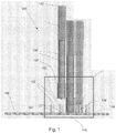
Fig. 1 shows longitudinal side view of a system according to an exemplary embodiment of the present invention; -
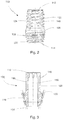
Fig. 2 shows a side view of a drill guide according to the system ofFig. 1 ; -
Fig. 3 shows a longitudinal cross-sectional view of the drill guide ofFig. 2 ; -
Fig. 4 shows a side view of a bending pin according to the system ofFig. 1 ; and -
Fig. 5 shows a partial longitudinal cross-sectional view of the bending pin ofFig. 3 . - The present invention may be further understood with reference to the following description and the appended drawings, wherein like elements are referred to with the same reference numerals. The present invention is directed to a system for treating a bone and, in particular, to a system for bending a bone plate to correspond to a patient's anatomy. Exemplary embodiments of the present invention describe a system comprising a drill guide engaged within a bone fixation element receiving hole of a bone plate and a bending pin threadedly engagable with the drill guide to contact a surface of the bone plate so that bending forces applied to the bending pin are directly applied to the bone plate. It will be understood by those of skill in the art that the terms "proximal" and "distal" refer to a direction toward (proximal) and away from (distal) a user of the device.
- As shown in
Figs. 1 - 5 , asystem 100 according to an exemplary embodiment of the present invention comprises a plurality ofdrill guides 102, each of which engages a bone fixationelement receiving hole 104 of an implant such as, for example, abone plate 106. Thesystem 100 further comprises a plurality ofbending pins 108, eachbending pin 108 engagable with a corresponding one of thedrill guides 102 so that adistal end 110 of the bending pin contacts thebone plate 106, Thus, when thebending pins 108 are moved relative to one another to bend thebone plate 106, the bending force is applied directly to aproximal surface 144 of the bone plate 106 (i.e., a surface which, when theplate 106 is mounted on a target portion of bone, faces away from the bone). Applying the bending forces to theproximal surface 144 of theplate 106 prevents damage to the bone fixationelement receiving holes 104 of thebone plate 106. In contrast, conventional bending pins are slid over the drill guides, which are pre-assembled with the bone plate. Conventional bending pins and drill guides do not include any features that mate with one another so that, when bending forces are applied, one side of the bending pin will rise off of the plate, out of contact therewith, causing forces to be applied directly to the threads of the drill guide and the bone fixation element receiving holes of the bone plate with which the drill guides are engaged. This may cause the drill guides to back out of the bone fixation element receiving holes and/or cause extensive damage to the bone fixation element receiving holes of the bone plate. It will be understood by those of skill in the art, that the engagement of thebending pin 108 and thedrill guide 102 of the present invention prevents damage to the threading of the bone fixationelement receiving holes 104 of thebone plate 106 being bent thereby. - As shown in
Figs. 2 and 3 , eachdrill guide 102 extends longitudinally from aproximal end 112 to adistal end 114 and includes achannel 116 extending longitudinally therethrough to accommodate, for example, a drill bit for drilling a hole into a bone along an axis of thechannel 116. Thedrill guide 102 include adistal portion 118 extending proximally from thedistal end 114 for engaging a bone fixationelement receiving hole 104 of thebone plate 106 and aproximal portion 120 extending distally from theproximal end 112 for engaging a corresponding one of thebending pins 108. Thedistal portion 118 includes afirst threading 122 extending therealong for engaging a threading of the bone fixationelement receiving hole 104. Theproximal portion 120 includes asecond threading 124 extending therealong for engaging a corresponding threading 126 of thebending pin 108. Extending between thedistal portion 118 and theproximal portion 120, thedrill guide 102 includes a non-threadedportion 128 that acts as a shoulder for directing force between thebending pin 108 and thedrill guide 102. The first andsecond threadings - In one exemplary embodiment, the
distal portion 118 tapers from aproximal end 130 thereof toward thedistal end 114 to engage a tapered bone fixation element receiving hole 104 (e.g., a locking screw hole). Theproximal portion 120 may have a substantially constant cross-sectional area along a length thereof. Theproximal portion 120 may also include aflat surface 146 extending along a length thereof. In an exemplary embodiment, theproximal portion 120 includes a pair offlat surfaces 146 diametrically opposed from one another. Theflat surfaces 146 may engage a tool which is used to assemble thedrill guide 102 with thebone plate 106 so that assembling thedrill guide 102 to thebone plate 106 does not cause any damage to thesecond threading 124 of thedrill guide 102 and/or any portion of thebending pin 108, which may otherwise be used to assemble thedrill guide 102 to thebone plate 106. - As shown in
Figs. 4 and 5 , each of thebending pins 108 extends longitudinally from aproximal end 132 to thedistal end 110. Thebending pin 108 includes a drillguide engaging portion 136 extending proximally from thedistal end 110 and agripping portion 138 at theproximal end 132 thereof. Thegripping portion 138 according to this embodiment includesknurls 148 extending therealong and thereabout to facilitate a gripping thereof by a user. The drillguide engaging portion 136 includes arecess 140 at thedistal end 110 sized and shaped to receive theproximal portion 120 of thedrill guide 102, Therecess 140 includes the threading 126 extending along a portion thereof for engaging thesecond threading 124 and anon-threaded portion 142 along a distal portion thereof for receiving the non-threadedportion 128 of thedrill guide 102. The drillguide engaging portion 136 according to this embodiment also includes apin 134 extending longitudinally within therecess 140 along a central axis thereof, as shown inFig. 1 . Thepin 134, however, is not a required feature as the engagement between theproximal portion 120 of thedrill guide 102 and the drillguide engaging portion 136 of thebending pin 108 is sufficient to transfer the bending force from thebending pin 108 to theproximal surface 144 of thedrill guide 102. Each of thebending pins 108 may also include a through-hole 150 extending laterally through thedrill engaging portion 136 so that the through-hole 150 is in communication with therecess 140. The through-hole 150 may be used to clean therecess 140, including the threading 126 and the non-threadedportion 142. - In use, the
drill guides 102 may be pre-assembled with thebone plate 106 with thedistal portion 118 of each of thedrill guides 102 received within a corresponding one of the bone fixationelement receiving holes 104 of thebone plate 106. In particular, thefirst threading 122 of thedistal portion 118 is threadedly engaged with the bone fixationelement receiving hole 104 so that theproximal portion 120 and thenon-threaded portion 128 extend proximally from theproximal surface 144 of thebone plate 106. Each of thebending pins 108 is then engaged with a corresponding one of thedrill guides 102. Specifically, theproximal portion 120 is received within therecess 140 of thebending pin 108, thebending pin 108 being rotated about a longitudinal axis thereof so that the threading 126 along the interior of therecess 140 engages thesecond threading 124. Thebending pin 108 is rotated relative to thedrill guide 102 until thedistal end 110 contacts theproximal surface 144 of thebone plate 106 and thenon-threaded portion 128 of thedrill guide 102 is received within the non-threadedportion 142 at the distal end of therecess 140. - Once a desired number of
bending pins 108 has been engaged with thedrill guides 102, a user grips thegripping portions 138 of first and second ones of thebending pins 108, moving the first andsecond bending pins 108 relative to one another to bend thebone plate 106 as desired. As would be understood by those skilled in the art,different bending pins 108 may be moved relative to one another in selected directions to bend thebone plate 106 as desired. Thenon-threaded portion 128 of thedrill guide 102 within the non-threadedportion 142 of thebending pin 108 acts as a guide to direct the bending force applied to thebending pin 108 to thedrill guide 102. As described above, the contact between thebone plate 106 and thedistal end 110 of thebending pin 108 applies the bending force directly to theproximal surface 144 of thebone plate 106, preventing damage to the bone fixation element receivingholes 104. - It is intended that the present invention covers the modifications and variations of this invention provided that they come within the scope of the appended claims.
Claims (8)
- A system for bending a bone plate (106), comprising:a drill guide (102) extending longitudinally from a proximal end (112) to a distal end (114), the drill guide (102) including a distal portion (118) having a first threading (122) extending therealong to engage a threading along an interior of a bone fixation element receiving hole (104) of a bone plate (106) and a proximal portion (120) having a second threading extending (124) therealong; anda bending pin (108) extending longitudinally from a proximal end (132) to a distal end (110) including a recess (140) extending proximally therefrom, the recess (140) sized and shaped to receive the proximal portion (120) of the drill guide (102) and including a corresponding threading (126) therealong for engaging the second threading (124),
characterised in that the drill guide (102) includes a non-threaded portion (128) extending between the proximal and distal portions (118, 120). - The system of claim 1, wherein recess (140) of the bending pin (108) includes a non-threaded portion (142) at the distal end thereof for engaging the non-threaded portion (128) of the drill guide (102).
- The system of claim 1 or 2, wherein the distal portion (118) tapers toward the distal end (114) of the drill guide (102).
- The system of any one of claims 1 to 3, wherein a length of the recess (140) and the corresponding threading (126) is selected so that, when the drill guide (102) is engaged to the bone plate (106) and the bending pin (108), the distal end (110) of the bending pin (108) contacts a surface (144) of the bone plate (106).
- The system of any one of claims 1 to 4, wherein the drill guide (102) includes a channel (116) extending longitudinally therethrough, the channel (116) sized and shaped to accommodate a drill bit therein.
- The system of any one of claims 1 to 5, the bending pin (108) including a gripping portion (138) extending distally from the proximal end (132) thereof, the gripping portion (138) including knurls (148) extending thereabout.
- The system of any one of claims 1 to 6, wherein the proximal portion (120) of the drill guide (102) includes a pair of flat surfaces (146) extending along a length thereof, each of the pair of flat surfaces (146) being diametrically opposed from one another.
- A system for treating a bone, comprising:a bone plate (106) including a plurality of bone fixation element receiving holes (104) extending therethrough from a proximal surface (144) which, when the bone plate (106) is positioned along a bone, faces away from the bone, and a distal surface which, when the bone plate (106) is positioned along the bone, faces toward the bone; anda plurality of systems for bending a bone plate (106) according to any of claims 1 to 7, wherein the distal portion (118) of each of the drill guides (102) is threadedly engaged with a corresponding one of the bone fixation element receiving holes (104); , wherein when the second threading (124) of each of the bending pins (108) and the corresponding threading (126) engage one another, the distal end (110) of each bending pin (108) contacts the proximal surface (144) of the bone plate (106).
Applications Claiming Priority (2)
| Application Number | Priority Date | Filing Date | Title |
|---|---|---|---|
| US14/581,836 US9968393B2 (en) | 2014-12-23 | 2014-12-23 | Bending pin |
| PCT/US2015/065525 WO2016105995A1 (en) | 2014-12-23 | 2015-12-14 | Bending pin |
Publications (2)
| Publication Number | Publication Date |
|---|---|
| EP3236868A1 EP3236868A1 (en) | 2017-11-01 |
| EP3236868B1 true EP3236868B1 (en) | 2020-01-29 |
Family
ID=55077631
Family Applications (1)
| Application Number | Title | Priority Date | Filing Date |
|---|---|---|---|
| EP15821200.1A Active EP3236868B1 (en) | 2014-12-23 | 2015-12-14 | System for bending a bone plate |
Country Status (8)
| Country | Link |
|---|---|
| US (2) | US9968393B2 (en) |
| EP (1) | EP3236868B1 (en) |
| JP (1) | JP2018504179A (en) |
| CN (1) | CN107106188B (en) |
| AU (1) | AU2015370046C1 (en) |
| BR (1) | BR112017013452A2 (en) |
| CA (1) | CA2972023A1 (en) |
| WO (1) | WO2016105995A1 (en) |
Family Cites Families (19)
| Publication number | Priority date | Publication date | Assignee | Title |
|---|---|---|---|---|
| US6692503B2 (en) | 1999-10-13 | 2004-02-17 | Sdgi Holdings, Inc | System and method for securing a plate to the spinal column |
| US20050234467A1 (en) | 2004-03-08 | 2005-10-20 | James Rains | Screw guide |
| US8172886B2 (en) | 2004-12-14 | 2012-05-08 | Depuy Products, Inc. | Bone plate with pre-assembled drill guide tips |
| US7771433B2 (en) | 2004-12-14 | 2010-08-10 | Depuy Products, Inc. | Bone fracture fixation plate shaping system |
| US7740634B2 (en) | 2006-03-20 | 2010-06-22 | Depuy Products, Inc. | Method of bone plate shaping |
| US7935126B2 (en) | 2006-03-20 | 2011-05-03 | Depuy Products, Inc. | Bone plate shaping system |
| US20080015591A1 (en) * | 2006-07-13 | 2008-01-17 | Castaneda Javier E | Threaded Guide for an Orthopedic Fixation Plate |
| ATE527949T1 (en) | 2007-11-02 | 2011-10-15 | Depuy Products Inc | FIXATION SYSTEM FOR ELBOW Fracture |
| US8317842B2 (en) * | 2007-11-30 | 2012-11-27 | Biomet C.V. | Distal tibia plating system |
| FR2928259B1 (en) | 2008-03-07 | 2011-04-22 | D L P Sarl | MATERIAL FOR THE REDUCTION OF A FRACTURE, ESPECIALLY A DISTAL RADIUS FRACTURE |
| WO2009148762A2 (en) | 2008-05-09 | 2009-12-10 | Skeletal Dynamics Llc | Formable bone plate, clamping apparatus, osteotomy system and method for reconstructing a bone |
| US8337533B2 (en) | 2008-06-20 | 2012-12-25 | Osteomed Llc | Locking plate benders |
| US9107712B2 (en) * | 2008-09-15 | 2015-08-18 | Biomet C.V. | Bone plate system for hand fractures and other small bones |
| US8419745B2 (en) | 2010-04-23 | 2013-04-16 | Biomet C.V. | Bone plate bender system |
| CN105877829B (en) * | 2010-06-07 | 2018-06-22 | 卡波菲克斯整形有限公司 | Composite material bone implant |
| WO2013022876A1 (en) * | 2011-08-11 | 2013-02-14 | Heiney Jake P | Orthopaedic device |
| ES2733216T3 (en) * | 2011-09-06 | 2019-11-28 | Skeletal Dynamics Llc | Fracture fixation plate and system |
| AU2014259507B2 (en) * | 2013-11-08 | 2019-05-30 | Trimed Inc. | Drill guides and inserters for bone plates having hook members |
| WO2015134271A1 (en) * | 2014-03-07 | 2015-09-11 | DePuy Synthes Products, Inc. | Separable guide instrument for anatomical implant |
-
2014
- 2014-12-23 US US14/581,836 patent/US9968393B2/en active Active
-
2015
- 2015-12-14 BR BR112017013452A patent/BR112017013452A2/en active Search and Examination
- 2015-12-14 AU AU2015370046A patent/AU2015370046C1/en not_active Ceased
- 2015-12-14 CN CN201580070824.9A patent/CN107106188B/en not_active Expired - Fee Related
- 2015-12-14 JP JP2017533797A patent/JP2018504179A/en active Pending
- 2015-12-14 CA CA2972023A patent/CA2972023A1/en not_active Abandoned
- 2015-12-14 EP EP15821200.1A patent/EP3236868B1/en active Active
- 2015-12-14 WO PCT/US2015/065525 patent/WO2016105995A1/en not_active Ceased
-
2018
- 2018-04-11 US US15/950,834 patent/US11020162B2/en active Active
Non-Patent Citations (1)
| Title |
|---|
| None * |
Also Published As
| Publication number | Publication date |
|---|---|
| AU2015370046C1 (en) | 2021-01-07 |
| JP2018504179A (en) | 2018-02-15 |
| AU2015370046A1 (en) | 2017-07-13 |
| US11020162B2 (en) | 2021-06-01 |
| EP3236868A1 (en) | 2017-11-01 |
| BR112017013452A2 (en) | 2018-01-09 |
| CN107106188B (en) | 2020-10-27 |
| CN107106188A (en) | 2017-08-29 |
| AU2015370046B2 (en) | 2020-07-16 |
| US20180228525A1 (en) | 2018-08-16 |
| WO2016105995A1 (en) | 2016-06-30 |
| CA2972023A1 (en) | 2016-06-30 |
| US20160175020A1 (en) | 2016-06-23 |
| US9968393B2 (en) | 2018-05-15 |
Similar Documents
| Publication | Publication Date | Title |
|---|---|---|
| EP2158863B1 (en) | Bone plate with synchronized thread | |
| US9089378B2 (en) | Kirschner wire clamp | |
| EP3160373B1 (en) | Metacarpal neck plate | |
| US9681904B2 (en) | Method and device for attaching a bone plate | |
| TW201601677A (en) | Locking first metacarpal plate | |
| KR20030062532A (en) | Intramedullary nail, device for inserting a screw into the same and method thereof | |
| EP2393436B1 (en) | Reamer and drill guiding device | |
| US20190183544A1 (en) | Distal radius nail | |
| EP3160371B1 (en) | Phalangeal head plate | |
| EP2787913B1 (en) | Self holding feature for a screw | |
| US11020162B2 (en) | Bending pin | |
| EP3248557B1 (en) | Spinal screw fixation device | |
| KR101587456B1 (en) | Medical treatment for bone fixation device | |
| AU2020345176B2 (en) | Driver and system for threaded intramedullary nail retaining endcaps | |
| US10856916B2 (en) | Flexible shaft guide tube | |
| US11529178B2 (en) | Targeting device for fixation of bone fragments at a bone fracture | |
| US20180360511A1 (en) | Human bone treatment unit | |
| KR101689771B1 (en) | Orthopedic locking compression plate screw and a robot pick-up system comprising the same | |
| JP2018504179A5 (en) |
Legal Events
| Date | Code | Title | Description |
|---|---|---|---|
| STAA | Information on the status of an ep patent application or granted ep patent |
Free format text: STATUS: THE INTERNATIONAL PUBLICATION HAS BEEN MADE |
|
| PUAI | Public reference made under article 153(3) epc to a published international application that has entered the european phase |
Free format text: ORIGINAL CODE: 0009012 |
|
| STAA | Information on the status of an ep patent application or granted ep patent |
Free format text: STATUS: REQUEST FOR EXAMINATION WAS MADE |
|
| 17P | Request for examination filed |
Effective date: 20170721 |
|
| AK | Designated contracting states |
Kind code of ref document: A1 Designated state(s): AL AT BE BG CH CY CZ DE DK EE ES FI FR GB GR HR HU IE IS IT LI LT LU LV MC MK MT NL NO PL PT RO RS SE SI SK SM TR |
|
| AX | Request for extension of the european patent |
Extension state: BA ME |
|
| DAV | Request for validation of the european patent (deleted) | ||
| DAX | Request for extension of the european patent (deleted) | ||
| STAA | Information on the status of an ep patent application or granted ep patent |
Free format text: STATUS: EXAMINATION IS IN PROGRESS |
|
| 17Q | First examination report despatched |
Effective date: 20190403 |
|
| GRAP | Despatch of communication of intention to grant a patent |
Free format text: ORIGINAL CODE: EPIDOSNIGR1 |
|
| STAA | Information on the status of an ep patent application or granted ep patent |
Free format text: STATUS: GRANT OF PATENT IS INTENDED |
|
| INTG | Intention to grant announced |
Effective date: 20190731 |
|
| GRAS | Grant fee paid |
Free format text: ORIGINAL CODE: EPIDOSNIGR3 |
|
| GRAA | (expected) grant |
Free format text: ORIGINAL CODE: 0009210 |
|
| STAA | Information on the status of an ep patent application or granted ep patent |
Free format text: STATUS: THE PATENT HAS BEEN GRANTED |
|
| AK | Designated contracting states |
Kind code of ref document: B1 Designated state(s): AL AT BE BG CH CY CZ DE DK EE ES FI FR GB GR HR HU IE IS IT LI LT LU LV MC MK MT NL NO PL PT RO RS SE SI SK SM TR |
|
| REG | Reference to a national code |
Ref country code: GB Ref legal event code: FG4D |
|
| REG | Reference to a national code |
Ref country code: CH Ref legal event code: EP |
|
| REG | Reference to a national code |
Ref country code: AT Ref legal event code: REF Ref document number: 1227939 Country of ref document: AT Kind code of ref document: T Effective date: 20200215 |
|
| REG | Reference to a national code |
Ref country code: IE Ref legal event code: FG4D |
|
| REG | Reference to a national code |
Ref country code: DE Ref legal event code: R096 Ref document number: 602015046184 Country of ref document: DE |
|
| REG | Reference to a national code |
Ref country code: CH Ref legal event code: NV Representative=s name: E. BLUM AND CO. AG PATENT- UND MARKENANWAELTE , CH |
|
| REG | Reference to a national code |
Ref country code: NL Ref legal event code: MP Effective date: 20200129 |
|
| PG25 | Lapsed in a contracting state [announced via postgrant information from national office to epo] |
Ref country code: PT Free format text: LAPSE BECAUSE OF FAILURE TO SUBMIT A TRANSLATION OF THE DESCRIPTION OR TO PAY THE FEE WITHIN THE PRESCRIBED TIME-LIMIT Effective date: 20200621 Ref country code: FI Free format text: LAPSE BECAUSE OF FAILURE TO SUBMIT A TRANSLATION OF THE DESCRIPTION OR TO PAY THE FEE WITHIN THE PRESCRIBED TIME-LIMIT Effective date: 20200129 Ref country code: NO Free format text: LAPSE BECAUSE OF FAILURE TO SUBMIT A TRANSLATION OF THE DESCRIPTION OR TO PAY THE FEE WITHIN THE PRESCRIBED TIME-LIMIT Effective date: 20200429 Ref country code: RS Free format text: LAPSE BECAUSE OF FAILURE TO SUBMIT A TRANSLATION OF THE DESCRIPTION OR TO PAY THE FEE WITHIN THE PRESCRIBED TIME-LIMIT Effective date: 20200129 |
|
| REG | Reference to a national code |
Ref country code: LT Ref legal event code: MG4D |
|
| PG25 | Lapsed in a contracting state [announced via postgrant information from national office to epo] |
Ref country code: HR Free format text: LAPSE BECAUSE OF FAILURE TO SUBMIT A TRANSLATION OF THE DESCRIPTION OR TO PAY THE FEE WITHIN THE PRESCRIBED TIME-LIMIT Effective date: 20200129 Ref country code: BG Free format text: LAPSE BECAUSE OF FAILURE TO SUBMIT A TRANSLATION OF THE DESCRIPTION OR TO PAY THE FEE WITHIN THE PRESCRIBED TIME-LIMIT Effective date: 20200429 Ref country code: IS Free format text: LAPSE BECAUSE OF FAILURE TO SUBMIT A TRANSLATION OF THE DESCRIPTION OR TO PAY THE FEE WITHIN THE PRESCRIBED TIME-LIMIT Effective date: 20200529 Ref country code: GR Free format text: LAPSE BECAUSE OF FAILURE TO SUBMIT A TRANSLATION OF THE DESCRIPTION OR TO PAY THE FEE WITHIN THE PRESCRIBED TIME-LIMIT Effective date: 20200430 Ref country code: SE Free format text: LAPSE BECAUSE OF FAILURE TO SUBMIT A TRANSLATION OF THE DESCRIPTION OR TO PAY THE FEE WITHIN THE PRESCRIBED TIME-LIMIT Effective date: 20200129 Ref country code: LV Free format text: LAPSE BECAUSE OF FAILURE TO SUBMIT A TRANSLATION OF THE DESCRIPTION OR TO PAY THE FEE WITHIN THE PRESCRIBED TIME-LIMIT Effective date: 20200129 |
|
| PG25 | Lapsed in a contracting state [announced via postgrant information from national office to epo] |
Ref country code: NL Free format text: LAPSE BECAUSE OF FAILURE TO SUBMIT A TRANSLATION OF THE DESCRIPTION OR TO PAY THE FEE WITHIN THE PRESCRIBED TIME-LIMIT Effective date: 20200129 |
|
| PG25 | Lapsed in a contracting state [announced via postgrant information from national office to epo] |
Ref country code: ES Free format text: LAPSE BECAUSE OF FAILURE TO SUBMIT A TRANSLATION OF THE DESCRIPTION OR TO PAY THE FEE WITHIN THE PRESCRIBED TIME-LIMIT Effective date: 20200129 Ref country code: CZ Free format text: LAPSE BECAUSE OF FAILURE TO SUBMIT A TRANSLATION OF THE DESCRIPTION OR TO PAY THE FEE WITHIN THE PRESCRIBED TIME-LIMIT Effective date: 20200129 Ref country code: LT Free format text: LAPSE BECAUSE OF FAILURE TO SUBMIT A TRANSLATION OF THE DESCRIPTION OR TO PAY THE FEE WITHIN THE PRESCRIBED TIME-LIMIT Effective date: 20200129 Ref country code: DK Free format text: LAPSE BECAUSE OF FAILURE TO SUBMIT A TRANSLATION OF THE DESCRIPTION OR TO PAY THE FEE WITHIN THE PRESCRIBED TIME-LIMIT Effective date: 20200129 Ref country code: EE Free format text: LAPSE BECAUSE OF FAILURE TO SUBMIT A TRANSLATION OF THE DESCRIPTION OR TO PAY THE FEE WITHIN THE PRESCRIBED TIME-LIMIT Effective date: 20200129 Ref country code: SM Free format text: LAPSE BECAUSE OF FAILURE TO SUBMIT A TRANSLATION OF THE DESCRIPTION OR TO PAY THE FEE WITHIN THE PRESCRIBED TIME-LIMIT Effective date: 20200129 Ref country code: RO Free format text: LAPSE BECAUSE OF FAILURE TO SUBMIT A TRANSLATION OF THE DESCRIPTION OR TO PAY THE FEE WITHIN THE PRESCRIBED TIME-LIMIT Effective date: 20200129 Ref country code: SK Free format text: LAPSE BECAUSE OF FAILURE TO SUBMIT A TRANSLATION OF THE DESCRIPTION OR TO PAY THE FEE WITHIN THE PRESCRIBED TIME-LIMIT Effective date: 20200129 |
|
| REG | Reference to a national code |
Ref country code: DE Ref legal event code: R097 Ref document number: 602015046184 Country of ref document: DE |
|
| REG | Reference to a national code |
Ref country code: AT Ref legal event code: MK05 Ref document number: 1227939 Country of ref document: AT Kind code of ref document: T Effective date: 20200129 |
|
| PLBE | No opposition filed within time limit |
Free format text: ORIGINAL CODE: 0009261 |
|
| STAA | Information on the status of an ep patent application or granted ep patent |
Free format text: STATUS: NO OPPOSITION FILED WITHIN TIME LIMIT |
|
| 26N | No opposition filed |
Effective date: 20201030 |
|
| PG25 | Lapsed in a contracting state [announced via postgrant information from national office to epo] |
Ref country code: AT Free format text: LAPSE BECAUSE OF FAILURE TO SUBMIT A TRANSLATION OF THE DESCRIPTION OR TO PAY THE FEE WITHIN THE PRESCRIBED TIME-LIMIT Effective date: 20200129 |
|
| PG25 | Lapsed in a contracting state [announced via postgrant information from national office to epo] |
Ref country code: PL Free format text: LAPSE BECAUSE OF FAILURE TO SUBMIT A TRANSLATION OF THE DESCRIPTION OR TO PAY THE FEE WITHIN THE PRESCRIBED TIME-LIMIT Effective date: 20200129 Ref country code: SI Free format text: LAPSE BECAUSE OF FAILURE TO SUBMIT A TRANSLATION OF THE DESCRIPTION OR TO PAY THE FEE WITHIN THE PRESCRIBED TIME-LIMIT Effective date: 20200129 |
|
| PG25 | Lapsed in a contracting state [announced via postgrant information from national office to epo] |
Ref country code: MC Free format text: LAPSE BECAUSE OF FAILURE TO SUBMIT A TRANSLATION OF THE DESCRIPTION OR TO PAY THE FEE WITHIN THE PRESCRIBED TIME-LIMIT Effective date: 20200129 |
|
| REG | Reference to a national code |
Ref country code: BE Ref legal event code: MM Effective date: 20201231 |
|
| PG25 | Lapsed in a contracting state [announced via postgrant information from national office to epo] |
Ref country code: IE Free format text: LAPSE BECAUSE OF NON-PAYMENT OF DUE FEES Effective date: 20201214 Ref country code: LU Free format text: LAPSE BECAUSE OF NON-PAYMENT OF DUE FEES Effective date: 20201214 |
|
| PGFP | Annual fee paid to national office [announced via postgrant information from national office to epo] |
Ref country code: FR Payment date: 20211109 Year of fee payment: 7 Ref country code: GB Payment date: 20211028 Year of fee payment: 7 Ref country code: DE Payment date: 20211102 Year of fee payment: 7 |
|
| PGFP | Annual fee paid to national office [announced via postgrant information from national office to epo] |
Ref country code: IT Payment date: 20211110 Year of fee payment: 7 Ref country code: CH Payment date: 20211116 Year of fee payment: 7 |
|
| PG25 | Lapsed in a contracting state [announced via postgrant information from national office to epo] |
Ref country code: TR Free format text: LAPSE BECAUSE OF FAILURE TO SUBMIT A TRANSLATION OF THE DESCRIPTION OR TO PAY THE FEE WITHIN THE PRESCRIBED TIME-LIMIT Effective date: 20200129 Ref country code: MT Free format text: LAPSE BECAUSE OF FAILURE TO SUBMIT A TRANSLATION OF THE DESCRIPTION OR TO PAY THE FEE WITHIN THE PRESCRIBED TIME-LIMIT Effective date: 20200129 Ref country code: CY Free format text: LAPSE BECAUSE OF FAILURE TO SUBMIT A TRANSLATION OF THE DESCRIPTION OR TO PAY THE FEE WITHIN THE PRESCRIBED TIME-LIMIT Effective date: 20200129 |
|
| PG25 | Lapsed in a contracting state [announced via postgrant information from national office to epo] |
Ref country code: MK Free format text: LAPSE BECAUSE OF FAILURE TO SUBMIT A TRANSLATION OF THE DESCRIPTION OR TO PAY THE FEE WITHIN THE PRESCRIBED TIME-LIMIT Effective date: 20200129 Ref country code: AL Free format text: LAPSE BECAUSE OF FAILURE TO SUBMIT A TRANSLATION OF THE DESCRIPTION OR TO PAY THE FEE WITHIN THE PRESCRIBED TIME-LIMIT Effective date: 20200129 |
|
| PG25 | Lapsed in a contracting state [announced via postgrant information from national office to epo] |
Ref country code: BE Free format text: LAPSE BECAUSE OF NON-PAYMENT OF DUE FEES Effective date: 20201231 |
|
| REG | Reference to a national code |
Ref country code: DE Ref legal event code: R119 Ref document number: 602015046184 Country of ref document: DE |
|
| REG | Reference to a national code |
Ref country code: CH Ref legal event code: PL |
|
| GBPC | Gb: european patent ceased through non-payment of renewal fee |
Effective date: 20221214 |
|
| PG25 | Lapsed in a contracting state [announced via postgrant information from national office to epo] |
Ref country code: LI Free format text: LAPSE BECAUSE OF NON-PAYMENT OF DUE FEES Effective date: 20221231 Ref country code: GB Free format text: LAPSE BECAUSE OF NON-PAYMENT OF DUE FEES Effective date: 20221214 Ref country code: DE Free format text: LAPSE BECAUSE OF NON-PAYMENT OF DUE FEES Effective date: 20230701 Ref country code: CH Free format text: LAPSE BECAUSE OF NON-PAYMENT OF DUE FEES Effective date: 20221231 |
|
| PG25 | Lapsed in a contracting state [announced via postgrant information from national office to epo] |
Ref country code: FR Free format text: LAPSE BECAUSE OF NON-PAYMENT OF DUE FEES Effective date: 20221231 |
|
| PG25 | Lapsed in a contracting state [announced via postgrant information from national office to epo] |
Ref country code: IT Free format text: LAPSE BECAUSE OF NON-PAYMENT OF DUE FEES Effective date: 20221214 |