EP3236577A1 - Cascaded h-bridge inverter and method for handling fault thereof - Google Patents
Cascaded h-bridge inverter and method for handling fault thereof Download PDFInfo
- Publication number
- EP3236577A1 EP3236577A1 EP17162910.8A EP17162910A EP3236577A1 EP 3236577 A1 EP3236577 A1 EP 3236577A1 EP 17162910 A EP17162910 A EP 17162910A EP 3236577 A1 EP3236577 A1 EP 3236577A1
- Authority
- EP
- European Patent Office
- Prior art keywords
- voltage
- solar panels
- cascaded
- controller
- bridge
- Prior art date
- Legal status (The legal status is an assumption and is not a legal conclusion. Google has not performed a legal analysis and makes no representation as to the accuracy of the status listed.)
- Granted
Links
Images


Classifications
-
- H—ELECTRICITY
- H02—GENERATION; CONVERSION OR DISTRIBUTION OF ELECTRIC POWER
- H02M—APPARATUS FOR CONVERSION BETWEEN AC AND AC, BETWEEN AC AND DC, OR BETWEEN DC AND DC, AND FOR USE WITH MAINS OR SIMILAR POWER SUPPLY SYSTEMS; CONVERSION OF DC OR AC INPUT POWER INTO SURGE OUTPUT POWER; CONTROL OR REGULATION THEREOF
- H02M7/00—Conversion of AC power input into DC power output; Conversion of DC power input into AC power output
- H02M7/42—Conversion of DC power input into AC power output without possibility of reversal
- H02M7/44—Conversion of DC power input into AC power output without possibility of reversal by static converters
- H02M7/48—Conversion of DC power input into AC power output without possibility of reversal by static converters using discharge tubes with control electrode or semiconductor devices with control electrode
- H02M7/53—Conversion of DC power input into AC power output without possibility of reversal by static converters using discharge tubes with control electrode or semiconductor devices with control electrode using devices of a triode or transistor type requiring continuous application of a control signal
- H02M7/537—Conversion of DC power input into AC power output without possibility of reversal by static converters using discharge tubes with control electrode or semiconductor devices with control electrode using devices of a triode or transistor type requiring continuous application of a control signal using semiconductor devices only, e.g. single switched pulse inverters
- H02M7/5387—Conversion of DC power input into AC power output without possibility of reversal by static converters using discharge tubes with control electrode or semiconductor devices with control electrode using devices of a triode or transistor type requiring continuous application of a control signal using semiconductor devices only, e.g. single switched pulse inverters in a bridge configuration
-
- H—ELECTRICITY
- H02—GENERATION; CONVERSION OR DISTRIBUTION OF ELECTRIC POWER
- H02M—APPARATUS FOR CONVERSION BETWEEN AC AND AC, BETWEEN AC AND DC, OR BETWEEN DC AND DC, AND FOR USE WITH MAINS OR SIMILAR POWER SUPPLY SYSTEMS; CONVERSION OF DC OR AC INPUT POWER INTO SURGE OUTPUT POWER; CONTROL OR REGULATION THEREOF
- H02M7/00—Conversion of AC power input into DC power output; Conversion of DC power input into AC power output
- H02M7/42—Conversion of DC power input into AC power output without possibility of reversal
- H02M7/44—Conversion of DC power input into AC power output without possibility of reversal by static converters
- H02M7/48—Conversion of DC power input into AC power output without possibility of reversal by static converters using discharge tubes with control electrode or semiconductor devices with control electrode
- H02M7/483—Converters with outputs that each can have more than two voltages levels
- H02M7/49—Combination of the output voltage waveforms of a plurality of converters
-
- H—ELECTRICITY
- H02—GENERATION; CONVERSION OR DISTRIBUTION OF ELECTRIC POWER
- H02H—EMERGENCY PROTECTIVE CIRCUIT ARRANGEMENTS
- H02H3/00—Emergency protective circuit arrangements for automatic disconnection directly responsive to an undesired change from normal electric working condition with or without subsequent reconnection ; integrated protection
- H02H3/08—Emergency protective circuit arrangements for automatic disconnection directly responsive to an undesired change from normal electric working condition with or without subsequent reconnection ; integrated protection responsive to excess current
- H02H3/093—Emergency protective circuit arrangements for automatic disconnection directly responsive to an undesired change from normal electric working condition with or without subsequent reconnection ; integrated protection responsive to excess current with timing means
-
- H—ELECTRICITY
- H02—GENERATION; CONVERSION OR DISTRIBUTION OF ELECTRIC POWER
- H02J—ELECTRIC POWER NETWORKS; CIRCUIT ARRANGEMENTS OR SYSTEMS FOR SUPPLYING OR DISTRIBUTING ELECTRIC POWER; SYSTEMS FOR STORING ELECTRIC ENERGY
- H02J3/00—Circuit arrangements for AC mains or AC distribution networks
- H02J3/38—Arrangements for feeding a single network from two or more generators or sources in parallel; Arrangements for feeding already energised networks from additional generators or sources in parallel
- H02J3/381—Dispersed generators
-
- H—ELECTRICITY
- H02—GENERATION; CONVERSION OR DISTRIBUTION OF ELECTRIC POWER
- H02J—ELECTRIC POWER NETWORKS; CIRCUIT ARRANGEMENTS OR SYSTEMS FOR SUPPLYING OR DISTRIBUTING ELECTRIC POWER; SYSTEMS FOR STORING ELECTRIC ENERGY
- H02J3/00—Circuit arrangements for AC mains or AC distribution networks
- H02J3/38—Arrangements for feeding a single network from two or more generators or sources in parallel; Arrangements for feeding already energised networks from additional generators or sources in parallel
- H02J3/46—Controlling the sharing of generated power between the generators, sources or networks
- H02J3/48—Controlling the sharing of active power
-
- H—ELECTRICITY
- H02—GENERATION; CONVERSION OR DISTRIBUTION OF ELECTRIC POWER
- H02J—ELECTRIC POWER NETWORKS; CIRCUIT ARRANGEMENTS OR SYSTEMS FOR SUPPLYING OR DISTRIBUTING ELECTRIC POWER; SYSTEMS FOR STORING ELECTRIC ENERGY
- H02J2101/00—Supply or distribution of decentralised, dispersed or local electric power generation
- H02J2101/20—Dispersed power generation using renewable energy sources
- H02J2101/22—Solar energy
- H02J2101/24—Photovoltaics
-
- H—ELECTRICITY
- H02—GENERATION; CONVERSION OR DISTRIBUTION OF ELECTRIC POWER
- H02J—ELECTRIC POWER NETWORKS; CIRCUIT ARRANGEMENTS OR SYSTEMS FOR SUPPLYING OR DISTRIBUTING ELECTRIC POWER; SYSTEMS FOR STORING ELECTRIC ENERGY
- H02J2101/00—Supply or distribution of decentralised, dispersed or local electric power generation
- H02J2101/20—Dispersed power generation using renewable energy sources
- H02J2101/22—Solar energy
- H02J2101/24—Photovoltaics
- H02J2101/25—Photovoltaics involving maximum power point tracking control for photovoltaic sources
-
- H—ELECTRICITY
- H02—GENERATION; CONVERSION OR DISTRIBUTION OF ELECTRIC POWER
- H02M—APPARATUS FOR CONVERSION BETWEEN AC AND AC, BETWEEN AC AND DC, OR BETWEEN DC AND DC, AND FOR USE WITH MAINS OR SIMILAR POWER SUPPLY SYSTEMS; CONVERSION OF DC OR AC INPUT POWER INTO SURGE OUTPUT POWER; CONTROL OR REGULATION THEREOF
- H02M1/00—Details of apparatus for conversion
- H02M1/0067—Converter structures employing plural converter units, other than for parallel operation of the units on a single load
- H02M1/007—Plural converter units in cascade
-
- H—ELECTRICITY
- H02—GENERATION; CONVERSION OR DISTRIBUTION OF ELECTRIC POWER
- H02M—APPARATUS FOR CONVERSION BETWEEN AC AND AC, BETWEEN AC AND DC, OR BETWEEN DC AND DC, AND FOR USE WITH MAINS OR SIMILAR POWER SUPPLY SYSTEMS; CONVERSION OF DC OR AC INPUT POWER INTO SURGE OUTPUT POWER; CONTROL OR REGULATION THEREOF
- H02M1/00—Details of apparatus for conversion
- H02M1/0067—Converter structures employing plural converter units, other than for parallel operation of the units on a single load
- H02M1/0077—Plural converter units whose outputs are connected in series
-
- H—ELECTRICITY
- H02—GENERATION; CONVERSION OR DISTRIBUTION OF ELECTRIC POWER
- H02M—APPARATUS FOR CONVERSION BETWEEN AC AND AC, BETWEEN AC AND DC, OR BETWEEN DC AND DC, AND FOR USE WITH MAINS OR SIMILAR POWER SUPPLY SYSTEMS; CONVERSION OF DC OR AC INPUT POWER INTO SURGE OUTPUT POWER; CONTROL OR REGULATION THEREOF
- H02M1/00—Details of apparatus for conversion
- H02M1/32—Means for protecting converters other than automatic disconnection
- H02M1/325—Means for protecting converters other than automatic disconnection with means for allowing continuous operation despite a fault, i.e. fault tolerant converters
-
- Y—GENERAL TAGGING OF NEW TECHNOLOGICAL DEVELOPMENTS; GENERAL TAGGING OF CROSS-SECTIONAL TECHNOLOGIES SPANNING OVER SEVERAL SECTIONS OF THE IPC; TECHNICAL SUBJECTS COVERED BY FORMER USPC CROSS-REFERENCE ART COLLECTIONS [XRACs] AND DIGESTS
- Y02—TECHNOLOGIES OR APPLICATIONS FOR MITIGATION OR ADAPTATION AGAINST CLIMATE CHANGE
- Y02E—REDUCTION OF GREENHOUSE GAS [GHG] EMISSIONS, RELATED TO ENERGY GENERATION, TRANSMISSION OR DISTRIBUTION
- Y02E10/00—Energy generation through renewable energy sources
- Y02E10/50—Photovoltaic [PV] energy
- Y02E10/56—Power conversion systems, e.g. maximum power point trackers
Definitions
- the present disclosure relates to the technical field of power electronics, and in particular to a cascaded H-bridge inverter and a method for handling a fault thereof.
- the cascaded multi-level topology has been widely used by virtue of its excellent performance.
- the cascaded H-bridge topology is favored due to its modular structure, simple layout, few components required to achieve the same number of levels and high system reliability.
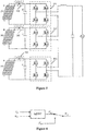
- a system structure of a current cascaded H-bridge inverter is as shown in Figure 1 .
- solar modules are connected in parallel with the direct current side of the cascaded H-bridge inverter, and transfer the energy in the direct current side to a power grid via the cascaded H-bridge inverter.
- a voltage across the solar panel will be significantly reduced, so that a voltage in the direct current side of the H-bridge inverter drops simultaneously, thereby affecting the normal operation of the system.
- the corresponding H-bridge module is generally bypassed, and the remaining H-bridge modules are configured for grid-connected power generation.
- the redundancy of the number of H-bridges cascaded in the overall system is insufficient, a total output modulation voltage of the cascaded H-bridge inverter will be reduced, and the system cannot operate stably, so that those intact solar panels are not be able to transfer energy to the power grid, thereby resulting in a significant loss of power generation.
- a cascaded H-bridge inverter and a method for handling a fault thereof are provided according to the present disclosure, to solve the problem of a loss of power generation caused by insufficient redundancy of the number of cascaded H-bridges.
- a method for handling a fault of a cascaded H-bridge inverter is provided according to the present disclosure, which is applied to a cascaded H-bridge inverter.
- the cascaded H-bridge inverter is connected to N solar panels.
- the cascaded H-bridge inverter includes N capacitors, N H-bridge modules, N switching devices and a controller, where N is a positive integer.
- the method includes detecting, by the controller, an output voltage or an output power of each of the N solar panels.
- the method further includes determining, by the controller, whether the output voltage of at least one of the N solar panels is lower than a preset voltage, or whether the output power of at least one of the N solar panels is lower than a preset power.
- the method further includes controlling a corresponding one of the N switching devices to be switched off and changing a set value of a voltage across a corresponding one of the N capacitors in the direct current side by the controller in a case that the output voltage of at least one of the N solar panels is lower than the preset voltage, or that the output power of at least one of the N solar panels is lower than the preset power.
- the method further includes controlling, by the controller, a corresponding one of the N H-bridge modules to perform inverting by taking the set value of the voltage across the capacitor in the direct current side as an input value, so that a total output modulation voltage of the cascaded H-bridge inverter meets a preset condition.
- the process of the controlling the corresponding switching device to be switched off and changing the set value of the voltage across the corresponding capacitor in the direct current side by the controller may include controlling, by the controller, the corresponding switching device to be switched off, and controlling, by the controller, the set value of the voltage across the corresponding capacitor in the direct current side to be raised.
- the method may further include determining, by the controller, whether the output voltage of at least one of the N solar panels is higher than the preset voltage, or whether the output power of at least one of the N solar panels is higher than the preset power, and controlling a corresponding one of the N H-bridge modules to perform inverting based on a Maximum Power Point Tracking (MPPT) control strategy and controlling a corresponding one of the N switching devices to be switched on by the controller in a case that the output voltage of at least one of the N solar panels is higher than the preset voltage, or that the output power of at least one of the N solar panels is higher than the preset power.
- MPPT Maximum Power Point Tracking
- the method may further include determining, by the controller, whether the cascaded H-bridge inverter is normally connected to the N solar panels, controlling, by the controller, the cascaded H-bridge inverter to enter into an operating state, in a case that the cascaded H-bridge inverter is normally connected to the N solar panels, and controlling, by the controller, the N switching devices to be switched on.
- a cascaded H-bridge inverter is provided according to the present disclosure.
- the cascaded H-bridge inverter is connected to N solar panels.
- the cascaded H-bridge inverter includes N capacitors, N H-bridge modules, N switching devices and a controller, where N is a positive integer.
- One output terminal of each of the N solar panels is connected to one input terminal of one of the N H-bridge modules via one of the N switching devices.
- the other output terminal of each of the N solar panels is connected to the other input terminal of one of the N H-bridge modules.
- Two input terminals of each of the N H-bridge modules are connected across a corresponding one of the N capacitors.
- Output terminals of the N H-bridge modules are connected in series.
- the controller is respectively connected to the N switching devices, the N capacitors and the N H-bridge modules.
- the controller is configured to detect an output voltage or an output power of each of the N solar panels, control a corresponding one of the N switching devices to be switched off and change a set value of a voltage across a one of the N capacitor sin the direct current side in a case that the output voltage of at least one of the N solar panels is lower than a preset voltage, or that the output power of at least one of the N solar panels is lower than a preset power.
- the controller is further configured to control a corresponding one of the N H-bridge modules to perform inverting by taking the set value of the voltage across the capacitor in the direct current side as an input value, so that a total output modulation voltage of the cascaded H-bridge inverter meets a preset condition.
- the controller may be configured to control the corresponding switching device to be switched off and changing the set value of the voltage across the corresponding capacitor in the direct current side by controlling the corresponding switching device to be switched off, and controlling the set value of the voltage across the corresponding capacitor in the direct current side to be raised.
- the controller may be further configured to control a corresponding one of the N H-bridge modules to perform inverting based on a maximum power point tracking (MPPT) control strategy and control a corresponding one of the N switching devices to be switched on, in a case that the output voltage of at least one of the N solar panels is higher than the preset voltage, or that the output power of at least one of the N solar panels is higher than the preset power.
- MPPT maximum power point tracking
- the controller may be further configured to determine whether the cascaded H-bridge inverter is normally connected to the N solar panels, control the cascaded H-bridge inverter to enter into an operating state, in a case that the cascaded H-bridge inverter is normally connected to the N solar panels, and control the N switching devices to be switched on after the cascaded H-bridge inverter enters into the operating state.
- each of the N switching devices may include a diode and a full control switch.
- An anode of the diode may be connected to a positive electrode of a corresponding one of the N solar panels, and a cathode of the diode may be connected to a corresponding one of the N capacitors and a corresponding one of the N H-bridge modules.
- a cathode of the diode may be connected to a negative electrode of a corresponding one of the N solar panels, and an anode of the diode may be connected to a corresponding one of the N capacitors and a corresponding one of the N H-bridge modules.
- the full control switch may be connected in parallel with the diode.
- the full control switch may be a relay or a semiconductor device.
- the output voltage or the output power of each of the N solar panels is detected by the controller.
- the controller controls the corresponding switching device to be switched off, and changes the set value of the voltage across the corresponding capacitor in the direct current side.
- the controller controls the corresponding H-bridge module to perform inverting by taking the set value of the voltage across the capacitor in the direct current side as the input value, so that the total output modulation voltage of the cascaded H-bridge inverter meets the preset condition, which avoids that the system cannot operate normally and stably and ensures that an intact solar panel can transfer energy to a power grid. Therefore, a significant loss of power generation is avoided.
- a method for handling a fault of a cascaded H-bridge inverter is provided according to the present disclosure, to solve the problem of a loss of power generation caused by insufficient redundancy of the number of cascaded H-bridges in the conventional art.
- the method for handling a fault of a cascaded H-bridge inverter is applied to a cascaded H-bridge inverter.
- the cascaded H-bridge inverter is connected to N solar panels.
- the cascaded H-bridge inverter includes N capacitors, N H-bridge modules, N switching devices and a controller, where N is a positive integer.
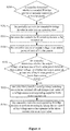
- the method for handling a fault of a cascaded H-bridge inverter is as shown in Figure 2 and includes steps S101 to S104.
- step S101 the controller detects an output voltage or an output power of each of the N solar panels.
- the controller controls the N H-bridge modules to perform inverting based on a maximum power point tracking (MPPT) control strategy based on the output voltage or the output power.
- MPPT maximum power point tracking
- step S102 the controller determines whether the output voltage of at least one of the N solar panels is lower than a preset voltage, or whether the output power of at least one of the N solar panels is lower than a preset power.
- step S103 in a case that the output voltage of at least one of the N solar panels is lower than the preset voltage, or that the output power of at least one of the N solar panels is lower than the preset power, the controller controls a corresponding switching device to be switched off and changes a set value of a voltage across a corresponding capacitor in the direct current side, which equivalently bypasses the solar panel which is seriously blocked or fails to work, thus, the solar panel cannot output a voltage to the corresponding H-bridge module.
- the controller changes the set value of the voltage across the corresponding capacitor in the direct current side.
- the set value of the voltage across the capacitor in the direct current side is preferably higher than the output voltage of the solar panel.
- step S104 the controller controls a corresponding H-bridge module to perform inverting by taking the set value of the voltage across the capacitor in the direct current side as an input value, so that a total output modulation voltage of the cascaded H-bridge inverter meets a preset condition.
- the corresponding H-bridge module performs inverting by taking the set value of the voltage across the capacitor in the direct current side as the input value, so that it is ensured that the corresponding H-bridge module can provide a certain output voltage in a case that the solar panel is seriously blocked or fails to work, and thus that the total output modulation voltage of the cascaded H-bridge inverter meets the preset condition of grid-connected power generation of the cascaded H-bridge inverter, thereby ensuring that the cascaded H-bridge inverter operates stably.
- the controller controls the corresponding switching device to be switched off, and changes the set value of the voltage across the capacitor in the direct current side.
- the controller controls the corresponding H-bridge module to perform inverting by taking the set value of the voltage across the capacitor in the direct current side as the input value, so that the total output modulation voltage of the cascaded H-bridge inverter meets the preset condition of grid-connected power generation of the cascaded H-bridge inverter, which avoids that the system cannot operate normally and stably and ensures that an intact solar panel can transfer energy to a power grid. Therefore, a significant loss of power generation is avoided.
- step S103 includes controlling, by the controller, the corresponding switching device to be switched off, and controlling, by the controller, the set value of the voltage across the corresponding capacitor in the direct current side to be raised.
- the controller may compute the set value of the voltage across the corresponding capacitor in the direct current side, based on the total output modulation voltage needed by the cascaded H-bridge inverter to meet the preset condition.
- the controller controls the corresponding H-bridge module to perform inverting by taking the raised set value of the voltage across the capacitor (greater than the output voltage of the solar panel) as the input value, to make the total output modulation voltage of the cascaded H-bridge inverter meet the preset condition of grid-connected power generation of the cascaded H-bridge inverter.
- the method further includes steps S105 and S106.
- step S105 the controller determines whether the output voltage of at least one of the N solar panels is higher than the preset voltage, or whether the output power of at least one of the N solar panels is higher than the preset power.
- step S106 in a case that the output voltage of at least one of the N solar panels is higher than the preset voltage, or that the output power of at least one of the N solar panels is higher than the preset power, the controller controls a corresponding H-bridge module to perform inverting based on a maximum power point tracking (MPPT) control strategy and controls a corresponding switching device to be switched on.
- MPPT maximum power point tracking
- the controller determines the detected output voltage and output power of each of the N solar panels. In a case that the output voltage of at least one of the N solar panels is higher than the preset voltage, or that the output power of at least one of the N solar panels is higher than the preset power, it indicates that the equivalently bypassed solar panel restores to the normal operating state and can provide the output voltage meeting the requirement.
- the controller may control the corresponding H-bridge module to restore to the normal operating state in which the H-bridge module performs inverting based on the MPPT control strategy, and the controller may control the corresponding switching device to be switched on.
- the method further includes steps S201 to S203.
- step S201 the controller determines whether the cascaded H-bridge inverter is normally connected to the N solar panels.
- step S202 in a case that the cascaded H-bridge inverter is normally connected to the N solar panels, the controller controls the cascaded H-bridge inverter to enter into an operating state.
- step S203 after the cascaded H-bridge inverter enters into the operating state, the controller controls the N switching devices to be switched on.
- step S203 is performed before step S101.
- Figure 4 is merely an example, and step S203 may be performed in other order, as long as step S203 is performed before step S103, which is not specifically limited herein, all of which is within the scope of the present application.
- each of the N switching devices includes a diode and a full control switch.
- An anode of the diode is connected to a positive electrode of a corresponding solar panel, and a cathode of the diode is connected to a corresponding capacitor and a corresponding H-bridge module.
- the cathode of the diode is connected to a negative electrode of a corresponding solar panel, and the anode of the diode is connected to a corresponding capacitor and a corresponding H-bridge module.
- the full control switch is connected in parallel with the diode.
- the full control switch is a relay or a semiconductor device.
- the switching device includes the diode and the full control switch.
- the diode may play a role of anti-reverse connection.
- the controller controls the N switching devices to be switched on, and may bypass the diode to reduce a voltage drop loss of the diode in an on-state.
- the controller controls the full control switch in the corresponding switching device to be switched off, and changes the set value of the voltage across the corresponding capacitor in the direct current side, to ensure that the cascaded H-bridge inverter operates stably.
- the set value of the voltage across the capacitor in the direct current side is higher than the output voltage of the solar panel. In this case, the diode is switched off in a reverse direction, so that the solar panel is equivalently bypassed.
- a cascaded H-bridge inverter is further provided according to another embodiment of the present disclosure.
- the cascaded H-bridge inverter is connected to N solar panels PV.
- the cascaded H-bridge inverter includes N capacitors C, N H-bridge modules 101, N switching devices 102 and a controller, where N is a positive integer.
- One output terminal of each of the solar panels PV is connected to one input terminal of one of the H-bridge modules 101 via one of the switching devices 102.
- the other output terminal of each of the solar panels PV is connected to the other input terminal of one of the H-bridge modules 101.
- Two input terminals of each of the H-bridge modules 101 are connected across a corresponding capacitor.
- Output terminals of the N H-bridge modules 101 are connected in series.
- the controller is respectively connected to the N switching devices 102, the N capacitors C and the N H-bridge modules101.
- the switching device 102 is connected between a positive electrode of the solar panel PV and the H-bridge module 101.
- the switching device 102 may be connected between a negative electrode of the solar panel PV and the H-bridge module 101, and in this case, an installation direction of the switching device 102 is reversed as compared with that shown in Figure 5 , both of which are within the scope of the present application, and which is not specifically limited herein.
- the controller detects an output voltage or an output power of each of the N solar panels PV. In a case that the output voltage of at least one of the N solar panels is lower than a preset voltage, or that the output power of at least one of the N solar panels is lower than a preset power, the controller controls a corresponding switching device 102 to be switched off, and changes a set value of a voltage across a corresponding capacitor in the direct current side.
- the controller controls a corresponding H-bridge module 101 to perform inverting by taking the set value of the voltage across the capacitor in the direct current side as an input value, so that a total output modulation voltage of the cascaded H-bridge inverter meets a preset condition of grid-connected power generation of the cascaded H-bridge inverter.
- the controller controls the corresponding switching device 102 to be switched off, and changes the set value of the voltage across the corresponding capacitor in the direct current side.
- the controller controls the corresponding H-bridge module 101 to perform inverting by taking the set value of the voltage across the capacitor in the direct current side as the input value, so that the total output modulation voltage of the cascaded H-bridge inverter meets the preset condition of grid-connected power generation of the cascaded H-bridge inverter, which avoids that the system cannot operate normally and stably and ensures that an intact solar panel can transfer energy to a power grid. Therefore, a significant loss of power generation is avoided.
- the controller is configured to control the corresponding switching device to be switched off and changing the set value of the voltage across the corresponding capacitor in the direct current side by controlling the corresponding switching device to be switched off, and controlling the set value of the voltage across the corresponding capacitor in the direct current side to be raised.
- the controller is further configured to control a corresponding H-bridge module to perform inverting based on a maximum power point tracking (MPPT) control strategy and control a corresponding switching device to be switched on, in a case that the output voltage of at least one of the solar panels is higher than the preset voltage, or that the output power of at least one of the solar panels is higher than the preset power.
- MPPT maximum power point tracking
- each of the N H-bridge modules 101 performs inverting by taking, as an input value Vdc, a direct current voltage Vdc1 outputted based on the MPPT control strategy based on an output voltage Vpv and an output current Ipv of the respective solar panel PV.
- the corresponding H-bridge module 101 perform inverting by taking the set value of the voltage Vdc2 across the capacitor in the direct current side as the input value Vdc, so that the total output modulation voltage of the cascaded H-bridge inverter meets the preset condition.
- the controller may control the corresponding H-bridge module 101 to restore to the normal operating state in which the H-bridge module 101 performs inverting based on the MPPT control strategy, and the controller may control the corresponding switching device 102 to be switched on.
- the controller is further configured to determine whether the cascaded H-bridge inverter is normally connected to the N solar panels PV.
- the controller is further configured to control the cascaded H-bridge inverter to enter into an operating state in a case that the cascaded H-bridge inverter is normally connected to the N solar panels PV, and control the N switching devices 102 to be switched on after the cascaded H-bridge inverter enters into the operating state.
- each of the switching devices 102 includes a diode and a full control switch.
- An anode of the diode is connected to a positive electrode of the corresponding solar panel, and a cathode of the diode is connected to the corresponding capacitor and the corresponding H-bridge module, as shown in Figure 5 .
- the cathode of the diode is connected to a negative electrode of the corresponding solar panel, and the anode of the diode is connected to the corresponding capacitor and the corresponding H-bridge module.
- the full control switch is connected in parallel with the diode.
- a connection direction of the diode is an installation direction of the switching device.
- the switching device is connected between the positive electrode of the solar panel and the H-bridge module.
- the cathode of the diode is connected to the negative electrode of the corresponding solar panel
- the anode of the diode is connected to the corresponding capacitor and the corresponding H-bridge module, both of which are within the scope of the present application, with the implementation being determined according to the specific application environment.
- the full control switch is a relay or a semiconductor device.
- the present disclosure can be implemented or used by those skilled in the art.
- Various modifications made to these embodiments may be obvious for those skilled in the art, and a normal principle defined in the present disclosure may be implemented in other embodiments without departing from the spirit or scope of the present disclosure. Therefore, the present disclosure is not limited to the embodiments described herein but confirms to a widest scope in accordance with principles and novel features disclosed in the present disclosure.
Landscapes
- Engineering & Computer Science (AREA)
- Power Engineering (AREA)
- Inverter Devices (AREA)
- Control Of Electrical Variables (AREA)
Abstract
Description
- The present disclosure relates to the technical field of power electronics, and in particular to a cascaded H-bridge inverter and a method for handling a fault thereof.
- In recent years, the cascaded multi-level topology has been widely used by virtue of its excellent performance. Among all cascaded multi-level topologies, the cascaded H-bridge topology is favored due to its modular structure, simple layout, few components required to achieve the same number of levels and high system reliability.
- A system structure of a current cascaded H-bridge inverter is as shown in
Figure 1 . In a normal operation, solar modules are connected in parallel with the direct current side of the cascaded H-bridge inverter, and transfer the energy in the direct current side to a power grid via the cascaded H-bridge inverter. However, when a solar panel is seriously blocked or fails to work, a voltage across the solar panel will be significantly reduced, so that a voltage in the direct current side of the H-bridge inverter drops simultaneously, thereby affecting the normal operation of the system. - In the conventional technology, the corresponding H-bridge module is generally bypassed, and the remaining H-bridge modules are configured for grid-connected power generation. However, if the redundancy of the number of H-bridges cascaded in the overall system is insufficient, a total output modulation voltage of the cascaded H-bridge inverter will be reduced, and the system cannot operate stably, so that those intact solar panels are not be able to transfer energy to the power grid, thereby resulting in a significant loss of power generation.
- In view of the above, a cascaded H-bridge inverter and a method for handling a fault thereof are provided according to the present disclosure, to solve the problem of a loss of power generation caused by insufficient redundancy of the number of cascaded H-bridges.
- To achieve the object, the technical solutions of the present disclosure are provided in the following.
- A method for handling a fault of a cascaded H-bridge inverter is provided according to the present disclosure, which is applied to a cascaded H-bridge inverter. The cascaded H-bridge inverter is connected to N solar panels. The cascaded H-bridge inverter includes N capacitors, N H-bridge modules, N switching devices and a controller, where N is a positive integer. The method includes detecting, by the controller, an output voltage or an output power of each of the N solar panels. The method further includes determining, by the controller, whether the output voltage of at least one of the N solar panels is lower than a preset voltage, or whether the output power of at least one of the N solar panels is lower than a preset power. The method further includes controlling a corresponding one of the N switching devices to be switched off and changing a set value of a voltage across a corresponding one of the N capacitors in the direct current side by the controller in a case that the output voltage of at least one of the N solar panels is lower than the preset voltage, or that the output power of at least one of the N solar panels is lower than the preset power. The method further includes controlling, by the controller, a corresponding one of the N H-bridge modules to perform inverting by taking the set value of the voltage across the capacitor in the direct current side as an input value, so that a total output modulation voltage of the cascaded H-bridge inverter meets a preset condition.
- Preferably, the process of the controlling the corresponding switching device to be switched off and changing the set value of the voltage across the corresponding capacitor in the direct current side by the controller may include controlling, by the controller, the corresponding switching device to be switched off, and controlling, by the controller, the set value of the voltage across the corresponding capacitor in the direct current side to be raised.
- Preferably, after the process of the controlling, by the controller, the corresponding H-bridge module to perform inverting by taking the set value of the voltage across the capacitor in the direct current side as the input value, the method may further include determining, by the controller, whether the output voltage of at least one of the N solar panels is higher than the preset voltage, or whether the output power of at least one of the N solar panels is higher than the preset power, and controlling a corresponding one of the N H-bridge modules to perform inverting based on a Maximum Power Point Tracking (MPPT) control strategy and controlling a corresponding one of the N switching devices to be switched on by the controller in a case that the output voltage of at least one of the N solar panels is higher than the preset voltage, or that the output power of at least one of the N solar panels is higher than the preset power.
- Preferably, before the process of the controlling the corresponding switching device to be switched off and changing the set value of the voltage across the corresponding capacitor in the direct current side by the controller, the method may further include determining, by the controller, whether the cascaded H-bridge inverter is normally connected to the N solar panels, controlling, by the controller, the cascaded H-bridge inverter to enter into an operating state, in a case that the cascaded H-bridge inverter is normally connected to the N solar panels, and controlling, by the controller, the N switching devices to be switched on.
- A cascaded H-bridge inverter is provided according to the present disclosure. The cascaded H-bridge inverter is connected to N solar panels. The cascaded H-bridge inverter includes N capacitors, N H-bridge modules, N switching devices and a controller, where N is a positive integer. One output terminal of each of the N solar panels is connected to one input terminal of one of the N H-bridge modules via one of the N switching devices. The other output terminal of each of the N solar panels is connected to the other input terminal of one of the N H-bridge modules. Two input terminals of each of the N H-bridge modules are connected across a corresponding one of the N capacitors. Output terminals of the N H-bridge modules are connected in series. The controller is respectively connected to the N switching devices, the N capacitors and the N H-bridge modules. The controller is configured to detect an output voltage or an output power of each of the N solar panels, control a corresponding one of the N switching devices to be switched off and change a set value of a voltage across a one of the N capacitor sin the direct current side in a case that the output voltage of at least one of the N solar panels is lower than a preset voltage, or that the output power of at least one of the N solar panels is lower than a preset power. The controller is further configured to control a corresponding one of the N H-bridge modules to perform inverting by taking the set value of the voltage across the capacitor in the direct current side as an input value, so that a total output modulation voltage of the cascaded H-bridge inverter meets a preset condition.
- Preferably, the controller may be configured to control the corresponding switching device to be switched off and changing the set value of the voltage across the corresponding capacitor in the direct current side by controlling the corresponding switching device to be switched off, and controlling the set value of the voltage across the corresponding capacitor in the direct current side to be raised.
- Preferably, the controller may be further configured to control a corresponding one of the N H-bridge modules to perform inverting based on a maximum power point tracking (MPPT) control strategy and control a corresponding one of the N switching devices to be switched on, in a case that the output voltage of at least one of the N solar panels is higher than the preset voltage, or that the output power of at least one of the N solar panels is higher than the preset power.
- Preferably, the controller may be further configured to determine whether the cascaded H-bridge inverter is normally connected to the N solar panels, control the cascaded H-bridge inverter to enter into an operating state, in a case that the cascaded H-bridge inverter is normally connected to the N solar panels, and control the N switching devices to be switched on after the cascaded H-bridge inverter enters into the operating state.
- Preferably, each of the N switching devices may include a diode and a full control switch. An anode of the diode may be connected to a positive electrode of a corresponding one of the N solar panels, and a cathode of the diode may be connected to a corresponding one of the N capacitors and a corresponding one of the N H-bridge modules. Alternatively, a cathode of the diode may be connected to a negative electrode of a corresponding one of the N solar panels, and an anode of the diode may be connected to a corresponding one of the N capacitors and a corresponding one of the N H-bridge modules. The full control switch may be connected in parallel with the diode.
- Preferably, the full control switch may be a relay or a semiconductor device.
- Based on the method for handling a fault of a cascaded H-bridge inverter according to the present disclosure, the output voltage or the output power of each of the N solar panels is detected by the controller. In a case that the output voltage of at least one of the N solar panels is lower than the preset voltage, or that the output power of at least one of the N solar panels is lower than the preset power, the controller controls the corresponding switching device to be switched off, and changes the set value of the voltage across the corresponding capacitor in the direct current side. Then, the controller controls the corresponding H-bridge module to perform inverting by taking the set value of the voltage across the capacitor in the direct current side as the input value, so that the total output modulation voltage of the cascaded H-bridge inverter meets the preset condition, which avoids that the system cannot operate normally and stably and ensures that an intact solar panel can transfer energy to a power grid. Therefore, a significant loss of power generation is avoided.
- To illustrate technical solutions according to embodiments of the present disclosure or in the conventional technologies more clearly, drawings to be used in the descriptions of the embodiments or the conventional technologies are described briefly hereinafter. Apparently, the drawings described hereinafter are only for some embodiments of the present disclosure, and other drawings may be obtained by those skilled in the art based on those drawings without creative efforts.
-
Figure 1 is a schematic structural diagram of a conventional cascaded H-bridge inverter; -
Figure 2 is a flow chart of a method for handling a fault of a cascaded H-bridge inverter according to an embodiment of the present disclosure; -
Figure 3 is a flow chart of a method for handling a fault of a cascaded H-bridge inverter according to another embodiment of the present disclosure; -
Figure 4 is a flow chart of a method for handling a fault of a cascaded H-bridge inverter according to another embodiment of the present disclosure; -
Figure 5 is a schematic structural diagram of a cascaded H-bridge inverter according to an embodiment of the present disclosure; and -
Figure 6 is a schematic diagram of a control strategy of an H-bridge module according to an embodiment of the present disclosure. - Technical solutions of the embodiments of the present disclosure are illustrated clearly and completely in conjunction with drawings of the embodiments of the present disclosure. Apparently, the described embodiments are merely a few rather than all of the embodiments of the present disclosure. All other embodiments obtained by those skilled in the art based on the embodiments of the present disclosure without creative efforts shall fall within the protection scope of the present disclosure.
- A method for handling a fault of a cascaded H-bridge inverter is provided according to the present disclosure, to solve the problem of a loss of power generation caused by insufficient redundancy of the number of cascaded H-bridges in the conventional art.
- Specifically, the method for handling a fault of a cascaded H-bridge inverter is applied to a cascaded H-bridge inverter. The cascaded H-bridge inverter is connected to N solar panels. The cascaded H-bridge inverter includes N capacitors, N H-bridge modules, N switching devices and a controller, where N is a positive integer. The method for handling a fault of a cascaded H-bridge inverter is as shown in
Figure 2 and includes steps S101 to S104. - In step S101, the controller detects an output voltage or an output power of each of the N solar panels.
- When the cascaded H-bridge inverter is in a normal operating state, the controller controls the N H-bridge modules to perform inverting based on a maximum power point tracking (MPPT) control strategy based on the output voltage or the output power. When one of the N solar panels is seriously blocked or fails to work, the output voltage and the output power of the solar panel will be significantly reduced, so that a voltage in the direct current side of the corresponding H-bridge inverter drops simultaneously, thereby affecting the normal operation of the system.
- In step S102, the controller determines whether the output voltage of at least one of the N solar panels is lower than a preset voltage, or whether the output power of at least one of the N solar panels is lower than a preset power.
- In step S103, in a case that the output voltage of at least one of the N solar panels is lower than the preset voltage, or that the output power of at least one of the N solar panels is lower than the preset power, the controller controls a corresponding switching device to be switched off and changes a set value of a voltage across a corresponding capacitor in the direct current side, which equivalently bypasses the solar panel which is seriously blocked or fails to work, thus, the solar panel cannot output a voltage to the corresponding H-bridge module. In this case, the controller changes the set value of the voltage across the corresponding capacitor in the direct current side. To ensure the cascaded H-bridge inverter to operate stably, the set value of the voltage across the capacitor in the direct current side is preferably higher than the output voltage of the solar panel.
- In step S104, the controller controls a corresponding H-bridge module to perform inverting by taking the set value of the voltage across the capacitor in the direct current side as an input value, so that a total output modulation voltage of the cascaded H-bridge inverter meets a preset condition.
- The corresponding H-bridge module performs inverting by taking the set value of the voltage across the capacitor in the direct current side as the input value, so that it is ensured that the corresponding H-bridge module can provide a certain output voltage in a case that the solar panel is seriously blocked or fails to work, and thus that the total output modulation voltage of the cascaded H-bridge inverter meets the preset condition of grid-connected power generation of the cascaded H-bridge inverter, thereby ensuring that the cascaded H-bridge inverter operates stably.
- Based on the method for handling a fault of a cascaded H-bridge inverter according to the embodiment, in a case that the output voltage of at least one of the N solar panels is lower than the preset voltage, or that the output power of at least one of the N solar panels is lower than the preset power, the controller controls the corresponding switching device to be switched off, and changes the set value of the voltage across the capacitor in the direct current side. Then, the controller controls the corresponding H-bridge module to perform inverting by taking the set value of the voltage across the capacitor in the direct current side as the input value, so that the total output modulation voltage of the cascaded H-bridge inverter meets the preset condition of grid-connected power generation of the cascaded H-bridge inverter, which avoids that the system cannot operate normally and stably and ensures that an intact solar panel can transfer energy to a power grid. Therefore, a significant loss of power generation is avoided.
- Preferably, step S103 includes controlling, by the controller, the corresponding switching device to be switched off, and controlling, by the controller, the set value of the voltage across the corresponding capacitor in the direct current side to be raised.
- In a case that the output voltage of at least one of the N solar panels is lower than the preset voltage, or that the output power of at least one of the N solar panels is lower than the preset power, the controller may compute the set value of the voltage across the corresponding capacitor in the direct current side, based on the total output modulation voltage needed by the cascaded H-bridge inverter to meet the preset condition. The controller controls the corresponding H-bridge module to perform inverting by taking the raised set value of the voltage across the capacitor (greater than the output voltage of the solar panel) as the input value, to make the total output modulation voltage of the cascaded H-bridge inverter meet the preset condition of grid-connected power generation of the cascaded H-bridge inverter.
- Preferably, as shown in
Figure 3 , after step S104, the method further includes steps S105 and S106. - In step S105, the controller determines whether the output voltage of at least one of the N solar panels is higher than the preset voltage, or whether the output power of at least one of the N solar panels is higher than the preset power.
- In step S106, in a case that the output voltage of at least one of the N solar panels is higher than the preset voltage, or that the output power of at least one of the N solar panels is higher than the preset power, the controller controls a corresponding H-bridge module to perform inverting based on a maximum power point tracking (MPPT) control strategy and controls a corresponding switching device to be switched on.
- To make the total output modulation voltage of the cascaded H-bridge inverter meet the preset condition, the solar panel which is seriously blocked or fails to work is equivalently bypassed, and the corresponding H-bridge module performs inverting by taking the set value of the voltage across the capacitor in the direct current side as the input value. The controller determines the detected output voltage and output power of each of the N solar panels. In a case that the output voltage of at least one of the N solar panels is higher than the preset voltage, or that the output power of at least one of the N solar panels is higher than the preset power, it indicates that the equivalently bypassed solar panel restores to the normal operating state and can provide the output voltage meeting the requirement. In this case, the controller may control the corresponding H-bridge module to restore to the normal operating state in which the H-bridge module performs inverting based on the MPPT control strategy, and the controller may control the corresponding switching device to be switched on.
- Preferably, as shown in
Figure 4 , before step S103, the method further includes steps S201 to S203. - In step S201, the controller determines whether the cascaded H-bridge inverter is normally connected to the N solar panels.
- In step S202, in a case that the cascaded H-bridge inverter is normally connected to the N solar panels, the controller controls the cascaded H-bridge inverter to enter into an operating state.
- In step S203, after the cascaded H-bridge inverter enters into the operating state, the controller controls the N switching devices to be switched on.
- As shown in
Figure 4 , step S203 is performed before step S101. However,Figure 4 is merely an example, and step S203 may be performed in other order, as long as step S203 is performed before step S103, which is not specifically limited herein, all of which is within the scope of the present application. - Preferably, each of the N switching devices includes a diode and a full control switch. An anode of the diode is connected to a positive electrode of a corresponding solar panel, and a cathode of the diode is connected to a corresponding capacitor and a corresponding H-bridge module. Alternatively, the cathode of the diode is connected to a negative electrode of a corresponding solar panel, and the anode of the diode is connected to a corresponding capacitor and a corresponding H-bridge module. The full control switch is connected in parallel with the diode.
- Preferably, the full control switch is a relay or a semiconductor device.
- The switching device includes the diode and the full control switch. In a case that controller determines that the cascaded H-bridge inverter is normally connected to the N solar panels, the diode may play a role of anti-reverse connection.
- After controlling the cascaded H-bridge inverter to enter into the operating state, the controller controls the N switching devices to be switched on, and may bypass the diode to reduce a voltage drop loss of the diode in an on-state.
- In a case that the output voltage of at least one of the N solar panels is lower than the preset voltage, or that the output power of at least one of the N solar panels is lower than the preset power, the controller controls the full control switch in the corresponding switching device to be switched off, and changes the set value of the voltage across the corresponding capacitor in the direct current side, to ensure that the cascaded H-bridge inverter operates stably. Preferably, the set value of the voltage across the capacitor in the direct current side is higher than the output voltage of the solar panel. In this case, the diode is switched off in a reverse direction, so that the solar panel is equivalently bypassed.
- A cascaded H-bridge inverter is further provided according to another embodiment of the present disclosure. As shown in
Figure 5 , the cascaded H-bridge inverter is connected to N solar panels PV. The cascaded H-bridge inverter includes N capacitors C, N H-bridge modules 101,N switching devices 102 and a controller, where N is a positive integer. One output terminal of each of the solar panels PV is connected to one input terminal of one of the H-bridge modules 101 via one of theswitching devices 102. The other output terminal of each of the solar panels PV is connected to the other input terminal of one of the H-bridge modules 101. Two input terminals of each of the H-bridge modules 101 are connected across a corresponding capacitor. Output terminals of the N H-bridge modules 101 are connected in series. The controller is respectively connected to theN switching devices 102, the N capacitors C and the N H-bridge modules101. - As shown in
Figure 5 , by way of example, theswitching device 102 is connected between a positive electrode of the solar panel PV and the H-bridge module 101. Alternatively, theswitching device 102 may be connected between a negative electrode of the solar panel PV and the H-bridge module 101, and in this case, an installation direction of theswitching device 102 is reversed as compared with that shown inFigure 5 , both of which are within the scope of the present application, and which is not specifically limited herein. - The detailed operating principles are described below.
- The controller detects an output voltage or an output power of each of the N solar panels PV. In a case that the output voltage of at least one of the N solar panels is lower than a preset voltage, or that the output power of at least one of the N solar panels is lower than a preset power, the controller controls a
corresponding switching device 102 to be switched off, and changes a set value of a voltage across a corresponding capacitor in the direct current side. The controller controls a corresponding H-bridge module 101 to perform inverting by taking the set value of the voltage across the capacitor in the direct current side as an input value, so that a total output modulation voltage of the cascaded H-bridge inverter meets a preset condition of grid-connected power generation of the cascaded H-bridge inverter. - Based on the cascaded H-bridge inverter according to the embodiment, in a case that the output voltage of at least one of the N solar panels is lower than the preset voltage, or that the output power of at least one of the N solar panels is lower than the preset power, the controller controls the
corresponding switching device 102 to be switched off, and changes the set value of the voltage across the corresponding capacitor in the direct current side. Then, the controller controls the corresponding H-bridge module 101 to perform inverting by taking the set value of the voltage across the capacitor in the direct current side as the input value, so that the total output modulation voltage of the cascaded H-bridge inverter meets the preset condition of grid-connected power generation of the cascaded H-bridge inverter, which avoids that the system cannot operate normally and stably and ensures that an intact solar panel can transfer energy to a power grid. Therefore, a significant loss of power generation is avoided. - Preferably, the controller is configured to control the corresponding switching device to be switched off and changing the set value of the voltage across the corresponding capacitor in the direct current side by controlling the corresponding switching device to be switched off, and controlling the set value of the voltage across the corresponding capacitor in the direct current side to be raised.
- Preferably, the controller is further configured to control a corresponding H-bridge module to perform inverting based on a maximum power point tracking (MPPT) control strategy and control a corresponding switching device to be switched on, in a case that the output voltage of at least one of the solar panels is higher than the preset voltage, or that the output power of at least one of the solar panels is higher than the preset power.
- The control strategy used by the N H-
bridge modules 101 to perform inverting is as shown inFigure 6 . In a normal operating state, each of the N H-bridge modules 101 performs inverting by taking, as an input value Vdc, a direct current voltage Vdc1 outputted based on the MPPT control strategy based on an output voltage Vpv and an output current Ipv of the respective solar panel PV. - In a case that the output voltage of at least one of the N solar panels is lower than the preset voltage, or that the output power of at least one of the N solar panels is lower than the preset power, the corresponding H-
bridge module 101 perform inverting by taking the set value of the voltage Vdc2 across the capacitor in the direct current side as the input value Vdc, so that the total output modulation voltage of the cascaded H-bridge inverter meets the preset condition. - In a case that the equivalently bypassed solar panel PV restores to the normal operating state and can provide the output voltage meeting the requirement, the controller may control the corresponding H-
bridge module 101 to restore to the normal operating state in which the H-bridge module 101 performs inverting based on the MPPT control strategy, and the controller may control thecorresponding switching device 102 to be switched on. - Preferably, the controller is further configured to determine whether the cascaded H-bridge inverter is normally connected to the N solar panels PV. The controller is further configured to control the cascaded H-bridge inverter to enter into an operating state in a case that the cascaded H-bridge inverter is normally connected to the N solar panels PV, and control the
N switching devices 102 to be switched on after the cascaded H-bridge inverter enters into the operating state. - Preferably, as shown in
Figure 5 , each of theswitching devices 102 includes a diode and a full control switch. An anode of the diode is connected to a positive electrode of the corresponding solar panel, and a cathode of the diode is connected to the corresponding capacitor and the corresponding H-bridge module, as shown inFigure 5 . Alternatively, the cathode of the diode is connected to a negative electrode of the corresponding solar panel, and the anode of the diode is connected to the corresponding capacitor and the corresponding H-bridge module. The full control switch is connected in parallel with the diode. - A connection direction of the diode is an installation direction of the switching device. As shown in
Figure 5 , the switching device is connected between the positive electrode of the solar panel and the H-bridge module. In a case that the switching device is connected between the negative electrode of the solar panel PV and the H-bridge module 101, the cathode of the diode is connected to the negative electrode of the corresponding solar panel, and the anode of the diode is connected to the corresponding capacitor and the corresponding H-bridge module, both of which are within the scope of the present application, with the implementation being determined according to the specific application environment. - Preferably, the full control switch is a relay or a semiconductor device.
- The detailed operating principles of this embodiment are similar to the above embodiments, which are not repeated herein.
- The embodiments of the present disclosure are described in a progressive manner and each embodiment places emphasis on the difference from other embodiments. Therefore, one embodiment can refer to other embodiments for the same or similar parts. Since the device according to the embodiment corresponds to the method disclosed in the embodiments, the description of the device is simple, and correlation parts can refer to the parts of the method.
- According to the description of the disclosed embodiments, the present disclosure can be implemented or used by those skilled in the art. Various modifications made to these embodiments may be obvious for those skilled in the art, and a normal principle defined in the present disclosure may be implemented in other embodiments without departing from the spirit or scope of the present disclosure. Therefore, the present disclosure is not limited to the embodiments described herein but confirms to a widest scope in accordance with principles and novel features disclosed in the present disclosure.
Claims (10)
- A method for handling a fault of a cascaded H-bridge inverter, comprising:in the cascaded H-bridge inverter connected to N solar panels and comprising N capacitors, N H-bridge modules, N switching devices and a controller, with N being a positive integer,detecting, by the controller, an output voltage or an output power of each of the N solar panels;determining, by the controller, whether the output voltage of at least one of the N solar panels is lower than a preset voltage, or whether the output power of at least one of the N solar panels is lower than a preset power;controlling a corresponding one of the N switching devices to be switched off and changing a set value of a voltage across a corresponding one of the N capacitors in the direct current side by the controller, in a case that the output voltage of at least one of the N solar panels is lower than the preset voltage, or that the output power of at least one of the N solar panels is lower than the preset power; andcontrolling, by the controller, a corresponding one of the N H-bridge modules to perform inverting by taking the set value of the voltage across the capacitor in the direct current side as an input value, so that a total output modulation voltage of the cascaded H-bridge inverter meets a preset condition.
- The method according to claim 1, wherein the process of the controlling the corresponding switching device to be switched off and changing the set value of the voltage across the corresponding capacitor in the direct current side by the controller comprises:controlling, by the controller, the corresponding switching device to be switched off; andcontrolling, by the controller, the set value of the voltage across the corresponding capacitor in the direct current side to be raised.
- The method according to claim 1, wherein after the process of the controlling, by the controller, the corresponding H-bridge module to perform inverting by taking the set value of the voltage across the capacitor in the direct current side as the input value, the method further comprises:determining, by the controller, whether the output voltage of at least one of the N solar panels is higher than the preset voltage, or whether the output power of at least one of the N solar panels is higher than the preset power; andcontrolling a corresponding one of the N H-bridge modules to perform inverting based on a maximum power point tracking control strategy and controlling a corresponding one of the N switching devices to be switched on by the controller, in a case that the output voltage of at least one of the N solar panels is higher than the preset voltage, or that the output power of at least one of the N solar panels is higher than the preset power.
- The method according to any one of claims 1 to 3, wherein before the process of the controlling the corresponding switching device to be switched off and changing the set value of the voltage across the corresponding capacitor in the direct current side by the controller, the method further comprises:determining, by the controller, whether the cascaded H-bridge inverter is normally connected to the N solar panels;controlling, by the controller, the cascaded H-bridge inverter to enter into an operating state, in a case that the cascaded H-bridge inverter is normally connected to the N solar panels; andcontrolling, by the controller, the N switching devices to be switched on.
- A cascaded H-bridge inverter, connected to N solar panels and comprising N capacitors, N H-bridge modules, N switching devices and a controller, with N being a positive integer, wherein
one output terminal of each of the N solar panels is connected to one input terminal of one of the N H-bridge modules via one of the N switching devices;
the other output terminal of each of the N solar panels is connected to the other input terminal of one of the N H-bridge modules;
two input terminals of each of the N H-bridge modules are connected across a corresponding one of the N capacitors;
output terminals of the N H-bridge modules are connected in series; and
the controller is respectively connected to the N switching devices, the N capacitors and the N H-bridge modules, and the controller is configured to detect an output voltage or an output power of each of the N solar panels, control a corresponding one of the N switching devices to be switched off and change a set value of a voltage across a corresponding one of the N capacitors in the direct current side in a case that the output voltage of at least one of the N solar panels is lower than a preset voltage, or that the output power of at least one of the N solar panels is lower than a preset power, and control a corresponding one of the N H-bridge modules to perform inverting by taking the set value of the voltage across the capacitor in the direct current side as an input value, so that a total output modulation voltage of the cascaded H-bridge inverter meets a preset condition. - The cascaded H-bridge inverter according to claim 5, wherein the controller is configured to control the corresponding switching device to be switched off and changing the set value of the voltage across the corresponding capacitor in the direct current side by
controlling the corresponding switching device to be switched off; and
controlling the set value of the voltage across the corresponding capacitor in the direct current side to be raised. - The cascaded H-bridge inverter according to claim 5, wherein the controller is further configured to control a corresponding one of the N H-bridge modules to perform inverting based on a maximum power point tracking control strategy and control a corresponding one of the N switching devices to be switched on, in a case that the output voltage of at least one of the N solar panels is higher than the preset voltage, or that the output power of at least one of the N solar panels is higher than the preset power.
- The cascaded H-bridge inverter according to claim 5, wherein the controller is further configured to determine whether the cascaded H-bridge inverter is normally connected to the N solar panels, control the cascaded H-bridge inverter to enter into an operating state in a case that the cascaded H-bridge inverter is normally connected to the N solar panels, and control the N switching devices to be switched on after the cascaded H-bridge inverter enters into the operating state.
- The cascaded H-bridge inverter according to any one of claims 5 to 8, wherein each of the N switching devices comprises a diode and a full control switch,
an anode of the diode is connected to a positive electrode of a corresponding one of the N solar panels, and a cathode of the diode is connected to a corresponding one of the N capacitors and a corresponding one of the N H-bridge modules; or
a cathode of the diode is connected to a negative electrode of a corresponding one of the N solar panels, and an anode of the diode is connected to a corresponding one of the N capacitors and a corresponding one of the N H-bridge modules; and
the full control switch is connected in parallel with the diode. - The cascaded H-bridge inverter according to claim 9, wherein the full control switch is a relay or a semiconductor device.
Applications Claiming Priority (1)
| Application Number | Priority Date | Filing Date | Title |
|---|---|---|---|
| CN201610264219.1A CN105720857B (en) | 2016-04-22 | 2016-04-22 | A cascaded H-bridge inverter and its fault handling method |
Publications (2)
| Publication Number | Publication Date |
|---|---|
| EP3236577A1 true EP3236577A1 (en) | 2017-10-25 |
| EP3236577B1 EP3236577B1 (en) | 2020-05-13 |
Family
ID=56162284
Family Applications (1)
| Application Number | Title | Priority Date | Filing Date |
|---|---|---|---|
| EP17162910.8A Active EP3236577B1 (en) | 2016-04-22 | 2017-03-24 | Cascaded h-bridge inverter and method for handling fault thereof |
Country Status (4)
| Country | Link |
|---|---|
| US (1) | US10205403B2 (en) |
| EP (1) | EP3236577B1 (en) |
| JP (1) | JP6521332B2 (en) |
| CN (1) | CN105720857B (en) |
Cited By (2)
| Publication number | Priority date | Publication date | Assignee | Title |
|---|---|---|---|---|
| CN113595431A (en) * | 2021-08-07 | 2021-11-02 | 青岛大学 | Cascaded H-bridge Buck type high-frequency link single-stage multi-input bidirectional DC/AC converter |
| CN113933752A (en) * | 2021-09-09 | 2022-01-14 | 华中科技大学 | IGBT open-circuit fault detection method and device for cascaded H-bridge converter |
Families Citing this family (11)
| Publication number | Priority date | Publication date | Assignee | Title |
|---|---|---|---|---|
| CN106253334B (en) * | 2016-08-19 | 2018-12-28 | 阳光电源股份有限公司 | A kind of Cascade-type photovoltaic grid-connected inverter and its control method and control device |
| US10666160B2 (en) | 2016-10-11 | 2020-05-26 | Toshiba Mitsubishi-Electric Industrial Systems Corporation | Power conversion device and method for operating same with reactive power compensation |
| CN108803770B (en) * | 2017-04-28 | 2020-07-14 | 亚洲慧宇纳米科技有限公司 | Solar power supply device and equipment with optimized input and output power control |
| CN107947229B (en) | 2017-11-28 | 2020-07-07 | 阳光电源股份有限公司 | Control method and device for alternating current cascade photovoltaic power generation system |
| CN108111035A (en) | 2018-01-31 | 2018-06-01 | 阳光电源股份有限公司 | A kind of photovoltaic solid-state transformer, photovoltaic inverting system and bidirectional high-pressure current transformer |
| CN109193711B (en) * | 2018-11-01 | 2021-01-26 | 国网智能科技股份有限公司 | Unbalance compensation system and method for resisting voltage distortion |
| CN111478341B (en) * | 2020-04-27 | 2022-05-03 | 广东明阳龙源电力电子有限公司 | Cascade system, static voltage-sharing method and control device |
| CN111641209B (en) * | 2020-06-13 | 2021-03-16 | 深圳市鹏城新能源科技有限公司 | Method and system for switching working mode of distributed photovoltaic modules based on 5G communication |
| DE102020122770B4 (en) * | 2020-09-01 | 2023-08-17 | Sma Solar Technology Ag | PROCEDURE FOR TESTING AN INVERTER |
| CN112600399B (en) * | 2020-12-15 | 2022-01-04 | 国网湖北省电力有限公司电力科学研究院 | Cascaded H-bridge type medium-voltage UPS power unit bypass control method |
| WO2022190044A1 (en) * | 2021-03-11 | 2022-09-15 | Khalifa University of Science and Technology | Multiport converters, multiple-input multiple-output converters, and power-down modes for satellite electric power systems |
Citations (4)
| Publication number | Priority date | Publication date | Assignee | Title |
|---|---|---|---|---|
| EP2312639A1 (en) * | 2009-10-15 | 2011-04-20 | Nxp B.V. | A photovoltaic assembly and method of operating a photovoltaic assembly |
| CN102403888A (en) * | 2011-11-25 | 2012-04-04 | 常熟开关制造有限公司(原常熟开关厂) | Photovoltaic grid-connected inverter with reverse connection prevention function and control method thereof |
| US20150340964A1 (en) * | 2011-08-31 | 2015-11-26 | Optistring Technologies Ab | Photovoltaic dc/ac inverter with cascaded h-bridge converters |
| US20160006251A1 (en) * | 2013-02-27 | 2016-01-07 | Optistring Technologies Ab | Method for dc-ac conversion |
Family Cites Families (6)
| Publication number | Priority date | Publication date | Assignee | Title |
|---|---|---|---|---|
| JP2000010648A (en) | 1998-06-18 | 2000-01-14 | Canon Inc | Power control device and solar power generation system using the same |
| KR101094002B1 (en) * | 2009-12-16 | 2011-12-15 | 삼성에스디아이 주식회사 | Power converter |
| KR101835662B1 (en) * | 2012-01-17 | 2018-03-08 | 인피니언 테크놀로지스 오스트리아 아게 | Power converter circuit, power supply system and method |
| US9391540B2 (en) * | 2013-02-12 | 2016-07-12 | Enphase Energy, Inc. | Method and apparatus for chaotic democratic pulse width modulation generation |
| US20150015072A1 (en) | 2013-07-12 | 2015-01-15 | Infineon Technologies Austria Ag | Power Converter Circuit and Method |
| CN104052325B (en) * | 2014-06-05 | 2016-07-06 | 上海交通大学 | The method for designing of the cascade multilevel inverter that voltage distortion minimizes on a large scale |
-
2016
- 2016-04-22 CN CN201610264219.1A patent/CN105720857B/en active Active
-
2017
- 2017-03-24 EP EP17162910.8A patent/EP3236577B1/en active Active
- 2017-03-27 US US15/470,255 patent/US10205403B2/en active Active
- 2017-03-30 JP JP2017067811A patent/JP6521332B2/en active Active
Patent Citations (4)
| Publication number | Priority date | Publication date | Assignee | Title |
|---|---|---|---|---|
| EP2312639A1 (en) * | 2009-10-15 | 2011-04-20 | Nxp B.V. | A photovoltaic assembly and method of operating a photovoltaic assembly |
| US20150340964A1 (en) * | 2011-08-31 | 2015-11-26 | Optistring Technologies Ab | Photovoltaic dc/ac inverter with cascaded h-bridge converters |
| CN102403888A (en) * | 2011-11-25 | 2012-04-04 | 常熟开关制造有限公司(原常熟开关厂) | Photovoltaic grid-connected inverter with reverse connection prevention function and control method thereof |
| US20160006251A1 (en) * | 2013-02-27 | 2016-01-07 | Optistring Technologies Ab | Method for dc-ac conversion |
Non-Patent Citations (1)
| Title |
|---|
| ALONSO O ET AL: "Cascaded h-bridge multilevel converter for grid connected photovoltaic generators with independent maximum power point tracking of each solar array", PESC'03. 2003 IEEE 34TH. ANNUAL POWER ELECTRONICS SPECIALISTS CONFERENCE. CONFERENCE PROCEEDINGS. ACAPULCO, MEXICO, JUNE 15 - 19, 2003; [ANNUAL POWER ELECTRONICS SPECIALISTS CONFERENCE], NEW YORK, NY :; IEEE, US, vol. 2, 15 June 2003 (2003-06-15), pages 731 - 735, XP010648900, ISBN: 978-0-7803-7754-7, DOI: 10.1109/PESC.2003.1218146 * |
Cited By (4)
| Publication number | Priority date | Publication date | Assignee | Title |
|---|---|---|---|---|
| CN113595431A (en) * | 2021-08-07 | 2021-11-02 | 青岛大学 | Cascaded H-bridge Buck type high-frequency link single-stage multi-input bidirectional DC/AC converter |
| CN113595431B (en) * | 2021-08-07 | 2024-03-12 | 青岛大学 | Cascaded H-bridge Buck type high-frequency link single-stage multi-input bidirectional DC/AC converter |
| CN113933752A (en) * | 2021-09-09 | 2022-01-14 | 华中科技大学 | IGBT open-circuit fault detection method and device for cascaded H-bridge converter |
| CN113933752B (en) * | 2021-09-09 | 2022-06-17 | 华中科技大学 | IGBT open-circuit fault detection method and device for cascaded H-bridge converter |
Also Published As
| Publication number | Publication date |
|---|---|
| EP3236577B1 (en) | 2020-05-13 |
| US20170310239A1 (en) | 2017-10-26 |
| CN105720857B (en) | 2019-12-03 |
| CN105720857A (en) | 2016-06-29 |
| JP6521332B2 (en) | 2019-05-29 |
| US10205403B2 (en) | 2019-02-12 |
| JP2017200427A (en) | 2017-11-02 |
Similar Documents
| Publication | Publication Date | Title |
|---|---|---|
| EP3236577B1 (en) | Cascaded h-bridge inverter and method for handling fault thereof | |
| JP4468372B2 (en) | Photovoltaic power generation system and its boosting unit | |
| US20180166883A1 (en) | Low voltage ride-through control system and method for multi-inverter grid-connected power converter | |
| EP3171476B1 (en) | Mmc-hvdc system, and direct-current side isolation device and isolation method therefor | |
| EP3297117A1 (en) | Distributed power system, dc-dc converter, and power conditioner | |
| US12074444B2 (en) | Power system | |
| CN102611133A (en) | Solar photovoltaic grid-connected electric generating system and electric generating control method | |
| WO2016008093A1 (en) | Centralized mppt exiting and switching method and application thereof | |
| AU2019455851A1 (en) | Converter, method and system applied to photovoltaic power generation system | |
| US20250323563A1 (en) | Power supply control protection system and control protection method | |
| CN113972817A (en) | Solid-state transformer fault handling system | |
| CN111725981A (en) | A photovoltaic inverter, photovoltaic system and discharge control method | |
| US12051905B2 (en) | Power system | |
| EP4693784A1 (en) | Photovoltaic inverter, and protection method for photovoltaic strings | |
| EP3855595B1 (en) | Photovoltaic system | |
| JP4468371B2 (en) | Photovoltaic power generation system and its boosting unit | |
| CN105978476B (en) | Inverter | |
| CN107483009A (en) | A kind of optimizer bypass control method of photovoltaic generating system | |
| EP4641857A1 (en) | Power-side shutdown protection method for power conversion circuit, power converter, combiner box, and power conversion system | |
| CN114598262B (en) | Photovoltaic power generation system and circuit breaker reverse connection detection method thereof | |
| US12438376B2 (en) | Distributed photovoltaic energy system | |
| CN111342495B (en) | Renewable energy source-energy storage hybrid power generation system | |
| WO2022257215A1 (en) | Shutdown device control method and apparatus, and shutdown device | |
| CN114825893B (en) | A DC system and its control method | |
| EP4625794A1 (en) | Power conversion system, power converter and method for controlling power converter |
Legal Events
| Date | Code | Title | Description |
|---|---|---|---|
| PUAI | Public reference made under article 153(3) epc to a published international application that has entered the european phase |
Free format text: ORIGINAL CODE: 0009012 |
|
| STAA | Information on the status of an ep patent application or granted ep patent |
Free format text: STATUS: THE APPLICATION HAS BEEN PUBLISHED |
|
| AK | Designated contracting states |
Kind code of ref document: A1 Designated state(s): AL AT BE BG CH CY CZ DE DK EE ES FI FR GB GR HR HU IE IS IT LI LT LU LV MC MK MT NL NO PL PT RO RS SE SI SK SM TR |
|
| AX | Request for extension of the european patent |
Extension state: BA ME |
|
| STAA | Information on the status of an ep patent application or granted ep patent |
Free format text: STATUS: REQUEST FOR EXAMINATION WAS MADE |
|
| 17P | Request for examination filed |
Effective date: 20180425 |
|
| RBV | Designated contracting states (corrected) |
Designated state(s): AL AT BE BG CH CY CZ DE DK EE ES FI FR GB GR HR HU IE IS IT LI LT LU LV MC MK MT NL NO PL PT RO RS SE SI SK SM TR |
|
| STAA | Information on the status of an ep patent application or granted ep patent |
Free format text: STATUS: EXAMINATION IS IN PROGRESS |
|
| 17Q | First examination report despatched |
Effective date: 20180613 |
|
| GRAP | Despatch of communication of intention to grant a patent |
Free format text: ORIGINAL CODE: EPIDOSNIGR1 |
|
| STAA | Information on the status of an ep patent application or granted ep patent |
Free format text: STATUS: GRANT OF PATENT IS INTENDED |
|
| RIC1 | Information provided on ipc code assigned before grant |
Ipc: H02M 7/49 20070101AFI20191114BHEP Ipc: H02M 1/32 20070101ALN20191114BHEP Ipc: H02J 3/38 20060101ALI20191114BHEP Ipc: H02M 1/00 20060101ALN20191114BHEP |
|
| INTG | Intention to grant announced |
Effective date: 20191209 |
|
| GRAS | Grant fee paid |
Free format text: ORIGINAL CODE: EPIDOSNIGR3 |
|
| GRAA | (expected) grant |
Free format text: ORIGINAL CODE: 0009210 |
|
| STAA | Information on the status of an ep patent application or granted ep patent |
Free format text: STATUS: THE PATENT HAS BEEN GRANTED |
|
| AK | Designated contracting states |
Kind code of ref document: B1 Designated state(s): AL AT BE BG CH CY CZ DE DK EE ES FI FR GB GR HR HU IE IS IT LI LT LU LV MC MK MT NL NO PL PT RO RS SE SI SK SM TR |
|
| REG | Reference to a national code |
Ref country code: GB Ref legal event code: FG4D |
|
| REG | Reference to a national code |
Ref country code: CH Ref legal event code: EP |
|
| REG | Reference to a national code |
Ref country code: DE Ref legal event code: R096 Ref document number: 602017016322 Country of ref document: DE |
|
| REG | Reference to a national code |
Ref country code: AT Ref legal event code: REF Ref document number: 1271564 Country of ref document: AT Kind code of ref document: T Effective date: 20200615 |
|
| REG | Reference to a national code |
Ref country code: LT Ref legal event code: MG4D |
|
| REG | Reference to a national code |
Ref country code: NL Ref legal event code: MP Effective date: 20200513 |
|
| PG25 | Lapsed in a contracting state [announced via postgrant information from national office to epo] |
Ref country code: GR Free format text: LAPSE BECAUSE OF FAILURE TO SUBMIT A TRANSLATION OF THE DESCRIPTION OR TO PAY THE FEE WITHIN THE PRESCRIBED TIME-LIMIT Effective date: 20200814 Ref country code: LT Free format text: LAPSE BECAUSE OF FAILURE TO SUBMIT A TRANSLATION OF THE DESCRIPTION OR TO PAY THE FEE WITHIN THE PRESCRIBED TIME-LIMIT Effective date: 20200513 Ref country code: IS Free format text: LAPSE BECAUSE OF FAILURE TO SUBMIT A TRANSLATION OF THE DESCRIPTION OR TO PAY THE FEE WITHIN THE PRESCRIBED TIME-LIMIT Effective date: 20200913 Ref country code: NO Free format text: LAPSE BECAUSE OF FAILURE TO SUBMIT A TRANSLATION OF THE DESCRIPTION OR TO PAY THE FEE WITHIN THE PRESCRIBED TIME-LIMIT Effective date: 20200813 Ref country code: SE Free format text: LAPSE BECAUSE OF FAILURE TO SUBMIT A TRANSLATION OF THE DESCRIPTION OR TO PAY THE FEE WITHIN THE PRESCRIBED TIME-LIMIT Effective date: 20200513 Ref country code: PT Free format text: LAPSE BECAUSE OF FAILURE TO SUBMIT A TRANSLATION OF THE DESCRIPTION OR TO PAY THE FEE WITHIN THE PRESCRIBED TIME-LIMIT Effective date: 20200914 Ref country code: FI Free format text: LAPSE BECAUSE OF FAILURE TO SUBMIT A TRANSLATION OF THE DESCRIPTION OR TO PAY THE FEE WITHIN THE PRESCRIBED TIME-LIMIT Effective date: 20200513 |
|
| PG25 | Lapsed in a contracting state [announced via postgrant information from national office to epo] |
Ref country code: LV Free format text: LAPSE BECAUSE OF FAILURE TO SUBMIT A TRANSLATION OF THE DESCRIPTION OR TO PAY THE FEE WITHIN THE PRESCRIBED TIME-LIMIT Effective date: 20200513 Ref country code: HR Free format text: LAPSE BECAUSE OF FAILURE TO SUBMIT A TRANSLATION OF THE DESCRIPTION OR TO PAY THE FEE WITHIN THE PRESCRIBED TIME-LIMIT Effective date: 20200513 Ref country code: BG Free format text: LAPSE BECAUSE OF FAILURE TO SUBMIT A TRANSLATION OF THE DESCRIPTION OR TO PAY THE FEE WITHIN THE PRESCRIBED TIME-LIMIT Effective date: 20200813 Ref country code: RS Free format text: LAPSE BECAUSE OF FAILURE TO SUBMIT A TRANSLATION OF THE DESCRIPTION OR TO PAY THE FEE WITHIN THE PRESCRIBED TIME-LIMIT Effective date: 20200513 |
|
| REG | Reference to a national code |
Ref country code: AT Ref legal event code: MK05 Ref document number: 1271564 Country of ref document: AT Kind code of ref document: T Effective date: 20200513 |
|
| PG25 | Lapsed in a contracting state [announced via postgrant information from national office to epo] |
Ref country code: AL Free format text: LAPSE BECAUSE OF FAILURE TO SUBMIT A TRANSLATION OF THE DESCRIPTION OR TO PAY THE FEE WITHIN THE PRESCRIBED TIME-LIMIT Effective date: 20200513 Ref country code: NL Free format text: LAPSE BECAUSE OF FAILURE TO SUBMIT A TRANSLATION OF THE DESCRIPTION OR TO PAY THE FEE WITHIN THE PRESCRIBED TIME-LIMIT Effective date: 20200513 |
|
| PG25 | Lapsed in a contracting state [announced via postgrant information from national office to epo] |
Ref country code: CZ Free format text: LAPSE BECAUSE OF FAILURE TO SUBMIT A TRANSLATION OF THE DESCRIPTION OR TO PAY THE FEE WITHIN THE PRESCRIBED TIME-LIMIT Effective date: 20200513 Ref country code: RO Free format text: LAPSE BECAUSE OF FAILURE TO SUBMIT A TRANSLATION OF THE DESCRIPTION OR TO PAY THE FEE WITHIN THE PRESCRIBED TIME-LIMIT Effective date: 20200513 Ref country code: ES Free format text: LAPSE BECAUSE OF FAILURE TO SUBMIT A TRANSLATION OF THE DESCRIPTION OR TO PAY THE FEE WITHIN THE PRESCRIBED TIME-LIMIT Effective date: 20200513 Ref country code: SM Free format text: LAPSE BECAUSE OF FAILURE TO SUBMIT A TRANSLATION OF THE DESCRIPTION OR TO PAY THE FEE WITHIN THE PRESCRIBED TIME-LIMIT Effective date: 20200513 Ref country code: AT Free format text: LAPSE BECAUSE OF FAILURE TO SUBMIT A TRANSLATION OF THE DESCRIPTION OR TO PAY THE FEE WITHIN THE PRESCRIBED TIME-LIMIT Effective date: 20200513 Ref country code: EE Free format text: LAPSE BECAUSE OF FAILURE TO SUBMIT A TRANSLATION OF THE DESCRIPTION OR TO PAY THE FEE WITHIN THE PRESCRIBED TIME-LIMIT Effective date: 20200513 Ref country code: IT Free format text: LAPSE BECAUSE OF FAILURE TO SUBMIT A TRANSLATION OF THE DESCRIPTION OR TO PAY THE FEE WITHIN THE PRESCRIBED TIME-LIMIT Effective date: 20200513 Ref country code: DK Free format text: LAPSE BECAUSE OF FAILURE TO SUBMIT A TRANSLATION OF THE DESCRIPTION OR TO PAY THE FEE WITHIN THE PRESCRIBED TIME-LIMIT Effective date: 20200513 |
|
| REG | Reference to a national code |
Ref country code: DE Ref legal event code: R097 Ref document number: 602017016322 Country of ref document: DE |
|
| PG25 | Lapsed in a contracting state [announced via postgrant information from national office to epo] |
Ref country code: SK Free format text: LAPSE BECAUSE OF FAILURE TO SUBMIT A TRANSLATION OF THE DESCRIPTION OR TO PAY THE FEE WITHIN THE PRESCRIBED TIME-LIMIT Effective date: 20200513 Ref country code: PL Free format text: LAPSE BECAUSE OF FAILURE TO SUBMIT A TRANSLATION OF THE DESCRIPTION OR TO PAY THE FEE WITHIN THE PRESCRIBED TIME-LIMIT Effective date: 20200513 |
|
| PLBE | No opposition filed within time limit |
Free format text: ORIGINAL CODE: 0009261 |
|
| STAA | Information on the status of an ep patent application or granted ep patent |
Free format text: STATUS: NO OPPOSITION FILED WITHIN TIME LIMIT |
|
| 26N | No opposition filed |
Effective date: 20210216 |
|
| PG25 | Lapsed in a contracting state [announced via postgrant information from national office to epo] |
Ref country code: SI Free format text: LAPSE BECAUSE OF FAILURE TO SUBMIT A TRANSLATION OF THE DESCRIPTION OR TO PAY THE FEE WITHIN THE PRESCRIBED TIME-LIMIT Effective date: 20200513 |
|
| PG25 | Lapsed in a contracting state [announced via postgrant information from national office to epo] |
Ref country code: MC Free format text: LAPSE BECAUSE OF FAILURE TO SUBMIT A TRANSLATION OF THE DESCRIPTION OR TO PAY THE FEE WITHIN THE PRESCRIBED TIME-LIMIT Effective date: 20200513 |
|
| REG | Reference to a national code |
Ref country code: CH Ref legal event code: PL |
|
| REG | Reference to a national code |
Ref country code: BE Ref legal event code: MM Effective date: 20210331 |
|
| PG25 | Lapsed in a contracting state [announced via postgrant information from national office to epo] |
Ref country code: LI Free format text: LAPSE BECAUSE OF NON-PAYMENT OF DUE FEES Effective date: 20210331 Ref country code: LU Free format text: LAPSE BECAUSE OF NON-PAYMENT OF DUE FEES Effective date: 20210324 Ref country code: CH Free format text: LAPSE BECAUSE OF NON-PAYMENT OF DUE FEES Effective date: 20210331 Ref country code: IE Free format text: LAPSE BECAUSE OF NON-PAYMENT OF DUE FEES Effective date: 20210324 Ref country code: FR Free format text: LAPSE BECAUSE OF NON-PAYMENT OF DUE FEES Effective date: 20210331 |
|
| REG | Reference to a national code |
Ref country code: DE Ref legal event code: R082 Ref document number: 602017016322 Country of ref document: DE Representative=s name: ZACCO LEGAL RECHTSANWALTSGESELLSCHAFT MBH, DE |
|
| PG25 | Lapsed in a contracting state [announced via postgrant information from national office to epo] |
Ref country code: BE Free format text: LAPSE BECAUSE OF NON-PAYMENT OF DUE FEES Effective date: 20210331 |
|
| PG25 | Lapsed in a contracting state [announced via postgrant information from national office to epo] |
Ref country code: HU Free format text: LAPSE BECAUSE OF FAILURE TO SUBMIT A TRANSLATION OF THE DESCRIPTION OR TO PAY THE FEE WITHIN THE PRESCRIBED TIME-LIMIT; INVALID AB INITIO Effective date: 20170324 |
|
| P01 | Opt-out of the competence of the unified patent court (upc) registered |
Effective date: 20230426 |
|
| PG25 | Lapsed in a contracting state [announced via postgrant information from national office to epo] |
Ref country code: CY Free format text: LAPSE BECAUSE OF FAILURE TO SUBMIT A TRANSLATION OF THE DESCRIPTION OR TO PAY THE FEE WITHIN THE PRESCRIBED TIME-LIMIT Effective date: 20200513 |
|
| PG25 | Lapsed in a contracting state [announced via postgrant information from national office to epo] |
Ref country code: MK Free format text: LAPSE BECAUSE OF FAILURE TO SUBMIT A TRANSLATION OF THE DESCRIPTION OR TO PAY THE FEE WITHIN THE PRESCRIBED TIME-LIMIT Effective date: 20200513 |
|
| PG25 | Lapsed in a contracting state [announced via postgrant information from national office to epo] |
Ref country code: MT Free format text: LAPSE BECAUSE OF FAILURE TO SUBMIT A TRANSLATION OF THE DESCRIPTION OR TO PAY THE FEE WITHIN THE PRESCRIBED TIME-LIMIT Effective date: 20200513 |
|
| REG | Reference to a national code |
Ref country code: DE Ref legal event code: R082 Ref document number: 602017016322 Country of ref document: DE |
|
| PG25 | Lapsed in a contracting state [announced via postgrant information from national office to epo] |
Ref country code: TR Free format text: LAPSE BECAUSE OF FAILURE TO SUBMIT A TRANSLATION OF THE DESCRIPTION OR TO PAY THE FEE WITHIN THE PRESCRIBED TIME-LIMIT Effective date: 20200513 |
|
| PGFP | Annual fee paid to national office [announced via postgrant information from national office to epo] |
Ref country code: GB Payment date: 20260323 Year of fee payment: 10 |
|
| PGFP | Annual fee paid to national office [announced via postgrant information from national office to epo] |
Ref country code: DE Payment date: 20260313 Year of fee payment: 10 |