EP3236563A1 - Driving motor for environmentally friendly vehicles - Google Patents
Driving motor for environmentally friendly vehicles Download PDFInfo
- Publication number
- EP3236563A1 EP3236563A1 EP16205301.1A EP16205301A EP3236563A1 EP 3236563 A1 EP3236563 A1 EP 3236563A1 EP 16205301 A EP16205301 A EP 16205301A EP 3236563 A1 EP3236563 A1 EP 3236563A1
- Authority
- EP
- European Patent Office
- Prior art keywords
- out portion
- coil lead
- driving motor
- bobbin
- coil
- Prior art date
- Legal status (The legal status is an assumption and is not a legal conclusion. Google has not performed a legal analysis and makes no representation as to the accuracy of the status listed.)
- Granted
Links
Images


Classifications
-
- H—ELECTRICITY
- H02—GENERATION; CONVERSION OR DISTRIBUTION OF ELECTRIC POWER
- H02K—DYNAMO-ELECTRIC MACHINES
- H02K3/00—Details of windings
- H02K3/04—Windings characterised by the conductor shape, form or construction, e.g. with bar conductors
-
- H—ELECTRICITY
- H02—GENERATION; CONVERSION OR DISTRIBUTION OF ELECTRIC POWER
- H02K—DYNAMO-ELECTRIC MACHINES
- H02K3/00—Details of windings
- H02K3/04—Windings characterised by the conductor shape, form or construction, e.g. with bar conductors
- H02K3/28—Layout of windings or of connections between windings
-
- H—ELECTRICITY
- H01—ELECTRIC ELEMENTS
- H01F—MAGNETS; INDUCTANCES; TRANSFORMERS; SELECTION OF MATERIALS FOR THEIR MAGNETIC PROPERTIES
- H01F5/00—Coils
- H01F5/04—Arrangements of electric connections to coils, e.g. leads
-
- H—ELECTRICITY
- H02—GENERATION; CONVERSION OR DISTRIBUTION OF ELECTRIC POWER
- H02K—DYNAMO-ELECTRIC MACHINES
- H02K3/00—Details of windings
- H02K3/46—Fastening of windings on the stator or rotor structure
- H02K3/52—Fastening salient pole windings or connections thereto
- H02K3/521—Fastening salient pole windings or connections thereto applicable to stators only
- H02K3/522—Fastening salient pole windings or connections thereto applicable to stators only for generally annular cores with salient poles
-
- H—ELECTRICITY
- H02—GENERATION; CONVERSION OR DISTRIBUTION OF ELECTRIC POWER
- H02K—DYNAMO-ELECTRIC MACHINES
- H02K2203/00—Specific aspects not provided for in the other groups of this subclass relating to the windings
- H02K2203/06—Machines characterised by the wiring leads, i.e. conducting wires for connecting the winding terminations
-
- H—ELECTRICITY
- H02—GENERATION; CONVERSION OR DISTRIBUTION OF ELECTRIC POWER
- H02K—DYNAMO-ELECTRIC MACHINES
- H02K2203/00—Specific aspects not provided for in the other groups of this subclass relating to the windings
- H02K2203/12—Machines characterised by the bobbins for supporting the windings
-
- Y—GENERAL TAGGING OF NEW TECHNOLOGICAL DEVELOPMENTS; GENERAL TAGGING OF CROSS-SECTIONAL TECHNOLOGIES SPANNING OVER SEVERAL SECTIONS OF THE IPC; TECHNICAL SUBJECTS COVERED BY FORMER USPC CROSS-REFERENCE ART COLLECTIONS [XRACs] AND DIGESTS
- Y02—TECHNOLOGIES OR APPLICATIONS FOR MITIGATION OR ADAPTATION AGAINST CLIMATE CHANGE
- Y02T—CLIMATE CHANGE MITIGATION TECHNOLOGIES RELATED TO TRANSPORTATION
- Y02T10/00—Road transport of goods or passengers
- Y02T10/60—Other road transportation technologies with climate change mitigation effect
- Y02T10/72—Electric energy management in electromobility
Definitions
- the present disclosure relates to a driving motor for environmentally friendly vehicles.
- a driving motor applied to environmentally friendly vehicles functions to generate power for driving vehicles, it is called a power electronic part, and is positioned between an engine and a transmission and mounted to the chassis of the vehicle.
- the driving motor is always exposed to vibration due to the operation of the engine and vibration transmitted from a road surface. If a coil part of the driving motor, which functions to generate electromagnetic force using electric current applied thereto, is damaged (becomes disconnected) due to external vibration, the driving motor does not work.
- a concentrated winding structure which can improve the degree of integration in a given space (winding space factor), is applied to the driving motor.
- Such a concentrated winding-type driving motor includes a plurality of divisional cores, a coil part drawn from each of the divisional cores, and a terminal (bus bar) to which the drawn coil part is bonded using fusing, welding or the like.
- a terminal bus bar
- the present disclosure provides a driving motor for environmentally friendly vehicles, in which a coil lead-out portion, drawn from a divisional core and extending to a terminal, has a curved structure having a "C” shape, an "S” shape, an “ ⁇ ” shape or the like, thereby improving vibration resistance and effectively inhibiting or preventing disconnection of the coil lead-out portion due to external vibration.
- the present disclosure provides a driving motor for environmentally friendly vehicles.
- the driving motor having a stator core, and a bobbin assembled to the stator core, further includes: a coil part wound on the bobbin; a coil lead-out portion configured such that an end portion of the coil part drawn from the bobbin is formed to have a curved structure; and a terminal bonded with a bonding portion formed in the coil lead-out portion.
- the coil lead-out portion may include a plurality of bent portions, each having an angle of about 90 degrees or less.
- the coil lead-out portion may be formed to have at least one of a "C” shape, an "S” shape or an " ⁇ " shape.
- the coil lead-out portion may be fitted into a guide recess formed in the bobbin so as to be fixed at a predetermined drawing position.
- the coil lead-out portion after being fitted into the guide recess, may be formed to have a curved structure by moving a pair of guide pins arranged to face each other.
- a number and a position of the guide pins may be set to form a desired curved structure of the coil lead-out portion.
- vehicle or “vehicular” or other similar term as used herein is inclusive of motor vehicles in general such as passenger automobiles including sports utility vehicles (SUV), buses, trucks, various commercial vehicles, watercraft including a variety of boats and ships, aircraft, and the like, and includes hybrid vehicles, electric vehicles, plug-in hybrid electric vehicles, hydrogen-powered vehicles and other alternative fuel vehicles (e.g. fuels derived from resources other than petroleum).
- a hybrid vehicle is a vehicle that has two or more sources of power, for example both gasoline-powered and electric-powered vehicles.
- the present disclosure relates to a driving motor 1 for environmentally friendly vehicles having a stator core 12 and a bobbin 10, which is formed as an insulating component to be assembled with the stator core 12.
- the driving motor 1 includes a coil part 100 wound on the stator core 12, a coil lead-out portion 110, and a terminal 300.
- a driving motor 1 of a concentrated winding type is structured such that the coil part 100 is wound on the stator core 12 and such that the coil lead-out portion 110, which is formed as an end portion of the coil part 100, is drawn straight, is assembled with the terminal 300, and forms an electrical path using a bonding method (fusing, welding, compression, etc.).
- the drawn coil lead-out portion 110 When the drawn coil lead-out portion 110 is connected to the terminal 300, the coil lead-out portion 110 is drawn straight from the bobbin 10, which may cause disconnection of the coil lead-out portion 110 due to external vibration.
- the coil lead-out portion 110 drawn from the bobbin 10 extends straight to be connected to the terminal 300, if external vibration occurs in the X-axis direction in the state in which both ends of the coil lead-out portion 110 are fixed, the coil lead-out portion 110 may be repeatedly bent and stretched, and subsequent disconnection of the coil lead-out portion 110 may occur.
- the coil lead-out portion 110 is formed to have a curved structure so as to increase the vibration resistance of the coil lead-out portion 110.
- the coil lead-out portion 110 is formed to have a plurality of bent portions 110a, each having an angle of about 90 degrees or less. Accordingly, the coil lead-out portion 110 may have a curved structure having various shapes.
- the coil lead-out portion 110 may be formed to have any one of the shapes "C", "S” and " ⁇ ".
- the coil lead-out portion 110 After the winding of the coil part 100, by forming the coil lead-out portion 110 to have a curved structure having any one of the shapes "C", “S” and “ ⁇ ” and by mechanically assembling and fixing the coil lead-out portion 110 to the terminal 300, the curved structure of the coil lead-out portion 110 can serve as a damper against external vibration. Therefore, even when external vibration occurs frequently, stress on the bonding portion 120 of the terminal 300 and the coil lead-out portion 110 may be dispersed, and consequently the possibility of fatigue fracture of the coil lead-out portion 110 may be remarkably reduced.
- the vibration resistance feature of the coil lead-out portion 110 can be improved by virtue of the above-described curved structure, and disconnection of the coil lead-out portion 110 attributable to external vibration can be inhibited or prevented, thereby avoiding deterioration in operational efficiency and fuel efficiency, which may be caused by an increase in resistance of the driving motor attributable to disconnection of the coil lead-out portion 110.
- the length of the coil lead-out portion 110 drawn from the bobbin 10 should be larger than the drawn length of the coil lead-out portion in the prior art.
- the length of the coil lead-out portion 110 drawn from the bobbin 10 is set to be at least about 1.2 times as large as the drawn length in the prior art.
- the bobbin 10 is assembled to the stator core 12.
- the coil part 100 is wound on the bobbin 10, and the coil lead-out portion 110 drawn from the bobbin 10 is formed to have a curved structure using guide pins 200.
- the coil lead-out portion 110 is bonded to the terminal 300 using fusing, welding, compression or some other method. Since this bonding process is the same as the commonly known bonding process, a detailed explanation thereof will be omitted herein.
- a portion of the coil lead-out portion 110 is fitted into a guide recess 10a formed in the bobbin 10 so as to be fixed at a predetermined drawing position, and the coil lead-out portion 110 is formed to have various curved structures using movement of the guide pins 200 as illustrated in FIG. 6 .
- a portion of the coil lead-out portion 110 is fitted into the guide recess 10a so as to be fixed at a predetermined drawing position, and, as shown in FIG. 7 , is then formed to have a plurality of bent portions 110a by moving a pair of guide pins 200 that face each other.
- the guide pins 200 are arranged to face each other and pressurize the coil lead-out portion 110 at different positions, so that the coil lead-out portion 110 has the above-described curved structure.
- the guide pins 200 may be set to have a structure for forming the coil lead-out portion 110 in a curved shape.
- the number, position, length, etc. of the guide pins 200 may be variously set so as to satisfy the desired curved structure of the coil lead-out portion 110.
- the present disclosure provides a driving motor for environmentally friendly vehicles, in which a coil lead-out portion drawn from a divisional core and extending to a terminal has a curved structure having a "C” shape, an "S” shape, an “ ⁇ ” shape or the like, thereby improving vibration resistance and inhibiting or preventing disconnection of the coil lead-out portion due to external vibration.
- the present disclosure has an effect of inhibiting or preventing deterioration in operational efficiency and fuel efficiency, which may be caused by an increase in resistance of the driving motor attributable to disconnection of the coil lead-out portion.
Landscapes
- Engineering & Computer Science (AREA)
- Power Engineering (AREA)
- Insulation, Fastening Of Motor, Generator Windings (AREA)
- Electric Propulsion And Braking For Vehicles (AREA)
- Windings For Motors And Generators (AREA)
Abstract
Description
- The present disclosure relates to a driving motor for environmentally friendly vehicles.
- The statements in this section merely provide background information related to the present disclosure and may not constitute prior art.
- In general, since a driving motor applied to environmentally friendly vehicles functions to generate power for driving vehicles, it is called a power electronic part, and is positioned between an engine and a transmission and mounted to the chassis of the vehicle.
- Therefore, the driving motor is always exposed to vibration due to the operation of the engine and vibration transmitted from a road surface. If a coil part of the driving motor, which functions to generate electromagnetic force using electric current applied thereto, is damaged (becomes disconnected) due to external vibration, the driving motor does not work.
- To solve this problem, a concentrated winding structure, which can improve the degree of integration in a given space (winding space factor), is applied to the driving motor.
- Such a concentrated winding-type driving motor includes a plurality of divisional cores, a coil part drawn from each of the divisional cores, and a terminal (bus bar) to which the drawn coil part is bonded using fusing, welding or the like. However, we have discovered that, because it is difficult to build a structure capable of additionally supporting a coil interposed between the coil winding portion of the divisional core and the fusing portion of the terminal, the driving motor is vulnerable to external vibration.
- The above information disclosed in this Background section is only for enhancement of understanding of the background of the present disclosure and therefore it may contain information that does not form the prior art that is already known to a person of ordinary skill in the art.
- The present disclosure provides a driving motor for environmentally friendly vehicles, in which a coil lead-out portion, drawn from a divisional core and extending to a terminal, has a curved structure having a "C" shape, an "S" shape, an "α" shape or the like, thereby improving vibration resistance and effectively inhibiting or preventing disconnection of the coil lead-out portion due to external vibration.
- In one aspect, the present disclosure provides a driving motor for environmentally friendly vehicles. The driving motor having a stator core, and a bobbin assembled to the stator core, further includes: a coil part wound on the bobbin; a coil lead-out portion configured such that an end portion of the coil part drawn from the bobbin is formed to have a curved structure; and a terminal bonded with a bonding portion formed in the coil lead-out portion.
- In one form, the coil lead-out portion may include a plurality of bent portions, each having an angle of about 90 degrees or less.
- In another form, the coil lead-out portion may be formed to have at least one of a "C" shape, an "S" shape or an "α" shape.
- In still another form, the coil lead-out portion may be fitted into a guide recess formed in the bobbin so as to be fixed at a predetermined drawing position.
- In yet another form, after being fitted into the guide recess, the coil lead-out portion may be formed to have a curved structure by moving a pair of guide pins arranged to face each other.
- In still yet another form, a number and a position of the guide pins may be set to form a desired curved structure of the coil lead-out portion.
- It is understood that the term "vehicle" or "vehicular" or other similar term as used herein is inclusive of motor vehicles in general such as passenger automobiles including sports utility vehicles (SUV), buses, trucks, various commercial vehicles, watercraft including a variety of boats and ships, aircraft, and the like, and includes hybrid vehicles, electric vehicles, plug-in hybrid electric vehicles, hydrogen-powered vehicles and other alternative fuel vehicles (e.g. fuels derived from resources other than petroleum). As referred to herein, a hybrid vehicle is a vehicle that has two or more sources of power, for example both gasoline-powered and electric-powered vehicles.
- Further areas of applicability will become apparent from the description provided herein. It should be understood that the description and specific examples are intended for purposes of illustration only and are not intended to limit the scope of the present disclosure.
- In order that the disclosure may be well understood, there will now be described various forms thereof, given by way of example, reference being made to the accompanying drawings, in which:
-
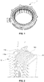
FIG. 1 is a view schematically illustrating a driving motor for environmentally friendly vehicles according to one form of the present disclosure; -
FIG. 2 is a view illustrating a coil lead-out portion of a driving motor for environmentally friendly vehicles according to one form of the present disclosure; -
FIG. 3 is an enlarged view of the box shown in dotted line inFIG. 1 to illustrate a bond state of a bonding portion of the driving motor for environmentally friendly vehicles according to one form of the present disclosure; -
FIG. 4 is a view illustrating a coil lead-out portion of a conventional driving motor for environmentally friendly vehicles; -
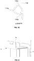
FIGS. 5A-5C are a view illustrating a coil lead-out portion having various shapes in the driving motor for environmentally friendly vehicles according to one form of the present disclosure; -
FIG. 6 is a view schematically illustrating a bobbin of the driving motor for environmentally friendly vehicles according to one form of the present disclosure; and -
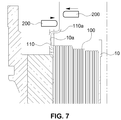
FIG. 7 is a view schematically illustrating a process of forming the coil lead-out portion of the driving motor for environmentally friendly vehicles according to one form of the present disclosure. - The drawings described herein are for illustration purposes only and are not intended to limit the scope of the present disclosure in any way.
- The following description is merely exemplary in nature and is not intended to limit the present disclosure, application, or uses. It should be understood that throughout the drawings, corresponding reference numerals indicate like or corresponding parts and features.
- It should be understood that the appended drawings are not necessarily to scale, presenting a somewhat simplified representation of various features illustrative of the basic principles of the present disclosure. The specific design features of the present disclosure as disclosed herein, including, for example, specific dimensions, orientations, locations, and shapes will be determined in part by the particular intended application and use environment.
- While the present disclosure will be described in conjunction with exemplary forms, it will be understood that present description is not intended to limit the present disclosure to those exemplary forms. On the contrary, the present disclosure is intended to cover not only the exemplary forms, but also various alternatives, modifications, equivalents and other forms, which may be included within the spirit and scope of the present disclosure as defined by the appended claims.
- As shown in
FIGS. 1 to 3 , the present disclosure relates to a drivingmotor 1 for environmentally friendly vehicles having astator core 12 and abobbin 10, which is formed as an insulating component to be assembled with thestator core 12. The drivingmotor 1 includes acoil part 100 wound on thestator core 12, a coil lead-outportion 110, and aterminal 300. - Typically, a
driving motor 1 of a concentrated winding type, especially a divisional core type, is structured such that thecoil part 100 is wound on thestator core 12 and such that the coil lead-outportion 110, which is formed as an end portion of thecoil part 100, is drawn straight, is assembled with theterminal 300, and forms an electrical path using a bonding method (fusing, welding, compression, etc.). - When the drawn coil lead-out
portion 110 is connected to theterminal 300, the coil lead-outportion 110 is drawn straight from thebobbin 10, which may cause disconnection of the coil lead-outportion 110 due to external vibration. - In other words, as shown in
FIG. 4 , since the coil lead-outportion 110 drawn from thebobbin 10 extends straight to be connected to theterminal 300, if external vibration occurs in the X-axis direction in the state in which both ends of the coil lead-outportion 110 are fixed, the coil lead-outportion 110 may be repeatedly bent and stretched, and subsequent disconnection of the coil lead-outportion 110 may occur. - Accordingly, in one form, the coil lead-out
portion 110 is formed to have a curved structure so as to increase the vibration resistance of the coil lead-outportion 110. - In detail, the coil lead-out
portion 110 is formed to have a plurality ofbent portions 110a, each having an angle of about 90 degrees or less. Accordingly, the coil lead-outportion 110 may have a curved structure having various shapes. - In one form, the coil lead-out
portion 110, as shown inFIGS. 5A-5C , may be formed to have any one of the shapes "C", "S" and "α". - After the winding of the
coil part 100, by forming the coil lead-outportion 110 to have a curved structure having any one of the shapes "C", "S" and "α" and by mechanically assembling and fixing the coil lead-outportion 110 to theterminal 300, the curved structure of the coil lead-outportion 110 can serve as a damper against external vibration. Therefore, even when external vibration occurs frequently, stress on thebonding portion 120 of theterminal 300 and the coil lead-outportion 110 may be dispersed, and consequently the possibility of fatigue fracture of the coil lead-outportion 110 may be remarkably reduced. - As a result, the vibration resistance feature of the coil lead-out
portion 110 can be improved by virtue of the above-described curved structure, and disconnection of the coil lead-outportion 110 attributable to external vibration can be inhibited or prevented, thereby avoiding deterioration in operational efficiency and fuel efficiency, which may be caused by an increase in resistance of the driving motor attributable to disconnection of the coil lead-outportion 110. - Because the coil lead-out
portion 110 according to the present disclosure has a curved structure instead of a conventional straight structure, the length of the coil lead-outportion 110 drawn from thebobbin 10 should be larger than the drawn length of the coil lead-out portion in the prior art. In the case of the "C"-shaped curved structure, the length of the coil lead-outportion 110 drawn from thebobbin 10 is set to be at least about 1.2 times as large as the drawn length in the prior art. - Hereafter, the process of forming the curved structure of the coil lead-out
portion 110 will be explained. - First, the
bobbin 10 is assembled to thestator core 12. - Next, the
coil part 100 is wound on thebobbin 10, and the coil lead-outportion 110 drawn from thebobbin 10 is formed to have a curved structure usingguide pins 200. - The coil lead-out
portion 110 is bonded to theterminal 300 using fusing, welding, compression or some other method. Since this bonding process is the same as the commonly known bonding process, a detailed explanation thereof will be omitted herein. - A portion of the coil lead-out
portion 110 is fitted into aguide recess 10a formed in thebobbin 10 so as to be fixed at a predetermined drawing position, and the coil lead-outportion 110 is formed to have various curved structures using movement of theguide pins 200 as illustrated inFIG. 6 . - As an example, when it is intended to form the coil lead-out
portion 110 to have an "S" shape, among the curved structures illustrated inFIGS. 5A-5C , a portion of the coil lead-outportion 110 is fitted into theguide recess 10a so as to be fixed at a predetermined drawing position, and, as shown inFIG. 7 , is then formed to have a plurality ofbent portions 110a by moving a pair ofguide pins 200 that face each other. - The guide pins 200 are arranged to face each other and pressurize the coil lead-out
portion 110 at different positions, so that the coil lead-outportion 110 has the above-described curved structure. - The guide pins 200 may be set to have a structure for forming the coil lead-out
portion 110 in a curved shape. For example, the number, position, length, etc. of the guide pins 200 may be variously set so as to satisfy the desired curved structure of the coil lead-outportion 110. - As is apparent from the above description, the present disclosure provides a driving motor for environmentally friendly vehicles, in which a coil lead-out portion drawn from a divisional core and extending to a terminal has a curved structure having a "C" shape, an "S" shape, an "α" shape or the like, thereby improving vibration resistance and inhibiting or preventing disconnection of the coil lead-out portion due to external vibration.
- As a result, the present disclosure has an effect of inhibiting or preventing deterioration in operational efficiency and fuel efficiency, which may be caused by an increase in resistance of the driving motor attributable to disconnection of the coil lead-out portion.
- The present disclosure has been described in detail with reference to forms thereof. However, it will be appreciated by those skilled in the art that changes may be made in these forms without departing from the principles and spirit of the present disclosure.
Claims (6)
- A driving motor for environmentally friendly vehicles having a stator core and a bobbin assembled to the stator core, the driving motor comprising:a coil part wound on the bobbin;a coil lead-out portion configured such that an end portion of the coil part drawn from the bobbin is formed to have a curved structure; anda terminal bonded with a bonding portion formed in the coil lead-out portion.
- The driving motor of claim 1, wherein the coil lead-out portion includes a plurality of bent portions, each having an angle of about 90 degrees or less.
- The driving motor of claim 2, wherein the coil lead-out portion is formed to have at least one of a "C" shape, an "S" shape or an "α" shape.
- The driving motor of claim 1, wherein the coil lead-out portion is fitted into a guide recess formed in the bobbin so as to be fixed at a predetermined drawing position.
- The driving motor of claim 4, wherein, after being fitted into the guide recess, the coil lead-out portion is formed to have a curved structure by moving a pair of guide pins arranged to face each other.
- The driving motor of claim 5, wherein a number and a position of the guide pins are set to form a curved structure of the coil lead-out portion.
Applications Claiming Priority (1)
| Application Number | Priority Date | Filing Date | Title |
|---|---|---|---|
| KR20160048002 | 2016-04-20 |
Publications (2)
| Publication Number | Publication Date |
|---|---|
| EP3236563A1 true EP3236563A1 (en) | 2017-10-25 |
| EP3236563B1 EP3236563B1 (en) | 2018-10-17 |
Family
ID=57714411
Family Applications (1)
| Application Number | Title | Priority Date | Filing Date |
|---|---|---|---|
| EP16205301.1A Active EP3236563B1 (en) | 2016-04-20 | 2016-12-20 | Driving motor for environmentally friendly vehicles |
Country Status (4)
| Country | Link |
|---|---|
| US (1) | US10411541B2 (en) |
| EP (1) | EP3236563B1 (en) |
| JP (1) | JP2017195759A (en) |
| CN (1) | CN107306059A (en) |
Families Citing this family (2)
| Publication number | Priority date | Publication date | Assignee | Title |
|---|---|---|---|---|
| US10862376B2 (en) * | 2018-08-07 | 2020-12-08 | Makita Corporation | Electric work machine |
| JP7268508B2 (en) * | 2019-07-09 | 2023-05-08 | 株式会社デンソー | Coil module and power converter |
Citations (2)
| Publication number | Priority date | Publication date | Assignee | Title |
|---|---|---|---|---|
| EP2731237A2 (en) * | 2012-11-08 | 2014-05-14 | LG Innotek Co., Ltd. | Terminal housing for motor and motor employing the same |
| EP2947754A1 (en) * | 2013-01-15 | 2015-11-25 | Mikuni Corporation | Electric motor, pump device using electric motor, and stator |
Family Cites Families (16)
| Publication number | Priority date | Publication date | Assignee | Title |
|---|---|---|---|---|
| US698237A (en) * | 1901-12-20 | 1902-04-22 | Burton E Wilder | Electric vapor-lighter. |
| JPH0686302U (en) | 1993-05-28 | 1994-12-13 | 富士通株式会社 | Coil member |
| JP3421251B2 (en) * | 1998-08-21 | 2003-06-30 | ミネベア株式会社 | Rotating electric machine and its bobbin |
| US6968237B2 (en) * | 2002-05-22 | 2005-11-22 | Pacesetter, Inc. | Implantable coronary sinus lead and lead system |
| JP2007129847A (en) * | 2005-11-04 | 2007-05-24 | Denso Corp | Electric motor and fuel pump using the same |
| JP4860546B2 (en) * | 2007-05-23 | 2012-01-25 | ミネベア株式会社 | Coil bobbin and manufacturing method thereof |
| KR100981111B1 (en) | 2008-12-30 | 2010-09-08 | 주식회사 포스코 | Nak coke treatment system and Nak coke treatment method |
| KR101163475B1 (en) * | 2010-03-08 | 2012-07-18 | 현대자동차주식회사 | Terminal assembly for motor of hybrid vehicle |
| KR101317892B1 (en) * | 2011-01-24 | 2013-10-16 | 주식회사 아모텍 | Amorphous Stator and Producing Method thereof |
| KR20130012719A (en) | 2011-07-26 | 2013-02-05 | 현대모비스 주식회사 | Bobbin of motor for vehicle |
| KR20130028566A (en) | 2011-09-09 | 2013-03-19 | 엘지전자 주식회사 | Stator and methed for manufacturing of stator and electric motor having thereof, electric vechile having electric motor |
| KR101319500B1 (en) | 2011-09-09 | 2013-10-17 | 엘지전자 주식회사 | Methed for manufacturing of stator and electric motor having thereof, electric vechile having electric motor |
| JP6095414B2 (en) * | 2013-02-27 | 2017-03-15 | 株式会社ミツバ | Flat wire winding method |
| KR102255748B1 (en) | 2013-12-31 | 2021-05-25 | 현대모비스 주식회사 | Stator, Driving motor having the same |
| DE102014213025A1 (en) * | 2014-07-04 | 2016-01-07 | Zf Friedrichshafen Ag | Coil for an electric machine |
| KR102255320B1 (en) * | 2014-07-10 | 2021-05-24 | 현대모비스 주식회사 | Power supply apparatus for vehicle and Insulation structure applied to the same |
-
2016
- 2016-12-14 US US15/378,181 patent/US10411541B2/en active Active
- 2016-12-15 CN CN201611158214.7A patent/CN107306059A/en active Pending
- 2016-12-20 EP EP16205301.1A patent/EP3236563B1/en active Active
- 2016-12-22 JP JP2016249739A patent/JP2017195759A/en active Pending
Patent Citations (2)
| Publication number | Priority date | Publication date | Assignee | Title |
|---|---|---|---|---|
| EP2731237A2 (en) * | 2012-11-08 | 2014-05-14 | LG Innotek Co., Ltd. | Terminal housing for motor and motor employing the same |
| EP2947754A1 (en) * | 2013-01-15 | 2015-11-25 | Mikuni Corporation | Electric motor, pump device using electric motor, and stator |
Also Published As
| Publication number | Publication date |
|---|---|
| EP3236563B1 (en) | 2018-10-17 |
| US20170310180A1 (en) | 2017-10-26 |
| CN107306059A (en) | 2017-10-31 |
| US10411541B2 (en) | 2019-09-10 |
| JP2017195759A (en) | 2017-10-26 |
Similar Documents
| Publication | Publication Date | Title |
|---|---|---|
| JP6417600B2 (en) | Bus bar unit and bus bar unit manufacturing method | |
| US9908424B2 (en) | Wireless charging system | |
| JP2005235443A (en) | Connector fixing structure | |
| JP5278795B2 (en) | Coil parts | |
| US9876400B2 (en) | Rotor of wound rotor synchronous motor | |
| JP2012005272A (en) | Integrated shield protector and wire harness | |
| JP6645024B2 (en) | Wiring member | |
| US20220190414A1 (en) | Battery-Mounting Structure | |
| JP6444653B2 (en) | Stator and electric pump | |
| EP3236563B1 (en) | Driving motor for environmentally friendly vehicles | |
| JP7403395B2 (en) | electromagnetic suspension | |
| US20150172821A1 (en) | Sound generator for vehicle | |
| US11108299B2 (en) | Fixture, fixing assembly, and fixation method for fixing power line to base member | |
| US20170163121A1 (en) | Rotor of wound rotate synchronous motor | |
| JP2009219301A (en) | Stator assembling method | |
| KR20160006934A (en) | Power supply apparatus for vehicle and Insulation structure applied to the same | |
| US9917493B2 (en) | Method for fixing permanent magnets of rotor | |
| CN109866612B (en) | Transmission mounts for vehicles | |
| JP7629426B2 (en) | Protector | |
| JP2024132421A (en) | Wire harnesses and protectors | |
| JP2007014090A (en) | High-voltage harness wiring structure for electric vehicles | |
| KR20190074529A (en) | A band cable for an automobile | |
| JP2013223339A (en) | Insulation type switching power supply device | |
| CN220890903U (en) | A vibration-damping rubber bushing | |
| CN207765634U (en) | Ground wire terminal and car |
Legal Events
| Date | Code | Title | Description |
|---|---|---|---|
| PUAI | Public reference made under article 153(3) epc to a published international application that has entered the european phase |
Free format text: ORIGINAL CODE: 0009012 |
|
| STAA | Information on the status of an ep patent application or granted ep patent |
Free format text: STATUS: THE APPLICATION HAS BEEN PUBLISHED |
|
| AK | Designated contracting states |
Kind code of ref document: A1 Designated state(s): AL AT BE BG CH CY CZ DE DK EE ES FI FR GB GR HR HU IE IS IT LI LT LU LV MC MK MT NL NO PL PT RO RS SE SI SK SM TR |
|
| AX | Request for extension of the european patent |
Extension state: BA ME |
|
| STAA | Information on the status of an ep patent application or granted ep patent |
Free format text: STATUS: REQUEST FOR EXAMINATION WAS MADE |
|
| 17P | Request for examination filed |
Effective date: 20171114 |
|
| RBV | Designated contracting states (corrected) |
Designated state(s): AL AT BE BG CH CY CZ DE DK EE ES FI FR GB GR HR HU IE IS IT LI LT LU LV MC MK MT NL NO PL PT RO RS SE SI SK SM TR |
|
| REG | Reference to a national code |
Ref country code: DE Ref legal event code: R079 Ref document number: 602016006523 Country of ref document: DE Free format text: PREVIOUS MAIN CLASS: H02K0003460000 Ipc: H02K0003520000 |
|
| GRAJ | Information related to disapproval of communication of intention to grant by the applicant or resumption of examination proceedings by the epo deleted |
Free format text: ORIGINAL CODE: EPIDOSDIGR1 |
|
| STAA | Information on the status of an ep patent application or granted ep patent |
Free format text: STATUS: GRANT OF PATENT IS INTENDED |
|
| GRAP | Despatch of communication of intention to grant a patent |
Free format text: ORIGINAL CODE: EPIDOSNIGR1 |
|
| RIC1 | Information provided on ipc code assigned before grant |
Ipc: H01F 5/04 20060101ALI20180329BHEP Ipc: H02K 3/52 20060101AFI20180329BHEP |
|
| INTG | Intention to grant announced |
Effective date: 20180502 |
|
| GRAS | Grant fee paid |
Free format text: ORIGINAL CODE: EPIDOSNIGR3 |
|
| GRAA | (expected) grant |
Free format text: ORIGINAL CODE: 0009210 |
|
| STAA | Information on the status of an ep patent application or granted ep patent |
Free format text: STATUS: THE PATENT HAS BEEN GRANTED |
|
| AK | Designated contracting states |
Kind code of ref document: B1 Designated state(s): AL AT BE BG CH CY CZ DE DK EE ES FI FR GB GR HR HU IE IS IT LI LT LU LV MC MK MT NL NO PL PT RO RS SE SI SK SM TR |
|
| REG | Reference to a national code |
Ref country code: GB Ref legal event code: FG4D |
|
| REG | Reference to a national code |
Ref country code: CH Ref legal event code: EP |
|
| REG | Reference to a national code |
Ref country code: IE Ref legal event code: FG4D |
|
| REG | Reference to a national code |
Ref country code: DE Ref legal event code: R096 Ref document number: 602016006523 Country of ref document: DE Ref country code: AT Ref legal event code: REF Ref document number: 1055134 Country of ref document: AT Kind code of ref document: T Effective date: 20181115 |
|
| REG | Reference to a national code |
Ref country code: NL Ref legal event code: MP Effective date: 20181017 |
|
| REG | Reference to a national code |
Ref country code: LT Ref legal event code: MG4D |
|
| REG | Reference to a national code |
Ref country code: AT Ref legal event code: MK05 Ref document number: 1055134 Country of ref document: AT Kind code of ref document: T Effective date: 20181017 |
|
| PG25 | Lapsed in a contracting state [announced via postgrant information from national office to epo] |
Ref country code: NL Free format text: LAPSE BECAUSE OF FAILURE TO SUBMIT A TRANSLATION OF THE DESCRIPTION OR TO PAY THE FEE WITHIN THE PRESCRIBED TIME-LIMIT Effective date: 20181017 |
|
| PG25 | Lapsed in a contracting state [announced via postgrant information from national office to epo] |
Ref country code: ES Free format text: LAPSE BECAUSE OF FAILURE TO SUBMIT A TRANSLATION OF THE DESCRIPTION OR TO PAY THE FEE WITHIN THE PRESCRIBED TIME-LIMIT Effective date: 20181017 Ref country code: LV Free format text: LAPSE BECAUSE OF FAILURE TO SUBMIT A TRANSLATION OF THE DESCRIPTION OR TO PAY THE FEE WITHIN THE PRESCRIBED TIME-LIMIT Effective date: 20181017 Ref country code: HR Free format text: LAPSE BECAUSE OF FAILURE TO SUBMIT A TRANSLATION OF THE DESCRIPTION OR TO PAY THE FEE WITHIN THE PRESCRIBED TIME-LIMIT Effective date: 20181017 Ref country code: PL Free format text: LAPSE BECAUSE OF FAILURE TO SUBMIT A TRANSLATION OF THE DESCRIPTION OR TO PAY THE FEE WITHIN THE PRESCRIBED TIME-LIMIT Effective date: 20181017 Ref country code: NO Free format text: LAPSE BECAUSE OF FAILURE TO SUBMIT A TRANSLATION OF THE DESCRIPTION OR TO PAY THE FEE WITHIN THE PRESCRIBED TIME-LIMIT Effective date: 20190117 Ref country code: BG Free format text: LAPSE BECAUSE OF FAILURE TO SUBMIT A TRANSLATION OF THE DESCRIPTION OR TO PAY THE FEE WITHIN THE PRESCRIBED TIME-LIMIT Effective date: 20190117 Ref country code: LT Free format text: LAPSE BECAUSE OF FAILURE TO SUBMIT A TRANSLATION OF THE DESCRIPTION OR TO PAY THE FEE WITHIN THE PRESCRIBED TIME-LIMIT Effective date: 20181017 Ref country code: FI Free format text: LAPSE BECAUSE OF FAILURE TO SUBMIT A TRANSLATION OF THE DESCRIPTION OR TO PAY THE FEE WITHIN THE PRESCRIBED TIME-LIMIT Effective date: 20181017 Ref country code: IS Free format text: LAPSE BECAUSE OF FAILURE TO SUBMIT A TRANSLATION OF THE DESCRIPTION OR TO PAY THE FEE WITHIN THE PRESCRIBED TIME-LIMIT Effective date: 20190217 Ref country code: AT Free format text: LAPSE BECAUSE OF FAILURE TO SUBMIT A TRANSLATION OF THE DESCRIPTION OR TO PAY THE FEE WITHIN THE PRESCRIBED TIME-LIMIT Effective date: 20181017 |
|
| PG25 | Lapsed in a contracting state [announced via postgrant information from national office to epo] |
Ref country code: SE Free format text: LAPSE BECAUSE OF FAILURE TO SUBMIT A TRANSLATION OF THE DESCRIPTION OR TO PAY THE FEE WITHIN THE PRESCRIBED TIME-LIMIT Effective date: 20181017 Ref country code: AL Free format text: LAPSE BECAUSE OF FAILURE TO SUBMIT A TRANSLATION OF THE DESCRIPTION OR TO PAY THE FEE WITHIN THE PRESCRIBED TIME-LIMIT Effective date: 20181017 Ref country code: PT Free format text: LAPSE BECAUSE OF FAILURE TO SUBMIT A TRANSLATION OF THE DESCRIPTION OR TO PAY THE FEE WITHIN THE PRESCRIBED TIME-LIMIT Effective date: 20190217 Ref country code: GR Free format text: LAPSE BECAUSE OF FAILURE TO SUBMIT A TRANSLATION OF THE DESCRIPTION OR TO PAY THE FEE WITHIN THE PRESCRIBED TIME-LIMIT Effective date: 20190118 Ref country code: RS Free format text: LAPSE BECAUSE OF FAILURE TO SUBMIT A TRANSLATION OF THE DESCRIPTION OR TO PAY THE FEE WITHIN THE PRESCRIBED TIME-LIMIT Effective date: 20181017 |
|
| REG | Reference to a national code |
Ref country code: DE Ref legal event code: R097 Ref document number: 602016006523 Country of ref document: DE |
|
| PG25 | Lapsed in a contracting state [announced via postgrant information from national office to epo] |
Ref country code: CZ Free format text: LAPSE BECAUSE OF FAILURE TO SUBMIT A TRANSLATION OF THE DESCRIPTION OR TO PAY THE FEE WITHIN THE PRESCRIBED TIME-LIMIT Effective date: 20181017 Ref country code: DK Free format text: LAPSE BECAUSE OF FAILURE TO SUBMIT A TRANSLATION OF THE DESCRIPTION OR TO PAY THE FEE WITHIN THE PRESCRIBED TIME-LIMIT Effective date: 20181017 Ref country code: IT Free format text: LAPSE BECAUSE OF FAILURE TO SUBMIT A TRANSLATION OF THE DESCRIPTION OR TO PAY THE FEE WITHIN THE PRESCRIBED TIME-LIMIT Effective date: 20181017 |
|
| PLBE | No opposition filed within time limit |
Free format text: ORIGINAL CODE: 0009261 |
|
| STAA | Information on the status of an ep patent application or granted ep patent |
Free format text: STATUS: NO OPPOSITION FILED WITHIN TIME LIMIT |
|
| PG25 | Lapsed in a contracting state [announced via postgrant information from national office to epo] |
Ref country code: SK Free format text: LAPSE BECAUSE OF FAILURE TO SUBMIT A TRANSLATION OF THE DESCRIPTION OR TO PAY THE FEE WITHIN THE PRESCRIBED TIME-LIMIT Effective date: 20181017 Ref country code: RO Free format text: LAPSE BECAUSE OF FAILURE TO SUBMIT A TRANSLATION OF THE DESCRIPTION OR TO PAY THE FEE WITHIN THE PRESCRIBED TIME-LIMIT Effective date: 20181017 Ref country code: LU Free format text: LAPSE BECAUSE OF NON-PAYMENT OF DUE FEES Effective date: 20181220 Ref country code: MC Free format text: LAPSE BECAUSE OF FAILURE TO SUBMIT A TRANSLATION OF THE DESCRIPTION OR TO PAY THE FEE WITHIN THE PRESCRIBED TIME-LIMIT Effective date: 20181017 Ref country code: SM Free format text: LAPSE BECAUSE OF FAILURE TO SUBMIT A TRANSLATION OF THE DESCRIPTION OR TO PAY THE FEE WITHIN THE PRESCRIBED TIME-LIMIT Effective date: 20181017 Ref country code: EE Free format text: LAPSE BECAUSE OF FAILURE TO SUBMIT A TRANSLATION OF THE DESCRIPTION OR TO PAY THE FEE WITHIN THE PRESCRIBED TIME-LIMIT Effective date: 20181017 |
|
| REG | Reference to a national code |
Ref country code: IE Ref legal event code: MM4A |
|
| 26N | No opposition filed |
Effective date: 20190718 |
|
| REG | Reference to a national code |
Ref country code: BE Ref legal event code: MM Effective date: 20181231 |
|
| PG25 | Lapsed in a contracting state [announced via postgrant information from national office to epo] |
Ref country code: SI Free format text: LAPSE BECAUSE OF FAILURE TO SUBMIT A TRANSLATION OF THE DESCRIPTION OR TO PAY THE FEE WITHIN THE PRESCRIBED TIME-LIMIT Effective date: 20181017 Ref country code: IE Free format text: LAPSE BECAUSE OF NON-PAYMENT OF DUE FEES Effective date: 20181220 |
|
| PG25 | Lapsed in a contracting state [announced via postgrant information from national office to epo] |
Ref country code: BE Free format text: LAPSE BECAUSE OF NON-PAYMENT OF DUE FEES Effective date: 20181231 |
|
| PG25 | Lapsed in a contracting state [announced via postgrant information from national office to epo] |
Ref country code: MT Free format text: LAPSE BECAUSE OF NON-PAYMENT OF DUE FEES Effective date: 20181220 |
|
| PG25 | Lapsed in a contracting state [announced via postgrant information from national office to epo] |
Ref country code: TR Free format text: LAPSE BECAUSE OF FAILURE TO SUBMIT A TRANSLATION OF THE DESCRIPTION OR TO PAY THE FEE WITHIN THE PRESCRIBED TIME-LIMIT Effective date: 20181017 |
|
| PG25 | Lapsed in a contracting state [announced via postgrant information from national office to epo] |
Ref country code: CY Free format text: LAPSE BECAUSE OF FAILURE TO SUBMIT A TRANSLATION OF THE DESCRIPTION OR TO PAY THE FEE WITHIN THE PRESCRIBED TIME-LIMIT Effective date: 20181017 Ref country code: MK Free format text: LAPSE BECAUSE OF NON-PAYMENT OF DUE FEES Effective date: 20181017 Ref country code: HU Free format text: LAPSE BECAUSE OF FAILURE TO SUBMIT A TRANSLATION OF THE DESCRIPTION OR TO PAY THE FEE WITHIN THE PRESCRIBED TIME-LIMIT; INVALID AB INITIO Effective date: 20161220 |
|
| REG | Reference to a national code |
Ref country code: CH Ref legal event code: PL |
|
| PG25 | Lapsed in a contracting state [announced via postgrant information from national office to epo] |
Ref country code: CH Free format text: LAPSE BECAUSE OF NON-PAYMENT OF DUE FEES Effective date: 20191231 Ref country code: LI Free format text: LAPSE BECAUSE OF NON-PAYMENT OF DUE FEES Effective date: 20191231 |
|
| P01 | Opt-out of the competence of the unified patent court (upc) registered |
Effective date: 20230511 |
|
| PGFP | Annual fee paid to national office [announced via postgrant information from national office to epo] |
Ref country code: DE Payment date: 20251120 Year of fee payment: 10 |
|
| PGFP | Annual fee paid to national office [announced via postgrant information from national office to epo] |
Ref country code: GB Payment date: 20251120 Year of fee payment: 10 |
|
| PGFP | Annual fee paid to national office [announced via postgrant information from national office to epo] |
Ref country code: FR Payment date: 20251125 Year of fee payment: 10 |