EP3236546A2 - Fiber temperature control assembly - Google Patents
Fiber temperature control assembly Download PDFInfo
- Publication number
- EP3236546A2 EP3236546A2 EP16178819.5A EP16178819A EP3236546A2 EP 3236546 A2 EP3236546 A2 EP 3236546A2 EP 16178819 A EP16178819 A EP 16178819A EP 3236546 A2 EP3236546 A2 EP 3236546A2
- Authority
- EP
- European Patent Office
- Prior art keywords
- fiber
- spool
- temperature control
- control assembly
- holding element
- Prior art date
- Legal status (The legal status is an assumption and is not a legal conclusion. Google has not performed a legal analysis and makes no representation as to the accuracy of the status listed.)
- Granted
Links
Images




Classifications
-
- H—ELECTRICITY
- H01—ELECTRIC ELEMENTS
- H01S—DEVICES USING THE PROCESS OF LIGHT AMPLIFICATION BY STIMULATED EMISSION OF RADIATION [LASER] TO AMPLIFY OR GENERATE LIGHT; DEVICES USING STIMULATED EMISSION OF ELECTROMAGNETIC RADIATION IN WAVE RANGES OTHER THAN OPTICAL
- H01S3/00—Lasers, i.e. devices using stimulated emission of electromagnetic radiation in the infrared, visible or ultraviolet wave range
- H01S3/02—Constructional details
- H01S3/04—Arrangements for thermal management
-
- H—ELECTRICITY
- H01—ELECTRIC ELEMENTS
- H01S—DEVICES USING THE PROCESS OF LIGHT AMPLIFICATION BY STIMULATED EMISSION OF RADIATION [LASER] TO AMPLIFY OR GENERATE LIGHT; DEVICES USING STIMULATED EMISSION OF ELECTROMAGNETIC RADIATION IN WAVE RANGES OTHER THAN OPTICAL
- H01S3/00—Lasers, i.e. devices using stimulated emission of electromagnetic radiation in the infrared, visible or ultraviolet wave range
- H01S3/02—Constructional details
- H01S3/04—Arrangements for thermal management
- H01S3/0405—Conductive cooling, e.g. by heat sinks or thermo-electric elements
-
- H—ELECTRICITY
- H01—ELECTRIC ELEMENTS
- H01S—DEVICES USING THE PROCESS OF LIGHT AMPLIFICATION BY STIMULATED EMISSION OF RADIATION [LASER] TO AMPLIFY OR GENERATE LIGHT; DEVICES USING STIMULATED EMISSION OF ELECTROMAGNETIC RADIATION IN WAVE RANGES OTHER THAN OPTICAL
- H01S3/00—Lasers, i.e. devices using stimulated emission of electromagnetic radiation in the infrared, visible or ultraviolet wave range
- H01S3/05—Construction or shape of optical resonators; Accommodation of active medium therein; Shape of active medium
- H01S3/06—Construction or shape of active medium
- H01S3/063—Waveguide lasers, i.e. whereby the dimensions of the waveguide are of the order of the light wavelength
- H01S3/067—Fibre lasers
- H01S3/06704—Housings; Packages
-
- H—ELECTRICITY
- H01—ELECTRIC ELEMENTS
- H01S—DEVICES USING THE PROCESS OF LIGHT AMPLIFICATION BY STIMULATED EMISSION OF RADIATION [LASER] TO AMPLIFY OR GENERATE LIGHT; DEVICES USING STIMULATED EMISSION OF ELECTROMAGNETIC RADIATION IN WAVE RANGES OTHER THAN OPTICAL
- H01S3/00—Lasers, i.e. devices using stimulated emission of electromagnetic radiation in the infrared, visible or ultraviolet wave range
- H01S3/05—Construction or shape of optical resonators; Accommodation of active medium therein; Shape of active medium
- H01S3/06—Construction or shape of active medium
- H01S3/063—Waveguide lasers, i.e. whereby the dimensions of the waveguide are of the order of the light wavelength
- H01S3/067—Fibre lasers
- H01S3/06754—Fibre amplifiers
-
- H—ELECTRICITY
- H01—ELECTRIC ELEMENTS
- H01S—DEVICES USING THE PROCESS OF LIGHT AMPLIFICATION BY STIMULATED EMISSION OF RADIATION [LASER] TO AMPLIFY OR GENERATE LIGHT; DEVICES USING STIMULATED EMISSION OF ELECTROMAGNETIC RADIATION IN WAVE RANGES OTHER THAN OPTICAL
- H01S3/00—Lasers, i.e. devices using stimulated emission of electromagnetic radiation in the infrared, visible or ultraviolet wave range
- H01S3/09—Processes or apparatus for excitation, e.g. pumping
- H01S3/091—Processes or apparatus for excitation, e.g. pumping using optical pumping
- H01S3/094—Processes or apparatus for excitation, e.g. pumping using optical pumping by coherent light
- H01S3/094003—Processes or apparatus for excitation, e.g. pumping using optical pumping by coherent light the pumped medium being a fibre
-
- H—ELECTRICITY
- H01—ELECTRIC ELEMENTS
- H01S—DEVICES USING THE PROCESS OF LIGHT AMPLIFICATION BY STIMULATED EMISSION OF RADIATION [LASER] TO AMPLIFY OR GENERATE LIGHT; DEVICES USING STIMULATED EMISSION OF ELECTROMAGNETIC RADIATION IN WAVE RANGES OTHER THAN OPTICAL
- H01S3/00—Lasers, i.e. devices using stimulated emission of electromagnetic radiation in the infrared, visible or ultraviolet wave range
- H01S3/14—Lasers, i.e. devices using stimulated emission of electromagnetic radiation in the infrared, visible or ultraviolet wave range characterised by the material used as the active medium
- H01S3/16—Solid materials
- H01S3/1601—Solid materials characterised by an active (lasing) ion
- H01S3/1603—Solid materials characterised by an active (lasing) ion rare earth
- H01S3/1608—Solid materials characterised by an active (lasing) ion rare earth erbium
-
- H—ELECTRICITY
- H01—ELECTRIC ELEMENTS
- H01S—DEVICES USING THE PROCESS OF LIGHT AMPLIFICATION BY STIMULATED EMISSION OF RADIATION [LASER] TO AMPLIFY OR GENERATE LIGHT; DEVICES USING STIMULATED EMISSION OF ELECTROMAGNETIC RADIATION IN WAVE RANGES OTHER THAN OPTICAL
- H01S3/00—Lasers, i.e. devices using stimulated emission of electromagnetic radiation in the infrared, visible or ultraviolet wave range
- H01S3/02—Constructional details
- H01S3/04—Arrangements for thermal management
- H01S3/042—Arrangements for thermal management for solid state lasers
-
- H—ELECTRICITY
- H01—ELECTRIC ELEMENTS
- H01S—DEVICES USING THE PROCESS OF LIGHT AMPLIFICATION BY STIMULATED EMISSION OF RADIATION [LASER] TO AMPLIFY OR GENERATE LIGHT; DEVICES USING STIMULATED EMISSION OF ELECTROMAGNETIC RADIATION IN WAVE RANGES OTHER THAN OPTICAL
- H01S3/00—Lasers, i.e. devices using stimulated emission of electromagnetic radiation in the infrared, visible or ultraviolet wave range
- H01S3/09—Processes or apparatus for excitation, e.g. pumping
- H01S3/091—Processes or apparatus for excitation, e.g. pumping using optical pumping
- H01S3/094—Processes or apparatus for excitation, e.g. pumping using optical pumping by coherent light
- H01S3/094049—Guiding of the pump light
- H01S3/094053—Fibre coupled pump, e.g. delivering pump light using a fibre or a fibre bundle
Definitions
- the invention relates to a fiber temperature control assembly and to a method for adjusting a temperature of a doped optical fiber wound around a fiber spool.
- repeaters basically did comprise a receiver followed by a transmitter.
- the incoming signal was converted from a light signal to an electrical signal by a receiver cleaned up to remove as much signal noise as possible and then retransmitted by another laser transmitter.
- these conventional repeaters add noise to the signal and consume much power.
- Other disadvantages of these conventional repeaters are their complexity and inflexibility.
- Fig. 1 shows schematically an optical amplifier.
- the optical amplifier comprises a doped optical fiber dOF between a coupler and a filter.
- a pump laser supplies energy to the amplifier while an incoming signal stimulates emission as a pulse passes through the doped optical fiber dOF.
- a stimulated emission is a rapid exponential growth of photons in the doped optical fiber.
- the doped optical fiber dOF then can be arranged in a fiber spool.
- a doped optical fiber dOF with a predetermined length can be wound around a fiber spool.
- the temperature of the optical fiber can be increased by means of a coil heater. If the coil heater is powered up the produced heat can be transferred to the fiber spool and hence to the doped optical fibers of the optical amplifier.
- a conventional arrangement has the disadvantage that it does not provide for a uniform heating of the individual optical fiber windings wound around the fiber spool. As a consequence, the doped optical fiber wound around the spool cannot be heated accurately and the gain flatness of the optical amplifier is diminished.
- the invention provides according to a first aspect a fiber temperature control assembly comprising a spool holding element adapted to hold a fiber spool and a compression element adapted to press fiber windings of a doped optical fiber wound around a fiber spool against said spool holding element being in thermal contact with a heating and/or cooling element of said fiber temperature control assembly.
- the compression element is a compression gasket consisting of a fire retardant low compression elastic material.
- the compression element is made of an electric isolating material.
- the compression element is adhered to a printed circuit board.
- the holding element comprises an aluminum element.
- the spool holding element comprises a cavity for receiving the fiber spool.
- the fiber temperature control assembly further comprises a fiber spool retainer element adapted to retain said fiber spool inserted in a cavity of said spool holding element.
- said heating element comprises a heating coil adhered to said spool holding element.
- the fiber spool retainer element is a thin flexible plate made of a fire retardant material.
- the doped optical fiber wound around said fiber spool is an erbium-doped optical fiber.
- the invention further provides according to a second aspect an optical amplifier comprising a doped optical fiber wound around a fiber spool, said optical amplifier comprising a fiber temperature control assembly for heating or cooling said doped optical fiber, wherein said fiber temperature control assembly comprises:
- the optical amplifier comprises a control circuit adapted to control a temperature of said doped optical fiber wound around said fiber spool.
- the optical amplifier comprises at least one pump laser adapted to generate pump power supplied to the doped optical fiber wound around said fiber spool.
- the pump power generated by the pump laser is supplied to the doped optical fiber wound around said fiber spool via fiber couplers of said optical amplifier.
- the invention further provides according to a third aspect a method for adjusting a temperature of a doped optical fiber wound around a fiber spool comprising the steps of:
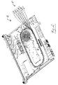
- Fig. 2 shows a perspective view on a possible exemplary embodiment of an optical amplifier 1 according to an aspect of the present invention.
- the optical amplifier 1 comprises a fiber track area including a doped optical fiber dOF having a spool holding element covered by a heating and/or cooling element.
- a spool holding element 2 is covered by a heating element 3.
- the spool holding element 2 is in thermal contact with the heating element 3 of the fiber temperature control assembly of the optical amplifier 1.
- the spool holding element 2 is adapted to hold a fiber spool of the optical fiber track.
- a fiber track 4 defines an area comprising the fiber temperature control assembly having the spool holding element 2 covered by the heating element 3.
- the optical amplifier 1 comprises pluggable fiber pigtails 5 as shown in Fig. 2 .
- the doped optical fiber dOF can be wound as illustrated in Fig. 2 in a circular fiber track 4 including a fiber spool held by the spool holding element 2 as shown in Fig. 2 .
- the doped optical fiber dOF can comprise for instance in a possible implementation an erbium-doped optical fiber.
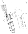
- Fig. 3 shows an explosive perspective view on the area defined by the fiber track 4 of the optical amplifier 1 from above.
- the spool holding element 2 as shown in Fig. 3 is adapted to hold a fiber spool of an optical fiber such as an erbium-doped optical fiber.
- the fiber temperature control assembly comprising the spool holding element 2 further comprises a compression element 6 adapted to press fiber windings of the doped optical fiber dOF wound around in a fiber spool against the spool holding element 2 which is in thermal contact with the heating and/or cooling element 3 as shown in Fig. 2 .
- the compression element 6 in a preferred embodiment is a compression gasket consisting of a fire retardant low compression elastic material.
- the compression element 6 can be mounted to a printed circuit board 7.
- the compression element 6 is made of an electric isolating material.
- the fiber temperature control assembly comprises in a possible embodiment a fiber spool retainer element 8 which is adapted to retain the fiber spool inserted into a cavity of the spool holding element 2.
- the fiber spool retainer element 8 can be formed by a flexible plate made of a fire retardant material such as Kapton material.
- Fig. 4 shows a perspective explosive view from below on the fiber temperature control assembly within the fiber track area 4.
- the spool holding element 2 is adapted to hold a loose fiber spool 9 comprising a plurality of fiber windings of the fiber track.
- the fiber spool retainer element 8 retains the loose fiber spool inserted in a cavity of the spool holding element 2.
- the heating/cooling element 3 can be attached to the surface of the spool holding element 2.
- the spool holding element 2 can be formed by a metal, in particular aluminum.
- the spool holding element 2 can be formed by a cast element comprising a cavity for receiving the loose fiber spool 9 retained by the fiber spool retainer element 8.
- the doped optical fiber dOF wound within the loose fiber spool 9 received by the cavity of the spool holding element 2 can be for instance an erbium-doped optical fiber.
- Several protrusions 10 of the fiber spool retainer element 8 retain the loose fiber spool 9 comprising a plurality of windings within the cavity of the spool holding element 2.
- Fig. 5 shows an enlarged view on the spool holding element 2 from below.
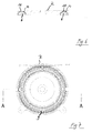
- Fig. 6 shows a sectional view along line A-A through a possible embodiment of the spool holding element 2 of the fiber temperature control assembly according to a possible embodiment of the present invention as shown in Fig. 7.
- Fig. 7 shows a front view on the spool holding element 2 from below.
- the loose fiber spool 9 is inserted into a cavity 11 of the spool holding element 2.
- the fiber spool 9 can be retained by the protrusions 10 of the fiber spool retainer element 8.
- the fiber spool 9 comprises a plurality of circular windings 12 wherein the compression element 6 pushes individual fiber strands 12 or fiber windings against the spool holding element 2 as illustrated in the sectional view of Fig. 6 .
- the compression element 6 pushes individual fiber strands 12 or fiber windings against the spool holding element 2 as illustrated in the sectional view of Fig. 6 .
- the compression element 6 is made of an elastic material.
- the compression element 6 can be a compression gasket consisting of a fire retardant low compression elastic material. As can be seen in Fig.
- the fiber windings are in direct thermal contact with the spool holding element 2 which allows a very accurate temperature control through the heating and/or cooling element 3 attached to the surface of the spool holding element 2 as shown in Fig. 1 .
- the element 3 can be for instance a Mila heater control element that is attached to the spool holding element 2.
- the spool holding element 2 can be formed by an aluminum die cast heat sink block. By pushing the single layer of fiber windings 12 against the spool holding element 2, a uniform heating of the whole fiber loop can be achieved.
- the spool holding element 2 can act as a heat sink or heat source. Further, the arrangement allows for using optical doped fibers of various diameters due to various compression depths inherent to the used compression gasket 6.
- the optical amplifier 1 can comprise a control circuit adapted to control a temperature T of the doped optical fiber dOF wound around the fiber spool 9.
- the optical amplifier 1 comprises at least one pump laser adapted to generate pump power supplied to the doped optical fiber within the fiber track 4 wound around the fiber spool hold by said spool holding element 2 of the fiber temperature control assembly.
- the pump power generated by the pump laser is supplied to the doped optical fiber wound within the fiber spool 9 via fiber couplers of the optical amplifier.
- Fig. 8 shows a flowchart of a possible exemplary embodiment of a method for adjusting a temperature T of a doped optical fiber wound within a fiber spool.
- a first step Sl fiber windings of the doped optical fiber are pressed by means of a flexible compression element such as the compression element 6 against a spool holding element such as the spool holding element 2 holding the fiber spool 9.
- the temperature of the spool holding element 2 is controlled by means of a heating element and/or a cooling element 3 being in thermal contact with the spool holding element 2.
- the method and assembly according to the present invention allows for individual optical doped fibers to be heated very accurately without the use of bonding or layer substrates. It further allows to employ optical doped fibers oDF with different diameters using the same heater device due to the flexible characteristics of the compression element 6.
- the isolation characteristics of the compression gasket 6 focus heating on the optical doped fibers dOF and not on the printed circuit board 7.
- the fiber temperature control assembly according to the present invention further allows ease of assembly resulting in a fast mounting of the optical amplifier 1. By achieving a very uniform heating of the different fiber windings 12 of the fiber spool 9 a very flat gain spectrum of the optical amplifier 1 can be achieved.
- the pressure force pressing the fiber windings 12 against the spool holding element 2 can be adjusted, for instance by means of a mechanical screw.
- the compression element 6 can be exchanged or replaced to define a predetermined pressure force F pressing the fiber windings 12 against the inner cavity 11 of the spool holding element 2.
- compression elements 6 or compression gaskets with different thickness can be used to define the pressure force F.
- the compression element gasket 6 can be replaced using gaskets with different elastic materials to define the pressure force F pressing the fiber windings 12 against the inner cavity 11 of the spool holding element 2.
- the optical amplifier 1 can be adapted to amplify wavelength division multiplexed, WDM, signals in the optical domain without conversion into the electrical baseband.
- the optical amplifier 1 is transparent with regard to protocols carried in individual WDM channels.
Landscapes
- Physics & Mathematics (AREA)
- Electromagnetism (AREA)
- Engineering & Computer Science (AREA)
- Plasma & Fusion (AREA)
- Optics & Photonics (AREA)
- Microelectronics & Electronic Packaging (AREA)
- Lasers (AREA)
- Control Of Temperature (AREA)
Abstract
a spool holding element adapted to hold a fiber spool and a compression element adapted to press fiber windings of a doped optical fiber wound around the fiber spool against said spool holding element being in thermal contact with a heating and/or cooling element of said fiber temperature control assembly.
Description
- The invention relates to a fiber temperature control assembly and to a method for adjusting a temperature of a doped optical fiber wound around a fiber spool.
- Although the low loss of optical fiber allows signals to travel hundreds of kilometers or miles, long haul lines require regenerators or repeaters to amplify the signal periodically. In the beginning, repeaters basically did comprise a receiver followed by a transmitter. The incoming signal was converted from a light signal to an electrical signal by a receiver cleaned up to remove as much signal noise as possible and then retransmitted by another laser transmitter. However, these conventional repeaters add noise to the signal and consume much power. Other disadvantages of these conventional repeaters are their complexity and inflexibility.
- Consequently the electronic repeaters have been widely replaced by optical amplifiers comprising doped optical fibers.
Fig. 1 shows schematically an optical amplifier. The optical amplifier comprises a doped optical fiber dOF between a coupler and a filter. A pump laser supplies energy to the amplifier while an incoming signal stimulates emission as a pulse passes through the doped optical fiber dOF. A stimulated emission is a rapid exponential growth of photons in the doped optical fiber. The doped optical fiber dOF then can be arranged in a fiber spool. In a conventional optical amplifier, a doped optical fiber dOF with a predetermined length can be wound around a fiber spool. In order to improve a gain flatness of the optical amplifier the temperature of the optical fiber can be increased by means of a coil heater. If the coil heater is powered up the produced heat can be transferred to the fiber spool and hence to the doped optical fibers of the optical amplifier. However, such a conventional arrangement has the disadvantage that it does not provide for a uniform heating of the individual optical fiber windings wound around the fiber spool. As a consequence, the doped optical fiber wound around the spool cannot be heated accurately and the gain flatness of the optical amplifier is diminished. - Accordingly, it is an object of the present invention to provide a fiber temperature control assembly which provides a uniform heating of the doped optical fiber wound around a fiber spool to improve gain flatness of the optical amplifier.
- The invention provides according to a first aspect a fiber temperature control assembly comprising
a spool holding element adapted to hold a fiber spool and a compression element adapted to press fiber windings of a doped optical fiber wound around a fiber spool against said spool holding element being in thermal contact with a heating and/or cooling element of said fiber temperature control assembly. - In a possible embodiment of the fiber temperature control assembly according to the first aspect of the present invention, the compression element is a compression gasket consisting of a fire retardant low compression elastic material.
- In a possible embodiment of the fiber temperature control assembly according to the first aspect of the present invention, the compression element is made of an electric isolating material.
- In a further possible embodiment of the fiber temperature control assembly according to the first aspect of the present invention, the compression element is adhered to a printed circuit board.
- In a still further possible embodiment of the fiber temperature control assembly according to the first aspect of the present invention, the holding element comprises an aluminum element.
- In a still further possible embodiment of the fiber temperature control assembly according to the first aspect of the present invention, the spool holding element comprises a cavity for receiving the fiber spool.
- In a further possible embodiment of the fiber temperature control assembly according to the first aspect of the present invention, the fiber temperature control assembly further comprises a fiber spool retainer element adapted to retain said fiber spool inserted in a cavity of said spool holding element.
- In a further possible embodiment of the fiber temperature control assembly according to the first aspect of the present invention, said heating element comprises a heating coil adhered to said spool holding element.
- In a further possible embodiment of the fiber temperature control assembly according to the first aspect of the present invention, the fiber spool retainer element is a thin flexible plate made of a fire retardant material.
- In a still further possible embodiment of the fiber temperature control assembly according to the first aspect of the present invention, the doped optical fiber wound around said fiber spool is an erbium-doped optical fiber.
- The invention further provides according to a second aspect an optical amplifier comprising a doped optical fiber wound around a fiber spool, said optical amplifier comprising a fiber temperature control assembly for heating or cooling said doped optical fiber,
wherein said fiber temperature control assembly comprises: - a spool holding element adapted to hold said fiber spool and a compression element adapted to press fiber windings of the doped optical fiber wound around said fiber spool against said spool holding element being in thermal contact with a heating and/or cooling element of said fiber temperature control assembly.
- In a possible embodiment of the optical amplifier according to the second aspect of the present invention, the optical amplifier comprises a control circuit adapted to control a temperature of said doped optical fiber wound around said fiber spool.
- In a still further possible embodiment of the optical amplifier according to the second aspect of the present invention, the optical amplifier comprises at least one pump laser adapted to generate pump power supplied to the doped optical fiber wound around said fiber spool.
- In a further possible embodiment of the optical amplifier according to the second aspect of the present invention, the pump power generated by the pump laser is supplied to the doped optical fiber wound around said fiber spool via fiber couplers of said optical amplifier.
- The invention further provides according to a third aspect a method for adjusting a temperature of a doped optical fiber wound around a fiber spool comprising the steps of:
- pressing fiber windings of the doped optical fiber by a flexible compression element against a spool holding element holding said fiber spool, and
- controlling the temperature of said spool holding element by means of a heating element and/or by means of a cooling element being in thermal contact with said spool holding element.
- In the following, possible embodiments of the different aspects of the present invention are described in more detail with reference to the enclosed figures.
- Fig. 1
- shows schematically a conventional optical amplifier;
- Fig. 2
- shows a perspective view on an optical amplifier according to an aspect of the present invention comprising a fiber temperature control assembly according to the present invention;
- Fig. 3
- shows a perspective explosive view from above on the fiber track area within an optical amplifier illustrated in
Fig. 2 comprising a fiber temperature control assembly according to an embodiment of the present invention; - Fig. 4
- shows a perspective explosive view from below on a fiber track portion of the optical amplifier illustrated in
Fig. 2 comprising a fiber temperature control assembly according to a possible embodiment of the present invention; - Fig. 5
- shows a detailed view on a spool holding element of a fiber temperature control assembly according to a possible embodiment of the present invention;
- Fig. 6
- shows a sectional view on a spool holding element of the fiber temperature control assembly according to a possible embodiment of the present invention;
- Fig. 7
- shows a front view on a spool holding element as used in a fiber temperature control assembly according to a possible embodiment;
- Fig. 8
- illustrates a flow chart of an exemplary embodiment of a method for adjusting a temperature of a doped optical fiber according to a further aspect of the present invention.
-
Fig. 2 shows a perspective view on a possible exemplary embodiment of an optical amplifier 1 according to an aspect of the present invention. - The optical amplifier 1 comprises a fiber track area including a doped optical fiber dOF having a spool holding element covered by a heating and/or cooling element. In the illustrated exemplary embodiment of the optical amplifier 1 as shown in
Fig. 2 , aspool holding element 2 is covered by aheating element 3. Thespool holding element 2 is in thermal contact with theheating element 3 of the fiber temperature control assembly of the optical amplifier 1. Thespool holding element 2 is adapted to hold a fiber spool of the optical fiber track. A fiber track 4 defines an area comprising the fiber temperature control assembly having thespool holding element 2 covered by theheating element 3. The optical amplifier 1 comprisespluggable fiber pigtails 5 as shown inFig. 2 . The doped optical fiber dOF can be wound as illustrated inFig. 2 in a circular fiber track 4 including a fiber spool held by thespool holding element 2 as shown inFig. 2 . The doped optical fiber dOF can comprise for instance in a possible implementation an erbium-doped optical fiber. -
Fig. 3 shows an explosive perspective view on the area defined by the fiber track 4 of the optical amplifier 1 from above. Thespool holding element 2 as shown inFig. 3 is adapted to hold a fiber spool of an optical fiber such as an erbium-doped optical fiber. The fiber temperature control assembly comprising thespool holding element 2 further comprises a compression element 6 adapted to press fiber windings of the doped optical fiber dOF wound around in a fiber spool against thespool holding element 2 which is in thermal contact with the heating and/orcooling element 3 as shown inFig. 2 . The compression element 6 in a preferred embodiment is a compression gasket consisting of a fire retardant low compression elastic material. The compression element 6 can be mounted to a printedcircuit board 7. In a possible embodiment, the compression element 6 is made of an electric isolating material. The fiber temperature control assembly comprises in a possible embodiment a fiberspool retainer element 8 which is adapted to retain the fiber spool inserted into a cavity of thespool holding element 2. In a possible embodiment, the fiberspool retainer element 8 can be formed by a flexible plate made of a fire retardant material such as Kapton material. -
Fig. 4 shows a perspective explosive view from below on the fiber temperature control assembly within the fiber track area 4. As can be seen inFig. 4 , thespool holding element 2 is adapted to hold a loose fiber spool 9 comprising a plurality of fiber windings of the fiber track. The fiberspool retainer element 8 retains the loose fiber spool inserted in a cavity of thespool holding element 2. The heating/cooling element 3 can be attached to the surface of thespool holding element 2. In a possible embodiment, thespool holding element 2 can be formed by a metal, in particular aluminum. Thespool holding element 2 can be formed by a cast element comprising a cavity for receiving the loose fiber spool 9 retained by the fiberspool retainer element 8. The doped optical fiber dOF wound within the loose fiber spool 9 received by the cavity of thespool holding element 2 can be for instance an erbium-doped optical fiber.Several protrusions 10 of the fiberspool retainer element 8 retain the loose fiber spool 9 comprising a plurality of windings within the cavity of thespool holding element 2. -
Fig. 5 shows an enlarged view on thespool holding element 2 from below.Fig. 6 shows a sectional view along line A-A through a possible embodiment of thespool holding element 2 of the fiber temperature control assembly according to a possible embodiment of the present invention as shown inFig. 7. Fig. 7 shows a front view on thespool holding element 2 from below. As can be seen inFig. 7 , the loose fiber spool 9 is inserted into acavity 11 of thespool holding element 2. The fiber spool 9 can be retained by theprotrusions 10 of the fiberspool retainer element 8. The fiber spool 9 comprises a plurality ofcircular windings 12 wherein the compression element 6 pushesindividual fiber strands 12 or fiber windings against thespool holding element 2 as illustrated in the sectional view ofFig. 6 . As can be seen inFig. 6 , there is a single layer of fiber windings orfiber strands 12 pressed by the compression element 6 against theinner cavity 11 of thespool holding element 2. The compression element 6 is made of an elastic material. The compression element 6 can be a compression gasket consisting of a fire retardant low compression elastic material. As can be seen inFig. 6 , the fiber windings are in direct thermal contact with thespool holding element 2 which allows a very accurate temperature control through the heating and/orcooling element 3 attached to the surface of thespool holding element 2 as shown inFig. 1 . Theelement 3 can be for instance a Mila heater control element that is attached to thespool holding element 2. Thespool holding element 2 can be formed by an aluminum die cast heat sink block. By pushing the single layer offiber windings 12 against thespool holding element 2, a uniform heating of the whole fiber loop can be achieved. Thespool holding element 2 can act as a heat sink or heat source. Further, the arrangement allows for using optical doped fibers of various diameters due to various compression depths inherent to the used compression gasket 6. In a possible embodiment, the optical amplifier 1 can comprise a control circuit adapted to control a temperature T of the doped optical fiber dOF wound around the fiber spool 9. The optical amplifier 1 comprises at least one pump laser adapted to generate pump power supplied to the doped optical fiber within the fiber track 4 wound around the fiber spool hold by saidspool holding element 2 of the fiber temperature control assembly. In a possible embodiment, the pump power generated by the pump laser is supplied to the doped optical fiber wound within the fiber spool 9 via fiber couplers of the optical amplifier. -
Fig. 8 shows a flowchart of a possible exemplary embodiment of a method for adjusting a temperature T of a doped optical fiber wound within a fiber spool. - In a first step Sl, fiber windings of the doped optical fiber are pressed by means of a flexible compression element such as the compression element 6 against a spool holding element such as the
spool holding element 2 holding the fiber spool 9. - In a further step S2, the temperature of the
spool holding element 2 is controlled by means of a heating element and/or acooling element 3 being in thermal contact with thespool holding element 2. - The method and assembly according to the present invention allows for individual optical doped fibers to be heated very accurately without the use of bonding or layer substrates. It further allows to employ optical doped fibers oDF with different diameters using the same heater device due to the flexible characteristics of the compression element 6. The isolation characteristics of the compression gasket 6 focus heating on the optical doped fibers dOF and not on the printed
circuit board 7. The fiber temperature control assembly according to the present invention further allows ease of assembly resulting in a fast mounting of the optical amplifier 1. By achieving a very uniform heating of thedifferent fiber windings 12 of the fiber spool 9 a very flat gain spectrum of the optical amplifier 1 can be achieved. In a possible embodiment, the pressure force pressing thefiber windings 12 against thespool holding element 2 can be adjusted, for instance by means of a mechanical screw. In a further possible embodiment, the compression element 6 can be exchanged or replaced to define a predetermined pressure force F pressing thefiber windings 12 against theinner cavity 11 of thespool holding element 2. In a possible embodiment, compression elements 6 or compression gaskets with different thickness can be used to define the pressure force F. In a still further possible embodiment, the compression element gasket 6 can be replaced using gaskets with different elastic materials to define the pressure force F pressing thefiber windings 12 against theinner cavity 11 of thespool holding element 2. Use of compression elements 6 with a high thickness made of a less elastic material increases the pressure force F applied to thefiber windings 12 and consequently the heat transferred from theheating element 3 via thespool holding element 2 to thefiber windings 12. The adjustment of the temperature T of the dopedoptical fiber windings 12 can be performed manually and/or automatically by controlling the pressure force F and/or the heat generated by theheating element 3. - The optical amplifier 1 according to an aspect of the present invention can be adapted to amplify wavelength division multiplexed, WDM, signals in the optical domain without conversion into the electrical baseband. The optical amplifier 1 is transparent with regard to protocols carried in individual WDM channels.
Claims (15)
- A fiber temperature control assembly comprising
a spool holding element (2) adapted to hold a fiber spool and
a compression element (6) adapted to press fiber windings of a doped optical fiber wound around the fiber spool against said spool holding element (2) being in thermal contact with a heating and/or cooling element (3) of said fiber temperature control assembly. - The fiber temperature control assembly according to claim 1, wherein said compression element (6) is a compression gasket consisting of fire resistant low compression elastic material.
- The fiber temperature control assembly according to claim 2, wherein said compression element (6) is made of an electric isolating material.
- The fiber temperature control assembly according to any of the preceding claims 1 to 3, wherein said compression element (6) is adhered to a printed circuit board (7).
- The fiber temperature control assembly according to any of the preceding claims 1 to 4, wherein said spool holding element (2) comprises an aluminum element.
- The fiber temperature control assembly according to any of the preceding claims 1 to 5, wherein said spool holding element (2) comprises a cavity (11) for receiving said fiber spool.
- The fiber temperature control assembly according to any of the preceding claims 1 to 6 further comprising a fiber spool retainer element (8) adapted to retain said fiber spool inserted in a cavity (11) of said spool holding element (2).
- The fiber temperature control assembly according to any of the preceding claims 1 to 7, wherein said heating element (3) comprises a heating coil adhered to said spool holding element (2).
- The fiber temperature control assembly according to claim 7, wherein the fiber spool retainer element (8) is a thin flexible plate made of fire resistant material.
- The fiber temperature control assembly according to any of the preceding claims 1 to 9, wherein the doped optical fiber wound around said fiber spool is an erbium-doped optical fiber.
- An optical amplifier (1) comprising a doped optical fiber wound around a fiber spool and comprising a fiber temperature control assembly according to any of the preceding claims 1 to 10.
- The optical amplifier according to claim 11 comprising a control circuit adapted to control a temperature of said doped optical fiber wound around said fiber spool.
- The optical amplifier according to claim 11 or 12 comprising at least one pump laser adapted to generate pump power supplied to the doped optical fiber wound around said fiber spool.
- The optical amplifier according to claim 13, wherein pump power generated by the pump laser is supplied to the doped optical fiber wound around said fiber spool via fiber couplers of said optical amplifier.
- A method for adjusting a temperature of a doped optical fiber wound around a fiber spool comprising the steps of:- pressing (Sl) fiber windings of said doped optical fiber by a flexible compression element (6) against a spool holding element (2) holding said fiber spool, and- controlling (S2) the temperature of said spool holding element (2) by means of a heating element and/or a cooling element (3) being in thermal contact with said spool holding element (2).
Applications Claiming Priority (1)
| Application Number | Priority Date | Filing Date | Title |
|---|---|---|---|
| US15/136,387 US9755394B1 (en) | 2016-04-22 | 2016-04-22 | Fiber temperature control assembly |
Publications (3)
| Publication Number | Publication Date |
|---|---|
| EP3236546A2 true EP3236546A2 (en) | 2017-10-25 |
| EP3236546A3 EP3236546A3 (en) | 2017-11-15 |
| EP3236546B1 EP3236546B1 (en) | 2019-09-18 |
Family
ID=56799211
Family Applications (1)
| Application Number | Title | Priority Date | Filing Date |
|---|---|---|---|
| EP16178819.5A Active EP3236546B1 (en) | 2016-04-22 | 2016-07-11 | Fiber temperature control assembly |
Country Status (2)
| Country | Link |
|---|---|
| US (1) | US9755394B1 (en) |
| EP (1) | EP3236546B1 (en) |
Cited By (1)
| Publication number | Priority date | Publication date | Assignee | Title |
|---|---|---|---|---|
| CN111900600A (en) * | 2020-06-30 | 2020-11-06 | 华南理工大学 | Compact laser machine case capable of carrying out temperature control and repetition frequency locking |
Families Citing this family (1)
| Publication number | Priority date | Publication date | Assignee | Title |
|---|---|---|---|---|
| IL298391B2 (en) | 2022-11-13 | 2024-10-01 | Elbit Systems Electro Optics Elop Ltd | Device, system and method for compact packaging for an active fiber of a fiber laser |
Family Cites Families (12)
| Publication number | Priority date | Publication date | Assignee | Title |
|---|---|---|---|---|
| US6546180B1 (en) * | 1999-01-06 | 2003-04-08 | Sumitomo Electric Industries, Ltd. | Coiled optical assembly and fabricating method for the same |
| US6147795A (en) | 1999-06-21 | 2000-11-14 | Lucent Technologies Inc. | Retrofit heater for erbium fiber in an erbium-doped fiber amplifier (EDFA) |
| JP2001257402A (en) * | 2000-03-08 | 2001-09-21 | Nec Corp | Optical amplifying medium component and optical fiber amplifier having the same |
| US20030016440A1 (en) * | 2001-07-17 | 2003-01-23 | Terra Worx, Inc. | Optical fiber oven |
| GB0402853D0 (en) | 2004-02-10 | 2004-03-17 | Bookham Technology Plc | Optical amplifiers |
| JP2007322493A (en) * | 2006-05-30 | 2007-12-13 | Miyachi Technos Corp | Optical fiber holding device and fiber laser processing device |
| JP5169036B2 (en) * | 2007-06-21 | 2013-03-27 | 富士通株式会社 | Optical fiber reel, optical fiber mounting method, and optical module |
| US7957623B2 (en) * | 2008-09-19 | 2011-06-07 | Pyrophotonics Lasers Inc. | Deformable thermal pads for optical fibers |
| US8340482B2 (en) * | 2009-03-31 | 2012-12-25 | Furukawa Electric Co., Ltd. | Optical fiber holding apparatus |
| JP5673353B2 (en) * | 2011-05-26 | 2015-02-18 | オムロン株式会社 | Fiber holder and fiber laser device |
| WO2013028710A2 (en) * | 2011-08-25 | 2013-02-28 | Bae Systems Integration And Electronic Systems Integration Inc. | Generating broadband spectral power in multiple optical fibers |
| US9680279B2 (en) * | 2014-09-10 | 2017-06-13 | Bae Systems Information And Electronic Systems Integration Inc. | Ruggedized fiber optic laser for high stress environments |
-
2016
- 2016-04-22 US US15/136,387 patent/US9755394B1/en active Active
- 2016-07-11 EP EP16178819.5A patent/EP3236546B1/en active Active
Non-Patent Citations (1)
| Title |
|---|
| None |
Cited By (1)
| Publication number | Priority date | Publication date | Assignee | Title |
|---|---|---|---|---|
| CN111900600A (en) * | 2020-06-30 | 2020-11-06 | 华南理工大学 | Compact laser machine case capable of carrying out temperature control and repetition frequency locking |
Also Published As
| Publication number | Publication date |
|---|---|
| EP3236546B1 (en) | 2019-09-18 |
| EP3236546A3 (en) | 2017-11-15 |
| US9755394B1 (en) | 2017-09-05 |
Similar Documents
| Publication | Publication Date | Title |
|---|---|---|
| CN105144508B (en) | Temperature control multi-channel optical emission secondary module and optical transceiver module with this temperature control multi-channel optical emission secondary module | |
| US20220115830A1 (en) | Optical amplifier, and control method therefor | |
| RU2004114867A (en) | OPTICAL INTEGRAL CIRCUIT HAVING AN INTEGRATED ORDERED WAVEGUIDE GRILLE (AWG) AND OPTICAL AMPLIFIER OR AMPLIFIERS | |
| EP3236546B1 (en) | Fiber temperature control assembly | |
| EP3598667B9 (en) | Optical signal power control method and device, and optical line terminal | |
| EP1137131A1 (en) | Optical amplifying component | |
| WO2002033446A3 (en) | Method and system for high channel capacity wave division multiplexer and de-multiplexer using reflective and transmission holographic methodologies for optical communications and the like | |
| JP2002319903A (en) | Optical amplifier and bidirectional wavelength division multiplexing optical communication system using the same | |
| WO2005057246A2 (en) | Temperature-controlled flexible optical circuit for use in an erbium-doped fiber amplifier and method for fabricating the flexible optical circuit | |
| CA2577476A1 (en) | Raman amplifier and optical communication system | |
| US6091541A (en) | Multichannel 3-stage optical fiber amplifier | |
| US8422124B2 (en) | Seed light module for passive optical network | |
| JP2002196379A (en) | Optical amplification transmission system | |
| EP1107486A3 (en) | Block gain optical equalizer | |
| US20110044688A1 (en) | Remotely optically amplified pon system, olt, and rn, and optical amplification and gain-clamping methods of pon system | |
| US6788870B1 (en) | Isothermal fiber optic tray | |
| WO2007123361A1 (en) | Single-unit integrated transceiver having pump source and transceiver module using the same | |
| EP1460736A1 (en) | Multiwavelength depolarized raman pumps | |
| CA2355063A1 (en) | Gain equalizer, light amplifier and optical communication system | |
| US12573805B2 (en) | Gain adjuster, gain adjustment method, and optical line terminal | |
| WO2003029846A2 (en) | Optical fiber amplifier with reduced noise | |
| US20020149838A1 (en) | Optical amplification system or group employing multiple pump laser groupings | |
| JP2003177440A (en) | Optical repeater and optical transmission system using the same | |
| JP4766565B2 (en) | Optical amplifier | |
| JP5027770B2 (en) | Dispersion monitoring system and method, and dispersion compensation system and method |
Legal Events
| Date | Code | Title | Description |
|---|---|---|---|
| PUAI | Public reference made under article 153(3) epc to a published international application that has entered the european phase |
Free format text: ORIGINAL CODE: 0009012 |
|
| STAA | Information on the status of an ep patent application or granted ep patent |
Free format text: STATUS: THE APPLICATION HAS BEEN PUBLISHED |
|
| PUAL | Search report despatched |
Free format text: ORIGINAL CODE: 0009013 |
|
| AK | Designated contracting states |
Kind code of ref document: A2 Designated state(s): AL AT BE BG CH CY CZ DE DK EE ES FI FR GB GR HR HU IE IS IT LI LT LU LV MC MK MT NL NO PL PT RO RS SE SI SK SM TR |
|
| AX | Request for extension of the european patent |
Extension state: BA ME |
|
| AK | Designated contracting states |
Kind code of ref document: A3 Designated state(s): AL AT BE BG CH CY CZ DE DK EE ES FI FR GB GR HR HU IE IS IT LI LT LU LV MC MK MT NL NO PL PT RO RS SE SI SK SM TR |
|
| AX | Request for extension of the european patent |
Extension state: BA ME |
|
| RIC1 | Information provided on ipc code assigned before grant |
Ipc: H01S 3/067 20060101AFI20171010BHEP Ipc: H01S 3/04 20060101ALI20171010BHEP Ipc: H01S 3/16 20060101ALN20171010BHEP Ipc: H01S 3/094 20060101ALN20171010BHEP Ipc: H01S 3/042 20060101ALN20171010BHEP |
|
| STAA | Information on the status of an ep patent application or granted ep patent |
Free format text: STATUS: REQUEST FOR EXAMINATION WAS MADE |
|
| 17P | Request for examination filed |
Effective date: 20180321 |
|
| RBV | Designated contracting states (corrected) |
Designated state(s): AL AT BE BG CH CY CZ DE DK EE ES FI FR GB GR HR HU IE IS IT LI LT LU LV MC MK MT NL NO PL PT RO RS SE SI SK SM TR |
|
| GRAP | Despatch of communication of intention to grant a patent |
Free format text: ORIGINAL CODE: EPIDOSNIGR1 |
|
| STAA | Information on the status of an ep patent application or granted ep patent |
Free format text: STATUS: GRANT OF PATENT IS INTENDED |
|
| RIC1 | Information provided on ipc code assigned before grant |
Ipc: H01S 3/094 20060101ALN20181030BHEP Ipc: H01S 3/04 20060101ALI20181030BHEP Ipc: H01S 3/16 20060101ALN20181030BHEP Ipc: H01S 3/042 20060101ALN20181030BHEP Ipc: H01S 3/067 20060101AFI20181030BHEP |
|
| RIC1 | Information provided on ipc code assigned before grant |
Ipc: H01S 3/042 20060101ALN20181105BHEP Ipc: H01S 3/04 20060101ALI20181105BHEP Ipc: H01S 3/094 20060101ALN20181105BHEP Ipc: H01S 3/16 20060101ALN20181105BHEP Ipc: H01S 3/067 20060101AFI20181105BHEP |
|
| INTG | Intention to grant announced |
Effective date: 20181129 |
|
| RIC1 | Information provided on ipc code assigned before grant |
Ipc: H01S 3/094 20060101ALN20181119BHEP Ipc: H01S 3/067 20060101AFI20181119BHEP Ipc: H01S 3/042 20060101ALN20181119BHEP Ipc: H01S 3/16 20060101ALN20181119BHEP Ipc: H01S 3/04 20060101ALI20181119BHEP |
|
| GRAJ | Information related to disapproval of communication of intention to grant by the applicant or resumption of examination proceedings by the epo deleted |
Free format text: ORIGINAL CODE: EPIDOSDIGR1 |
|
| STAA | Information on the status of an ep patent application or granted ep patent |
Free format text: STATUS: REQUEST FOR EXAMINATION WAS MADE |
|
| INTC | Intention to grant announced (deleted) | ||
| RIC1 | Information provided on ipc code assigned before grant |
Ipc: H01S 3/067 20060101AFI20190411BHEP Ipc: H01S 3/094 20060101ALN20190411BHEP Ipc: H01S 3/042 20060101ALN20190411BHEP Ipc: H01S 3/04 20060101ALI20190411BHEP Ipc: H01S 3/16 20060101ALN20190411BHEP |
|
| GRAP | Despatch of communication of intention to grant a patent |
Free format text: ORIGINAL CODE: EPIDOSNIGR1 |
|
| STAA | Information on the status of an ep patent application or granted ep patent |
Free format text: STATUS: GRANT OF PATENT IS INTENDED |
|
| INTG | Intention to grant announced |
Effective date: 20190527 |
|
| GRAS | Grant fee paid |
Free format text: ORIGINAL CODE: EPIDOSNIGR3 |
|
| GRAA | (expected) grant |
Free format text: ORIGINAL CODE: 0009210 |
|
| STAA | Information on the status of an ep patent application or granted ep patent |
Free format text: STATUS: THE PATENT HAS BEEN GRANTED |
|
| AK | Designated contracting states |
Kind code of ref document: B1 Designated state(s): AL AT BE BG CH CY CZ DE DK EE ES FI FR GB GR HR HU IE IS IT LI LT LU LV MC MK MT NL NO PL PT RO RS SE SI SK SM TR |
|
| REG | Reference to a national code |
Ref country code: GB Ref legal event code: FG4D |
|
| REG | Reference to a national code |
Ref country code: CH Ref legal event code: EP |
|
| REG | Reference to a national code |
Ref country code: DE Ref legal event code: R096 Ref document number: 602016020712 Country of ref document: DE |
|
| REG | Reference to a national code |
Ref country code: AT Ref legal event code: REF Ref document number: 1182417 Country of ref document: AT Kind code of ref document: T Effective date: 20191015 |
|
| REG | Reference to a national code |
Ref country code: IE Ref legal event code: FG4D |
|
| REG | Reference to a national code |
Ref country code: NL Ref legal event code: MP Effective date: 20190918 |
|
| PG25 | Lapsed in a contracting state [announced via postgrant information from national office to epo] |
Ref country code: HR Free format text: LAPSE BECAUSE OF FAILURE TO SUBMIT A TRANSLATION OF THE DESCRIPTION OR TO PAY THE FEE WITHIN THE PRESCRIBED TIME-LIMIT Effective date: 20190918 Ref country code: LT Free format text: LAPSE BECAUSE OF FAILURE TO SUBMIT A TRANSLATION OF THE DESCRIPTION OR TO PAY THE FEE WITHIN THE PRESCRIBED TIME-LIMIT Effective date: 20190918 Ref country code: SE Free format text: LAPSE BECAUSE OF FAILURE TO SUBMIT A TRANSLATION OF THE DESCRIPTION OR TO PAY THE FEE WITHIN THE PRESCRIBED TIME-LIMIT Effective date: 20190918 Ref country code: NO Free format text: LAPSE BECAUSE OF FAILURE TO SUBMIT A TRANSLATION OF THE DESCRIPTION OR TO PAY THE FEE WITHIN THE PRESCRIBED TIME-LIMIT Effective date: 20191218 Ref country code: BG Free format text: LAPSE BECAUSE OF FAILURE TO SUBMIT A TRANSLATION OF THE DESCRIPTION OR TO PAY THE FEE WITHIN THE PRESCRIBED TIME-LIMIT Effective date: 20191218 Ref country code: FI Free format text: LAPSE BECAUSE OF FAILURE TO SUBMIT A TRANSLATION OF THE DESCRIPTION OR TO PAY THE FEE WITHIN THE PRESCRIBED TIME-LIMIT Effective date: 20190918 |
|
| REG | Reference to a national code |
Ref country code: LT Ref legal event code: MG4D |
|
| PG25 | Lapsed in a contracting state [announced via postgrant information from national office to epo] |
Ref country code: GR Free format text: LAPSE BECAUSE OF FAILURE TO SUBMIT A TRANSLATION OF THE DESCRIPTION OR TO PAY THE FEE WITHIN THE PRESCRIBED TIME-LIMIT Effective date: 20191219 Ref country code: RS Free format text: LAPSE BECAUSE OF FAILURE TO SUBMIT A TRANSLATION OF THE DESCRIPTION OR TO PAY THE FEE WITHIN THE PRESCRIBED TIME-LIMIT Effective date: 20190918 Ref country code: AL Free format text: LAPSE BECAUSE OF FAILURE TO SUBMIT A TRANSLATION OF THE DESCRIPTION OR TO PAY THE FEE WITHIN THE PRESCRIBED TIME-LIMIT Effective date: 20190918 Ref country code: LV Free format text: LAPSE BECAUSE OF FAILURE TO SUBMIT A TRANSLATION OF THE DESCRIPTION OR TO PAY THE FEE WITHIN THE PRESCRIBED TIME-LIMIT Effective date: 20190918 |
|
| REG | Reference to a national code |
Ref country code: AT Ref legal event code: MK05 Ref document number: 1182417 Country of ref document: AT Kind code of ref document: T Effective date: 20190918 |
|
| PG25 | Lapsed in a contracting state [announced via postgrant information from national office to epo] |
Ref country code: PT Free format text: LAPSE BECAUSE OF FAILURE TO SUBMIT A TRANSLATION OF THE DESCRIPTION OR TO PAY THE FEE WITHIN THE PRESCRIBED TIME-LIMIT Effective date: 20200120 Ref country code: AT Free format text: LAPSE BECAUSE OF FAILURE TO SUBMIT A TRANSLATION OF THE DESCRIPTION OR TO PAY THE FEE WITHIN THE PRESCRIBED TIME-LIMIT Effective date: 20190918 Ref country code: NL Free format text: LAPSE BECAUSE OF FAILURE TO SUBMIT A TRANSLATION OF THE DESCRIPTION OR TO PAY THE FEE WITHIN THE PRESCRIBED TIME-LIMIT Effective date: 20190918 Ref country code: IT Free format text: LAPSE BECAUSE OF FAILURE TO SUBMIT A TRANSLATION OF THE DESCRIPTION OR TO PAY THE FEE WITHIN THE PRESCRIBED TIME-LIMIT Effective date: 20190918 Ref country code: RO Free format text: LAPSE BECAUSE OF FAILURE TO SUBMIT A TRANSLATION OF THE DESCRIPTION OR TO PAY THE FEE WITHIN THE PRESCRIBED TIME-LIMIT Effective date: 20190918 Ref country code: EE Free format text: LAPSE BECAUSE OF FAILURE TO SUBMIT A TRANSLATION OF THE DESCRIPTION OR TO PAY THE FEE WITHIN THE PRESCRIBED TIME-LIMIT Effective date: 20190918 Ref country code: ES Free format text: LAPSE BECAUSE OF FAILURE TO SUBMIT A TRANSLATION OF THE DESCRIPTION OR TO PAY THE FEE WITHIN THE PRESCRIBED TIME-LIMIT Effective date: 20190918 Ref country code: PL Free format text: LAPSE BECAUSE OF FAILURE TO SUBMIT A TRANSLATION OF THE DESCRIPTION OR TO PAY THE FEE WITHIN THE PRESCRIBED TIME-LIMIT Effective date: 20190918 |
|
| PG25 | Lapsed in a contracting state [announced via postgrant information from national office to epo] |
Ref country code: SK Free format text: LAPSE BECAUSE OF FAILURE TO SUBMIT A TRANSLATION OF THE DESCRIPTION OR TO PAY THE FEE WITHIN THE PRESCRIBED TIME-LIMIT Effective date: 20190918 Ref country code: IS Free format text: LAPSE BECAUSE OF FAILURE TO SUBMIT A TRANSLATION OF THE DESCRIPTION OR TO PAY THE FEE WITHIN THE PRESCRIBED TIME-LIMIT Effective date: 20200224 Ref country code: SM Free format text: LAPSE BECAUSE OF FAILURE TO SUBMIT A TRANSLATION OF THE DESCRIPTION OR TO PAY THE FEE WITHIN THE PRESCRIBED TIME-LIMIT Effective date: 20190918 Ref country code: CZ Free format text: LAPSE BECAUSE OF FAILURE TO SUBMIT A TRANSLATION OF THE DESCRIPTION OR TO PAY THE FEE WITHIN THE PRESCRIBED TIME-LIMIT Effective date: 20190918 |
|
| REG | Reference to a national code |
Ref country code: DE Ref legal event code: R097 Ref document number: 602016020712 Country of ref document: DE |
|
| PLBE | No opposition filed within time limit |
Free format text: ORIGINAL CODE: 0009261 |
|
| STAA | Information on the status of an ep patent application or granted ep patent |
Free format text: STATUS: NO OPPOSITION FILED WITHIN TIME LIMIT |
|
| PG2D | Information on lapse in contracting state deleted |
Ref country code: IS |
|
| PG25 | Lapsed in a contracting state [announced via postgrant information from national office to epo] |
Ref country code: DK Free format text: LAPSE BECAUSE OF FAILURE TO SUBMIT A TRANSLATION OF THE DESCRIPTION OR TO PAY THE FEE WITHIN THE PRESCRIBED TIME-LIMIT Effective date: 20190918 Ref country code: IS Free format text: LAPSE BECAUSE OF FAILURE TO SUBMIT A TRANSLATION OF THE DESCRIPTION OR TO PAY THE FEE WITHIN THE PRESCRIBED TIME-LIMIT Effective date: 20200119 |
|
| 26N | No opposition filed |
Effective date: 20200619 |
|
| PG25 | Lapsed in a contracting state [announced via postgrant information from national office to epo] |
Ref country code: SI Free format text: LAPSE BECAUSE OF FAILURE TO SUBMIT A TRANSLATION OF THE DESCRIPTION OR TO PAY THE FEE WITHIN THE PRESCRIBED TIME-LIMIT Effective date: 20190918 |
|
| PG25 | Lapsed in a contracting state [announced via postgrant information from national office to epo] |
Ref country code: MC Free format text: LAPSE BECAUSE OF FAILURE TO SUBMIT A TRANSLATION OF THE DESCRIPTION OR TO PAY THE FEE WITHIN THE PRESCRIBED TIME-LIMIT Effective date: 20190918 |
|
| REG | Reference to a national code |
Ref country code: CH Ref legal event code: PL |
|
| REG | Reference to a national code |
Ref country code: BE Ref legal event code: MM Effective date: 20200731 |
|
| PG25 | Lapsed in a contracting state [announced via postgrant information from national office to epo] |
Ref country code: FR Free format text: LAPSE BECAUSE OF NON-PAYMENT OF DUE FEES Effective date: 20200731 Ref country code: LI Free format text: LAPSE BECAUSE OF NON-PAYMENT OF DUE FEES Effective date: 20200731 Ref country code: LU Free format text: LAPSE BECAUSE OF NON-PAYMENT OF DUE FEES Effective date: 20200711 Ref country code: CH Free format text: LAPSE BECAUSE OF NON-PAYMENT OF DUE FEES Effective date: 20200731 |
|
| PG25 | Lapsed in a contracting state [announced via postgrant information from national office to epo] |
Ref country code: BE Free format text: LAPSE BECAUSE OF NON-PAYMENT OF DUE FEES Effective date: 20200731 |
|
| PG25 | Lapsed in a contracting state [announced via postgrant information from national office to epo] |
Ref country code: IE Free format text: LAPSE BECAUSE OF NON-PAYMENT OF DUE FEES Effective date: 20200711 |
|
| PG25 | Lapsed in a contracting state [announced via postgrant information from national office to epo] |
Ref country code: TR Free format text: LAPSE BECAUSE OF FAILURE TO SUBMIT A TRANSLATION OF THE DESCRIPTION OR TO PAY THE FEE WITHIN THE PRESCRIBED TIME-LIMIT Effective date: 20190918 Ref country code: MT Free format text: LAPSE BECAUSE OF FAILURE TO SUBMIT A TRANSLATION OF THE DESCRIPTION OR TO PAY THE FEE WITHIN THE PRESCRIBED TIME-LIMIT Effective date: 20190918 Ref country code: CY Free format text: LAPSE BECAUSE OF FAILURE TO SUBMIT A TRANSLATION OF THE DESCRIPTION OR TO PAY THE FEE WITHIN THE PRESCRIBED TIME-LIMIT Effective date: 20190918 |
|
| PG25 | Lapsed in a contracting state [announced via postgrant information from national office to epo] |
Ref country code: MK Free format text: LAPSE BECAUSE OF FAILURE TO SUBMIT A TRANSLATION OF THE DESCRIPTION OR TO PAY THE FEE WITHIN THE PRESCRIBED TIME-LIMIT Effective date: 20190918 |
|
| P01 | Opt-out of the competence of the unified patent court (upc) registered |
Effective date: 20230630 |
|
| REG | Reference to a national code |
Ref country code: DE Ref legal event code: R081 Ref document number: 602016020712 Country of ref document: DE Owner name: ADTRAN NETWORKS SE, DE Free format text: FORMER OWNER: ADVA OPTICAL NETWORKING SE, 98617 MEININGEN, DE |
|
| PGFP | Annual fee paid to national office [announced via postgrant information from national office to epo] |
Ref country code: DE Payment date: 20250722 Year of fee payment: 10 |
|
| PGFP | Annual fee paid to national office [announced via postgrant information from national office to epo] |
Ref country code: GB Payment date: 20250724 Year of fee payment: 10 |