EP3236116B1 - Sealing device for a stem of a valve - Google Patents
Sealing device for a stem of a valve Download PDFInfo
- Publication number
- EP3236116B1 EP3236116B1 EP17166440.2A EP17166440A EP3236116B1 EP 3236116 B1 EP3236116 B1 EP 3236116B1 EP 17166440 A EP17166440 A EP 17166440A EP 3236116 B1 EP3236116 B1 EP 3236116B1
- Authority
- EP
- European Patent Office
- Prior art keywords
- sealing device
- valve
- stem
- sealing
- metal
- Prior art date
- Legal status (The legal status is an assumption and is not a legal conclusion. Google has not performed a legal analysis and makes no representation as to the accuracy of the status listed.)
- Not-in-force
Links
Images

Classifications
-
- F—MECHANICAL ENGINEERING; LIGHTING; HEATING; WEAPONS; BLASTING
- F16—ENGINEERING ELEMENTS AND UNITS; GENERAL MEASURES FOR PRODUCING AND MAINTAINING EFFECTIVE FUNCTIONING OF MACHINES OR INSTALLATIONS; THERMAL INSULATION IN GENERAL
- F16K—VALVES; TAPS; COCKS; ACTUATING-FLOATS; DEVICES FOR VENTING OR AERATING
- F16K41/00—Spindle sealings
- F16K41/02—Spindle sealings with stuffing-box ; Sealing rings
-
- F—MECHANICAL ENGINEERING; LIGHTING; HEATING; WEAPONS; BLASTING
- F16—ENGINEERING ELEMENTS AND UNITS; GENERAL MEASURES FOR PRODUCING AND MAINTAINING EFFECTIVE FUNCTIONING OF MACHINES OR INSTALLATIONS; THERMAL INSULATION IN GENERAL
- F16J—PISTONS; CYLINDERS; SEALINGS
- F16J15/00—Sealings
- F16J15/02—Sealings between relatively-stationary surfaces
- F16J15/06—Sealings between relatively-stationary surfaces with solid packing compressed between sealing surfaces
- F16J15/08—Sealings between relatively-stationary surfaces with solid packing compressed between sealing surfaces with exclusively metal packing
- F16J15/0887—Sealings between relatively-stationary surfaces with solid packing compressed between sealing surfaces with exclusively metal packing the sealing effect being obtained by elastic deformation of the packing
-
- F—MECHANICAL ENGINEERING; LIGHTING; HEATING; WEAPONS; BLASTING
- F16—ENGINEERING ELEMENTS AND UNITS; GENERAL MEASURES FOR PRODUCING AND MAINTAINING EFFECTIVE FUNCTIONING OF MACHINES OR INSTALLATIONS; THERMAL INSULATION IN GENERAL
- F16J—PISTONS; CYLINDERS; SEALINGS
- F16J15/00—Sealings
- F16J15/16—Sealings between relatively-moving surfaces
- F16J15/32—Sealings between relatively-moving surfaces with elastic sealings, e.g. O-rings
- F16J15/3204—Sealings between relatively-moving surfaces with elastic sealings, e.g. O-rings with at least one lip
- F16J15/3208—Sealings between relatively-moving surfaces with elastic sealings, e.g. O-rings with at least one lip provided with tension elements, e.g. elastic rings
- F16J15/3212—Sealings between relatively-moving surfaces with elastic sealings, e.g. O-rings with at least one lip provided with tension elements, e.g. elastic rings with metal springs
-
- F—MECHANICAL ENGINEERING; LIGHTING; HEATING; WEAPONS; BLASTING
- F16—ENGINEERING ELEMENTS AND UNITS; GENERAL MEASURES FOR PRODUCING AND MAINTAINING EFFECTIVE FUNCTIONING OF MACHINES OR INSTALLATIONS; THERMAL INSULATION IN GENERAL
- F16J—PISTONS; CYLINDERS; SEALINGS
- F16J15/00—Sealings
- F16J15/16—Sealings between relatively-moving surfaces
- F16J15/32—Sealings between relatively-moving surfaces with elastic sealings, e.g. O-rings
- F16J15/3204—Sealings between relatively-moving surfaces with elastic sealings, e.g. O-rings with at least one lip
- F16J15/3232—Sealings between relatively-moving surfaces with elastic sealings, e.g. O-rings with at least one lip having two or more lips
- F16J15/3236—Sealings between relatively-moving surfaces with elastic sealings, e.g. O-rings with at least one lip having two or more lips with at least one lip for each surface, e.g. U-cup packings
-
- F—MECHANICAL ENGINEERING; LIGHTING; HEATING; WEAPONS; BLASTING
- F16—ENGINEERING ELEMENTS AND UNITS; GENERAL MEASURES FOR PRODUCING AND MAINTAINING EFFECTIVE FUNCTIONING OF MACHINES OR INSTALLATIONS; THERMAL INSULATION IN GENERAL
- F16K—VALVES; TAPS; COCKS; ACTUATING-FLOATS; DEVICES FOR VENTING OR AERATING
- F16K27/00—Construction of housing; Use of materials therefor
- F16K27/02—Construction of housing; Use of materials therefor of lift valves
-
- F—MECHANICAL ENGINEERING; LIGHTING; HEATING; WEAPONS; BLASTING
- F16—ENGINEERING ELEMENTS AND UNITS; GENERAL MEASURES FOR PRODUCING AND MAINTAINING EFFECTIVE FUNCTIONING OF MACHINES OR INSTALLATIONS; THERMAL INSULATION IN GENERAL
- F16K—VALVES; TAPS; COCKS; ACTUATING-FLOATS; DEVICES FOR VENTING OR AERATING
- F16K41/00—Spindle sealings
- F16K41/02—Spindle sealings with stuffing-box ; Sealing rings
- F16K41/08—Spindle sealings with stuffing-box ; Sealing rings with at least one ring provided with axially-protruding peripheral closing-lip
- F16K41/083—Spindle sealings with stuffing-box ; Sealing rings with at least one ring provided with axially-protruding peripheral closing-lip for spindles which only rotate, i.e. non-rising spindles
Definitions
- the present invention relates to a sealing device for a stem of a valve.
- the present invention relates to an improvement in a metal-to-metal seal between the valve stem and the valve body and to the particular configuration of the entire sealing device.
- the sealing device for the valve stem is particularly suitable for subsea applications, for example depth drilling for oil and gas.
- the present invention can also be used as a sealing device for other fluids, such as water and liquid or gaseous hydrocarbons, and for other applications.
- Valve sealing devices for subsea applications in the field of oil and gas according to the known art do not have adequate sealing performance when subjected to high pressures.
- the metal surfaces are subject to wear and the seal as a whole becomes less reliable and its operating life is shortened, so making necessary maintenance and repair operations.
- EP 1819956A1 discloses a metal valve stem seal and the corresponding sealing device comprising a valve body, a metal valve stem housed within the valve body, a cover element also housed inside the valve body, a "U"-shaped gasket positioned between the metal stem and the cover element.
- the gasket has a first lip member and a second lip member each having an inner surface and an outer surface.
- a metal ring of a conical shape is mounted between the first and second lip whereas an energizing spring adjacent the conical ring applies a sufficient force to the conical ring in such a way that the same applies a sufficient contact pressure to the two lips to form a seal between the gasket and the metal valve stem and a seal between the gasket and the cover element.
- Such device in order to be reliable and of long duration requires that the two sealing surfaces do not vary over time, as the variation of one of the sealing surfaces, for example due to wear between the contacting surfaces, adversely affects the good operation even of the other sealing surface by varying the forces applied from the same, and then the amplitude of the contacting surfaces. Therefore, such a solution is not reliable over time and also requires very expensive materials and surface treatments.
- Purpose of the present invention is to provide a sealing device for a stem of a valve, which is free from the drawbacks described above.
- such sealing device comprises a metal gasket for the valve stem, provided with a single sealing lip, forming a radially inner side of the metal gasket which has a radially inner surface and a radially outer surface, inclined along the radially inner direction, a wedge metal ring positioned inside of the metal gasket, an elastic element configured to cooperate with the wedge metal ring, the elastic element providing the wedge metal ring with an elastic load, and a static sealing ring, made of a suitable material depending on its application (e.g., a metal, polymeric or elastomeric ring).
- the sealing device is characterized by the fact that the elastic element is configured for applying a force to the wedge metal ring such that the wedge metal ring applies a contact pressure to the single sealing lip of the metal gasket and by the fact that the metal gasket is further provided with a base portion and a shaped edge establishing for a first portion a radially outer side of the metal gasket, while a second portion of the shaped edge extends in a radially outer direction.
- the contact pressure forces the lower portion of the lip to perform a rotation towards the outside by forming a sealing surface between the lip and the outer surface of the valve stem.
- a sealing device 1 for a stem 12 of a valve 10 is shown in its entirety in the section of Fig. 1 and in more detail with an enlarged scale of Fig. 2 .
- the sealing device 1 is preferably made of steel or other alloys with high strength and anti-corrosion characteristics, such as stainless steels, nickel-based alloys or titanium-based alloys.
- the device does not contain components made of plastic material or elastomer (possibly with the except of the static ring which will be described below), as the components subject to high loads have greater reliability and useful life if made of metallic material.
- the valve 10 for subsea applications comprises a movable metal stem 12 sliding within a lower valve body 14 and an upper valve body 16.
- the stem 12 of the valve is made of metallic material and is preferably provided with a surface coating on its radially outer surface 120.
- the surface coating is based on very hard alloys, such as alloys based on tungsten carbide or chromium carbide, or it can be a CVD coating (an acronym for ChemicalVapourDeposition) or PVD (an acronym for PhysicalVaporDeposition) .
- the movement of the stem is a rotation in the example shown in Fig. 1 , but the principle of operation of the sealing device, as will be explained in the following, is also equally valid if the valve stem makes another kind of movement, for example performing a linear motion.
- hydraulic or pneumatic means 18 can be provided for the valve stem actuation, as well as actuating means 20.
- valve can comprise a closure cap 22 firmly connected to the upper valve body 16, as well as further standard components therefore not shown in the Figure or not mentioned in the present description.
- the sealing device 1 comprises a metal gasket 4 for the stem 12 of the valve 10, shaped as a half "U".
- the metal gasket 4 is positioned in radial direction between the radially outer surface 120 of the valve stem 12 and the radially inner surface 140 of the lower valve body 14. In the axial direction, the metal gasket 4 is instead accommodated between the lower valve body 14 and a plate 5 housing an elastic element, as will be explained below.
- the half "U”-shaped metal gasket 4 is provided with a base portion 42, a sealing lip 44 (the radially inner side of the half "U") and with a shaped edge 46 forming a first portion 462 of the second side of the half "U" (which is radially outer and shorter than the first side) whereas a second portion 464 of the same shaped edge extends in a radially outer direction between the lower valve body 14 and the plate 5.
- the sealing lip 44 has a radially inner surface 442 and a radially outer surface 444, which is inclined according to the radially inner direction.
- the shape of the lip member is adapted to ensure that, when the contact pressure is applied to the lip member itself, it can rotate in a radially inner direction by creating an tight seal and increasing the contact area.
- the sealing lip 44 can be coated on the radially inner surface 442 with an alloy coating selected from the group of alloys comprising preferably tungsten carbides and chromium carbides or a PVD or CVD coating. However, also other suitable alloys can be used. Such alloy coating is advantageous due to its extreme resistance to abrasion and wear.
- both the radially inner surface of the sealing lip 44 and the radially outer surface 120 of the stem 12 of the valve 10 are preferably coated with the same alloy and in any case with a suitable alloy which must resist both a chemical attack and a strong wear, by ensuring at the same time that any possible escape route and/or possibility of corrosion are excluded between the contact areas of the two mating surfaces.
- the sealing lip 44 is coupled by interference against the respective surface of the stem 12 of the valve 10 in order to reach a tight seal, which of course does not affect the movement of the stem 12 of the valve 10.
- the sealing device 1 further comprises a wedge ring 6.
- the wedge ring has the function of providing the expansion force to the single sealing lip 44 of the metal gasket 4.
- the wedge ring 6 is made of metal, preferably selected from the group consisting of high mechanical and corrosion resistance alloys, such as stainless steels, alloys based on nickel, titanium and/or similar.
- the wedge metal ring 6 is housed inside the metal gasket 4 of the stem 12, between the sealing lip 44 and the shaped edge 46.
- the radially inner surface 62, which is placed laterally and inclined, of the wedge metal ring 6 is in contact against the radially outer surface 444 of the sealing lip 44. Therefore the wedge metal ring 6 forms a tight seal with the metal gasket 4 of the stem 12.
- the sealing device 1 further comprises at least one elastic element 7 axially positioned between the wedge-metal ring 6 and a seat 52 of the plate 5.
- the elastic element 7 preferably is either a helical spring or a "Belleville” spring and is made of a metal, preferably selected from the group consisting of corrosion-resistant alloys.
- the sealing device 1 according to the invention is provided with at least one elastic element, although a greater number may be present depending on the needs.
- the elastic element 7 applies to the wedge metal ring 6 a sufficient force so that the latter can apply a sufficient contact pressure to the sealing lip 44.
- the sealing device 1 also comprises a static sealing ring 8, for example a metal C-shaped ring, which is axially positioned between the lower valve body 14 and the shaped edge 46 of the metal gasket 4.
- a static sealing ring 8 for example a metal C-shaped ring, which is axially positioned between the lower valve body 14 and the shaped edge 46 of the metal gasket 4.
- the function of such static gasket is to ensure a static seal against the fluid (oil or gas) .
- the solution according to the present invention solves the technical problem related to the complex operation of a double metal seal, for example a metal gasket with double lip, whose synchronous operation of the two sealing lips is problematic.
- the technical solution according to this invention in fact simplifies the known embodiments as it uses just one metal seal against the movable element, the valve stem, and thanks to the particular conformation of the metal gasket 4, and in particular of its shaped edge 46, a second static seal is more than sufficient for a simple elastomeric sealing ring.
- the sealing device 1 of the stem of the valve 12 of the present invention can also comprise an anti-rotation pin 9, which is fixed to the plate 5 and to the lower valve body 14.
- the anti-rotation pin 9 keeps the sealing device 1 in position and prevents the rotation of the same.
- the shape of the pin 9 is preferably cylindrical and advantageously, the pin 9 is positioned to one half within the lower valve body 14 and to the other half inside of the plate 5 of the gasket 4.
Landscapes
- Engineering & Computer Science (AREA)
- General Engineering & Computer Science (AREA)
- Mechanical Engineering (AREA)
- Sealing With Elastic Sealing Lips (AREA)
Description
- The present invention relates to a sealing device for a stem of a valve. In particular, the present invention relates to an improvement in a metal-to-metal seal between the valve stem and the valve body and to the particular configuration of the entire sealing device.
- The sealing device for the valve stem, according to the present invention is particularly suitable for subsea applications, for example depth drilling for oil and gas. However, the present invention can also be used as a sealing device for other fluids, such as water and liquid or gaseous hydrocarbons, and for other applications.
- The exploitation of subsea oil and gas reserves has increased the demand for sealing devices for subsea applications which are sealed in order to prevent any loss of oil and gas, are reliable and durable. In fact, on one hand the components of such sealing device must be sealed in order to follow the increasingly stringent requirements of "zero emission" of oil or gas towards the surrounding environment. On the other hand, such components must withstand continuous loads of great intensity and taking into account that, due to the complex realizations of subsea structures, the maintenance operations are very problematic and expensive if not virtually impossible, the components must therefore be extremely reliable and have a long life with no defects or performance drop.
- Valve sealing devices for subsea applications in the field of oil and gas according to the known art do not have adequate sealing performance when subjected to high pressures. In particular, the metal surfaces are subject to wear and the seal as a whole becomes less reliable and its operating life is shortened, so making necessary maintenance and repair operations.
- A known solution is disclosed in
EP 1819956A1 . In fact, such document discloses a metal valve stem seal and the corresponding sealing device comprising a valve body, a metal valve stem housed within the valve body, a cover element also housed inside the valve body, a "U"-shaped gasket positioned between the metal stem and the cover element. The gasket has a first lip member and a second lip member each having an inner surface and an outer surface. A metal ring of a conical shape is mounted between the first and second lip whereas an energizing spring adjacent the conical ring applies a sufficient force to the conical ring in such a way that the same applies a sufficient contact pressure to the two lips to form a seal between the gasket and the metal valve stem and a seal between the gasket and the cover element. Such device, in order to be reliable and of long duration requires that the two sealing surfaces do not vary over time, as the variation of one of the sealing surfaces, for example due to wear between the contacting surfaces, adversely affects the good operation even of the other sealing surface by varying the forces applied from the same, and then the amplitude of the contacting surfaces. Therefore, such a solution is not reliable over time and also requires very expensive materials and surface treatments. - There is a need, therefore, to improve the known solutions and develop a sealing device which ensures at the same time high sealing performance, reliability and long operational activity.
- Purpose of the present invention is to provide a sealing device for a stem of a valve, which is free from the drawbacks described above. In particular, such sealing device comprises a metal gasket for the valve stem, provided with a single sealing lip, forming a radially inner side of the metal gasket which has a radially inner surface and a radially outer surface, inclined along the radially inner direction, a wedge metal ring positioned inside of the metal gasket, an elastic element configured to cooperate with the wedge metal ring, the elastic element providing the wedge metal ring with an elastic load, and a static sealing ring, made of a suitable material depending on its application (e.g., a metal, polymeric or elastomeric ring). The sealing device is characterized by the fact that the elastic element is configured for applying a force to the wedge metal ring such that the wedge metal ring applies a contact pressure to the single sealing lip of the metal gasket and by the fact that the metal gasket is further provided with a base portion and a shaped edge establishing for a first portion a radially outer side of the metal gasket, while a second portion of the shaped edge extends in a radially outer direction. In this way the contact pressure forces the lower portion of the lip to perform a rotation towards the outside by forming a sealing surface between the lip and the outer surface of the valve stem.
- According to the present invention a sealing device for a stem of a valve is thus described, which has the characteristics set forth in the appended independent claim.
- Further preferred and/or particularly advantageous embodiments of the invention, are described according to the characteristics set forth in the appended dependent claims.
- The invention will now be described with reference to the accompanying drawings, which illustrate some of its non-limiting embodiments, in which:
-
Figure 1 is an axially symmetric sectional view of a valve provided with a sealing device, according to a preferred embodiment of the invention, -
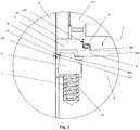
Figure 2 is a detailed view ofFig. 1 on an enlarged scale, showing the sealing device of the previous Figure. - With reference to the aforesaid Figures, a
sealing device 1 for astem 12 of avalve 10 is shown in its entirety in the section ofFig. 1 and in more detail with an enlarged scale ofFig. 2 . - Throughout the present description and in the claims, terms and expressions indicating positions and orientations such as "radial" and "axial" or "radially outer" and "radially inner" are intended to refer to the axis X of the
valve 10. - The
sealing device 1 is preferably made of steel or other alloys with high strength and anti-corrosion characteristics, such as stainless steels, nickel-based alloys or titanium-based alloys. Preferably, the device does not contain components made of plastic material or elastomer (possibly with the except of the static ring which will be described below), as the components subject to high loads have greater reliability and useful life if made of metallic material. - As shown in
Fig. 1 , thevalve 10 for subsea applications comprises amovable metal stem 12 sliding within alower valve body 14 and anupper valve body 16. Thestem 12 of the valve is made of metallic material and is preferably provided with a surface coating on its radiallyouter surface 120. The surface coating is based on very hard alloys, such as alloys based on tungsten carbide or chromium carbide, or it can be a CVD coating (an acronym for ChemicalVapourDeposition) or PVD (an acronym for PhysicalVaporDeposition) . The movement of the stem is a rotation in the example shown inFig. 1 , but the principle of operation of the sealing device, as will be explained in the following, is also equally valid if the valve stem makes another kind of movement, for example performing a linear motion. - In the
upper valve body 16 and thelower valve body 14 hydraulic orpneumatic means 18 can be provided for the valve stem actuation, as well as actuating means 20. - Finally, the valve can comprise a
closure cap 22 firmly connected to theupper valve body 16, as well as further standard components therefore not shown in the Figure or not mentioned in the present description. - As shown in
Fig. 2 , thesealing device 1 comprises ametal gasket 4 for thestem 12 of thevalve 10, shaped as a half "U". Themetal gasket 4 is positioned in radial direction between the radiallyouter surface 120 of thevalve stem 12 and the radiallyinner surface 140 of thelower valve body 14. In the axial direction, themetal gasket 4 is instead accommodated between thelower valve body 14 and aplate 5 housing an elastic element, as will be explained below. The half "U"-shaped metal gasket 4 is provided with abase portion 42, a sealing lip 44 (the radially inner side of the half "U") and with ashaped edge 46 forming afirst portion 462 of the second side of the half "U" (which is radially outer and shorter than the first side) whereas asecond portion 464 of the same shaped edge extends in a radially outer direction between thelower valve body 14 and theplate 5. - The sealing
lip 44 has a radiallyinner surface 442 and a radiallyouter surface 444, which is inclined according to the radially inner direction. The shape of the lip member is adapted to ensure that, when the contact pressure is applied to the lip member itself, it can rotate in a radially inner direction by creating an tight seal and increasing the contact area. - The
sealing lip 44 can be coated on the radiallyinner surface 442 with an alloy coating selected from the group of alloys comprising preferably tungsten carbides and chromium carbides or a PVD or CVD coating. However, also other suitable alloys can be used. Such alloy coating is advantageous due to its extreme resistance to abrasion and wear. In order to achieve a tight sealing throughout the useful life of the sealing device, both the radially inner surface of thesealing lip 44 and the radiallyouter surface 120 of thestem 12 of thevalve 10 are preferably coated with the same alloy and in any case with a suitable alloy which must resist both a chemical attack and a strong wear, by ensuring at the same time that any possible escape route and/or possibility of corrosion are excluded between the contact areas of the two mating surfaces. Thesealing lip 44 is coupled by interference against the respective surface of thestem 12 of thevalve 10 in order to reach a tight seal, which of course does not affect the movement of thestem 12 of thevalve 10. - As shown in
Fig. 2 , thesealing device 1 according to the invention, further comprises awedge ring 6. The wedge ring has the function of providing the expansion force to thesingle sealing lip 44 of themetal gasket 4. Thewedge ring 6 is made of metal, preferably selected from the group consisting of high mechanical and corrosion resistance alloys, such as stainless steels, alloys based on nickel, titanium and/or similar. - The
wedge metal ring 6 is housed inside themetal gasket 4 of thestem 12, between thesealing lip 44 and theshaped edge 46. In particular, the radiallyinner surface 62, which is placed laterally and inclined, of thewedge metal ring 6 is in contact against the radiallyouter surface 444 of thesealing lip 44. Therefore thewedge metal ring 6 forms a tight seal with themetal gasket 4 of thestem 12. - The
sealing device 1 further comprises at least oneelastic element 7 axially positioned between the wedge-metal ring 6 and aseat 52 of theplate 5. Theelastic element 7 preferably is either a helical spring or a "Belleville" spring and is made of a metal, preferably selected from the group consisting of corrosion-resistant alloys. Thesealing device 1 according to the invention is provided with at least one elastic element, although a greater number may be present depending on the needs. Theelastic element 7 applies to the wedge metal ring 6 a sufficient force so that the latter can apply a sufficient contact pressure to thesealing lip 44. - The
sealing device 1 also comprises astatic sealing ring 8, for example a metal C-shaped ring, which is axially positioned between thelower valve body 14 and theshaped edge 46 of themetal gasket 4. The function of such static gasket is to ensure a static seal against the fluid (oil or gas) . - Hence, the solution according to the present invention solves the technical problem related to the complex operation of a double metal seal, for example a metal gasket with double lip, whose synchronous operation of the two sealing lips is problematic. The technical solution according to this invention in fact simplifies the known embodiments as it uses just one metal seal against the movable element, the valve stem, and thanks to the particular conformation of the
metal gasket 4, and in particular of itsshaped edge 46, a second static seal is more than sufficient for a simple elastomeric sealing ring. - The
sealing device 1 of the stem of thevalve 12 of the present invention can also comprise ananti-rotation pin 9, which is fixed to theplate 5 and to thelower valve body 14. Theanti-rotation pin 9 keeps thesealing device 1 in position and prevents the rotation of the same. The shape of thepin 9 is preferably cylindrical and advantageously, thepin 9 is positioned to one half within thelower valve body 14 and to the other half inside of theplate 5 of thegasket 4. - In addition to the embodiments of the invention, as previously described, it is to be understood that there are numerous further variants. It must also be understood that said embodiments are only exemplary and limit neither the subject of the invention nor its applications, nor its possible configurations. On the contrary, although the above description makes it possible to the skilled technician to implement the present invention at least according to one of its exemplary configuration, it should be understood that numerous variations are conceivable of the components described, without for this reason escaping from the subject of the invention, as defined in the appended claims.
Claims (11)
- Sealing device (1) for a stem (12) of a valve (10) comprising:- a metal gasket (4) for the valve (10) stem (12), provided with a single sealing lip (44), forming a radially inner side of the metal gasket which has a radially inner surface (442) and a radially outer surface (444), inclined along the radially inner direction,- a wedge metal ring (6) positioned inside of the metal gasket (4),- an elastic element (7) configured to cooperate with said wedge metal ring (6), said elastic element providing the wedge metal ring with an elastic load,- a static sealing ring (8),the sealing device being characterized in that the elastic element (7) is configured for applying a force to the wedge metal ring (6) such that said wedge metal ring (6) applies a contact pressure to the single sealing lip (44) of the metal gasket (4) and in that the metal gasket (4) is further provided with a base portion (42) and a shaped edge (46) establishing for a first portion (462) a radially outer side of the metal gasket, while a second portion (464) of said shaped edge (46) extends in a radially outer direction.
- Sealing device (1) according to claim 1, characterized in that the single sealing lip (44) is configured so that when exposed to the contact pressure generated from the wedge metal ring (6) the sealing lip rotates in the radially inner direction to create a first seal surface on the stem (12) of the valve (10).
- Sealing device (1) according to any of the preceding claims, characterized in that the wedge metal ring (6) is housed inside the metal gasket (4) between the sealing lip (44) and the shaped edge (46).
- Sealing device (1) according to claim 3, characterized in that a radially inner surface (62) of the wedge metal ring (6) is lateral and inclined and in contact against the radially outer surface (444) of the sealing lip (44).
- Sealing device (1) according to any of the preceding claims, characterized in that said elastic element (7) is positioned axially between the wedge metal ring (6) and a seat (52) of a plate (5).
- Sealing device (1) according to claim 5, characterized in that the elastic element (7) is a helical spring or a "Belleville" spring.
- Sealing device (1) according to any of the preceding claims, characterized in that said static sealing ring (8), is configured to be maintained by the shaped edge (46) of the metal gasket (4) in contact with the valve (10), generating a second sealing surface.
- Sealing device (1) according to any of the claims from 5 to 7, characterized in that it comprises an anti-rotation pin (9) configured to rotationally connect a plate (5) of the sealing device (1) to the valve (10).
- A valve (10) comprising a mobile and metal stem (12) that rotates and / or flows within a lower valve body (14) and an upper valve body (16) characterized in that the valve (10) includes a sealing device (1) according to one of the preceding claims.
- A valve (10) according to claim 9, characterized by the fact that the metal gasket (4) for the stem (12) is positioned in a radial direction between a radially outer surface (120) of the stem (12) of the valve (10) and a radially inner surface (140) of the lower valve body (14).
- A valve (10) according to claim 9 or 10, characterized by the fact that the metal gasket (4) for the stem (12) is positioned in the axial direction between the lower valve body (14) and a plate (5) of the sealing device (1).
Applications Claiming Priority (1)
| Application Number | Priority Date | Filing Date | Title |
|---|---|---|---|
| ITUA2016A002716A ITUA20162716A1 (en) | 2016-04-19 | 2016-04-19 | HOLDING DEVICE FOR THE STEM OF A VALVE |
Publications (2)
| Publication Number | Publication Date |
|---|---|
| EP3236116A1 EP3236116A1 (en) | 2017-10-25 |
| EP3236116B1 true EP3236116B1 (en) | 2020-06-03 |
Family
ID=56555602
Family Applications (1)
| Application Number | Title | Priority Date | Filing Date |
|---|---|---|---|
| EP17166440.2A Not-in-force EP3236116B1 (en) | 2016-04-19 | 2017-04-13 | Sealing device for a stem of a valve |
Country Status (3)
| Country | Link |
|---|---|
| US (1) | US10458571B2 (en) |
| EP (1) | EP3236116B1 (en) |
| IT (1) | ITUA20162716A1 (en) |
Families Citing this family (3)
| Publication number | Priority date | Publication date | Assignee | Title |
|---|---|---|---|---|
| JP7014749B2 (en) * | 2019-03-28 | 2022-02-01 | 株式会社鷺宮製作所 | Temperature expansion valve and refrigeration cycle system |
| CN112212008B (en) * | 2020-09-03 | 2022-07-15 | 广州机械科学研究院有限公司 | Pressure self-adaptive rotary sealing device |
| US11608752B2 (en) * | 2021-02-22 | 2023-03-21 | General Electric Company | Sealing apparatus for an axial flow turbomachine |
Family Cites Families (8)
| Publication number | Priority date | Publication date | Assignee | Title |
|---|---|---|---|---|
| US954195A (en) * | 1909-09-02 | 1910-04-05 | William H Law | Metallic packing. |
| US4899980A (en) * | 1989-01-10 | 1990-02-13 | Kemp Development Corporation | Ball valve |
| DE4110700A1 (en) * | 1991-04-03 | 1992-10-08 | Wunsch Eckart | SEALING ARRANGEMENT |
| DE4225142C2 (en) * | 1992-07-30 | 1996-07-18 | Daimler Benz Aerospace Ag | Device for sealing metallic cylindrical bodies |
| JP3866882B2 (en) * | 1999-06-30 | 2007-01-10 | ニチアス株式会社 | Metal C-ring gasket and metal gasket manufacturing method |
| JP4201536B2 (en) * | 2002-07-03 | 2008-12-24 | サーパス工業株式会社 | Flow control device |
| DK1819956T3 (en) | 2004-11-05 | 2013-01-14 | Petrolvalves Usa | Metal valve spindle seal and sealing system |
| US20070175627A1 (en) * | 2005-11-15 | 2007-08-02 | Pippert Frederick B | Stuffing box assembly and sealing assembly for use therein |
-
2016
- 2016-04-19 IT ITUA2016A002716A patent/ITUA20162716A1/en unknown
-
2017
- 2017-04-13 EP EP17166440.2A patent/EP3236116B1/en not_active Not-in-force
- 2017-04-18 US US15/489,961 patent/US10458571B2/en not_active Expired - Fee Related
Non-Patent Citations (1)
| Title |
|---|
| None * |
Also Published As
| Publication number | Publication date |
|---|---|
| US20170299087A1 (en) | 2017-10-19 |
| EP3236116A1 (en) | 2017-10-25 |
| ITUA20162716A1 (en) | 2017-10-19 |
| US10458571B2 (en) | 2019-10-29 |
Similar Documents
| Publication | Publication Date | Title |
|---|---|---|
| US7428912B2 (en) | Metal valve stem and sealing system | |
| US3894718A (en) | Ball valve | |
| EP2238380B1 (en) | Energized composite metal to metal seal | |
| US5803431A (en) | Shearing gate valve | |
| US8403296B2 (en) | Metal seat seal with flexible sealing edge | |
| US10458571B2 (en) | Sealing device for a stem of a valve | |
| EP3279529A1 (en) | Flexible seat ball valve | |
| US5259590A (en) | Valve seat for high temperature valve | |
| US9879789B2 (en) | Ball valve seal | |
| CN102094987A (en) | Ultrahigh pressure flat plate gate valve | |
| EP1034391B1 (en) | Ball valve | |
| US20070138429A1 (en) | Flexible seals for process control valves | |
| EP1925865A1 (en) | Metal stem seal | |
| GB2193296A (en) | Butterfly valve | |
| US20050012063A1 (en) | Flexible metal sealing lip | |
| US12584560B2 (en) | Gate valves with dynamic skirts and multiple energizers | |
| KR102765746B1 (en) | Plug valve having a disk-shaped buffer member corresponding to the contraction and expansion of the collar | |
| US20250283534A1 (en) | Metallic Dynamic Seal | |
| NO344443B1 (en) | A metal-to-metal stem seal system | |
| CZ31634U1 (en) | A metal seal for closing valves |
Legal Events
| Date | Code | Title | Description |
|---|---|---|---|
| PUAI | Public reference made under article 153(3) epc to a published international application that has entered the european phase |
Free format text: ORIGINAL CODE: 0009012 |
|
| STAA | Information on the status of an ep patent application or granted ep patent |
Free format text: STATUS: THE APPLICATION HAS BEEN PUBLISHED |
|
| AK | Designated contracting states |
Kind code of ref document: A1 Designated state(s): AL AT BE BG CH CY CZ DE DK EE ES FI FR GB GR HR HU IE IS IT LI LT LU LV MC MK MT NL NO PL PT RO RS SE SI SK SM TR |
|
| AX | Request for extension of the european patent |
Extension state: BA ME |
|
| RIN1 | Information on inventor provided before grant (corrected) |
Inventor name: VAGO, ANTONELLO Inventor name: ZUCCARELLI, DINO |
|
| STAA | Information on the status of an ep patent application or granted ep patent |
Free format text: STATUS: REQUEST FOR EXAMINATION WAS MADE |
|
| 17P | Request for examination filed |
Effective date: 20180412 |
|
| RBV | Designated contracting states (corrected) |
Designated state(s): AL AT BE BG CH CY CZ DE DK EE ES FI FR GB GR HR HU IE IS IT LI LT LU LV MC MK MT NL NO PL PT RO RS SE SI SK SM TR |
|
| STAA | Information on the status of an ep patent application or granted ep patent |
Free format text: STATUS: EXAMINATION IS IN PROGRESS |
|
| 17Q | First examination report despatched |
Effective date: 20190226 |
|
| GRAP | Despatch of communication of intention to grant a patent |
Free format text: ORIGINAL CODE: EPIDOSNIGR1 |
|
| STAA | Information on the status of an ep patent application or granted ep patent |
Free format text: STATUS: GRANT OF PATENT IS INTENDED |
|
| INTG | Intention to grant announced |
Effective date: 20200103 |
|
| GRAS | Grant fee paid |
Free format text: ORIGINAL CODE: EPIDOSNIGR3 |
|
| GRAA | (expected) grant |
Free format text: ORIGINAL CODE: 0009210 |
|
| STAA | Information on the status of an ep patent application or granted ep patent |
Free format text: STATUS: THE PATENT HAS BEEN GRANTED |
|
| AK | Designated contracting states |
Kind code of ref document: B1 Designated state(s): AL AT BE BG CH CY CZ DE DK EE ES FI FR GB GR HR HU IE IS IT LI LT LU LV MC MK MT NL NO PL PT RO RS SE SI SK SM TR |
|
| REG | Reference to a national code |
Ref country code: GB Ref legal event code: FG4D |
|
| REG | Reference to a national code |
Ref country code: CH Ref legal event code: EP Ref country code: AT Ref legal event code: REF Ref document number: 1277352 Country of ref document: AT Kind code of ref document: T Effective date: 20200615 |
|
| REG | Reference to a national code |
Ref country code: DE Ref legal event code: R096 Ref document number: 602017017529 Country of ref document: DE |
|
| REG | Reference to a national code |
Ref country code: NO Ref legal event code: T2 Effective date: 20200603 |
|
| REG | Reference to a national code |
Ref country code: LT Ref legal event code: MG4D |
|
| PG25 | Lapsed in a contracting state [announced via postgrant information from national office to epo] |
Ref country code: LT Free format text: LAPSE BECAUSE OF FAILURE TO SUBMIT A TRANSLATION OF THE DESCRIPTION OR TO PAY THE FEE WITHIN THE PRESCRIBED TIME-LIMIT Effective date: 20200603 Ref country code: FI Free format text: LAPSE BECAUSE OF FAILURE TO SUBMIT A TRANSLATION OF THE DESCRIPTION OR TO PAY THE FEE WITHIN THE PRESCRIBED TIME-LIMIT Effective date: 20200603 Ref country code: GR Free format text: LAPSE BECAUSE OF FAILURE TO SUBMIT A TRANSLATION OF THE DESCRIPTION OR TO PAY THE FEE WITHIN THE PRESCRIBED TIME-LIMIT Effective date: 20200904 Ref country code: SE Free format text: LAPSE BECAUSE OF FAILURE TO SUBMIT A TRANSLATION OF THE DESCRIPTION OR TO PAY THE FEE WITHIN THE PRESCRIBED TIME-LIMIT Effective date: 20200603 |
|
| REG | Reference to a national code |
Ref country code: NL Ref legal event code: MP Effective date: 20200603 |
|
| PG25 | Lapsed in a contracting state [announced via postgrant information from national office to epo] |
Ref country code: HR Free format text: LAPSE BECAUSE OF FAILURE TO SUBMIT A TRANSLATION OF THE DESCRIPTION OR TO PAY THE FEE WITHIN THE PRESCRIBED TIME-LIMIT Effective date: 20200603 Ref country code: RS Free format text: LAPSE BECAUSE OF FAILURE TO SUBMIT A TRANSLATION OF THE DESCRIPTION OR TO PAY THE FEE WITHIN THE PRESCRIBED TIME-LIMIT Effective date: 20200603 Ref country code: BG Free format text: LAPSE BECAUSE OF FAILURE TO SUBMIT A TRANSLATION OF THE DESCRIPTION OR TO PAY THE FEE WITHIN THE PRESCRIBED TIME-LIMIT Effective date: 20200903 Ref country code: LV Free format text: LAPSE BECAUSE OF FAILURE TO SUBMIT A TRANSLATION OF THE DESCRIPTION OR TO PAY THE FEE WITHIN THE PRESCRIBED TIME-LIMIT Effective date: 20200603 |
|
| REG | Reference to a national code |
Ref country code: AT Ref legal event code: MK05 Ref document number: 1277352 Country of ref document: AT Kind code of ref document: T Effective date: 20200603 |
|
| PG25 | Lapsed in a contracting state [announced via postgrant information from national office to epo] |
Ref country code: AL Free format text: LAPSE BECAUSE OF FAILURE TO SUBMIT A TRANSLATION OF THE DESCRIPTION OR TO PAY THE FEE WITHIN THE PRESCRIBED TIME-LIMIT Effective date: 20200603 Ref country code: NL Free format text: LAPSE BECAUSE OF FAILURE TO SUBMIT A TRANSLATION OF THE DESCRIPTION OR TO PAY THE FEE WITHIN THE PRESCRIBED TIME-LIMIT Effective date: 20200603 |
|
| PG25 | Lapsed in a contracting state [announced via postgrant information from national office to epo] |
Ref country code: AT Free format text: LAPSE BECAUSE OF FAILURE TO SUBMIT A TRANSLATION OF THE DESCRIPTION OR TO PAY THE FEE WITHIN THE PRESCRIBED TIME-LIMIT Effective date: 20200603 Ref country code: EE Free format text: LAPSE BECAUSE OF FAILURE TO SUBMIT A TRANSLATION OF THE DESCRIPTION OR TO PAY THE FEE WITHIN THE PRESCRIBED TIME-LIMIT Effective date: 20200603 Ref country code: SM Free format text: LAPSE BECAUSE OF FAILURE TO SUBMIT A TRANSLATION OF THE DESCRIPTION OR TO PAY THE FEE WITHIN THE PRESCRIBED TIME-LIMIT Effective date: 20200603 Ref country code: RO Free format text: LAPSE BECAUSE OF FAILURE TO SUBMIT A TRANSLATION OF THE DESCRIPTION OR TO PAY THE FEE WITHIN THE PRESCRIBED TIME-LIMIT Effective date: 20200603 Ref country code: ES Free format text: LAPSE BECAUSE OF FAILURE TO SUBMIT A TRANSLATION OF THE DESCRIPTION OR TO PAY THE FEE WITHIN THE PRESCRIBED TIME-LIMIT Effective date: 20200603 Ref country code: CZ Free format text: LAPSE BECAUSE OF FAILURE TO SUBMIT A TRANSLATION OF THE DESCRIPTION OR TO PAY THE FEE WITHIN THE PRESCRIBED TIME-LIMIT Effective date: 20200603 Ref country code: PT Free format text: LAPSE BECAUSE OF FAILURE TO SUBMIT A TRANSLATION OF THE DESCRIPTION OR TO PAY THE FEE WITHIN THE PRESCRIBED TIME-LIMIT Effective date: 20201006 |
|
| PG25 | Lapsed in a contracting state [announced via postgrant information from national office to epo] |
Ref country code: PL Free format text: LAPSE BECAUSE OF FAILURE TO SUBMIT A TRANSLATION OF THE DESCRIPTION OR TO PAY THE FEE WITHIN THE PRESCRIBED TIME-LIMIT Effective date: 20200603 Ref country code: SK Free format text: LAPSE BECAUSE OF FAILURE TO SUBMIT A TRANSLATION OF THE DESCRIPTION OR TO PAY THE FEE WITHIN THE PRESCRIBED TIME-LIMIT Effective date: 20200603 Ref country code: IS Free format text: LAPSE BECAUSE OF FAILURE TO SUBMIT A TRANSLATION OF THE DESCRIPTION OR TO PAY THE FEE WITHIN THE PRESCRIBED TIME-LIMIT Effective date: 20201003 |
|
| REG | Reference to a national code |
Ref country code: DE Ref legal event code: R097 Ref document number: 602017017529 Country of ref document: DE |
|
| PLBE | No opposition filed within time limit |
Free format text: ORIGINAL CODE: 0009261 |
|
| STAA | Information on the status of an ep patent application or granted ep patent |
Free format text: STATUS: NO OPPOSITION FILED WITHIN TIME LIMIT |
|
| PG25 | Lapsed in a contracting state [announced via postgrant information from national office to epo] |
Ref country code: DK Free format text: LAPSE BECAUSE OF FAILURE TO SUBMIT A TRANSLATION OF THE DESCRIPTION OR TO PAY THE FEE WITHIN THE PRESCRIBED TIME-LIMIT Effective date: 20200603 |
|
| PGFP | Annual fee paid to national office [announced via postgrant information from national office to epo] |
Ref country code: IT Payment date: 20210318 Year of fee payment: 5 Ref country code: LU Payment date: 20210319 Year of fee payment: 5 Ref country code: MC Payment date: 20210322 Year of fee payment: 5 Ref country code: NO Payment date: 20210323 Year of fee payment: 5 Ref country code: FR Payment date: 20210319 Year of fee payment: 5 Ref country code: IE Payment date: 20210319 Year of fee payment: 5 Ref country code: CH Payment date: 20210323 Year of fee payment: 5 |
|
| 26N | No opposition filed |
Effective date: 20210304 |
|
| PG25 | Lapsed in a contracting state [announced via postgrant information from national office to epo] |
Ref country code: SI Free format text: LAPSE BECAUSE OF FAILURE TO SUBMIT A TRANSLATION OF THE DESCRIPTION OR TO PAY THE FEE WITHIN THE PRESCRIBED TIME-LIMIT Effective date: 20200603 |
|
| PGFP | Annual fee paid to national office [announced via postgrant information from national office to epo] |
Ref country code: GB Payment date: 20210322 Year of fee payment: 5 Ref country code: BE Payment date: 20210319 Year of fee payment: 5 |
|
| PGFP | Annual fee paid to national office [announced via postgrant information from national office to epo] |
Ref country code: DE Payment date: 20210319 Year of fee payment: 5 |
|
| REG | Reference to a national code |
Ref country code: DE Ref legal event code: R119 Ref document number: 602017017529 Country of ref document: DE |
|
| REG | Reference to a national code |
Ref country code: NO Ref legal event code: MMEP |
|
| REG | Reference to a national code |
Ref country code: CH Ref legal event code: PL |
|
| GBPC | Gb: european patent ceased through non-payment of renewal fee |
Effective date: 20220413 |
|
| REG | Reference to a national code |
Ref country code: BE Ref legal event code: MM Effective date: 20220430 |
|
| PG25 | Lapsed in a contracting state [announced via postgrant information from national office to epo] |
Ref country code: NO Free format text: LAPSE BECAUSE OF NON-PAYMENT OF DUE FEES Effective date: 20220430 Ref country code: MC Free format text: LAPSE BECAUSE OF NON-PAYMENT OF DUE FEES Effective date: 20220502 Ref country code: LU Free format text: LAPSE BECAUSE OF NON-PAYMENT OF DUE FEES Effective date: 20220413 Ref country code: LI Free format text: LAPSE BECAUSE OF NON-PAYMENT OF DUE FEES Effective date: 20220430 Ref country code: GB Free format text: LAPSE BECAUSE OF NON-PAYMENT OF DUE FEES Effective date: 20220413 Ref country code: FR Free format text: LAPSE BECAUSE OF NON-PAYMENT OF DUE FEES Effective date: 20220430 Ref country code: DE Free format text: LAPSE BECAUSE OF NON-PAYMENT OF DUE FEES Effective date: 20221103 Ref country code: CH Free format text: LAPSE BECAUSE OF NON-PAYMENT OF DUE FEES Effective date: 20220430 |
|
| PG25 | Lapsed in a contracting state [announced via postgrant information from national office to epo] |
Ref country code: BE Free format text: LAPSE BECAUSE OF NON-PAYMENT OF DUE FEES Effective date: 20220430 |
|
| PG25 | Lapsed in a contracting state [announced via postgrant information from national office to epo] |
Ref country code: IE Free format text: LAPSE BECAUSE OF NON-PAYMENT OF DUE FEES Effective date: 20220413 |
|
| PG25 | Lapsed in a contracting state [announced via postgrant information from national office to epo] |
Ref country code: IT Free format text: LAPSE BECAUSE OF NON-PAYMENT OF DUE FEES Effective date: 20220413 Ref country code: HU Free format text: LAPSE BECAUSE OF FAILURE TO SUBMIT A TRANSLATION OF THE DESCRIPTION OR TO PAY THE FEE WITHIN THE PRESCRIBED TIME-LIMIT; INVALID AB INITIO Effective date: 20170413 |
|
| PG25 | Lapsed in a contracting state [announced via postgrant information from national office to epo] |
Ref country code: CY Free format text: LAPSE BECAUSE OF FAILURE TO SUBMIT A TRANSLATION OF THE DESCRIPTION OR TO PAY THE FEE WITHIN THE PRESCRIBED TIME-LIMIT Effective date: 20200603 |
|
| PG25 | Lapsed in a contracting state [announced via postgrant information from national office to epo] |
Ref country code: MK Free format text: LAPSE BECAUSE OF FAILURE TO SUBMIT A TRANSLATION OF THE DESCRIPTION OR TO PAY THE FEE WITHIN THE PRESCRIBED TIME-LIMIT Effective date: 20200603 |
|
| PG25 | Lapsed in a contracting state [announced via postgrant information from national office to epo] |
Ref country code: MT Free format text: LAPSE BECAUSE OF FAILURE TO SUBMIT A TRANSLATION OF THE DESCRIPTION OR TO PAY THE FEE WITHIN THE PRESCRIBED TIME-LIMIT Effective date: 20200603 |
|
| PG25 | Lapsed in a contracting state [announced via postgrant information from national office to epo] |
Ref country code: TR Free format text: LAPSE BECAUSE OF FAILURE TO SUBMIT A TRANSLATION OF THE DESCRIPTION OR TO PAY THE FEE WITHIN THE PRESCRIBED TIME-LIMIT Effective date: 20200603 |