EP3236109B1 - Gear change device for a motor vehicle and method for manufacture thereof - Google Patents
Gear change device for a motor vehicle and method for manufacture thereof Download PDFInfo
- Publication number
- EP3236109B1 EP3236109B1 EP16166438.8A EP16166438A EP3236109B1 EP 3236109 B1 EP3236109 B1 EP 3236109B1 EP 16166438 A EP16166438 A EP 16166438A EP 3236109 B1 EP3236109 B1 EP 3236109B1
- Authority
- EP
- European Patent Office
- Prior art keywords
- gear
- shaft
- primary
- gear change
- end portion
- Prior art date
- Legal status (The legal status is an assumption and is not a legal conclusion. Google has not performed a legal analysis and makes no representation as to the accuracy of the status listed.)
- Active
Links
Images



Classifications
-
- F—MECHANICAL ENGINEERING; LIGHTING; HEATING; WEAPONS; BLASTING
- F16—ENGINEERING ELEMENTS AND UNITS; GENERAL MEASURES FOR PRODUCING AND MAINTAINING EFFECTIVE FUNCTIONING OF MACHINES OR INSTALLATIONS; THERMAL INSULATION IN GENERAL
- F16H—GEARING
- F16H57/00—General details of gearing
- F16H57/02—Gearboxes; Mounting gearing therein
- F16H57/021—Shaft support structures, e.g. partition walls, bearing eyes, casing walls or covers with bearings
-
- F—MECHANICAL ENGINEERING; LIGHTING; HEATING; WEAPONS; BLASTING
- F16—ENGINEERING ELEMENTS AND UNITS; GENERAL MEASURES FOR PRODUCING AND MAINTAINING EFFECTIVE FUNCTIONING OF MACHINES OR INSTALLATIONS; THERMAL INSULATION IN GENERAL
- F16H—GEARING
- F16H57/00—General details of gearing
- F16H57/02—Gearboxes; Mounting gearing therein
- F16H57/031—Gearboxes; Mounting gearing therein characterised by covers or lids for gearboxes
-
- F—MECHANICAL ENGINEERING; LIGHTING; HEATING; WEAPONS; BLASTING
- F16—ENGINEERING ELEMENTS AND UNITS; GENERAL MEASURES FOR PRODUCING AND MAINTAINING EFFECTIVE FUNCTIONING OF MACHINES OR INSTALLATIONS; THERMAL INSULATION IN GENERAL
- F16H—GEARING
- F16H57/00—General details of gearing
- F16H57/04—Features relating to lubrication or cooling or heating
- F16H57/042—Guidance of lubricant
- F16H57/0421—Guidance of lubricant on or within the casing, e.g. shields or baffles for collecting lubricant, tubes, pipes, grooves, channels or the like
- F16H57/0426—Means for guiding lubricant into an axial channel of a shaft
-
- F—MECHANICAL ENGINEERING; LIGHTING; HEATING; WEAPONS; BLASTING
- F16—ENGINEERING ELEMENTS AND UNITS; GENERAL MEASURES FOR PRODUCING AND MAINTAINING EFFECTIVE FUNCTIONING OF MACHINES OR INSTALLATIONS; THERMAL INSULATION IN GENERAL
- F16H—GEARING
- F16H57/00—General details of gearing
- F16H57/02—Gearboxes; Mounting gearing therein
- F16H57/021—Shaft support structures, e.g. partition walls, bearing eyes, casing walls or covers with bearings
- F16H2057/0216—Intermediate shaft supports, e.g. by using a partition wall
-
- F—MECHANICAL ENGINEERING; LIGHTING; HEATING; WEAPONS; BLASTING
- F16—ENGINEERING ELEMENTS AND UNITS; GENERAL MEASURES FOR PRODUCING AND MAINTAINING EFFECTIVE FUNCTIONING OF MACHINES OR INSTALLATIONS; THERMAL INSULATION IN GENERAL
- F16H—GEARING
- F16H2200/00—Transmissions for multiple ratios
- F16H2200/003—Transmissions for multiple ratios characterised by the number of forward speeds
- F16H2200/0047—Transmissions for multiple ratios characterised by the number of forward speeds the gear ratios comprising five forward speeds
-
- F—MECHANICAL ENGINEERING; LIGHTING; HEATING; WEAPONS; BLASTING
- F16—ENGINEERING ELEMENTS AND UNITS; GENERAL MEASURES FOR PRODUCING AND MAINTAINING EFFECTIVE FUNCTIONING OF MACHINES OR INSTALLATIONS; THERMAL INSULATION IN GENERAL
- F16H—GEARING
- F16H2200/00—Transmissions for multiple ratios
- F16H2200/003—Transmissions for multiple ratios characterised by the number of forward speeds
- F16H2200/0052—Transmissions for multiple ratios characterised by the number of forward speeds the gear ratios comprising six forward speeds
-
- F—MECHANICAL ENGINEERING; LIGHTING; HEATING; WEAPONS; BLASTING
- F16—ENGINEERING ELEMENTS AND UNITS; GENERAL MEASURES FOR PRODUCING AND MAINTAINING EFFECTIVE FUNCTIONING OF MACHINES OR INSTALLATIONS; THERMAL INSULATION IN GENERAL
- F16H—GEARING
- F16H3/00—Toothed gearings for conveying rotary motion with variable gear ratio or for reversing rotary motion
- F16H3/02—Toothed gearings for conveying rotary motion with variable gear ratio or for reversing rotary motion without gears having orbital motion
- F16H3/08—Toothed gearings for conveying rotary motion with variable gear ratio or for reversing rotary motion without gears having orbital motion exclusively or essentially with continuously meshing gears, that can be disengaged from their shafts
- F16H3/087—Toothed gearings for conveying rotary motion with variable gear ratio or for reversing rotary motion without gears having orbital motion exclusively or essentially with continuously meshing gears, that can be disengaged from their shafts characterised by the disposition of the gears
- F16H3/089—Toothed gearings for conveying rotary motion with variable gear ratio or for reversing rotary motion without gears having orbital motion exclusively or essentially with continuously meshing gears, that can be disengaged from their shafts characterised by the disposition of the gears all of the meshing gears being supported by a pair of parallel shafts, one being the input shaft and the other the output shaft, there being no countershaft involved
Definitions
- the present invention relates to gear change devices for motor vehicles of the type including:
- Figure 1 is a schematic cross-sectional view of a gear change device 1, with six gears, of the conventional type referred to above.
- the gear change device 1 comprises a gear change casing 2, for example made of aluminium, which supports a primary shaft P and a secondary shaft S in rotation about respective axes 3 and 4.
- the primary shaft P is rotatably mounted within the gear change casing 2 by means of a first rolling bearing C1 on the side facing the engine (not illustrated) and a second rolling bearing C2 located at the opposite end of the gear change casing 2.
- the secondary shaft S is rotatably supported by the gear change casing 2 by means of a rolling bearing C3 at the end of the gear change casing 2 facing the engine and by means of a bearing C4 at the opposite end of the gear change casing.
- Figure 1 also partially shows the bell 5 of the clutch used for connecting the primary shaft P to the engine shaft (not illustrated).
- the primary shaft P and the secondary shaft S have, on the side opposite to the engine, end portions P1 and S1 that extend beyond the bearings C2 and C4, within a portion 2A of gear change casing rigidly connected to the main body of the gear change casing 2.
- the portion 2A of gear change casing supports directly in rotation the aforesaid end portions P1, S1 of the primary and secondary shafts P, S by means of respective rolling bearings C5, C6.
- Figure 1 shows an example of a conventional gear change with six gears in which the primary and secondary shafts P, S carry the same number of gear pairs R11, R12; R21, R22; R31, R32; R41, R42; R51, R52; and R61, R62, which mesh with one another.
- gear pairs R11, R12; R21, R22; R31, R32; R41, R42; R51, R52; and R61, R62 which mesh with one another.
- the gears R11, R21 are rigidly connected to the primary shaft P and mesh with gears R12, R22 that are mounted freely rotating on the secondary shaft S.
- the gears R32, R42, R52, R62 are all rigidly connected to the secondary shaft S and mesh with gears R31, R41, R51, R61 mounted freely rotating on the primary shaft P.
- Each of these engagement devices includes a sleeve, which is to be driven by a respective fork (not visible in the drawing) controlled by a gear change control device.
- Each engagement device can be displaced axially starting from a neutral central position in one direction or in the other for connecting a respective gear in rotation to the shaft on which it is mounted.
- the engagement device F1 has two opposite operative positions in which it can be displaced selectively for connecting the gear R31 or the gear R41 in rotation to the primary shaft P.
- the engagement device F2 is designed to connect the gear R51 or the gear R61 in rotation to the primary shaft P.
- the engagement device F3 is designed to connect the gear R12 or the gear R22, respectively, in rotation to the secondary shaft S. In each gear condition, just one of the engagement devices F1, F2, F3 is located in an active position thereof, in such a way that a transmission ratio is implemented corresponding to the gear pair thus selected.
- the two gear pairs R51, R52 and R61, R62 are carried by two end portions P1 and S1 of the primary and secondary shafts P, S that project beyond the rolling bearings C2, C4.
- the end portion P1 of the primary shaft P also carries the engagement device F2.
- the end portions P1, S1 extend within the portion 2A of the gear change casing 2, which is screwed to the end of the main body of the gear change casing 2 on the side opposite to the engine.
- the portion 2A of the gear change casing has an end wall 2A1, mounted within which are the rolling bearings C5, C6 that support in rotation the terminal parts of the end portions P1, S1.
- Figure 2 shows the end portion of the gear change in the five-gear version.
- the gear pair R61, R62 is omitted, as likewise omitted are the rolling bearings C5, C6.
- the engagement device associated to the end portion P1' is moreover a device F2' modified with respect to the engagement device F2 of Figure 1 in so far as has just one active position in which it connects the gear R51 in rotation to the primary shaft P'.
- a gear change device according to the preamble of claim 1 is known from DE 40 41 899 A1.
- the object of the present invention is to provide a gear change device for motor vehicles having an architecture such as to enable production of different versions of gear change, with different numbers of gears, by means of a simple and efficient production line.
- a further object of the invention is to provide a gear change device that is suited to being produced in different versions, and in which each version of gear change has a simple and low-cost structure.
- a further object of the invention is to provide a gear change device the parts of which can be assembled in a simple and at the same time precise way so as to ensure proper and reliable operation of the gear change device.
- the subject of the present invention is a gear change device having all the characteristics of claim 1.
- the main advantage deriving from the structure and arrangement described above lies in the fact that different versions of the gear change device, characterized by a different number of gears, can be assembled on one and the same production line, in a simple and efficient way.
- the shaft-extension elements are not mounted when the aim is to obtain a gear change device with n gears, whereas they are mounted when the aim is to obtain a gear change device with at least n+1 gears.
- the first end portion and the first shaft-extension element define together a continuous cylindrical surface, interference-fitted on which is a cylindrical bushing that rotatably supports the third gear via a rolling bearing.
- the second gear and the fourth gear have adjacent hubs that together define a cylindrical surface, interference-fitted on which is a cylindrical bushing.
- Figures 3 and 4 of the annexed drawings show schematic sections in the assembled condition and in an exploded condition, respectively, of the end portion of the gear change device of Figure 1 , modified according to the teachings of the present invention, to provide a gear change device with six gears.
- the main characteristic of the gear change device according to the invention lies in the fact that, instead of using primary and secondary shafts of different lengths to obtain gear change devices with different numbers of gears, a modular structure is adopted for each of the aforesaid shafts, which envisages that to the end portion of the primary and secondary shafts, on the side opposite to the engine, a shaft-extension element is coupled in the case where it is desired to obtain the version of gear change with a higher number of gears.
- both the primary shaft P and the secondary shaft S have a composite modular structure, including two shaft-extension elements E1 and E2 that are coupled to the end portions P1, S1 of the primary and secondary shafts P, S.
- the shaft-extension element E1 has a tubular body, with an end of larger diameter 101, extending from which is an intermediate cylindrical body 102, from which there in turn extends a cylindrical shank 103 of smaller diameter.
- the cylindrical shank 103 has its outer surface threaded for engagement by screwing within a threaded axial hole 104 formed in the primary shaft P starting from its end surface 105.
- the shaft-extension element E2 has an end of larger diameter 201, an intermediate cylindrical portion 202, and an end shank 203 of smaller diameter, having its outer surface threaded, for engagement by screwing within a threaded axial hole 204 made starting from the end surface 205 of the secondary shaft S.
- the ends 101, 201 of the shaft-extension elements E1, E2 are rotatably supported within the portion 2A of the gear change casing by means of the rolling bearings C5, C6.
- a bushing B1 that supports the gear R61 in rotation by means of a rolling bearing. Mounting is obtained by interference fit.
- the coupling surfaces between the bushing B1, the end portion P1, and the portion 101 of the shaft-extension element E1 are machined with a precision sufficient to ensure coaxiality of the end portion P1 of the primary shaft P and of the shaft-extension element E1, within a strict tolerance.
- the intermediate portion 202 of the shaft-extension element E2 and the end portion S1 of the secondary shaft S are adjacent to one another in the coupled condition and, since they have the same diameter, they define a continuous cylindrical surface.
- the coaxiality between the secondary shaft S and the shaft-extension element E2 is ensured by the interference fit of a cylindrical bushing B2 on adjacent hubs H1, H2 of the two gears R52, R62.
- the gear R52 is rigidly connected to the end portion S1 of the secondary shaft S, according to the prior art.
- the gear R62 is rigidly connected, by interference fit, on the intermediate portion 202 of the shaft-extension element E2.
- the bushing B2 is interference-fitted on the hubs H1, H2, and the coupling surfaces are machined with a precision sufficient to ensure that the coaxiality between the end portion S1 of the secondary shaft S and the shaft-extension element E2 is guaranteed within a strict tolerance.
- the shaft-extension elements E1, E2 are eliminated, as shown in Figure 5 , so as not to require provision of two different primary and secondary shafts P, S.
- the two rolling bearings C5, C6 are eliminated.
- the axial holes 104, 204 are covered by two caps 106, 206 screwed within them, having heads resting against the end surfaces of the primary and secondary shafts P, S.
- the engagement device F1 is replaced by an engagement device F1' having just one operating position, for connecting in rotation the gear R51 to the end portion P1 of the primary shaft P.
- the gear change device has a structure devised according to criteria of modularity, which enables production of gear changes with different numbers of gears on a single production line, with advantages of simplification of production and higher efficiency.
- the reference T designates a single production line, which includes a succession of assembly stations S10, S20, S30, etc., where successive operations of assembly that are common to the two different versions of gear change device (for example, a six-gear version and a five-gear version) are carried out.
- the line splits up into two branches and hence proceeds towards a station S6, for assembly for example of the six-gear version, or else towards a station S5, for assembly of the five-gear version.
- the shaft-extension elements E1, E2 are coupled to the primary and secondary shafts P, S, whereas in the station S5 this operation is not carried out.
- the final operations are carried out necessary to obtain, for example, the six-gear device of Figure 3 or the five-gear device of Figure 5 , respectively.
- the line remains single and includes different workstations for carrying out assembly of different versions of the gear change.
- the structure of the gear change device as described above facilitates and simplifies the operations of assembly and at the same time ensures the precision of assembly that is necessary in order to obtain proper and reliable operation of the gear change device.
Landscapes
- Engineering & Computer Science (AREA)
- General Engineering & Computer Science (AREA)
- Mechanical Engineering (AREA)
- General Details Of Gearings (AREA)
- Gear Transmission (AREA)
- Structure Of Transmissions (AREA)
Description
- The present invention relates to gear change devices for motor vehicles of the type including:
- a gear change casing;
- at least one primary shaft, which is to be connected to the engine shaft of the motor vehicle;
- at least one secondary shaft, having an axis parallel to and spaced apart from of the axis of said primary shaft;
- said primary and secondary shafts being rotatably supported within said gear change casing each by means of at least two rolling bearings axially spaced apart from each other;
- a plurality of gear pairs corresponding to a plurality of forward-gear ratios, in which for each gear pair one gear is rigidly connected in rotation to one between said primary shaft and said secondary shaft and the other is free to rotate with respect to the other between said primary shaft and said secondary shaft;
- a plurality of gear-engagement devices for coupling in rotation each of said freely rotating gears with the shaft on which it is mounted,
- wherein said primary and secondary shafts have end portions, on a side which is to be opposite with respect to the engine, which extend beyond respective rolling bearings and carry a pair of said gears.
-
Figure 1 is a schematic cross-sectional view of agear change device 1, with six gears, of the conventional type referred to above. - The
gear change device 1 comprises agear change casing 2, for example made of aluminium, which supports a primary shaft P and a secondary shaft S in rotation aboutrespective axes 3 and 4. The primary shaft P is rotatably mounted within thegear change casing 2 by means of a first rolling bearing C1 on the side facing the engine (not illustrated) and a second rolling bearing C2 located at the opposite end of thegear change casing 2. The secondary shaft S is rotatably supported by thegear change casing 2 by means of a rolling bearing C3 at the end of thegear change casing 2 facing the engine and by means of a bearing C4 at the opposite end of the gear change casing.Figure 1 also partially shows the bell 5 of the clutch used for connecting the primary shaft P to the engine shaft (not illustrated). The primary shaft P and the secondary shaft S have, on the side opposite to the engine, end portions P1 and S1 that extend beyond the bearings C2 and C4, within aportion 2A of gear change casing rigidly connected to the main body of thegear change casing 2. Theportion 2A of gear change casing supports directly in rotation the aforesaid end portions P1, S1 of the primary and secondary shafts P, S by means of respective rolling bearings C5, C6. -
Figure 1 shows an example of a conventional gear change with six gears in which the primary and secondary shafts P, S carry the same number of gear pairs R11, R12; R21, R22; R31, R32; R41, R42; R51, R52; and R61, R62, which mesh with one another. According to a conventional technique, for each gear pair, one gear is rigidly connected to the respective shaft, whereas the other gear is mounted free to rotate on the respective shaft. In the specific case, the gears R11, R21 are rigidly connected to the primary shaft P and mesh with gears R12, R22 that are mounted freely rotating on the secondary shaft S. The gears R32, R42, R52, R62 are all rigidly connected to the secondary shaft S and mesh with gears R31, R41, R51, R61 mounted freely rotating on the primary shaft P. - Associated to the primary shaft P are two engagement devices F1, F2, whereas associated to the secondary shaft S is one engagement device F3. Each of these engagement devices includes a sleeve, which is to be driven by a respective fork (not visible in the drawing) controlled by a gear change control device. Each engagement device can be displaced axially starting from a neutral central position in one direction or in the other for connecting a respective gear in rotation to the shaft on which it is mounted. More specifically, the engagement device F1 has two opposite operative positions in which it can be displaced selectively for connecting the gear R31 or the gear R41 in rotation to the primary shaft P. The engagement device F2 is designed to connect the gear R51 or the gear R61 in rotation to the primary shaft P. The engagement device F3 is designed to connect the gear R12 or the gear R22, respectively, in rotation to the secondary shaft S. In each gear condition, just one of the engagement devices F1, F2, F3 is located in an active position thereof, in such a way that a transmission ratio is implemented corresponding to the gear pair thus selected.
- In the solution illustrated in
Figure 1 , the two gear pairs R51, R52 and R61, R62 are carried by two end portions P1 and S1 of the primary and secondary shafts P, S that project beyond the rolling bearings C2, C4. The end portion P1 of the primary shaft P also carries the engagement device F2. The end portions P1, S1 extend within theportion 2A of thegear change casing 2, which is screwed to the end of the main body of thegear change casing 2 on the side opposite to the engine. Theportion 2A of the gear change casing has an end wall 2A1, mounted within which are the rolling bearings C5, C6 that support in rotation the terminal parts of the end portions P1, S1. - Once again with reference to the known solution, in a normal production that envisages two versions of one and the same gear change, one with six gears, as illustrated in
Figure 1 , and the other with five gears, it is necessary to provide two different shaft lengths, both for the primary shaft P and for the secondary shaft S. -
Figure 2 shows the end portion of the gear change in the five-gear version. As may be seen, in this case, instead of the primary and secondary shafts P, S, which are illustrated inFigure 1 , it is necessary to provide two different shafts P', S' of smaller length, which have end portions P1' and S1' that project beyond the bearings C2, C4 for a length smaller than the case illustrated inFigure 1 . As may be seen inFigure 2 , in this case the gear pair R61, R62 is omitted, as likewise omitted are the rolling bearings C5, C6. The engagement device associated to the end portion P1' is moreover a device F2' modified with respect to the engagement device F2 ofFigure 1 in so far as has just one active position in which it connects the gear R51 in rotation to the primary shaft P'. - The drawback of the aforesaid prior art is represented by the fact that it implies relatively complex and far from efficient production plants. For instance, a main production line on which the gear change in the five-gear version is assembled, and an additional line dedicated for assembly of the gear change in the six-gear version must be provided. It would, instead, be desirable to render simpler and more rational the production of both of the versions of gear change, or also further versions of gear change that differ from each other in the number of gears.
- A gear change device according to the preamble of
claim 1 is known from DE 40 41 899 A1. - The object of the present invention is to provide a gear change device for motor vehicles having an architecture such as to enable production of different versions of gear change, with different numbers of gears, by means of a simple and efficient production line.
- A further object of the invention is to provide a gear change device that is suited to being produced in different versions, and in which each version of gear change has a simple and low-cost structure.
- A further object of the invention is to provide a gear change device the parts of which can be assembled in a simple and at the same time precise way so as to ensure proper and reliable operation of the gear change device.
- With a view to achieving the aforesaid objects, the subject of the present invention is a gear change device having all the characteristics of
claim 1. - The main advantage deriving from the structure and arrangement described above lies in the fact that different versions of the gear change device, characterized by a different number of gears, can be assembled on one and the same production line, in a simple and efficient way. The shaft-extension elements are not mounted when the aim is to obtain a gear change device with n gears, whereas they are mounted when the aim is to obtain a gear change device with at least n+1 gears.
- In the invention, in their coupled condition, the first end portion and the first shaft-extension element define together a continuous cylindrical surface, interference-fitted on which is a cylindrical bushing that rotatably supports the third gear via a rolling bearing.
- Moreover, in the coupled condition of the second end portion and of the second shaft-extension element, the second gear and the fourth gear have adjacent hubs that together define a cylindrical surface, interference-fitted on which is a cylindrical bushing.
- Interference-fit mounting of the cylindrical bushings ensures coaxiality of the shaft-extension elements with the primary and secondary shafts and consequent proper meshing of the gear pairs carried thereby.
- Further characteristics and advantages of the invention will emerge from the ensuing description with reference to the annexed drawings, which are provided purely by way of non-limiting example and in which:
-
Figure 1 is a schematic cross-sectional view of a gear change device with six gears, according to the prior art; -
Figure 2 is a schematic cross-sectional view of the end portion of the gear change device ofFigure 1 , in the five-gear variant; -
Figures 3 and4 are schematic cross-sectional views in the assembled condition and in an exploded condition, respectively, of the end portion of a gear change device according to the present invention; -
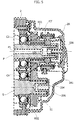
Figure 5 is a schematic cross-sectional view of the portion of gear change illustrated inFigure 3 , in the five-gear variant; and -
Figure 6 is a diagram of a production line for manufacturing the gear change device according to the invention. -
Figures 1 and2 , which regard the prior art, have already been discussed at the start of the present description. -
Figures 3 and4 of the annexed drawings show schematic sections in the assembled condition and in an exploded condition, respectively, of the end portion of the gear change device ofFigure 1 , modified according to the teachings of the present invention, to provide a gear change device with six gears. - The main characteristic of the gear change device according to the invention lies in the fact that, instead of using primary and secondary shafts of different lengths to obtain gear change devices with different numbers of gears, a modular structure is adopted for each of the aforesaid shafts, which envisages that to the end portion of the primary and secondary shafts, on the side opposite to the engine, a shaft-extension element is coupled in the case where it is desired to obtain the version of gear change with a higher number of gears.
- In
Figures 3-5 , the parts common to those illustrated inFigures 1 and2 are designated by the same reference numbers. - With reference, in particular, to
Figures 3 and4 , the main difference as compared to the known solution ofFigure 1 lies in the fact that both the primary shaft P and the secondary shaft S have a composite modular structure, including two shaft-extension elements E1 and E2 that are coupled to the end portions P1, S1 of the primary and secondary shafts P, S. - In the example illustrated, the shaft-extension element E1 has a tubular body, with an end of
larger diameter 101, extending from which is an intermediatecylindrical body 102, from which there in turn extends acylindrical shank 103 of smaller diameter. Thecylindrical shank 103 has its outer surface threaded for engagement by screwing within a threadedaxial hole 104 formed in the primary shaft P starting from itsend surface 105. - Likewise, the shaft-extension element E2 has an end of
larger diameter 201, an intermediatecylindrical portion 202, and anend shank 203 of smaller diameter, having its outer surface threaded, for engagement by screwing within a threadedaxial hole 204 made starting from theend surface 205 of the secondary shaft S. - The ends 101, 201 of the shaft-extension elements E1, E2 are rotatably supported within the
portion 2A of the gear change casing by means of the rolling bearings C5, C6. - As may be seen in
Figures 3 and4 , in the condition where the shaft-extension elements E1, E2 are coupled to the end portions P1, S1 of the primary and secondary shafts P, S, theintermediate portions - Mounted on the continuous cylindrical surface defined by the end portion P1 together with the
portion 102 of the shaft-extension element E1 is a bushing B1 that supports the gear R61 in rotation by means of a rolling bearing. Mounting is obtained by interference fit. The coupling surfaces between the bushing B1, the end portion P1, and theportion 101 of the shaft-extension element E1 are machined with a precision sufficient to ensure coaxiality of the end portion P1 of the primary shaft P and of the shaft-extension element E1, within a strict tolerance. - Also the
intermediate portion 202 of the shaft-extension element E2 and the end portion S1 of the secondary shaft S are adjacent to one another in the coupled condition and, since they have the same diameter, they define a continuous cylindrical surface. However, in this case, the coaxiality between the secondary shaft S and the shaft-extension element E2 is ensured by the interference fit of a cylindrical bushing B2 on adjacent hubs H1, H2 of the two gears R52, R62. The gear R52 is rigidly connected to the end portion S1 of the secondary shaft S, according to the prior art. Moreover, the gear R62 is rigidly connected, by interference fit, on theintermediate portion 202 of the shaft-extension element E2. Also in this case, the bushing B2 is interference-fitted on the hubs H1, H2, and the coupling surfaces are machined with a precision sufficient to ensure that the coaxiality between the end portion S1 of the secondary shaft S and the shaft-extension element E2 is guaranteed within a strict tolerance. - Thanks to the bushings B1, B2, there is ensured proper meshing of the gear pair R61, R62.
- According to the present invention, in the case where the gear change device has to be produced in a five-gear version, the shaft-extension elements E1, E2 are eliminated, as shown in
Figure 5 , so as not to require provision of two different primary and secondary shafts P, S. In this case, the two rolling bearings C5, C6 are eliminated. Theaxial holes caps - As is evident from the foregoing description, the gear change device according to the invention has a structure devised according to criteria of modularity, which enables production of gear changes with different numbers of gears on a single production line, with advantages of simplification of production and higher efficiency.
- Of course, even though the example illustrated herein refers to the case of a gear change that is to be produced in a five-gear version or in a six-gear version, the invention applies to gear change devices with any number of gears, and nothing rules out the possibility of the shaft-extension elements envisaged according to the invention being provided with more than one additional gear pair.
- Thanks to the present invention, it is possible to set up a single production line for gear change devices with different numbers of gears, according to what is illustrated schematically in
Figure 6 . In this figure, the reference T designates a single production line, which includes a succession of assembly stations S10, S20, S30, etc., where successive operations of assembly that are common to the two different versions of gear change device (for example, a six-gear version and a five-gear version) are carried out. In the example illustrated, in the final part the line splits up into two branches and hence proceeds towards a station S6, for assembly for example of the six-gear version, or else towards a station S5, for assembly of the five-gear version. In the station S6, the shaft-extension elements E1, E2 are coupled to the primary and secondary shafts P, S, whereas in the station S5 this operation is not carried out. Along each of the two branches of the line the final operations are carried out necessary to obtain, for example, the six-gear device ofFigure 3 or the five-gear device ofFigure 5 , respectively. However, it would be possible to envisage that the line remains single and includes different workstations for carrying out assembly of different versions of the gear change. - The structure of the gear change device as described above facilitates and simplifies the operations of assembly and at the same time ensures the precision of assembly that is necessary in order to obtain proper and reliable operation of the gear change device.
Claims (3)
- A gear change device for a motor vehicle, including:- a gear change casing (2),- at least one primary shaft, which is to be connected to the engine shaft of the motor vehicle,- at least one secondary shaft (S), having an axis (4) parallel to and spaced apart from the axis (3) of said primary shaft (P),- said primary and secondary shafts (P, S) being rotatably supported within said gear change casing (2) each by means of at least two rolling bearings (C1, C2; C3, C4) axially spaced apart from each other,- a plurality of gear pairs (R11, R12; R21, R22; R31, R32; R41, R42; R51, R52; R61, R62) corresponding to a plurality of forward-gear ratios, in which for each gear pair one gear is rigidly connected in rotation to one between said primary shaft (P) and said secondary shaft (S) and the other is free to rotate with respect to the other between said primary shaft (P) and said secondary shaft (S); and- a plurality of gear-engagement devices (F1, F2, F3) for coupling each of said freely rotating gears in rotation to the shaft on which it is mounted,- wherein said primary and secondary shafts (P, S) have end portions (P1, S1), on a side which is to be opposite with respect to the engine, which extend beyond respective rolling bearings (C2, C4) and carry at least one pair of said gears (R51, R52),said gear change device being characterized in that said end portions (P1, S1) of said primary shaft (P) and of said secondary shaft (S) are coupled to respective shaft-extension elements (E1, E2), which carry a further pair of said gears (R61, R62),
wherein:- a first one of said end portions (P1) of the primary and secondary shafts (P, S) carries a first gear (R51) mounted free to rotate thereon,- the second one of said end portions (S1) of the primary and secondary shafts (P, S) carries a second gear (R52) rigidly connected thereto and meshing with the first gear (R51) carried by said first end portion (P1),- a first one of said shaft-extension elements (E1), which can be coupled to said first end portion (P1) carries a third gear (R61) mounted free to rotate thereon,- a second one of said shaft-extension elements (E2), which can be coupled to said second end portion (S1), carries a fourth gear (R62) rigidly connected thereto and meshing with said third gear (R61) carried by the first shaft-extension element (E1), and- said first end portion (P1) also carries a gear-engagement device (F2, F2') for coupling selectively in rotation one between said first gear (R51) and said third gear (R61) with said first end portion (P1),said gear change device being characterized in that:- in their coupled condition, said first end portion (P1) and said first shaft-extension element (E1) define together a continuous cylindrical surface, on which a cylindrical bushing (B1) is mounted by an interference-fit, so as to ensure coaxiality of the first shaft-extension element (E1) with the primary shaft (P), said bushing (B1) rotatably supporting said third gear (R61) via a rolling bearing, and- in the coupled condition of said second end portion (S1) and of said second shaft-extension element (E2), said second gear (R52) and said fourth gear (R62) have adjacent hubs (H1, H2) that define together a continuous cylindrical surface, on which a cylindrical bushing (B2) is mounted by an interference-fit, so as to ensure coaxiality of the second shaft-extension element (E2) with the secondary shaft (S). - The gear change device according to Claim 1, characterized in that said shaft-extension elements (E1, E2) each have an end (101, 201) supported in rotation by the gear change casing (2, 2A) by means of a rolling bearing (C5, C6).
- The gear change device according to Claims 2, characterized in that each of said shaft-extension elements (E1, E2) has an intermediate cylindrical portion (102, 202), from which there extends a threaded shank (103, 203) of smaller diameter, which is screwed into a threaded axial hole (104, 204) formed in each of said primary and secondary shafts (P, S) starting from its end surface.
Priority Applications (3)
| Application Number | Priority Date | Filing Date | Title |
|---|---|---|---|
| EP16166438.8A EP3236109B1 (en) | 2016-04-21 | 2016-04-21 | Gear change device for a motor vehicle and method for manufacture thereof |
| BR112018069159A BR112018069159A2 (en) | 2016-04-21 | 2017-03-08 | gear shifting device for a motor vehicle and method of manufacturing it |
| PCT/IB2017/051358 WO2017182892A1 (en) | 2016-04-21 | 2017-03-08 | Gear change device for a motor vehicle and method for manufacture thereof |
Applications Claiming Priority (1)
| Application Number | Priority Date | Filing Date | Title |
|---|---|---|---|
| EP16166438.8A EP3236109B1 (en) | 2016-04-21 | 2016-04-21 | Gear change device for a motor vehicle and method for manufacture thereof |
Publications (2)
| Publication Number | Publication Date |
|---|---|
| EP3236109A1 EP3236109A1 (en) | 2017-10-25 |
| EP3236109B1 true EP3236109B1 (en) | 2019-06-05 |
Family
ID=56119277
Family Applications (1)
| Application Number | Title | Priority Date | Filing Date |
|---|---|---|---|
| EP16166438.8A Active EP3236109B1 (en) | 2016-04-21 | 2016-04-21 | Gear change device for a motor vehicle and method for manufacture thereof |
Country Status (3)
| Country | Link |
|---|---|
| EP (1) | EP3236109B1 (en) |
| BR (1) | BR112018069159A2 (en) |
| WO (1) | WO2017182892A1 (en) |
Families Citing this family (1)
| Publication number | Priority date | Publication date | Assignee | Title |
|---|---|---|---|---|
| US20250180105A1 (en) * | 2023-12-04 | 2025-06-05 | Schaeffler Technologies AG & Co. KG | Transmission assembly for a vehicle |
Family Cites Families (2)
| Publication number | Priority date | Publication date | Assignee | Title |
|---|---|---|---|---|
| AT398334B (en) * | 1990-01-23 | 1994-11-25 | Steyr Daimler Puch Ag | SPROCKET GEARBOX |
| FR2726623B1 (en) * | 1994-11-04 | 1997-01-31 | Peugeot | GEARBOX |
-
2016
- 2016-04-21 EP EP16166438.8A patent/EP3236109B1/en active Active
-
2017
- 2017-03-08 BR BR112018069159A patent/BR112018069159A2/en not_active Application Discontinuation
- 2017-03-08 WO PCT/IB2017/051358 patent/WO2017182892A1/en not_active Ceased
Non-Patent Citations (1)
| Title |
|---|
| None * |
Also Published As
| Publication number | Publication date |
|---|---|
| BR112018069159A2 (en) | 2019-01-22 |
| EP3236109A1 (en) | 2017-10-25 |
| WO2017182892A1 (en) | 2017-10-26 |
Similar Documents
| Publication | Publication Date | Title |
|---|---|---|
| US10794460B2 (en) | Differential device | |
| US10612585B2 (en) | Angular contact bearing and gear mechanism comprising a thrust washer | |
| US8707813B2 (en) | Shiftable twin gear for a twin-clutch transmission and twin-clutch transmission | |
| JPS58113659A (en) | Fixing structure for change gear and shaft in speed change gear for automobile | |
| RU2549586C2 (en) | Planetary mechanism with several driving gears | |
| CA3011135A1 (en) | Transmission device for splitting torque between two coaxial gears, in particular for a planetary gearing for aeronautic applications, and method for manufacturing and assembling said transmission device | |
| JP2012505352A5 (en) | ||
| EP3187742B1 (en) | Assembling process for mounting a rolling bearing on a gear shaft, and gear assembly obtainable by such a process | |
| KR102230927B1 (en) | Device for switching a first and second switching element, and transmission comprising such a device | |
| US20170284509A1 (en) | Shift Gear Wheel for High Gear Ratio Spread | |
| US9821654B2 (en) | Transverse dual planetary system | |
| US3370477A (en) | Shifting mechanism | |
| US20170307078A1 (en) | Stepped planetary gear | |
| US11221069B2 (en) | Shifting mechanism for a transmission | |
| US7220208B2 (en) | Device for lubrication of a gear | |
| EP3236109A1 (en) | Gear change device for a motor vehicle and method for manufacture thereof | |
| KR20020052176A (en) | Gearboxes | |
| JP7479355B2 (en) | Mechanical reducer and geared motor using the same | |
| EP1866557B1 (en) | Seven-gear gearbox for a motorcar double clutch transmission | |
| EP2746085B1 (en) | Gear change device for a motor-vehicle | |
| US7396313B2 (en) | Planetary gear train transmission | |
| CN103998804B (en) | Gear shifting device with rotational lost motion of the shifting shaft and motor vehicle transmission with such a shifting device | |
| US10295038B2 (en) | Push-type transmission mechanism | |
| US9593763B2 (en) | Gearing assembly having a planetary stage | |
| KR20170035143A (en) | Planetary gear assembly and the method thereof |
Legal Events
| Date | Code | Title | Description |
|---|---|---|---|
| PUAI | Public reference made under article 153(3) epc to a published international application that has entered the european phase |
Free format text: ORIGINAL CODE: 0009012 |
|
| STAA | Information on the status of an ep patent application or granted ep patent |
Free format text: STATUS: REQUEST FOR EXAMINATION WAS MADE |
|
| 17P | Request for examination filed |
Effective date: 20170516 |
|
| AK | Designated contracting states |
Kind code of ref document: A1 Designated state(s): AL AT BE BG CH CY CZ DE DK EE ES FI FR GB GR HR HU IE IS IT LI LT LU LV MC MK MT NL NO PL PT RO RS SE SI SK SM TR |
|
| AX | Request for extension of the european patent |
Extension state: BA ME |
|
| GRAP | Despatch of communication of intention to grant a patent |
Free format text: ORIGINAL CODE: EPIDOSNIGR1 |
|
| STAA | Information on the status of an ep patent application or granted ep patent |
Free format text: STATUS: GRANT OF PATENT IS INTENDED |
|
| INTG | Intention to grant announced |
Effective date: 20181221 |
|
| GRAS | Grant fee paid |
Free format text: ORIGINAL CODE: EPIDOSNIGR3 |
|
| GRAA | (expected) grant |
Free format text: ORIGINAL CODE: 0009210 |
|
| STAA | Information on the status of an ep patent application or granted ep patent |
Free format text: STATUS: THE PATENT HAS BEEN GRANTED |
|
| AK | Designated contracting states |
Kind code of ref document: B1 Designated state(s): AL AT BE BG CH CY CZ DE DK EE ES FI FR GB GR HR HU IE IS IT LI LT LU LV MC MK MT NL NO PL PT RO RS SE SI SK SM TR |
|
| REG | Reference to a national code |
Ref country code: GB Ref legal event code: FG4D |
|
| REG | Reference to a national code |
Ref country code: CH Ref legal event code: EP |
|
| REG | Reference to a national code |
Ref country code: AT Ref legal event code: REF Ref document number: 1140326 Country of ref document: AT Kind code of ref document: T Effective date: 20190615 |
|
| REG | Reference to a national code |
Ref country code: IE Ref legal event code: FG4D |
|
| REG | Reference to a national code |
Ref country code: DE Ref legal event code: R096 Ref document number: 602016014706 Country of ref document: DE |
|
| REG | Reference to a national code |
Ref country code: NL Ref legal event code: MP Effective date: 20190605 |
|
| REG | Reference to a national code |
Ref country code: LT Ref legal event code: MG4D |
|
| PG25 | Lapsed in a contracting state [announced via postgrant information from national office to epo] |
Ref country code: ES Free format text: LAPSE BECAUSE OF FAILURE TO SUBMIT A TRANSLATION OF THE DESCRIPTION OR TO PAY THE FEE WITHIN THE PRESCRIBED TIME-LIMIT Effective date: 20190605 Ref country code: LT Free format text: LAPSE BECAUSE OF FAILURE TO SUBMIT A TRANSLATION OF THE DESCRIPTION OR TO PAY THE FEE WITHIN THE PRESCRIBED TIME-LIMIT Effective date: 20190605 Ref country code: HR Free format text: LAPSE BECAUSE OF FAILURE TO SUBMIT A TRANSLATION OF THE DESCRIPTION OR TO PAY THE FEE WITHIN THE PRESCRIBED TIME-LIMIT Effective date: 20190605 Ref country code: FI Free format text: LAPSE BECAUSE OF FAILURE TO SUBMIT A TRANSLATION OF THE DESCRIPTION OR TO PAY THE FEE WITHIN THE PRESCRIBED TIME-LIMIT Effective date: 20190605 Ref country code: NO Free format text: LAPSE BECAUSE OF FAILURE TO SUBMIT A TRANSLATION OF THE DESCRIPTION OR TO PAY THE FEE WITHIN THE PRESCRIBED TIME-LIMIT Effective date: 20190905 Ref country code: AL Free format text: LAPSE BECAUSE OF FAILURE TO SUBMIT A TRANSLATION OF THE DESCRIPTION OR TO PAY THE FEE WITHIN THE PRESCRIBED TIME-LIMIT Effective date: 20190605 Ref country code: SE Free format text: LAPSE BECAUSE OF FAILURE TO SUBMIT A TRANSLATION OF THE DESCRIPTION OR TO PAY THE FEE WITHIN THE PRESCRIBED TIME-LIMIT Effective date: 20190605 |
|
| PG25 | Lapsed in a contracting state [announced via postgrant information from national office to epo] |
Ref country code: LV Free format text: LAPSE BECAUSE OF FAILURE TO SUBMIT A TRANSLATION OF THE DESCRIPTION OR TO PAY THE FEE WITHIN THE PRESCRIBED TIME-LIMIT Effective date: 20190605 Ref country code: RS Free format text: LAPSE BECAUSE OF FAILURE TO SUBMIT A TRANSLATION OF THE DESCRIPTION OR TO PAY THE FEE WITHIN THE PRESCRIBED TIME-LIMIT Effective date: 20190605 Ref country code: GR Free format text: LAPSE BECAUSE OF FAILURE TO SUBMIT A TRANSLATION OF THE DESCRIPTION OR TO PAY THE FEE WITHIN THE PRESCRIBED TIME-LIMIT Effective date: 20190906 Ref country code: BG Free format text: LAPSE BECAUSE OF FAILURE TO SUBMIT A TRANSLATION OF THE DESCRIPTION OR TO PAY THE FEE WITHIN THE PRESCRIBED TIME-LIMIT Effective date: 20190905 |
|
| REG | Reference to a national code |
Ref country code: AT Ref legal event code: MK05 Ref document number: 1140326 Country of ref document: AT Kind code of ref document: T Effective date: 20190605 |
|
| PG25 | Lapsed in a contracting state [announced via postgrant information from national office to epo] |
Ref country code: PT Free format text: LAPSE BECAUSE OF FAILURE TO SUBMIT A TRANSLATION OF THE DESCRIPTION OR TO PAY THE FEE WITHIN THE PRESCRIBED TIME-LIMIT Effective date: 20191007 Ref country code: RO Free format text: LAPSE BECAUSE OF FAILURE TO SUBMIT A TRANSLATION OF THE DESCRIPTION OR TO PAY THE FEE WITHIN THE PRESCRIBED TIME-LIMIT Effective date: 20190605 Ref country code: NL Free format text: LAPSE BECAUSE OF FAILURE TO SUBMIT A TRANSLATION OF THE DESCRIPTION OR TO PAY THE FEE WITHIN THE PRESCRIBED TIME-LIMIT Effective date: 20190605 Ref country code: CZ Free format text: LAPSE BECAUSE OF FAILURE TO SUBMIT A TRANSLATION OF THE DESCRIPTION OR TO PAY THE FEE WITHIN THE PRESCRIBED TIME-LIMIT Effective date: 20190605 Ref country code: EE Free format text: LAPSE BECAUSE OF FAILURE TO SUBMIT A TRANSLATION OF THE DESCRIPTION OR TO PAY THE FEE WITHIN THE PRESCRIBED TIME-LIMIT Effective date: 20190605 Ref country code: SK Free format text: LAPSE BECAUSE OF FAILURE TO SUBMIT A TRANSLATION OF THE DESCRIPTION OR TO PAY THE FEE WITHIN THE PRESCRIBED TIME-LIMIT Effective date: 20190605 Ref country code: AT Free format text: LAPSE BECAUSE OF FAILURE TO SUBMIT A TRANSLATION OF THE DESCRIPTION OR TO PAY THE FEE WITHIN THE PRESCRIBED TIME-LIMIT Effective date: 20190605 |
|
| PG25 | Lapsed in a contracting state [announced via postgrant information from national office to epo] |
Ref country code: SM Free format text: LAPSE BECAUSE OF FAILURE TO SUBMIT A TRANSLATION OF THE DESCRIPTION OR TO PAY THE FEE WITHIN THE PRESCRIBED TIME-LIMIT Effective date: 20190605 Ref country code: IS Free format text: LAPSE BECAUSE OF FAILURE TO SUBMIT A TRANSLATION OF THE DESCRIPTION OR TO PAY THE FEE WITHIN THE PRESCRIBED TIME-LIMIT Effective date: 20191005 |
|
| REG | Reference to a national code |
Ref country code: DE Ref legal event code: R097 Ref document number: 602016014706 Country of ref document: DE |
|
| PG25 | Lapsed in a contracting state [announced via postgrant information from national office to epo] |
Ref country code: TR Free format text: LAPSE BECAUSE OF FAILURE TO SUBMIT A TRANSLATION OF THE DESCRIPTION OR TO PAY THE FEE WITHIN THE PRESCRIBED TIME-LIMIT Effective date: 20190605 |
|
| PLBE | No opposition filed within time limit |
Free format text: ORIGINAL CODE: 0009261 |
|
| STAA | Information on the status of an ep patent application or granted ep patent |
Free format text: STATUS: NO OPPOSITION FILED WITHIN TIME LIMIT |
|
| PG25 | Lapsed in a contracting state [announced via postgrant information from national office to epo] |
Ref country code: DK Free format text: LAPSE BECAUSE OF FAILURE TO SUBMIT A TRANSLATION OF THE DESCRIPTION OR TO PAY THE FEE WITHIN THE PRESCRIBED TIME-LIMIT Effective date: 20190605 Ref country code: PL Free format text: LAPSE BECAUSE OF FAILURE TO SUBMIT A TRANSLATION OF THE DESCRIPTION OR TO PAY THE FEE WITHIN THE PRESCRIBED TIME-LIMIT Effective date: 20190605 |
|
| 26N | No opposition filed |
Effective date: 20200306 |
|
| PG25 | Lapsed in a contracting state [announced via postgrant information from national office to epo] |
Ref country code: SI Free format text: LAPSE BECAUSE OF FAILURE TO SUBMIT A TRANSLATION OF THE DESCRIPTION OR TO PAY THE FEE WITHIN THE PRESCRIBED TIME-LIMIT Effective date: 20190605 |
|
| PG25 | Lapsed in a contracting state [announced via postgrant information from national office to epo] |
Ref country code: MC Free format text: LAPSE BECAUSE OF FAILURE TO SUBMIT A TRANSLATION OF THE DESCRIPTION OR TO PAY THE FEE WITHIN THE PRESCRIBED TIME-LIMIT Effective date: 20190605 |
|
| REG | Reference to a national code |
Ref country code: CH Ref legal event code: PL |
|
| PG25 | Lapsed in a contracting state [announced via postgrant information from national office to epo] |
Ref country code: LU Free format text: LAPSE BECAUSE OF NON-PAYMENT OF DUE FEES Effective date: 20200421 Ref country code: LI Free format text: LAPSE BECAUSE OF NON-PAYMENT OF DUE FEES Effective date: 20200430 Ref country code: CH Free format text: LAPSE BECAUSE OF NON-PAYMENT OF DUE FEES Effective date: 20200430 |
|
| REG | Reference to a national code |
Ref country code: BE Ref legal event code: MM Effective date: 20200430 |
|
| PG25 | Lapsed in a contracting state [announced via postgrant information from national office to epo] |
Ref country code: BE Free format text: LAPSE BECAUSE OF NON-PAYMENT OF DUE FEES Effective date: 20200430 |
|
| GBPC | Gb: european patent ceased through non-payment of renewal fee |
Effective date: 20200421 |
|
| PG25 | Lapsed in a contracting state [announced via postgrant information from national office to epo] |
Ref country code: GB Free format text: LAPSE BECAUSE OF NON-PAYMENT OF DUE FEES Effective date: 20200421 Ref country code: IE Free format text: LAPSE BECAUSE OF NON-PAYMENT OF DUE FEES Effective date: 20200421 |
|
| PGFP | Annual fee paid to national office [announced via postgrant information from national office to epo] |
Ref country code: FR Payment date: 20210427 Year of fee payment: 6 Ref country code: DE Payment date: 20210428 Year of fee payment: 6 Ref country code: IT Payment date: 20210412 Year of fee payment: 6 |
|
| PG25 | Lapsed in a contracting state [announced via postgrant information from national office to epo] |
Ref country code: MT Free format text: LAPSE BECAUSE OF FAILURE TO SUBMIT A TRANSLATION OF THE DESCRIPTION OR TO PAY THE FEE WITHIN THE PRESCRIBED TIME-LIMIT Effective date: 20190605 Ref country code: CY Free format text: LAPSE BECAUSE OF FAILURE TO SUBMIT A TRANSLATION OF THE DESCRIPTION OR TO PAY THE FEE WITHIN THE PRESCRIBED TIME-LIMIT Effective date: 20190605 |
|
| PG25 | Lapsed in a contracting state [announced via postgrant information from national office to epo] |
Ref country code: MK Free format text: LAPSE BECAUSE OF FAILURE TO SUBMIT A TRANSLATION OF THE DESCRIPTION OR TO PAY THE FEE WITHIN THE PRESCRIBED TIME-LIMIT Effective date: 20190605 |
|
| REG | Reference to a national code |
Ref country code: DE Ref legal event code: R119 Ref document number: 602016014706 Country of ref document: DE |
|
| PG25 | Lapsed in a contracting state [announced via postgrant information from national office to epo] |
Ref country code: FR Free format text: LAPSE BECAUSE OF NON-PAYMENT OF DUE FEES Effective date: 20220430 Ref country code: DE Free format text: LAPSE BECAUSE OF NON-PAYMENT OF DUE FEES Effective date: 20221103 |
|
| PG25 | Lapsed in a contracting state [announced via postgrant information from national office to epo] |
Ref country code: IT Free format text: LAPSE BECAUSE OF NON-PAYMENT OF DUE FEES Effective date: 20220421 |