EP3236055A1 - An engine diagnostics configuration method - Google Patents
An engine diagnostics configuration method Download PDFInfo
- Publication number
- EP3236055A1 EP3236055A1 EP16166213.5A EP16166213A EP3236055A1 EP 3236055 A1 EP3236055 A1 EP 3236055A1 EP 16166213 A EP16166213 A EP 16166213A EP 3236055 A1 EP3236055 A1 EP 3236055A1
- Authority
- EP
- European Patent Office
- Prior art keywords
- equivalent
- diagnostic
- engine
- function
- monitor
- Prior art date
- Legal status (The legal status is an assumption and is not a legal conclusion. Google has not performed a legal analysis and makes no representation as to the accuracy of the status listed.)
- Granted
Links
Images


Classifications
-
- F—MECHANICAL ENGINEERING; LIGHTING; HEATING; WEAPONS; BLASTING
- F02—COMBUSTION ENGINES; HOT-GAS OR COMBUSTION-PRODUCT ENGINE PLANTS
- F02D—CONTROLLING COMBUSTION ENGINES
- F02D41/00—Electrical control of supply of combustible mixture or its constituents
- F02D41/22—Safety or indicating devices for abnormal conditions
-
- Y—GENERAL TAGGING OF NEW TECHNOLOGICAL DEVELOPMENTS; GENERAL TAGGING OF CROSS-SECTIONAL TECHNOLOGIES SPANNING OVER SEVERAL SECTIONS OF THE IPC; TECHNICAL SUBJECTS COVERED BY FORMER USPC CROSS-REFERENCE ART COLLECTIONS [XRACs] AND DIGESTS
- Y02—TECHNOLOGIES OR APPLICATIONS FOR MITIGATION OR ADAPTATION AGAINST CLIMATE CHANGE
- Y02T—CLIMATE CHANGE MITIGATION TECHNOLOGIES RELATED TO TRANSPORTATION
- Y02T10/00—Road transport of goods or passengers
- Y02T10/10—Internal combustion engine [ICE] based vehicles
- Y02T10/40—Engine management systems
Definitions
- the present disclosure relates to a method of configuration using equivalent values and is particularly, although not exclusively, concerned with a method of configuring an engine diagnostic system using equivalent function identifiers.
- Modern vehicles often comprise a plurality of sensors configured to monitor the operating conditions of the vehicle.
- the outputs of the sensors may be used by many different systems of the vehicle, in order for the systems to operate efficiently.
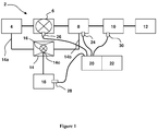
- a previously proposed vehicle 2 may comprise an air inlet 4, an inlet manifold 8, an engine 10 and an exhaust 12.
- An inlet throttle 6 may be provided between the air inlet 4 and the inlet manifold 8 to control the flow of air to the engine 10.
- the vehicle 2 may also comprise a super aspirator 14.
- An inlet 14a of the super aspirator may be in fluid communication with the air inlet 4 and an outlet 14b of the super aspirator may be in fluid communication with the inlet manifold 8.
- This pressure difference may drive a flow of air through the super aspirator 14.
- the flow of air through the super aspirator 14 may be controlled by a super aspirator shut off valve 16 provided on the super aspirator between the inlet 14a and the outlet 14b.
- a super aspirator shut off valve 16 provided on the super aspirator between the inlet 14a and the outlet 14b.
- the pressure of air at a throat 14c of the super aspirator may be lower than the pressure at the air inlet 4 and in the inlet manifold 8, e.g. the super aspirator 14 may generate a vacuum pressure at the throat 14c.
- the super aspirator 14 may be used as a vacuum source for systems on the vehicle such as a brake booster system 18.
- the vehicle may further comprise a controller 20 configured to monitor and control the operation of the vehicle 2.
- the controller 20 may receive inputs from sensors provided on the vehicle, such sensors may include, but are not limited to, a Manifold Air Pressure (MAP) sensor 24, configured to measure a pressure of air within the inlet manifold 8; a Throttle Position Sensor (TPS) 26, configured to measure a position of the inlet throttle, a brake boost sensor 28, configured to measure a brake boost pressure of the brake boost system 18; and a crank position sensor 30, configured to detect an angle of rotation of a crank shaft (not shown) of the engine 10.
- MAP Manifold Air Pressure
- TPS Throttle Position Sensor
- the controller 20 may consider the inputs provided from the sensors and may control the operation of the vehicle. For example, a pressure reading from the MAP sensor 24 and a position reading from the crank position sensor 30 may be considered to determine a timing and quantity of fuel to be injected into a cylinder (not shown) of the engine 10. Additionally or alternatively, a position of the super aspirator shut of valve 16 may be controlled to maintain the brake booster pressure at or below a threshold value, according to readings from the brake boost sensor 28.
- the readings from one or more of the sensors received by the controller 20 may be outside the normal operating ranges for the vehicle 2. It may not be possible to determine whether the fault has occurred with the vehicle component or with the sensor itself. Nevertheless, it may be desirable to perform certain reactions to ensure the controller 20 is able to continue effectively controlling the operation of the vehicle 2.
- An engine diagnostics system 22 may be provided, which may be configured to perform such reactions in the event of a fault being detected.
- the diagnostic system 22 may detect and react to faults in the wider powertrain, e.g. in the transmission, after-treatment systems, etc., and in the vehicle in which the engine is provided, for example in the safety systems of the vehicle.
- the engine diagnostics system 22 may be capable of monitoring a plurality of fault statuses using a plurality of fault monitors.
- the fault monitors may correspond to a particular component or sensor of the vehicle and may trigger, e.g. determine that a fault has occurred, when no signal is received from the sensor.
- the fault monitors may be configured to determine whether a particular value or range of values is being detected by the sensor.
- a first fault monitor may detect a MAP fault, triggered when the MAP sensor 24 records a pressure below a threshold value; a second fault monitor may detect a break booster fault, triggered when the break booster pressure sensor 28 records a pressure above a threshold value; and a third fault monitor may detect a crank sensor fault, triggered when an invalid position is received from the crank position sensor 30.
- the engine diagnostics system 22 may perform one or more functions as a reaction to the detection of the fault. Each of the functions may be performed when a certain fault condition is met. Such fault conditions may, for example, define that a function is performed as soon as a fault is detected. Alternatively, the fault condition may specify that the function is performed when the fault persists for a certain period of time. Fault conditions or LIMits may be referenced within the engine diagnostic system 22 as LIMs.
- a function which can be performed by the engine diagnostics system 22 as a reaction to a fault being detected, may be referenced within the engine diagnostics system 22 by a Function Identifier (FId).
- the FIds may relate to reactions which inhibit or enable other vehicle functions, or reconfigure how the controller 20 operates the vehicle.
- the FIds may also relate to reactions, which affect how the engine diagnostics system 22 responds to future diagnostic events.
- the reactions taken may comprise: reconfiguring the vehicle injection system such that fuel injection quantities are calculated based on a reading from the TPS 26 rather than the MAP sensor 24; closing the super aspirator shut-off valve 16 to protect the pressure difference across the inlet throttle; and deactivating any fault monitors relating to the brake booster pressure, which may trigger as a result of closing the super aspirator shut-off valve 16.
- the engine diagnostic system may be configured with an engine diagnostic configuration setting 200.
- the configuration setting 200 may comprise a plurality of FId arrays 204 and a plurality of corresponding LIM arrays 206.
- the FId arrays 204 may comprise a plurality of FIds defining the reactions to be taken following detection of a particular fault.
- the LIM arrays 206 may comprise a plurality of LIMs defining the fault conditions under which each of the reactions, referenced by the FIds in the corresponding FId array, should be taken.
- Each element in the LIM array 206 may relate to the corresponding element in the corresponding FId array 204, such that the first LIM may define the fault conditions for performing the reaction defined by the first FId in the corresponding FId array, the second LIM may define the fault conditions for the second FId, etc.
- each of the pairs of corresponding FId and LIM arrays 204, 206 may be associated with a Diagnostic Fault Check (DFC), which corresponds to a fault monitor of the engine diagnostic system 22.
- DFC Diagnostic Fault Check
- each fault monitor of the engine diagnostic system 22 may be operable to determine a particular fault condition of the vehicle 2.
- Each pair of arrays 204, 206 may be associated with a different DFC 202.
- Each DFC 202 may support a predetermined number of FIds and corresponding LIMs. The number of FIds and LIMs that are supported by each DFC may vary between the different DFCs 202. Hence, each FId and LIM array 204, 206 in the configuration setting 200 may be sized to provide the appropriate number of FIds and LIMs.
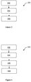
- the engine diagnostic system 22 may react according to a previously proposed method 300.
- the method may start at a first step 302, when a fault is detected by a fault monitor.
- the engine diagnostic system 22 may refer to the engine diagnostic configuration setting 200, which has been applied to the engine diagnostic system 22, to determine the FId array 204 and LIM array 206 associated with the relevant fault monitor, e.g. according to the corresponding DFC.
- the engine diagnostic system 22 may consider each of the FIds and corresponding LIMs stored in the FId and LIM arrays 204, 206 in turn. For each FId, the engine diagnostic system 22 may determine whether the fault condition defined by the corresponding LIM has been met. If the fault condition has been met, the engine diagnostic system 22 may perform the reaction referenced by the FId. The engine diagnostic system 22 may continue considering each of the FId and LIM values until reaching the end of the arrays 204, 206.
- Such systems may comprise different fault monitors, associated with different DFCs, which may support different numbers of FIds and LIMs, and/or may support different FIds.
- DFCs Different numbers of FIds and LIMs
- FIds FIds
- LIMs LIMs
- FIds FIds
- FIds FIds
- FIds FIds
- LIMs LIMs
- a computer implemented method for configuring an engine diagnostic system comprising: determining a set of diagnostic monitors available within the engine diagnostic system; determining for each diagnostic monitor, one or more desired functions to be performed following a detection event from the diagnostic monitor and a function identifier associated with the or each desired function; if the function identifier is not supported by the engine diagnostic system, determining an equivalent function identifier, the equivalent function identifier being equivalent to the desired function identifier and supported by the engine diagnostic system; and configuring the engine diagnostic system using the equivalent function identifier.
- the diagnostic system may detect and react to faults in the wider powertrain, e.g. in the transmission, after-treatment systems, etc., and in the vehicle in which the engine is provided, for example in the safety systems of the vehicle.
- the method may further comprise providing a master array associated with a first diagnostic monitor.
- the master array may comprise one or more function identifiers corresponding to functions to be performed following the detection event from the first diagnostic monitor.
- the method may further comprise searching for the first diagnostic monitor among the set of diagnostic monitors available within the engine diagnostic system. If the first diagnostic monitor is found amount the set of diagnostic monitors, the method may further comprise translating the master array into an application specific array associated with the first diagnostic monitor.
- the method may further comprise identifying an equivalent array associated with an equivalent diagnostic monitor, wherein the equivalent diagnostic monitor is equivalent to the first diagnostic monitor.
- the equivalent diagnostic monitor may be identified from a stored list of equivalent diagnostic monitors.
- the method may further comprise translating the master array into an application specific array associated with the equivalent diagnostic monitor.
- the identified equivalent diagnostic monitor may be available within the engine diagnostic system.
- Translating the master array into an application specific array may comprise determining whether the or each function identifier within the master array is available within the engine diagnostic system. If the function identifier is available within the engine diagnostic system, the function identifier may be copied from the master array into the application specific array.
- an equivalent function identifier may be determined.
- the equivalent function identifiers may be determined by referring to a list of equivalent function identifiers associated with the function identifiers.
- the method may further comprise copying the equivalent function identifier into the application specific array.
- the function identifiers and equivalent function identifiers may be translated in a predetermined order of priority.
- the function identifiers may be translated in the order in which they are provided in the master array or equivalent array.
- the method may further comprise determining an equivalent diagnostic monitor, which is equivalent to the diagnostic monitor available within the diagnostic system.
- the function identifiers and/or the equivalent function identifiers may be determined by referring to the function identifiers associated with the equivalent diagnostic monitor.
- the equivalent diagnostic monitor may be determined by referring to a list of equivalent diagnostic monitors associated with the available diagnostic monitor.
- the equivalent diagnostic monitor may or may not be supported by the engine diagnostic system.
- the method may further comprise determining the number of function identifiers, which can be associated with the available diagnostic monitor of the engine diagnostic system.
- the number of function identifiers and equivalent function identifiers used to calibrate the engine diagnostics systems may be less than or equal to the number of function identifiers that can be associated with the available diagnostic monitor.
- the method may further comprise determining one or more redundant function identifiers, which may exist in, but are not supported by the engine diagnostic system. Equivalent function identifiers may not determined for function identifiers that are redundant function identifiers.
- the redundant function identifiers may be determined by referring to a list of redundant function identifiers associated with the engine diagnostic system.
- the function identifiers may be determined by referring to an existing calibration setting for another engine diagnostic system. For example, the function identifiers may be determined by referring to the function identifiers associated with the same or equivalent diagnostic monitors within the existing calibration setting.
- the method may further comprise reporting one or more diagnostic monitors and/or function identifiers referenced within the existing calibration setting that are not supported by the engine diagnostic system and have no equivalent diagnostic monitors and/or function identifiers respectively.
- a method of calibrating an engine diagnostic system comprising: determining one or more desired function identifiers the or each function identifier being associated with a desired function.
- the desired functions may be desirable to perform following a predetermined diagnostic event.
- the method may comprise determining one or more equivalent function identifiers for the or each desired function identifier; the equivalent function identifiers being equivalent to the or each desired function identifier.
- the method may further comprise generating a calibration setting for the desired engine diagnostic system comprising the equivalent function identifiers.
- the method may further comprise determining an available diagnostic monitor, which is available within the desired engine diagnostic system.
- the desired reaction identifiers may be associated with the available diagnostic monitor, e.g. within the calibration setting.
- One or more of the function identifiers may not be supported by the engine diagnostic system.
- the equivalent function identifiers may be determined for each of the function identifiers that are not supported by the engine diagnostic system.
- the method may further comprise determining a set of supported function identifiers, which are supported by the desired engine diagnostic system.
- the determined function identifiers and/or equivalent function identifiers may be supported function identifiers.
- a method of populating a data structure comprising a plurality of arrays, the method comprising: identifying a set of arrays within the data structure and a set of available array elements; determining a desired set of array elements for each of the arrays; determining one or more equivalent array elements associated with one or more of the desired array elements, wherein the equivalent array elements are within the set of available array elements; and populating the arrays with the desired and equivalent array elements.
- the populated array elements may be within the set of available array elements.
- the invention also provides software such as a computer program or a computer program product for carrying out any of the methods described herein, and a computer readable medium having stored thereon a program for carrying out any of the methods described herein.
- a computer program embodying the invention may be stored on a computer-readable medium, or it could, for example, be in the form of a signal such as a downloadable data signal provided from an Internet website, or it could be in any other form.
- the engine diagnostic configuration setting 200 may be applied to any compatible engine diagnostic system 22.
- each of the DFCs may be required to support the same numbers of FIds and LIMs as defined in the arrays 204, 206.
- a master engine diagnostics configuration setting may be generated.
- the master engine diagnostics configuration setting may be similar to the engine diagnostics configuration setting 200 described above, however the master engine diagnostics configuration setting may comprise information relating to all engine diagnostic systems of interest. Such information may include a database of all DFCs supported by all engine diagnostic systems of interest and associated arrays of FIds and LIM to be associated with the DFCs.
- the master engine diagnostics configuration setting may also comprise a list of all FIds defined within each engine diagnostic systems of interest.
- the master engine diagnostics configuration setting may be applied to a desired engine diagnostics system by associating the relevant FId and LIM arrays with the relevant DFCs of the desired engine diagnostics system.
- the master engine diagnostics configuration setting may comprise information associating DFCs with other DFCs that may be equivalent, e.g. which relate to same or an equivalent fault monitor concerned with, for example, the same sensor value or range of values, vehicle component or fault.
- Equivalent DFCs may be configured once within the master engine diagnostics configuration setting, e.g. a single one of the equivalent fault monitors may be configured, and the setting may be applied to all equivalent fault monitors. Determining equivalencies in this way may allow changes to configuration settings required in the future to be made to a single FId or LIM array 204, 206, rather than to each of the equivalents individually.
- FId and LIM arrays associated with equivalent DFCs may be applied, as described in more detail below.
- the master engine diagnostics configuration setting may comprise information associating FIds with other FIds that may be equivalent, e.g. relate to the same function, which can be performed as a reaction following a diagnostic event. This may allow a FId array within the master engine diagnostic configuration setting to be populated with FIds, which are not supported by all engine diagnostic systems, but which have equivalents across one or more of the diagnostic systems.
- any FId values that are not supported by the desired engine diagnostic system may be replaced by an equivalent FId, which is supported by the desired engine diagnostic system, as described in more detail below.
- the master engine diagnostics configuration setting may also include information relating to the number of FIds, which can be associated with each fault monitor within each engine diagnostics system of interest.
- the master engine diagnostics configuration setting When applying the master engine diagnostics configuration setting to a desired engine diagnostic system, only the supported number of FId and LIM may be applied. Hence a single array of FIds may be maintained for each DFC and its equivalents without concern that that number of FIds will be unsupported by one or more engine diagnostic systems of interest.
- the FIds may be added to each array in order of priority, to ensure that the most important FIds are applied to any engine diagnostic systems that do not support the full number of FIds populated in the array.
- the master engine diagnostics configuration setting may further comprise a list of redundant FIds for each engine diagnostic system of interest.
- any FId values which are on the redundant FId list for the desired engine diagnostic system may be ignored, as described in more detail below.
- a method 400 in order to apply a master engine diagnostic configuration setting to desired engine diagnostic system, a method 400, according to an arrangement of the present disclosure, by be used.
- an available DFC of the desired engine diagnostics system may be identified.
- an equivalent DFC is determined within the master engine diagnostic configuration, which is equivalent to the available DFC of the desired engine diagnostics system.
- the desired FIds to be associated with the available DFC are determined by referring to the equivalent DFC.
- the equivalent DFC may be determined by referring to a list of equivalent DFCs associated with the available DFC and selecting a DFC that has been configured within the master engine diagnostics configuration setting.
- the method 400 may therefore comprise a fourth step 408, in which one or more equivalent FIds are determined, which are equivalent to the one or more desired FId and may be supported by the desired engine diagnostics system.
- the equivalent FIds may be determined by referring to a list of equivalent FIds associated with each of the one or more desired FIds.
- the equivalent FId is similarly unsupported by the desired diagnostics system and hence the method may repeat the steps of determining an equivalent FId and considering whether it is supported by the desired engine diagnostics system.
- a FId and its associated equivalent FIds may not be supported by the desired engine diagnostics system, such a FId may be referred to as a redundant FId.
- Redundant FIds for each engine diagnostic system of interest may be stored within a redundant FIds list, associated with the engine diagnostic system.
- the method 400 may comprise a step in which it is determined whether a desired FId is a redundant FId for the desired engine diagnostic system. If so, the redundant FId may be disregarded when applying the master configuration setting to the desired engine diagnostic system.
- the desired engine diagnostic system may not support the full number of FIds populated in the relevant array.
- the method may apply only the supported number of FIds in the order in which they are populated in the array, such that the most important FIds are applied first.
- the number of FIds supported by each DFC of the desired engine diagnostic system may be stored within the master engine diagnostics calibration setting, as described above.
- a single consistent engine diagnostic configuration setting e.g. the master engine diagnostics configuration setting
- a plurality of known engine diagnostics systems regardless of the DFCs and FIds that are supported. Any changes required to the configuration setting can be performed once and be applied consistently.
- the master engine diagnostics configuration setting described above can also be used in a method 500, according to another arrangement of the present disclosure, to translate an engine diagnostics configuration setting, which has been defined for a first engine diagnostics system, into an engine diagnostics setting, which is compatible with a second engine diagnostics system.
- the method 500 may comprise a first step 502, in which an available DFC of the second engine diagnostics system may be identified.
- an equivalent DFC is determined from the master engine diagnostic configuration setting, which is equivalent to the available DFC of the second engine diagnostics system and is defined within the engine diagnostics configuration setting for the first engine diagnostics system.
- the desired FIds to be associated with the available DFC of the second engine diagnostics system are determined from the engine diagnostics configuration setting for the first engine diagnostics system, by referring to the array of FIds associated with the equivalent DFC.
- the method 500 may therefore comprise a fourth step 508, in which one or more equivalent FIds are determined, which are equivalent to the one or more desired FIds and may be supported by the second engine diagnostics system.
- the equivalent FIds may be determined by referring to a list of equivalent FIds associated with each of the one or more desired FIds within the master engine diagnostic configuration setting.
- the method 500 may repeat the step of determining an equivalent FId and considering whether it is supported by the second diagnostics system.
- a FId and its associated equivalent FIds may not be supported by the second engine diagnostics system, such a FId may be referred to as a redundant FId.
- Redundant FIds for each engine diagnostic system of interests may be stored within a redundant FIds list, associated with the engine diagnostic system.
- the method 500 may comprise a step in which it is determined whether a desired FId is a redundant FId for the second engine diagnostic system. If so, the redundant FId may be disregarded when translating the engine diagnostics configuration setting.
- the second engine diagnostic system may not support the full number of FIds associated with the DFC or equivalent DFC within the engine diagnostics configuration setting for the first engine diagnostics system.
- the second engine diagnostic system may support 14 FIds being associated with a particular DFC, however, 16 FIds may be provided in the engine diagnostics configuration setting for the first engine diagnostics system.
- the method 500 may translate only the supported number of FIds.
- the FIds may be associated with the DFC, e.g. populated into a FId array associated with the DFC, in the order in which they are populated in the array associated with the DFC or equivalent DFC within the engine diagnostics configuration setting for the first engine diagnostics system.
- the first engine diagnostics system may be a known engine diagnostics system.
- each of the DFCs and FIds may be defined within the master engine diagnostics configuration setting, and any available equivalents may have been identified. This may allow a full translation of the configuration setting to be performed.
- the first engine diagnostics system may not be known and may comprise DFCs and/or FIds that are not defined within the master engine diagnostics configuration setting. In this case, no equivalents may be associated with DFCs and/or FIds. Similarly, the DFCs and/or FIds that are not defined within the master engine diagnostics configuration setting may not be listed as redundant FIds. Translation using the method 500 may still be performed, however the method may perform an additional step, in which unrecognised DFC and/or FIds are reported.
- the unrecognised DFCs and/or FIds may be translated manually to be applied to the second engine diagnostics system. Additionally or alternatively, the unrecognised fault monitors and/or FIds may be added to the master engine diagnostics configuration setting and added to any appropriate lists of equivalents fault monitors and/or FIds. The settings added to the master engine diagnostics configuration setting may then be referred to when performing future translations.
- the software for the engine diagnostics system may be regularly updated, which may lead to changes in the names of DFCs, the number of FIds supported by each DFC, and the names of FIds.
- Use of the master engine diagnostics configuration setting can allow the engine diagnostic system to be accurately reconfigured following an update to the software version, such that the engine diagnostics system provides consistent performance, with the minimum time and effort being required from an operator.
- master diagnostics configuration setting allows changes to an engine diagnostic configuration to be made once and implemented consistently across all engine diagnostics systems of interest without any additional effort by the operator to ensure the changes are compatible. This may allow the configuration of all engine diagnostic systems to be improved. Furthermore, as changes or updates to configuration settings are made centrally, the task of recording the changes and identifying the reasons for particular changes is greatly simplified. By implementing the systems and methods described herein, the reasons for a change to a diagnostic configuration can be quickly identified regardless of the engine, vehicle and/or software version of the engine diagnostics system that the change was first implemented on.
- the present invention may be equally applied to the configurations of any system, configured using a data structure comprising a plurality of arrays comprising one or more element; wherein the arrays and/or elements of the arrays may be associated with one or more equivalent arrays and/or array elements respectively to allow the same configuration to be applied to other systems for performing the same function.
Landscapes
- Engineering & Computer Science (AREA)
- Chemical & Material Sciences (AREA)
- Combustion & Propulsion (AREA)
- Mechanical Engineering (AREA)
- General Engineering & Computer Science (AREA)
- Combined Controls Of Internal Combustion Engines (AREA)
Abstract
Description
- The present disclosure relates to a method of configuration using equivalent values and is particularly, although not exclusively, concerned with a method of configuring an engine diagnostic system using equivalent function identifiers.
- Modern vehicles often comprise a plurality of sensors configured to monitor the operating conditions of the vehicle. The outputs of the sensors may be used by many different systems of the vehicle, in order for the systems to operate efficiently.
- When a fault occurs, either with the vehicle or the sensor itself, it may be desirable for the vehicle to perform certain reactions in order to reduce the disruption caused to other systems of the vehicle, to prevent further faults from occurring and to allow the vehicle to continue operating.
- By way of example, with reference to
Figure 1 , a previously proposedvehicle 2 may comprise anair inlet 4, aninlet manifold 8, anengine 10 and anexhaust 12. Aninlet throttle 6 may be provided between theair inlet 4 and theinlet manifold 8 to control the flow of air to theengine 10. - The
vehicle 2 may also comprise asuper aspirator 14. Aninlet 14a of the super aspirator may be in fluid communication with theair inlet 4 and anoutlet 14b of the super aspirator may be in fluid communication with theinlet manifold 8. When theengine 10 is operating, there may be a difference in pressure between the air within theinlet manifold 8 and the air at theair inlet 4, e.g. due to the presence of the throttle. This pressure difference may drive a flow of air through thesuper aspirator 14. - The flow of air through the
super aspirator 14 may be controlled by a super aspirator shut offvalve 16 provided on the super aspirator between theinlet 14a and theoutlet 14b. When the shut offvalve 16 is open and a flow of air is passing through thesuper aspirator 14, the pressure of air at athroat 14c of the super aspirator may be lower than the pressure at theair inlet 4 and in theinlet manifold 8, e.g. thesuper aspirator 14 may generate a vacuum pressure at thethroat 14c. - The
super aspirator 14 may be used as a vacuum source for systems on the vehicle such as abrake booster system 18. - The vehicle may further comprise a
controller 20 configured to monitor and control the operation of thevehicle 2. Thecontroller 20 may receive inputs from sensors provided on the vehicle, such sensors may include, but are not limited to, a Manifold Air Pressure (MAP)sensor 24, configured to measure a pressure of air within theinlet manifold 8; a Throttle Position Sensor (TPS) 26, configured to measure a position of the inlet throttle, abrake boost sensor 28, configured to measure a brake boost pressure of thebrake boost system 18; and acrank position sensor 30, configured to detect an angle of rotation of a crank shaft (not shown) of theengine 10. - During normal operation, the
controller 20 may consider the inputs provided from the sensors and may control the operation of the vehicle. For example, a pressure reading from theMAP sensor 24 and a position reading from thecrank position sensor 30 may be considered to determine a timing and quantity of fuel to be injected into a cylinder (not shown) of theengine 10. Additionally or alternatively, a position of the super aspirator shut ofvalve 16 may be controlled to maintain the brake booster pressure at or below a threshold value, according to readings from thebrake boost sensor 28. - In the case of a fault occurring with any of the vehicle components or sensors described above, the readings from one or more of the sensors received by the
controller 20 may be outside the normal operating ranges for thevehicle 2. It may not be possible to determine whether the fault has occurred with the vehicle component or with the sensor itself. Nevertheless, it may be desirable to perform certain reactions to ensure thecontroller 20 is able to continue effectively controlling the operation of thevehicle 2. Anengine diagnostics system 22 may be provided, which may be configured to perform such reactions in the event of a fault being detected. - Although the
diagnostic system 22 is referred to as an engine diagnostic system, thesystem 22 may detect and react to faults in the wider powertrain, e.g. in the transmission, after-treatment systems, etc., and in the vehicle in which the engine is provided, for example in the safety systems of the vehicle. - The
engine diagnostics system 22 may be capable of monitoring a plurality of fault statuses using a plurality of fault monitors. The fault monitors may correspond to a particular component or sensor of the vehicle and may trigger, e.g. determine that a fault has occurred, when no signal is received from the sensor. Alternatively, the fault monitors may be configured to determine whether a particular value or range of values is being detected by the sensor. For example, a first fault monitor may detect a MAP fault, triggered when theMAP sensor 24 records a pressure below a threshold value; a second fault monitor may detect a break booster fault, triggered when the breakbooster pressure sensor 28 records a pressure above a threshold value; and a third fault monitor may detect a crank sensor fault, triggered when an invalid position is received from thecrank position sensor 30. - When a fault is detected by a fault monitor, the
engine diagnostics system 22 may perform one or more functions as a reaction to the detection of the fault. Each of the functions may be performed when a certain fault condition is met. Such fault conditions may, for example, define that a function is performed as soon as a fault is detected. Alternatively, the fault condition may specify that the function is performed when the fault persists for a certain period of time. Fault conditions or LIMits may be referenced within the enginediagnostic system 22 as LIMs. - A function, which can be performed by the
engine diagnostics system 22 as a reaction to a fault being detected, may be referenced within theengine diagnostics system 22 by a Function Identifier (FId). The FIds may relate to reactions which inhibit or enable other vehicle functions, or reconfigure how thecontroller 20 operates the vehicle. The FIds may also relate to reactions, which affect how theengine diagnostics system 22 responds to future diagnostic events. For example, if a fault monitor triggers following a MAP fault, the reactions taken may comprise: reconfiguring the vehicle injection system such that fuel injection quantities are calculated based on a reading from theTPS 26 rather than theMAP sensor 24; closing the super aspirator shut-offvalve 16 to protect the pressure difference across the inlet throttle; and deactivating any fault monitors relating to the brake booster pressure, which may trigger as a result of closing the super aspirator shut-offvalve 16. - With reference to
Figure 2 , in order to configure the enginediagnostic system 22 to perform the desired reactions following a diagnostic event, the engine diagnostic system may be configured with an enginediagnostic configuration setting 200. Theconfiguration setting 200 may comprise a plurality ofFId arrays 204 and a plurality ofcorresponding LIM arrays 206. TheFId arrays 204 may comprise a plurality of FIds defining the reactions to be taken following detection of a particular fault. TheLIM arrays 206 may comprise a plurality of LIMs defining the fault conditions under which each of the reactions, referenced by the FIds in the corresponding FId array, should be taken. - Each element in the
LIM array 206 may relate to the corresponding element in thecorresponding FId array 204, such that the first LIM may define the fault conditions for performing the reaction defined by the first FId in the corresponding FId array, the second LIM may define the fault conditions for the second FId, etc. - Within the engine diagnostic configuration setting 200 each of the pairs of corresponding FId and
LIM arrays diagnostic system 22. As described above, each fault monitor of the enginediagnostic system 22 may be operable to determine a particular fault condition of thevehicle 2. - Each pair of
arrays different DFC 202. EachDFC 202 may support a predetermined number of FIds and corresponding LIMs. The number of FIds and LIMs that are supported by each DFC may vary between thedifferent DFCs 202. Hence, each FId andLIM array configuration setting 200 may be sized to provide the appropriate number of FIds and LIMs. - With reference to
Figure 3 , if a fault is detected by a fault monitor, the enginediagnostic system 22 may react according to a previously proposedmethod 300. The method may start at afirst step 302, when a fault is detected by a fault monitor. In asecond step 304, the enginediagnostic system 22 may refer to the enginediagnostic configuration setting 200, which has been applied to the enginediagnostic system 22, to determine theFId array 204 andLIM array 206 associated with the relevant fault monitor, e.g. according to the corresponding DFC. - In a
third step 306, the enginediagnostic system 22 may consider each of the FIds and corresponding LIMs stored in the FId andLIM arrays diagnostic system 22 may determine whether the fault condition defined by the corresponding LIM has been met. If the fault condition has been met, the enginediagnostic system 22 may perform the reaction referenced by the FId. The enginediagnostic system 22 may continue considering each of the FId and LIM values until reaching the end of thearrays - As vehicle electrical systems become more complex, the number of sensors provided on the vehicle and hence the number of desirable fault monitors may increase, leading to an increase in the number of
DFCs 202. Additionally, the number of possible reactions which can be performed in the event of a fault may increase, leading to an increase in the number of FIds. Additionally again, as the enginediagnostic system 22 is updated to support the increased number of FIds and/or DFCs, a third party supplier making the updates may change the names of the FIds and/or the reactions they refer to. These increases and alterations may complicate the task of configuring of the enginediagnostic system 22. Furthermore, different vehicles, and different versions, e.g. models, of vehicles, may operate using different enginediagnostic systems 22, or engine diagnostics systems using different software versions. Such systems may comprise different fault monitors, associated with different DFCs, which may support different numbers of FIds and LIMs, and/or may support different FIds. Hence, configuring multiple vehicles and/or vehicle models to behave similarly in the case of a particular fault may become highly challenging. - According to an aspect of the present disclosure, there is provided a computer implemented method for configuring an engine diagnostic system, the method comprising: determining a set of diagnostic monitors available within the engine diagnostic system; determining for each diagnostic monitor, one or more desired functions to be performed following a detection event from the diagnostic monitor and a function identifier associated with the or each desired function; if the function identifier is not supported by the engine diagnostic system, determining an equivalent function identifier, the equivalent function identifier being equivalent to the desired function identifier and supported by the engine diagnostic system; and configuring the engine diagnostic system using the equivalent function identifier.
- Although the diagnostic system is referred to as an engine diagnostic system, the system may detect and react to faults in the wider powertrain, e.g. in the transmission, after-treatment systems, etc., and in the vehicle in which the engine is provided, for example in the safety systems of the vehicle.
- The method may further comprise providing a master array associated with a first diagnostic monitor. The master array may comprise one or more function identifiers corresponding to functions to be performed following the detection event from the first diagnostic monitor.
- The method may further comprise searching for the first diagnostic monitor among the set of diagnostic monitors available within the engine diagnostic system. If the first diagnostic monitor is found amount the set of diagnostic monitors, the method may further comprise translating the master array into an application specific array associated with the first diagnostic monitor.
- Alternatively if the first diagnostic monitor is not found among the set of diagnostic monitors. The method may further comprise identifying an equivalent array associated with an equivalent diagnostic monitor, wherein the equivalent diagnostic monitor is equivalent to the first diagnostic monitor. The equivalent diagnostic monitor may be identified from a stored list of equivalent diagnostic monitors. The method may further comprise translating the master array into an application specific array associated with the equivalent diagnostic monitor. The identified equivalent diagnostic monitor may be available within the engine diagnostic system.
- Translating the master array into an application specific array may comprise determining whether the or each function identifier within the master array is available within the engine diagnostic system. If the function identifier is available within the engine diagnostic system, the function identifier may be copied from the master array into the application specific array.
- Alternatively, if the function identifier is not available with the engine diagnostic system, an equivalent function identifier may be determined. The equivalent function identifiers may be determined by referring to a list of equivalent function identifiers associated with the function identifiers. The method may further comprise copying the equivalent function identifier into the application specific array.
- The function identifiers and equivalent function identifiers may be translated in a predetermined order of priority. For example, the function identifiers may be translated in the order in which they are provided in the master array or equivalent array.
- The method may further comprise determining an equivalent diagnostic monitor, which is equivalent to the diagnostic monitor available within the diagnostic system. The function identifiers and/or the equivalent function identifiers may be determined by referring to the function identifiers associated with the equivalent diagnostic monitor.
- The equivalent diagnostic monitor may be determined by referring to a list of equivalent diagnostic monitors associated with the available diagnostic monitor.
- The equivalent diagnostic monitor may or may not be supported by the engine diagnostic system.
- The method may further comprise determining the number of function identifiers, which can be associated with the available diagnostic monitor of the engine diagnostic system. The number of function identifiers and equivalent function identifiers used to calibrate the engine diagnostics systems may be less than or equal to the number of function identifiers that can be associated with the available diagnostic monitor.
- The method may further comprise determining one or more redundant function identifiers, which may exist in, but are not supported by the engine diagnostic system. Equivalent function identifiers may not determined for function identifiers that are redundant function identifiers.
- The redundant function identifiers may be determined by referring to a list of redundant function identifiers associated with the engine diagnostic system.
- The function identifiers may be determined by referring to an existing calibration setting for another engine diagnostic system. For example, the function identifiers may be determined by referring to the function identifiers associated with the same or equivalent diagnostic monitors within the existing calibration setting.
- The method may further comprise reporting one or more diagnostic monitors and/or function identifiers referenced within the existing calibration setting that are not supported by the engine diagnostic system and have no equivalent diagnostic monitors and/or function identifiers respectively.
- According to another aspect of the present disclosure, there is provided a method of calibrating an engine diagnostic system, the method comprising: determining one or more desired function identifiers the or each function identifier being associated with a desired function. The desired functions may be desirable to perform following a predetermined diagnostic event. The method may comprise determining one or more equivalent function identifiers for the or each desired function identifier; the equivalent function identifiers being equivalent to the or each desired function identifier. The method may further comprise generating a calibration setting for the desired engine diagnostic system comprising the equivalent function identifiers.
- The method may further comprise determining an available diagnostic monitor, which is available within the desired engine diagnostic system. The desired reaction identifiers may be associated with the available diagnostic monitor, e.g. within the calibration setting.
- One or more of the function identifiers may not be supported by the engine diagnostic system. The equivalent function identifiers may be determined for each of the function identifiers that are not supported by the engine diagnostic system.
- The method may further comprise determining a set of supported function identifiers, which are supported by the desired engine diagnostic system. The determined function identifiers and/or equivalent function identifiers may be supported function identifiers.
- According to another aspect of the present disclosure, there is provided a method of populating a data structure comprising a plurality of arrays, the method comprising: identifying a set of arrays within the data structure and a set of available array elements; determining a desired set of array elements for each of the arrays; determining one or more equivalent array elements associated with one or more of the desired array elements, wherein the equivalent array elements are within the set of available array elements; and populating the arrays with the desired and equivalent array elements. The populated array elements may be within the set of available array elements.
- The invention also provides software such as a computer program or a computer program product for carrying out any of the methods described herein, and a computer readable medium having stored thereon a program for carrying out any of the methods described herein. A computer program embodying the invention may be stored on a computer-readable medium, or it could, for example, be in the form of a signal such as a downloadable data signal provided from an Internet website, or it could be in any other form.
- To avoid unnecessary duplication of effort and repetition of text in the specification, certain features are described in relation to only one or several aspects or arrangements of the invention. However, it is to be understood that, where it is technically possible, features described in relation to any aspect or arrangement of the invention may also be used with any other aspect or arrangement of the invention.
- For a better understanding of the present invention, and to show more clearly how it may be carried into effect, reference will now be made, by way of example, to the accompanying drawings, in which:
-
Figure 1 is a schematic view of a vehicle comprising a previously proposed engine diagnostic system; -
Figure 2 is a schematic representation of an engine diagnostic configuration setting; -
Figure 3 shows a previously proposed method of responding to an engine diagnostics event; -
Figure 4 shows a method of generating an engine diagnostics configuration setting according to arrangements of the present disclosure; and -
Figure 5 shows a method of translating an engine diagnostics configuration setting according to arrangements of the present disclosure. - The engine diagnostic configuration setting 200, as described above with reference to
Figure 2 , may be applied to any compatible enginediagnostic system 22. To be compatible, it may be necessary for the system to support the same DFCs and the same FIds as defined in the engine diagnostic configuration setting 200. In other words, it may be necessary for the enginediagnostic system 22 to comprise fault monitors which are associated with the same DFCs and also that the system in configured to perform a reaction associated with each of the FIds defined in the engine diagnostic configuration setting 200. In addition, each of the DFCs may be required to support the same numbers of FIds and LIMs as defined in thearrays - In order to facilitate consistent engine diagnostics across multiple engine diagnostics systems, which may be incompatible with one another, a master engine diagnostics configuration setting may be generated.
- The master engine diagnostics configuration setting may be similar to the engine diagnostics configuration setting 200 described above, however the master engine diagnostics configuration setting may comprise information relating to all engine diagnostic systems of interest. Such information may include a database of all DFCs supported by all engine diagnostic systems of interest and associated arrays of FIds and LIM to be associated with the DFCs. The master engine diagnostics configuration setting may also comprise a list of all FIds defined within each engine diagnostic systems of interest.
- The master engine diagnostics configuration setting may be applied to a desired engine diagnostics system by associating the relevant FId and LIM arrays with the relevant DFCs of the desired engine diagnostics system.
- In order to allow engine diagnostics systems to be configured consistently to provide consistent behaviour following a diagnostic event, the master engine diagnostics configuration setting may comprise information associating DFCs with other DFCs that may be equivalent, e.g. which relate to same or an equivalent fault monitor concerned with, for example, the same sensor value or range of values, vehicle component or fault. Equivalent DFCs may be configured once within the master engine diagnostics configuration setting, e.g. a single one of the equivalent fault monitors may be configured, and the setting may be applied to all equivalent fault monitors. Determining equivalencies in this way may allow changes to configuration settings required in the future to be made to a single FId or
LIM array - Additionally or alternatively, the master engine diagnostics configuration setting may comprise information associating FIds with other FIds that may be equivalent, e.g. relate to the same function, which can be performed as a reaction following a diagnostic event. This may allow a FId array within the master engine diagnostic configuration setting to be populated with FIds, which are not supported by all engine diagnostic systems, but which have equivalents across one or more of the diagnostic systems. When applying the master engine diagnostics configuration setting to a desired engine diagnostic system, any FId values that are not supported by the desired engine diagnostic system may be replaced by an equivalent FId, which is supported by the desired engine diagnostic system, as described in more detail below.
- The master engine diagnostics configuration setting may also include information relating to the number of FIds, which can be associated with each fault monitor within each engine diagnostics system of interest. When applying the master engine diagnostics configuration setting to a desired engine diagnostic system, only the supported number of FId and LIM may be applied. Hence a single array of FIds may be maintained for each DFC and its equivalents without concern that that number of FIds will be unsupported by one or more engine diagnostic systems of interest. When configuring the master engine diagnostics configuration setting the FIds may be added to each array in order of priority, to ensure that the most important FIds are applied to any engine diagnostic systems that do not support the full number of FIds populated in the array.
- The master engine diagnostics configuration setting may further comprise a list of redundant FIds for each engine diagnostic system of interest. When applying the configuration to a desired engine diagnostic system, any FId values which are on the redundant FId list for the desired engine diagnostic system may be ignored, as described in more detail below.
- With reference to
Figure 4 , in order to apply a master engine diagnostic configuration setting to desired engine diagnostic system, amethod 400, according to an arrangement of the present disclosure, by be used. - In a
first step 402, an available DFC of the desired engine diagnostics system may be identified. In asecond step 404, an equivalent DFC is determined within the master engine diagnostic configuration, which is equivalent to the available DFC of the desired engine diagnostics system. In athird step 406, the desired FIds to be associated with the available DFC are determined by referring to the equivalent DFC. - The equivalent DFC may be determined by referring to a list of equivalent DFCs associated with the available DFC and selecting a DFC that has been configured within the master engine diagnostics configuration setting.
- When applying the desired FIds to the available DFC, it may be determined that one or more desired FIds are not supported, e.g. defined, within the desired engine diagnostics system. The
method 400 may therefore comprise afourth step 408, in which one or more equivalent FIds are determined, which are equivalent to the one or more desired FId and may be supported by the desired engine diagnostics system. The equivalent FIds may be determined by referring to a list of equivalent FIds associated with each of the one or more desired FIds. - It may be determined that the equivalent FId is similarly unsupported by the desired diagnostics system and hence the method may repeat the steps of determining an equivalent FId and considering whether it is supported by the desired engine diagnostics system.
- In some cases, a FId and its associated equivalent FIds may not be supported by the desired engine diagnostics system, such a FId may be referred to as a redundant FId. Redundant FIds for each engine diagnostic system of interest may be stored within a redundant FIds list, associated with the engine diagnostic system. The
method 400 may comprise a step in which it is determined whether a desired FId is a redundant FId for the desired engine diagnostic system. If so, the redundant FId may be disregarded when applying the master configuration setting to the desired engine diagnostic system. - In some cases the desired engine diagnostic system may not support the full number of FIds populated in the relevant array. In this case, the method may apply only the supported number of FIds in the order in which they are populated in the array, such that the most important FIds are applied first. The number of FIds supported by each DFC of the desired engine diagnostic system may be stored within the master engine diagnostics calibration setting, as described above.
- By using the method described above, a single consistent engine diagnostic configuration setting, e.g. the master engine diagnostics configuration setting, can be applied to a plurality of known engine diagnostics systems, regardless of the DFCs and FIds that are supported. Any changes required to the configuration setting can be performed once and be applied consistently.
- The master engine diagnostics configuration setting described above, can also be used in a
method 500, according to another arrangement of the present disclosure, to translate an engine diagnostics configuration setting, which has been defined for a first engine diagnostics system, into an engine diagnostics setting, which is compatible with a second engine diagnostics system. - The
method 500 may comprise afirst step 502, in which an available DFC of the second engine diagnostics system may be identified. In asecond step 504, an equivalent DFC is determined from the master engine diagnostic configuration setting, which is equivalent to the available DFC of the second engine diagnostics system and is defined within the engine diagnostics configuration setting for the first engine diagnostics system. In athird step 506, the desired FIds to be associated with the available DFC of the second engine diagnostics system are determined from the engine diagnostics configuration setting for the first engine diagnostics system, by referring to the array of FIds associated with the equivalent DFC. - As described above with reference to the
method 400, when associating the desired FIds with the available DFC, it may be determined that one or more desired FIds are not supported by the second engine diagnostics system. Themethod 500 may therefore comprise afourth step 508, in which one or more equivalent FIds are determined, which are equivalent to the one or more desired FIds and may be supported by the second engine diagnostics system. The equivalent FIds may be determined by referring to a list of equivalent FIds associated with each of the one or more desired FIds within the master engine diagnostic configuration setting. - It may be determined that the equivalent FId is similarly unsupported by the second diagnostics system and hence the
method 500 may repeat the step of determining an equivalent FId and considering whether it is supported by the second diagnostics system. - Similarly to when applying the
method 400, a FId and its associated equivalent FIds may not be supported by the second engine diagnostics system, such a FId may be referred to as a redundant FId. Redundant FIds for each engine diagnostic system of interests may be stored within a redundant FIds list, associated with the engine diagnostic system. Themethod 500 may comprise a step in which it is determined whether a desired FId is a redundant FId for the second engine diagnostic system. If so, the redundant FId may be disregarded when translating the engine diagnostics configuration setting. - In some cases, the second engine diagnostic system may not support the full number of FIds associated with the DFC or equivalent DFC within the engine diagnostics configuration setting for the first engine diagnostics system. For example, the second engine diagnostic system may support 14 FIds being associated with a particular DFC, however, 16 FIds may be provided in the engine diagnostics configuration setting for the first engine diagnostics system. In this case, the
method 500 may translate only the supported number of FIds. The FIds may be associated with the DFC, e.g. populated into a FId array associated with the DFC, in the order in which they are populated in the array associated with the DFC or equivalent DFC within the engine diagnostics configuration setting for the first engine diagnostics system. - When using the
method 500, the first engine diagnostics system may be a known engine diagnostics system. In this case each of the DFCs and FIds may be defined within the master engine diagnostics configuration setting, and any available equivalents may have been identified. This may allow a full translation of the configuration setting to be performed. - Alternatively, the first engine diagnostics system may not be known and may comprise DFCs and/or FIds that are not defined within the master engine diagnostics configuration setting. In this case, no equivalents may be associated with DFCs and/or FIds. Similarly, the DFCs and/or FIds that are not defined within the master engine diagnostics configuration setting may not be listed as redundant FIds. Translation using the
method 500 may still be performed, however the method may perform an additional step, in which unrecognised DFC and/or FIds are reported. - The unrecognised DFCs and/or FIds may be translated manually to be applied to the second engine diagnostics system. Additionally or alternatively, the unrecognised fault monitors and/or FIds may be added to the master engine diagnostics configuration setting and added to any appropriate lists of equivalents fault monitors and/or FIds. The settings added to the master engine diagnostics configuration setting may then be referred to when performing future translations.
- Use of the master engine diagnostics configuration setting in the methods detailed above is highly advantageous for engine diagnostics configuration. As described above, the software for the engine diagnostics system may be regularly updated, which may lead to changes in the names of DFCs, the number of FIds supported by each DFC, and the names of FIds. Use of the master engine diagnostics configuration setting can allow the engine diagnostic system to be accurately reconfigured following an update to the software version, such that the engine diagnostics system provides consistent performance, with the minimum time and effort being required from an operator. In some cases, for example, when the number of FIds supported by one or more DFCs has been altered, it may be possible to provide a compatible configuration setting for the engine diagnostics systems using the methods detailed above, without any FIds being manually configured by the operator.
- Additionally, use of the master diagnostics configuration setting allows changes to an engine diagnostic configuration to be made once and implemented consistently across all engine diagnostics systems of interest without any additional effort by the operator to ensure the changes are compatible. This may allow the configuration of all engine diagnostic systems to be improved. Furthermore, as changes or updates to configuration settings are made centrally, the task of recording the changes and identifying the reasons for particular changes is greatly simplified. By implementing the systems and methods described herein, the reasons for a change to a diagnostic configuration can be quickly identified regardless of the engine, vehicle and/or software version of the engine diagnostics system that the change was first implemented on.
- Although the description above has been made with reference to calibration of an engine diagnostic system, the present invention may be equally applied to the configurations of any system, configured using a data structure comprising a plurality of arrays comprising one or more element; wherein the arrays and/or elements of the arrays may be associated with one or more equivalent arrays and/or array elements respectively to allow the same configuration to be applied to other systems for performing the same function.
- It will be appreciated by the person skilled in the art, that although the present disclosure has been described by way of example, with reference to one or more example, it is not limited to the disclosed example, and that other examples may be created without departing from the scope of the invention, as defined by the appended claims.
Claims (15)
- A computer implemented method of configuring an engine diagnostic system, the method comprising:determining a set of diagnostic monitors available within the engine diagnostic system;determining for each diagnostic monitor, one or more desired functions to be performed following a detection event from the diagnostic monitor and a function identifier associated with the or each desired function;if the function identifier is not supported by the engine diagnostic system, determining an equivalent function identifier, the equivalent function identifier being equivalent to the desired function identifier and supported by the engine diagnostic system; andconfiguring the engine diagnostic system using the function identifiers and/or equivalent function identifiers.
- The method according to claim 1, wherein the method further comprises:providing a master array associated with a first diagnostic monitor, the master array comprising one or more function identifiers corresponding to functions to be performed following the detection event from the first diagnostic monitor.
- The method according to claim 2, wherein the method further comprises:searching for the first diagnostic monitor among the set of diagnostic monitors available within the engine diagnostic system;if the first diagnostic monitor is found among the set of diagnostic monitors, translating the master array into an application specific array associated with the first diagnostic monitor; orif the first diagnostic monitor is not found among the set of diagnostic monitors, identifying an equivalent array associated with an equivalent diagnostic monitor, wherein the equivalent diagnostic monitor is equivalent to the first diagnostic monitor, wherein the equivalent diagnostic monitor is identified from a stored list of equivalent diagnostic monitors and translating the master array into an application specific array associated with the equivalent diagnostic monitor.
- The method of claim 3, wherein translating the master array into an application specific array comprises:determining whether the or each function identifier within the master array is supported by the engine diagnostic system;if the function identifier is supported by the engine diagnostic system, copying the function identifier from the master array into the application specific array; orif the function identifier is not supported by the engine diagnostic system, determining an equivalent function identifier, from a stored list of equivalent function identifiers, and copying the equivalent function identifier into the application specific array.
- The method according to any of the preceding claims, wherein the equivalent function identifiers are determined by referring to a list of equivalent function identifiers associated with the function identifiers.
- The method according to any of the preceding claims, wherein the method further comprises determining an equivalent diagnostic monitor, which is equivalent to the available diagnostic monitor;
wherein the function identifiers and the equivalent function identifiers are determined by referring to the function identifiers associated with the equivalent diagnostic monitor. - The method according to claim 6, wherein the equivalent diagnostic monitor is determined by referring to a list of equivalent diagnostic monitors associated with the available diagnostic monitor.
- The method according to claim 6 or 7, wherein the equivalent diagnostic monitor is not supported by the engine diagnostic system.
- The method according to any of the preceding claims, wherein the method further comprises:determining the number of function identifiers, which can be associated with the available diagnostic monitor of the engine diagnostic system;wherein the number of function identifiers and equivalent function identifiers determined is less than or equal to the number of function identifiers that can be associated with the available diagnostic monitor.
- The method according to any of the preceding claims, wherein the method further comprises:determining one or more redundant function identifiers, which are not supported by the engine diagnostic system;wherein equivalent function identifiers are not determined for function identifiers that are redundant function identifiers.
- The method according to claim 10, wherein the redundant function identifiers are determined by referring to a list of redundant function identifiers associated with the engine diagnostic system.
- The method according to any of the preceding claims, wherein the function identifiers are determined by referring to an existing calibration setting for another engine diagnostic system.
- The method according to claim 12, wherein the method further comprises:reporting one or more diagnostic monitors and/or function identifiers referenced within the existing calibration setting that are not supported by the engine diagnostic system and have no equivalent diagnostic monitors and/or function identifiers respectively.
- Software which when executed by a computing apparatus causes the computing apparatus to perform the method according to any of the preceding claims.
- Computing apparatus configured to carry out the method of any of claims 1 to 13.
Priority Applications (1)
| Application Number | Priority Date | Filing Date | Title |
|---|---|---|---|
| EP16166213.5A EP3236055B1 (en) | 2016-04-20 | 2016-04-20 | An engine diagnostics configuration method |
Applications Claiming Priority (1)
| Application Number | Priority Date | Filing Date | Title |
|---|---|---|---|
| EP16166213.5A EP3236055B1 (en) | 2016-04-20 | 2016-04-20 | An engine diagnostics configuration method |
Publications (2)
| Publication Number | Publication Date |
|---|---|
| EP3236055A1 true EP3236055A1 (en) | 2017-10-25 |
| EP3236055B1 EP3236055B1 (en) | 2025-06-04 |
Family
ID=55862551
Family Applications (1)
| Application Number | Title | Priority Date | Filing Date |
|---|---|---|---|
| EP16166213.5A Active EP3236055B1 (en) | 2016-04-20 | 2016-04-20 | An engine diagnostics configuration method |
Country Status (1)
| Country | Link |
|---|---|
| EP (1) | EP3236055B1 (en) |
Citations (3)
| Publication number | Priority date | Publication date | Assignee | Title |
|---|---|---|---|---|
| US20090327821A1 (en) * | 2008-06-30 | 2009-12-31 | Gm Global Technology Operations, Inc. | Accumulated error time monitoring diagnostic control system |
| DE102009001842A1 (en) * | 2009-03-25 | 2010-09-30 | Robert Bosch Gmbh | Method and device for controlling a sequence of in-vehicle functions in a vehicle |
| DE102012209443A1 (en) * | 2012-06-05 | 2013-12-05 | Robert Bosch Gmbh | Method for performing diagnosis of functional unit such as sensing unit connected with control device in motor car, involves enabling or disabling diagnosis module by comparing validation value with predetermined threshold value |
-
2016
- 2016-04-20 EP EP16166213.5A patent/EP3236055B1/en active Active
Patent Citations (3)
| Publication number | Priority date | Publication date | Assignee | Title |
|---|---|---|---|---|
| US20090327821A1 (en) * | 2008-06-30 | 2009-12-31 | Gm Global Technology Operations, Inc. | Accumulated error time monitoring diagnostic control system |
| DE102009001842A1 (en) * | 2009-03-25 | 2010-09-30 | Robert Bosch Gmbh | Method and device for controlling a sequence of in-vehicle functions in a vehicle |
| DE102012209443A1 (en) * | 2012-06-05 | 2013-12-05 | Robert Bosch Gmbh | Method for performing diagnosis of functional unit such as sensing unit connected with control device in motor car, involves enabling or disabling diagnosis module by comparing validation value with predetermined threshold value |
Also Published As
| Publication number | Publication date |
|---|---|
| EP3236055B1 (en) | 2025-06-04 |
Similar Documents
| Publication | Publication Date | Title |
|---|---|---|
| EP3867718B1 (en) | Parametric data modeling for model based reasoners | |
| US11048249B2 (en) | Controlling and maintaining operational status during component failures | |
| EP3156862A1 (en) | Methods and apparatus for the creation and use of reusable fault model components in fault modeling and complex system prognostics | |
| WO2015027816A1 (en) | Devices and methods for acquiring abnormal information | |
| US20230110616A1 (en) | Fault model editor and diagnostic tool | |
| CN104160428B (en) | For providing the system and method for tracing trouble information | |
| US10787982B2 (en) | System and method for calibrating a vehicle component | |
| US20180164760A1 (en) | System and method to construct diagnostic dependence model | |
| CN114677779A (en) | Vehicle configuration state monitoring method and device, storage medium and computer equipment | |
| US20170017229A1 (en) | Systems and methods for analyzing control logic | |
| US9760367B2 (en) | Method for reconfiguring software parameters in a microcontroller as well as a microcontroller and control unit | |
| US9971321B2 (en) | Method for influencing a control program | |
| CN106383507B (en) | Fault management method for vehicle engine control system | |
| EP3236055B1 (en) | An engine diagnostics configuration method | |
| CN103471855B (en) | Method and system for diagnosing functional units connected to control equipment in an automobile | |
| US20250115197A1 (en) | Method for Checking the On-Board Diagnostics Relevance of an Input Signal | |
| CN114064420A (en) | Flight management system and method for reporting outage errors | |
| CN115214701B (en) | A method, device, equipment and medium for controlling vehicle ready state | |
| US20160011932A1 (en) | Method for Monitoring Software in a Road Vehicle | |
| US20250112971A1 (en) | Method For Determining OBD Compliance of an Output Signal | |
| US11708059B2 (en) | Method for managing a control software of a braking system of a vehicle, a hydraulic system for a braking system of a vehicle and a method for manufacturing the same | |
| US9284908B2 (en) | Method for performing a number of injections | |
| US20220138083A1 (en) | Method for operating a control unit when testing software of the control unit, and method for operating a test computer when testing software of a control unit | |
| US20190251017A1 (en) | Computer system, test method, and recording medium | |
| KR101354698B1 (en) | Method for operating of electronic control apparatus for vehicle |
Legal Events
| Date | Code | Title | Description |
|---|---|---|---|
| PUAI | Public reference made under article 153(3) epc to a published international application that has entered the european phase |
Free format text: ORIGINAL CODE: 0009012 |
|
| STAA | Information on the status of an ep patent application or granted ep patent |
Free format text: STATUS: THE APPLICATION HAS BEEN PUBLISHED |
|
| AK | Designated contracting states |
Kind code of ref document: A1 Designated state(s): AL AT BE BG CH CY CZ DE DK EE ES FI FR GB GR HR HU IE IS IT LI LT LU LV MC MK MT NL NO PL PT RO RS SE SI SK SM TR |
|
| AX | Request for extension of the european patent |
Extension state: BA ME |
|
| STAA | Information on the status of an ep patent application or granted ep patent |
Free format text: STATUS: REQUEST FOR EXAMINATION WAS MADE |
|
| 17P | Request for examination filed |
Effective date: 20171110 |
|
| RBV | Designated contracting states (corrected) |
Designated state(s): AL AT BE BG CH CY CZ DE DK EE ES FI FR GB GR HR HU IE IS IT LI LT LU LV MC MK MT NL NO PL PT RO RS SE SI SK SM TR |
|
| STAA | Information on the status of an ep patent application or granted ep patent |
Free format text: STATUS: EXAMINATION IS IN PROGRESS |
|
| 17Q | First examination report despatched |
Effective date: 20200608 |
|
| P01 | Opt-out of the competence of the unified patent court (upc) registered |
Effective date: 20230620 |
|
| GRAP | Despatch of communication of intention to grant a patent |
Free format text: ORIGINAL CODE: EPIDOSNIGR1 |
|
| STAA | Information on the status of an ep patent application or granted ep patent |
Free format text: STATUS: GRANT OF PATENT IS INTENDED |
|
| INTG | Intention to grant announced |
Effective date: 20250109 |
|
| GRAS | Grant fee paid |
Free format text: ORIGINAL CODE: EPIDOSNIGR3 |
|
| GRAA | (expected) grant |
Free format text: ORIGINAL CODE: 0009210 |
|
| STAA | Information on the status of an ep patent application or granted ep patent |
Free format text: STATUS: THE PATENT HAS BEEN GRANTED |
|
| REG | Reference to a national code |
Ref country code: DE Ref legal event code: R084 Ref document number: 602016092435 Country of ref document: DE |
|
| AK | Designated contracting states |
Kind code of ref document: B1 Designated state(s): AL AT BE BG CH CY CZ DE DK EE ES FI FR GB GR HR HU IE IS IT LI LT LU LV MC MK MT NL NO PL PT RO RS SE SI SK SM TR |
|
| REG | Reference to a national code |
Ref country code: GB Ref legal event code: FG4D |
|
| REG | Reference to a national code |
Ref country code: CH Ref legal event code: EP |
|
| REG | Reference to a national code |
Ref country code: DE Ref legal event code: R096 Ref document number: 602016092435 Country of ref document: DE |
|
| REG | Reference to a national code |
Ref country code: IE Ref legal event code: FG4D |
|
| REG | Reference to a national code |
Ref country code: GB Ref legal event code: 746 Effective date: 20250725 |
|
| REG | Reference to a national code |
Ref country code: NL Ref legal event code: MP Effective date: 20250604 |
|
| PG25 | Lapsed in a contracting state [announced via postgrant information from national office to epo] |
Ref country code: FI Free format text: LAPSE BECAUSE OF FAILURE TO SUBMIT A TRANSLATION OF THE DESCRIPTION OR TO PAY THE FEE WITHIN THE PRESCRIBED TIME-LIMIT Effective date: 20250604 Ref country code: ES Free format text: LAPSE BECAUSE OF FAILURE TO SUBMIT A TRANSLATION OF THE DESCRIPTION OR TO PAY THE FEE WITHIN THE PRESCRIBED TIME-LIMIT Effective date: 20250604 |
|
| REG | Reference to a national code |
Ref country code: LT Ref legal event code: MG9D |
|
| PG25 | Lapsed in a contracting state [announced via postgrant information from national office to epo] |
Ref country code: NO Free format text: LAPSE BECAUSE OF FAILURE TO SUBMIT A TRANSLATION OF THE DESCRIPTION OR TO PAY THE FEE WITHIN THE PRESCRIBED TIME-LIMIT Effective date: 20250904 Ref country code: GR Free format text: LAPSE BECAUSE OF FAILURE TO SUBMIT A TRANSLATION OF THE DESCRIPTION OR TO PAY THE FEE WITHIN THE PRESCRIBED TIME-LIMIT Effective date: 20250905 |
|
| PG25 | Lapsed in a contracting state [announced via postgrant information from national office to epo] |
Ref country code: PL Free format text: LAPSE BECAUSE OF FAILURE TO SUBMIT A TRANSLATION OF THE DESCRIPTION OR TO PAY THE FEE WITHIN THE PRESCRIBED TIME-LIMIT Effective date: 20250604 |
|
| PG25 | Lapsed in a contracting state [announced via postgrant information from national office to epo] |
Ref country code: BG Free format text: LAPSE BECAUSE OF FAILURE TO SUBMIT A TRANSLATION OF THE DESCRIPTION OR TO PAY THE FEE WITHIN THE PRESCRIBED TIME-LIMIT Effective date: 20250604 |
|
| PG25 | Lapsed in a contracting state [announced via postgrant information from national office to epo] |
Ref country code: HR Free format text: LAPSE BECAUSE OF FAILURE TO SUBMIT A TRANSLATION OF THE DESCRIPTION OR TO PAY THE FEE WITHIN THE PRESCRIBED TIME-LIMIT Effective date: 20250604 |
|
| PG25 | Lapsed in a contracting state [announced via postgrant information from national office to epo] |
Ref country code: RS Free format text: LAPSE BECAUSE OF FAILURE TO SUBMIT A TRANSLATION OF THE DESCRIPTION OR TO PAY THE FEE WITHIN THE PRESCRIBED TIME-LIMIT Effective date: 20250904 |
|
| PG25 | Lapsed in a contracting state [announced via postgrant information from national office to epo] |
Ref country code: LV Free format text: LAPSE BECAUSE OF FAILURE TO SUBMIT A TRANSLATION OF THE DESCRIPTION OR TO PAY THE FEE WITHIN THE PRESCRIBED TIME-LIMIT Effective date: 20250604 |
|
| PG25 | Lapsed in a contracting state [announced via postgrant information from national office to epo] |
Ref country code: NL Free format text: LAPSE BECAUSE OF FAILURE TO SUBMIT A TRANSLATION OF THE DESCRIPTION OR TO PAY THE FEE WITHIN THE PRESCRIBED TIME-LIMIT Effective date: 20250604 |
|
| PG25 | Lapsed in a contracting state [announced via postgrant information from national office to epo] |
Ref country code: PT Free format text: LAPSE BECAUSE OF FAILURE TO SUBMIT A TRANSLATION OF THE DESCRIPTION OR TO PAY THE FEE WITHIN THE PRESCRIBED TIME-LIMIT Effective date: 20251006 |
|
| REG | Reference to a national code |
Ref country code: AT Ref legal event code: MK05 Ref document number: 1800524 Country of ref document: AT Kind code of ref document: T Effective date: 20250604 |
|
| PG25 | Lapsed in a contracting state [announced via postgrant information from national office to epo] |
Ref country code: IS Free format text: LAPSE BECAUSE OF FAILURE TO SUBMIT A TRANSLATION OF THE DESCRIPTION OR TO PAY THE FEE WITHIN THE PRESCRIBED TIME-LIMIT Effective date: 20251004 |
|
| PG25 | Lapsed in a contracting state [announced via postgrant information from national office to epo] |
Ref country code: SM Free format text: LAPSE BECAUSE OF FAILURE TO SUBMIT A TRANSLATION OF THE DESCRIPTION OR TO PAY THE FEE WITHIN THE PRESCRIBED TIME-LIMIT Effective date: 20250604 Ref country code: AT Free format text: LAPSE BECAUSE OF FAILURE TO SUBMIT A TRANSLATION OF THE DESCRIPTION OR TO PAY THE FEE WITHIN THE PRESCRIBED TIME-LIMIT Effective date: 20250604 |
|
| PG25 | Lapsed in a contracting state [announced via postgrant information from national office to epo] |
Ref country code: CZ Free format text: LAPSE BECAUSE OF FAILURE TO SUBMIT A TRANSLATION OF THE DESCRIPTION OR TO PAY THE FEE WITHIN THE PRESCRIBED TIME-LIMIT Effective date: 20250604 |
|
| PG25 | Lapsed in a contracting state [announced via postgrant information from national office to epo] |
Ref country code: EE Free format text: LAPSE BECAUSE OF FAILURE TO SUBMIT A TRANSLATION OF THE DESCRIPTION OR TO PAY THE FEE WITHIN THE PRESCRIBED TIME-LIMIT Effective date: 20250604 |
|
| PG25 | Lapsed in a contracting state [announced via postgrant information from national office to epo] |
Ref country code: SK Free format text: LAPSE BECAUSE OF FAILURE TO SUBMIT A TRANSLATION OF THE DESCRIPTION OR TO PAY THE FEE WITHIN THE PRESCRIBED TIME-LIMIT Effective date: 20250604 Ref country code: RO Free format text: LAPSE BECAUSE OF FAILURE TO SUBMIT A TRANSLATION OF THE DESCRIPTION OR TO PAY THE FEE WITHIN THE PRESCRIBED TIME-LIMIT Effective date: 20250604 |
|
| PG25 | Lapsed in a contracting state [announced via postgrant information from national office to epo] |
Ref country code: IT Free format text: LAPSE BECAUSE OF FAILURE TO SUBMIT A TRANSLATION OF THE DESCRIPTION OR TO PAY THE FEE WITHIN THE PRESCRIBED TIME-LIMIT Effective date: 20250604 |
|
| REG | Reference to a national code |
Ref country code: DE Ref legal event code: R097 Ref document number: 602016092435 Country of ref document: DE |
|
| PGFP | Annual fee paid to national office [announced via postgrant information from national office to epo] |
Ref country code: GB Payment date: 20260320 Year of fee payment: 11 |
|
| PLBE | No opposition filed within time limit |
Free format text: ORIGINAL CODE: 0009261 |
|
| STAA | Information on the status of an ep patent application or granted ep patent |
Free format text: STATUS: NO OPPOSITION FILED WITHIN TIME LIMIT |
|
| PG25 | Lapsed in a contracting state [announced via postgrant information from national office to epo] |
Ref country code: DK Free format text: LAPSE BECAUSE OF FAILURE TO SUBMIT A TRANSLATION OF THE DESCRIPTION OR TO PAY THE FEE WITHIN THE PRESCRIBED TIME-LIMIT Effective date: 20250604 |
|
| REG | Reference to a national code |
Ref country code: CH Ref legal event code: L10 Free format text: ST27 STATUS EVENT CODE: U-0-0-L10-L00 (AS PROVIDED BY THE NATIONAL OFFICE) Effective date: 20260416 |
|
| PGFP | Annual fee paid to national office [announced via postgrant information from national office to epo] |
Ref country code: TR Payment date: 20260330 Year of fee payment: 11 |
|
| 26N | No opposition filed |
Effective date: 20260305 |
|
| PG25 | Lapsed in a contracting state [announced via postgrant information from national office to epo] |
Ref country code: LT Free format text: LAPSE BECAUSE OF FAILURE TO SUBMIT A TRANSLATION OF THE DESCRIPTION OR TO PAY THE FEE WITHIN THE PRESCRIBED TIME-LIMIT Effective date: 20250604 |
|
| PGFP | Annual fee paid to national office [announced via postgrant information from national office to epo] |
Ref country code: DE Payment date: 20260319 Year of fee payment: 11 |
|
| PG25 | Lapsed in a contracting state [announced via postgrant information from national office to epo] |
Ref country code: SE Free format text: LAPSE BECAUSE OF FAILURE TO SUBMIT A TRANSLATION OF THE DESCRIPTION OR TO PAY THE FEE WITHIN THE PRESCRIBED TIME-LIMIT Effective date: 20250604 |