EP3236024A1 - Pressure vessel and turbine - Google Patents
Pressure vessel and turbine Download PDFInfo
- Publication number
- EP3236024A1 EP3236024A1 EP15869602.1A EP15869602A EP3236024A1 EP 3236024 A1 EP3236024 A1 EP 3236024A1 EP 15869602 A EP15869602 A EP 15869602A EP 3236024 A1 EP3236024 A1 EP 3236024A1
- Authority
- EP
- European Patent Office
- Prior art keywords
- portions
- pressure vessel
- casing
- radial direction
- divided
- Prior art date
- Legal status (The legal status is an assumption and is not a legal conclusion. Google has not performed a legal analysis and makes no representation as to the accuracy of the status listed.)
- Withdrawn
Links
- 230000002093 peripheral effect Effects 0.000 description 37
- 238000010586 diagram Methods 0.000 description 12
- 230000000052 comparative effect Effects 0.000 description 7
- 230000000694 effects Effects 0.000 description 7
- 239000007789 gas Substances 0.000 description 5
- RLQJEEJISHYWON-UHFFFAOYSA-N flonicamid Chemical compound FC(F)(F)C1=CC=NC=C1C(=O)NCC#N RLQJEEJISHYWON-UHFFFAOYSA-N 0.000 description 4
- 239000000567 combustion gas Substances 0.000 description 1
- 238000002485 combustion reaction Methods 0.000 description 1
- 239000012530 fluid Substances 0.000 description 1
- 239000000463 material Substances 0.000 description 1
- 238000010248 power generation Methods 0.000 description 1
- 238000004326 stimulated echo acquisition mode for imaging Methods 0.000 description 1
Images


Classifications
-
- F—MECHANICAL ENGINEERING; LIGHTING; HEATING; WEAPONS; BLASTING
- F01—MACHINES OR ENGINES IN GENERAL; ENGINE PLANTS IN GENERAL; STEAM ENGINES
- F01D—NON-POSITIVE DISPLACEMENT MACHINES OR ENGINES, e.g. STEAM TURBINES
- F01D25/00—Component parts, details, or accessories, not provided for in, or of interest apart from, other groups
- F01D25/24—Casings; Casing parts, e.g. diaphragms, casing fastenings
- F01D25/26—Double casings; Measures against temperature strain in casings
- F01D25/265—Vertically split casings; Clamping arrangements therefor
-
- F—MECHANICAL ENGINEERING; LIGHTING; HEATING; WEAPONS; BLASTING
- F01—MACHINES OR ENGINES IN GENERAL; ENGINE PLANTS IN GENERAL; STEAM ENGINES
- F01D—NON-POSITIVE DISPLACEMENT MACHINES OR ENGINES, e.g. STEAM TURBINES
- F01D11/00—Preventing or minimising internal leakage of working-fluid, e.g. between stages
- F01D11/08—Preventing or minimising internal leakage of working-fluid, e.g. between stages for sealing space between rotor blade tips and stator
- F01D11/14—Adjusting or regulating tip-clearance, i.e. distance between rotor-blade tips and stator casing
- F01D11/16—Adjusting or regulating tip-clearance, i.e. distance between rotor-blade tips and stator casing by self-adjusting means
- F01D11/18—Adjusting or regulating tip-clearance, i.e. distance between rotor-blade tips and stator casing by self-adjusting means using stator or rotor components with predetermined thermal response, e.g. selective insulation, thermal inertia, differential expansion
-
- F—MECHANICAL ENGINEERING; LIGHTING; HEATING; WEAPONS; BLASTING
- F01—MACHINES OR ENGINES IN GENERAL; ENGINE PLANTS IN GENERAL; STEAM ENGINES
- F01D—NON-POSITIVE DISPLACEMENT MACHINES OR ENGINES, e.g. STEAM TURBINES
- F01D25/00—Component parts, details, or accessories, not provided for in, or of interest apart from, other groups
- F01D25/24—Casings; Casing parts, e.g. diaphragms, casing fastenings
-
- F—MECHANICAL ENGINEERING; LIGHTING; HEATING; WEAPONS; BLASTING
- F01—MACHINES OR ENGINES IN GENERAL; ENGINE PLANTS IN GENERAL; STEAM ENGINES
- F01D—NON-POSITIVE DISPLACEMENT MACHINES OR ENGINES, e.g. STEAM TURBINES
- F01D3/00—Machines or engines with axial-thrust balancing effected by working-fluid
- F01D3/02—Machines or engines with axial-thrust balancing effected by working-fluid characterised by having one fluid flow in one axial direction and another fluid flow in the opposite direction
- F01D3/025—Machines or engines with axial-thrust balancing effected by working-fluid characterised by having one fluid flow in one axial direction and another fluid flow in the opposite direction with a centrally disposed radial stage
-
- F—MECHANICAL ENGINEERING; LIGHTING; HEATING; WEAPONS; BLASTING
- F02—COMBUSTION ENGINES; HOT-GAS OR COMBUSTION-PRODUCT ENGINE PLANTS
- F02C—GAS-TURBINE PLANTS; AIR INTAKES FOR JET-PROPULSION PLANTS; CONTROLLING FUEL SUPPLY IN AIR-BREATHING JET-PROPULSION PLANTS
- F02C7/00—Features, components parts, details or accessories, not provided for in, or of interest apart form groups F02C1/00 - F02C6/00; Air intakes for jet-propulsion plants
-
- F—MECHANICAL ENGINEERING; LIGHTING; HEATING; WEAPONS; BLASTING
- F16—ENGINEERING ELEMENTS AND UNITS; GENERAL MEASURES FOR PRODUCING AND MAINTAINING EFFECTIVE FUNCTIONING OF MACHINES OR INSTALLATIONS; THERMAL INSULATION IN GENERAL
- F16J—PISTONS; CYLINDERS; SEALINGS
- F16J12/00—Pressure vessels in general
-
- F—MECHANICAL ENGINEERING; LIGHTING; HEATING; WEAPONS; BLASTING
- F05—INDEXING SCHEMES RELATING TO ENGINES OR PUMPS IN VARIOUS SUBCLASSES OF CLASSES F01-F04
- F05D—INDEXING SCHEME FOR ASPECTS RELATING TO NON-POSITIVE-DISPLACEMENT MACHINES OR ENGINES, GAS-TURBINES OR JET-PROPULSION PLANTS
- F05D2220/00—Application
- F05D2220/30—Application in turbines
- F05D2220/31—Application in turbines in steam turbines
-
- F—MECHANICAL ENGINEERING; LIGHTING; HEATING; WEAPONS; BLASTING
- F05—INDEXING SCHEMES RELATING TO ENGINES OR PUMPS IN VARIOUS SUBCLASSES OF CLASSES F01-F04
- F05D—INDEXING SCHEME FOR ASPECTS RELATING TO NON-POSITIVE-DISPLACEMENT MACHINES OR ENGINES, GAS-TURBINES OR JET-PROPULSION PLANTS
- F05D2250/00—Geometry
- F05D2250/10—Two-dimensional
- F05D2250/14—Two-dimensional elliptical
- F05D2250/141—Two-dimensional elliptical circular
-
- F—MECHANICAL ENGINEERING; LIGHTING; HEATING; WEAPONS; BLASTING
- F05—INDEXING SCHEMES RELATING TO ENGINES OR PUMPS IN VARIOUS SUBCLASSES OF CLASSES F01-F04
- F05D—INDEXING SCHEME FOR ASPECTS RELATING TO NON-POSITIVE-DISPLACEMENT MACHINES OR ENGINES, GAS-TURBINES OR JET-PROPULSION PLANTS
- F05D2260/00—Function
- F05D2260/30—Retaining components in desired mutual position
Definitions
- the present invention relates to a pressure vessel, and to a turbine, to which the pressure vessel is applied.
- Patent Literature 1 a casing of a steam turbine or a gas turbine has been disclosed.
- this casing flanges are provided at both ends thereof in a structure thereof divided into two parts; a shell upper portion having a center portion with its thickness having been reinforced largely is provided; and thickness of a lower portion of the shell at a position close to the flanges is kept thin; and thereby, during operation, deformation is caused in the lower portion only, whereas deformation in the other most part thereof is made small.
- Patent Literature 1 Specification of U.S. Patent No. 6336789
- a pressure vessel forming a casing serving as an outer shell of the turbine is formed in a transversely placed cylinder shape, and is vertically divided into two parts; respective flanges thereof extending outward in a radial direction thereof at respective side portions thereof are fastened by bolts and the like; and a rotor, in which turbine blades are arranged around the rotor, is arranged at a center inside the turbine.
- this turbine When this turbine is in operation, that is: for a steam turbine, when steam is being supplied into the pressure vessel and the rotor is rotating; or for a gas turbine, when the rotor of the turbine is being rotated by combustion gas resulting from combustion, by a combustor, of air that has been compressed by a compressor; temperature and pressure inside the pressure vessel become high.
- the turbine undergoes a phenomenon, in which its rotor thermally expands in an axial direction, along which the rotor extends.
- the pressure vessel collapses at the top and the bottom thereof, and undergoes horizontally long deformation horizontally long. This phenomenon tends to occur at end portions of the pressure vessel. Since the invention described in the above mentioned Patent Literature 1 is for preventing the vertically long deformation, as to the horizontally long deformation, the invention will function so as to cause more horizontally long deformation.
- Such vertically long deformation and horizontally long deformation increase a gap between the turbine blades provided in the rotor and an inner peripheral surface of the casing in the turbine, and thus become a factor that reduces efficiency of the turbine.
- the present invention solves the above described problems, and an object thereof is to provide a pressure vessel and a turbine that enable vertically long deformation and horizontally long deformation thereof to be reduced and circularity thereof to be improved.
- a cylindrical shape thereof is divided into two parts in a radial direction thereof, and the pressure vessel is connected in the cylindrical shape via flanges protruding outward in the radial direction at both divided ends thereof.
- Increased thickness portions that increase radial direction thickness thereof are formed in a portion excluding the divided ends and circular arc center portions farthest from the divided ends, the portion being between the divided ends and the circular arc center portions.
- both the divided ends connected via the flanges are deformed outward in the radial direction and the circular arc center portions are deformed inward in the radial direction; by the function for reduction of the amounts of curvature of the circular arc center portions through the thermal expansion difference between the inner peripheral surface and the outer peripheral surface of the portion where the increased thickness portions have been provided, and by reduction of the deformation of both the divided ends outward in the radial direction through the balance between the amounts of curvature in the respective increased thickness portions symmetrically positioned with reference to both the divided ends, the circularity is maintained. As a result, the circularity is able to be improved.
- the increased thickness portions are provided symmetrically with reference to center positions between the divided ends and the circular arc center portions.
- the increased thickness portions being arranged at symmetrical positions of the cylindrical shape, the balance among the amounts of curvature due to the thermal expansion differences in the respective increased thickness portions is achieved well, and the effect of improving the circularity is able to be obtained prominently.
- the increased thickness portions are provided such that thickness of both end portions thereof is gradually increased toward center positions between the divided ends and the circular arc center portions.
- the increased thickness portions are provided continuously along a center axis direction of the cylindrical shape.
- the effect of improving the circularity is able to be obtained continuously along the center axis direction of the cylindrical shape.
- a rotor is rotatably provided inside a casing. Any one of the above described pressure vessels is applied to the casing.
- both the divided ends connected via the flanges are deformed outward in the radial direction and the circular arc center portions are deformed inward in the radial direction; by the function for reduction of the amounts of curvature of the circular arc center portions through the thermal expansion difference between the inner peripheral surface and the outer peripheral surface of the portion where the increased thickness portions have been provided, and by reduction of the deformation of both the divided ends outward in the radial direction through the balance between the amounts of curvature in the respective increased thickness portions symmetrically positioned with reference to both the divided ends, the circularity is maintained. As a result, the circularity is able to be improved. By the improvement of the circularity, the situation where the gap between the turbine blades provided in the rotor and the inner peripheral surface of the casing is increased is able to be prevented, and the efficiency of the turbine is able to be improved.
- circularity is able to be improved.
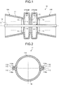
- FIG. 1 is a schematic cross sectional view of a turbine, to which a pressure vessel according to the embodiment is applied.
- FIG. 2 is a cross sectional view of a casing in the turbine, to which the pressure vessel according to this embodiment is applied.
- the turbine illustrated in FIG. 1 exemplifies a steam turbine 10.
- the steam turbine 10 has a casing 11 and a rotor 12.
- the casing 11 is the pressure vessel of this embodiment, and is formed in a cylindrical shape.
- This casing 11 is divided into two parts in a radial direction, as illustrated in FIG. 2 , and flanges 11C protruding outward in the radial direction are provided at divided ends 11Aa and 11Ba of both divided casings 11A and 11B.
- the flanges 11C at a divided casing 11A side and a divided casing 11B side are abutted against each other, and are connected to each other, for example, by fastening with a bolt 11D.
- the casing 11 is formed in the cylindrical shape with both of the divided casings 11A and 11B. Since the rotor 12 is hung by a crane when the rotor 12 is taken into and out from the casing 11, the casing 11 is normally configured to be vertically divided into the divided casings 11A and 11B such that an upper half portion thereof is able to made open. Further, the flanges 11C are formed continuously along a center axis direction, which is an extending direction of a center axis S of the cylindrical shape.
- the rotor 12 is arranged inside the casing 11.
- a shaft center of the rotor 12 is arranged on the center axis S of the cylindrical shape of the casing 11, and is provided to be rotatable around the shaft center.
- the rotor 12 has plural turbine blades 13 extending out in a radial direction of the cylindrical shape and arranged in a circumferential direction toward an inner peripheral surface of the casing 11.
- plural turbine vanes 14 forming counterparts of the turbine blades 13 extend out from the inner peripheral surface toward the rotor 12, and are arranged in the circumferential direction.
- the steam turbine 10 illustrated in FIG. 1 illustrates, as an example, a structure, in which steam is supplied from the center axis direction center of the casing 11 and steam is respectively supplied to both sides separated at the center of the rotor 12 via a seal portion 15. That is, the steam turbine 10 illustrated in FIG. 1 is integrally formed of a first turbine 10A and a second turbine 10B for the single casing 11 and the single rotor 12. In each of the turbines 10A and 10B, motive power is obtained by the turbine blades 13 rotating the rotor 12 by passage of the steam supplied to the casing 11, the passage being between the turbine blades 13 and the turbine vanes 14, and power generation is performed by, for example, a generator (illustration thereof being omitted) connected to the rotor 12.
- a generator illustratedration thereof being omitted
- the turbine may be, although not clearly illustrated in the drawings, a gas turbine.
- the gas turbine also has a casing and a rotor, the casing is the pressure vessel of this embodiment, a cylindrical shape thereof is divided into two parts in a radial direction thereof, flanges protruding outward in the radial direction are provided at divided ends of both of divided casings, and the casing is formed in the cylindrical shape with both the divided casings by connection between these flanges.
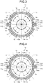
- FIG. 3 and FIG. 4 are cross sectional views of the pressure vessel according to the embodiment.
- the above described casing 11 has increased thickness portions 1 formed therein.
- the increased thickness portions 1 are provided in a portion excluding: the divided ends 11Aa and 11Ba of the divided casings 11A and 11B in which the flanges 11C are provided; and circular arc center portions 11Ab and 11Bb farthest from the divided ends 11Aa and 11Ba; the portion being between the divided ends 11Aa and 11Ba and circular arc center portions 11Ab and 11Bb, and are provided outward in the radial direction of the casing 11 so as to increase radial direction thickness of that portion.
- These increased thickness portions 1 may be the same as, or different from a material forming the casing 11.
- the increased thickness portions 1 are provided symmetrically to each other with reference to center positions C between the divided ends 11Aa and 11Ba and the circular arc center portions 11Ab and 11Bb.
- the casing 11 has the cylindrical shape, and the divided casings 11A and 11B divide the cylindrical shape into two parts and are divided at 180°. Angles between the divided ends 11Aa and 11Ba of the divided casings 11A and 11B and the circular arc center portions 11Ab and 11Bb are 90°, and the center positions C therebetween are at 45° positions.
- the increased thickness portions 1 are formed such that lengths thereof from the center positions C at these 45° positions to respective end portions 1a thereof at divided end 11Aa and 11Ba sides and at circular arc center portion 11Ab and 11Bb sides are equal to each other.
- the increased thickness portions 1 are formed such that radial direction thickness T thereof from the center positions C to the respective end portions 1A is uniform. Furthermore, the increased thickness portions 1 are provided at two positions symmetrical to each other with reference to the circular arc center portion 11Ab or 11Bb of the divided casing 11A or 11B, and are provided at four equal positions in the cylindrical shape of the casing 11.
- the increased thickness portion 1 is provided, as illustrated in FIG. 4 , such that both of the end portions 1a thereof gradually increase in thickness toward the center position C. As illustrated in FIG. 4 , the increased thickness portion 1 is formed such that the radial direction thickness T thereof is uniform excluding the respective end portions 1a. Or, although not illustrated clearly in the drawings, the increased thickness portion 1 may be provided such that thickness thereof is gradually increased from both of the end portions 1a thereof to the center position C, and formed such that the increased thickness portion 1 becomes the thickest at the center position C.
- These increased thickness portions 1 are provided continuously along the center axis direction of the cylindrical shape of the casing 11.
- FIG. 5 is a diagram illustrating functions of a pressure vessel, to which this embodiment has not been applied.
- FIG. 6 is a diagram illustrating functions of a pressure vessel of a comparative example.
- FIG. 7 is a diagram illustrating functions of the pressure vessel according to the embodiment of the present invention.
- FIG. 5 to FIG. 7 each illustrate a case where vertically long deformation is caused in the casing 11.
- the casing 11 is perfectly circular as illustrated with a broken line G1, and upon operation, by supply of high temperature fluid into the casing 11, temperature of the inner peripheral surface thereof is increased and a temperature difference between the inner peripheral surface and an outer peripheral surface thereof is caused.
- the temperature difference is caused, without the flanges 11C, since the amounts of curvature, in which outward curvature is caused by a thermal expansion difference, become equal in the circumferential direction; due to the balance being kept among the amounts of curvature, although deformation is caused outward in the radial direction, the circularity is maintained.
- the casing 11 is divided into the divided casings 11A and 11B and these are formed into the cylindrical shape, the flanges 11C protruding outward in the radial direction are provided at the divided ends 11Aa and 11Ba.
- the flanges 11C protruding outward in the radial direction are provided like this, if a temperature difference between the inner peripheral surface and the outer peripheral surface is caused due to the increase in temperature of the inner peripheral surface, because the thickness between the inner peripheral surface and the outer peripheral surface of the portion at the flanges 11C is large, the thermal expansion difference is increased, and the amount of curvature there, in which outward curvature is caused, becomes larger than that in the other part.
- the increased thickness portions 1 are provided at the center positions C. Therefore, since the thickness between the inner peripheral surfaces and the outer peripheral surfaces at the center positions C is large, the thermal expansion difference is increased, and the amounts of curvature there, in which outward curvature is caused, become nearly equal to that of the portion at the flanges 11C.
- the amount of curvature of the portion at the flanges 11C is reduced, and the amounts of curvature at the respective increased thickness portions 1 symmetrically positioned to each other with reference to the circular arc center portions 11Ab and 11Bb balance each other in the respective divided casings 11A and 11B, and thus deformation of the circular arc center portions 11Ab and 11Bb outward in the radial direction is reduced. Accordingly, due to functions different from those of the comparative example, the circularity is maintained although vertically long deformation is caused outward in the radial direction as illustrated with a thin broken line G4.
- FIG. 8 is a diagram illustrating functions of a pressure vessel, to which this embodiment has not been applied.
- FIG. 9 is a diagram illustrating functions of a pressure vessel of a comparative example.
- FIG. 10 is a diagram illustrating functions of the pressure vessel according to this embodiment.
- FIG. 8 to FIG. 10 each illustrate a case where horizontally long deformation is caused in the casing 11.
- the casing 11 is perfectly circular as illustrated with the broken line G1.
- the amounts of outward curvature in the circular arc center portions 11Ab and 11Bb of the respective divided casings 11A and 11B become larger than that in the other part, and due to the thermal expansion difference in the center axis direction, vertical collapse occurs and horizontally long deformation long in the horizontal direction is caused as illustrated with a solid line G5.
- the increased thickness portions 1 are provided at the center positions C. Therefore, since the thickness between the inner peripheral surfaces and the outer peripheral surfaces at the center positions C is large, the thermal expansion difference is increased, and the amounts of curvature there, in which outward curvature is caused, become nearly equal to that of the circular arc center portions 11Ab and 11Bb.
- the increased thickness portions 1 are formed in the portion excluding the divided ends 11Aa and 11Ba and the circular arc center portions 11Ab and 11Bb farthest from the divided ends 11Aa and 11Ba, the portion being between the divided ends 11Aa and 11Ba and the circular arc center portions 11Ab and 11Bb, the increased thickness portions 1 increasing the thickness thereof in the radial direction.
- both the divided ends 11Aa and 11Ba connected via the flanges 11C are deformed outward in the radial direction and the circular arc center portions 11Ab and 11Bb are deformed inward in the radial direction; by the function for reduction of the amounts of curvature of the circular arc center portions 11Ab and 11Bb through the thermal expansion difference between the inner peripheral surface and the outer peripheral surface of the portion where the increased thickness portions 1 have been provided, and by reduction of the deformation of both the divided ends 11Aa and 11Ba outward in the radial direction through the balance between the amounts of curvature in the respective increased thickness portions 1 symmetrically positioned with reference to both the divided ends 11Aa and 11Ba, the circularity is maintained. As a result, the circularity is able to be improved.
- the increased thickness portions 1 are provided symmetrically with reference to the center positions C between the divided ends 11Aa and 11Ba and the circular arc center portions 11Ab and 11Bb.
- the increased thickness portions 1 are provided such that the thickness of both the end portions 1a thereof is gradually increased toward the center positions C between the divided ends 11Aa and 11Ba and the circular arc center portions 11Ab and 11Bb.
- the increased thickness portions 1 are provided continuously along the center axis direction of the cylindrical shape.
- the effect of improving the circularity is able to be obtained continuously along the center axis direction of the cylindrical shape.
- the above described casing 11 is applied to the steam turbine 10, in which the rotor 12 is rotatably provided inside the casing 11.
- both the divided ends 11Aa and 11Ba connected via the flanges 11C are deformed outward in the radial direction and the circular arc center portions 11Ab and 11Bb are deformed inward in the radial direction; by the function for reduction of the amounts of curvature of the circular arc center portions 11Ab and 11Bb through the thermal expansion difference between the inner peripheral surface and the outer peripheral surface of the portion where the increased thickness portions 1 have been provided, and by reduction of the deformation of both the divided ends 11Aa and 11Ba outward in the radial direction through the balance between the amounts of curvature in the respective increased thickness portions 1 symmetrically positioned with reference to both the divided ends 11Aa and 11Ba, the circularity is maintained.
- the circularity is able to be improved.
- the situation where the gap between the turbine blades 13 provided in the rotor 12 and the inner peripheral surface of the casing 11 is increased is able to be prevented, and the efficiency of the turbine is able to be improved.
Landscapes
- Engineering & Computer Science (AREA)
- General Engineering & Computer Science (AREA)
- Mechanical Engineering (AREA)
- Chemical & Material Sciences (AREA)
- Combustion & Propulsion (AREA)
- Physics & Mathematics (AREA)
- Fluid Mechanics (AREA)
- Pressure Vessels And Lids Thereof (AREA)
- Turbine Rotor Nozzle Sealing (AREA)
Abstract
In order to improve circularity in a casing (11) the cylindrical shape of which is divided into two parts in the radial direction, with the two divided ends (11Aa, 11Ba) being connected in the cylindrical shape by means of flanges (11C) protruding toward the outside in the radial direction, thickness-increasing parts (1), which are for increasing the thickness in the radial direction except at the two divided ends (11Aa, 11Ba) and the arc-shaped center sections (11Ab, 11Bb) farthest from the respective divided ends (11Aa, 11Ba), are formed between the two divided ends (11Aa, 11Ba) and the arc-shaped center sections (11Ab, 11Bb).
Description
- The present invention relates to a pressure vessel, and to a turbine, to which the pressure vessel is applied.
- Conventionally, for example, in
Patent Literature 1, a casing of a steam turbine or a gas turbine has been disclosed. In this casing: flanges are provided at both ends thereof in a structure thereof divided into two parts; a shell upper portion having a center portion with its thickness having been reinforced largely is provided; and thickness of a lower portion of the shell at a position close to the flanges is kept thin; and thereby, during operation, deformation is caused in the lower portion only, whereas deformation in the other most part thereof is made small. - Patent Literature 1: Specification of
U.S. Patent No. 6336789 - In a turbine, such as a steam turbine or a gas turbine: a pressure vessel forming a casing serving as an outer shell of the turbine is formed in a transversely placed cylinder shape, and is vertically divided into two parts; respective flanges thereof extending outward in a radial direction thereof at respective side portions thereof are fastened by bolts and the like; and a rotor, in which turbine blades are arranged around the rotor, is arranged at a center inside the turbine. When this turbine is in operation, that is: for a steam turbine, when steam is being supplied into the pressure vessel and the rotor is rotating; or for a gas turbine, when the rotor of the turbine is being rotated by combustion gas resulting from combustion, by a combustor, of air that has been compressed by a compressor; temperature and pressure inside the pressure vessel become high.
- Since flange portions of the pressure vessel protrude from the side portions, thickness of the pressure vessel at the flange portions is thick. Thus, since at the flange portions, a thermal expansion difference between an inner surface side and an outer surface side thereof is large and force attempting to curve outward is large there as compared to the other part, the whole pressure vessel collapses at the right and left thereof and undergoes vertically long deformation vertically long.
- When thickness of an upper portion and a lower portion is increased like in the above mentioned
Patent Literature 1, in the upper portion and the lower portion, like in flange portions, a thermal expansion difference between an inner surface side and an outer surface side thereof is increased and force attempting to curve outward is increased, and thus the vertically long deformation is prevented. - However, the turbine undergoes a phenomenon, in which its rotor thermally expands in an axial direction, along which the rotor extends. In this case, the pressure vessel collapses at the top and the bottom thereof, and undergoes horizontally long deformation horizontally long. This phenomenon tends to occur at end portions of the pressure vessel. Since the invention described in the above mentioned
Patent Literature 1 is for preventing the vertically long deformation, as to the horizontally long deformation, the invention will function so as to cause more horizontally long deformation. - Such vertically long deformation and horizontally long deformation increase a gap between the turbine blades provided in the rotor and an inner peripheral surface of the casing in the turbine, and thus become a factor that reduces efficiency of the turbine.
- The present invention solves the above described problems, and an object thereof is to provide a pressure vessel and a turbine that enable vertically long deformation and horizontally long deformation thereof to be reduced and circularity thereof to be improved.
- To achieve the above described object, in a pressure vessel according to the present invention, a cylindrical shape thereof is divided into two parts in a radial direction thereof, and the pressure vessel is connected in the cylindrical shape via flanges protruding outward in the radial direction at both divided ends thereof. Increased thickness portions that increase radial direction thickness thereof are formed in a portion excluding the divided ends and circular arc center portions farthest from the divided ends, the portion being between the divided ends and the circular arc center portions.
- According to this pressure vessel, with respect to the form, in which, due to the circumferential direction thermal expansion difference, the circular arc center portions are deformed outward in the radial direction and both the divided ends connected via the flanges are deformed inward in the radial direction; by the function for reduction of the amounts of curvature of both the divided ends through the thermal expansion difference between the inner peripheral surface and the outer peripheral surface of the portion where the increased thickness portions have been provided, and by reduction of the deformation of the circular arc center portions outward in the radial direction through the balance between the amounts of curvature in the respective increased thickness portions symmetrically positioned with reference to the circular arc center portions, the circularity is maintained. With respect to the form, in which, due to the center axis direction thermal expansion difference, both the divided ends connected via the flanges are deformed outward in the radial direction and the circular arc center portions are deformed inward in the radial direction; by the function for reduction of the amounts of curvature of the circular arc center portions through the thermal expansion difference between the inner peripheral surface and the outer peripheral surface of the portion where the increased thickness portions have been provided, and by reduction of the deformation of both the divided ends outward in the radial direction through the balance between the amounts of curvature in the respective increased thickness portions symmetrically positioned with reference to both the divided ends, the circularity is maintained. As a result, the circularity is able to be improved.
- Further, in the pressure vessel according to the present invention, the increased thickness portions are provided symmetrically with reference to center positions between the divided ends and the circular arc center portions.
- According to this pressure vessel, by the increased thickness portions being arranged at symmetrical positions of the cylindrical shape, the balance among the amounts of curvature due to the thermal expansion differences in the respective increased thickness portions is achieved well, and the effect of improving the circularity is able to be obtained prominently.
- Further, in the pressure vessel according to the present invention, the increased thickness portions are provided such that thickness of both end portions thereof is gradually increased toward center positions between the divided ends and the circular arc center portions.
- According to this pressure vessel, by the amounts of curvature due to the thermal expansion differences in the respective increased thickness portions being gradually increased toward the center positions, the situation where extreme differences among the amounts of curvature are caused is prevented, and thus the effect of improving the circularity is able to be obtained prominently.
- Further, in the pressure vessel according to the present invention, the increased thickness portions are provided continuously along a center axis direction of the cylindrical shape.
- According to this pressure vessel, the effect of improving the circularity is able to be obtained continuously along the center axis direction of the cylindrical shape.
- To achieve the above described object, in a turbine according to the present invention, a rotor is rotatably provided inside a casing. Any one of the above described pressure vessels is applied to the casing.
- According to this turbine, with respect to the form, in which, due to the circumferential direction thermal expansion difference, the circular arc center portions are deformed outward in the radial direction and both the divided ends connected via the flanges are deformed inward in the radial direction; by the function for reduction of the amounts of curvature of both the divided ends through the thermal expansion difference between the inner peripheral surface and the outer peripheral surface in the portion where the increased thickness portions have been provided, and by reduction of the deformation of the circular arc center portions outward in the radial direction through the balance between the amounts of curvature in the respective increased thickness portions symmetrically positioned with reference to the circular arc center portions, the circularity is maintained. With respect to the form, in which, due to the center axis direction thermal expansion difference, both the divided ends connected via the flanges are deformed outward in the radial direction and the circular arc center portions are deformed inward in the radial direction; by the function for reduction of the amounts of curvature of the circular arc center portions through the thermal expansion difference between the inner peripheral surface and the outer peripheral surface of the portion where the increased thickness portions have been provided, and by reduction of the deformation of both the divided ends outward in the radial direction through the balance between the amounts of curvature in the respective increased thickness portions symmetrically positioned with reference to both the divided ends, the circularity is maintained. As a result, the circularity is able to be improved. By the improvement of the circularity, the situation where the gap between the turbine blades provided in the rotor and the inner peripheral surface of the casing is increased is able to be prevented, and the efficiency of the turbine is able to be improved.
- According to the present invention, circularity is able to be improved.
-
-
FIG. 1 is a schematic cross sectional view of a turbine, to which a pressure vessel according to an embodiment of the present invention is applied. -
FIG. 2 is a cross sectional view of a casing in the turbine, to which the pressure vessel according to the embodiment of the present invention is applied. -
FIG. 3 is a cross sectional view of the pressure vessel according to the embodiment of the present invention. -
FIG. 4 is a cross sectional view of the pressure vessel according to the embodiment of the present invention. -
FIG. 5 is a diagram illustrating functions of a pressure vessel, to which the embodiment of the present invention has not been applied. -
FIG. 6 is a diagram illustrating functions of a pressure vessel of a comparative example. -
FIG. 7 is a diagram illustrating functions of the pressure vessel according to the embodiment of the present invention. -
FIG. 8 is a diagram illustrating functions of a pressure vessel, to which the embodiment of the present invention has not been applied. -
FIG. 9 is a diagram illustrating functions of a pressure vessel of a comparative example. -
FIG. 10 is a diagram illustrating functions of the pressure vessel according to the embodiment of the present invention. - Hereinafter, an embodiment according to the present invention will be described in detail, based on the drawings. The present invention is not limited by this embodiment. Further, components in the embodiment described below include any component easily substitutable by those skilled in the art or any component substantially identical thereto.
-
FIG. 1 is a schematic cross sectional view of a turbine, to which a pressure vessel according to the embodiment is applied.FIG. 2 is a cross sectional view of a casing in the turbine, to which the pressure vessel according to this embodiment is applied. - The turbine illustrated in
FIG. 1 exemplifies asteam turbine 10. Thesteam turbine 10 has acasing 11 and arotor 12. Thecasing 11 is the pressure vessel of this embodiment, and is formed in a cylindrical shape. Thiscasing 11 is divided into two parts in a radial direction, as illustrated inFIG. 2 , andflanges 11C protruding outward in the radial direction are provided at divided ends 11Aa and 11Ba of both dividedcasings flanges 11C at a dividedcasing 11A side and a dividedcasing 11B side are abutted against each other, and are connected to each other, for example, by fastening with abolt 11D. By the connection between theseflanges 11C, thecasing 11 is formed in the cylindrical shape with both of the dividedcasings rotor 12 is hung by a crane when therotor 12 is taken into and out from thecasing 11, thecasing 11 is normally configured to be vertically divided into the dividedcasings flanges 11C are formed continuously along a center axis direction, which is an extending direction of a center axis S of the cylindrical shape. - The
rotor 12 is arranged inside thecasing 11. A shaft center of therotor 12 is arranged on the center axis S of the cylindrical shape of thecasing 11, and is provided to be rotatable around the shaft center. Further, therotor 12 hasplural turbine blades 13 extending out in a radial direction of the cylindrical shape and arranged in a circumferential direction toward an inner peripheral surface of thecasing 11. At acasing 11 side,plural turbine vanes 14 forming counterparts of theturbine blades 13 extend out from the inner peripheral surface toward therotor 12, and are arranged in the circumferential direction. - The
steam turbine 10 illustrated inFIG. 1 illustrates, as an example, a structure, in which steam is supplied from the center axis direction center of thecasing 11 and steam is respectively supplied to both sides separated at the center of therotor 12 via aseal portion 15. That is, thesteam turbine 10 illustrated inFIG. 1 is integrally formed of afirst turbine 10A and asecond turbine 10B for thesingle casing 11 and thesingle rotor 12. In each of theturbines turbine blades 13 rotating therotor 12 by passage of the steam supplied to thecasing 11, the passage being between theturbine blades 13 and theturbine vanes 14, and power generation is performed by, for example, a generator (illustration thereof being omitted) connected to therotor 12. - Further, the turbine may be, although not clearly illustrated in the drawings, a gas turbine. The gas turbine also has a casing and a rotor, the casing is the pressure vessel of this embodiment, a cylindrical shape thereof is divided into two parts in a radial direction thereof, flanges protruding outward in the radial direction are provided at divided ends of both of divided casings, and the casing is formed in the cylindrical shape with both the divided casings by connection between these flanges.
-
FIG. 3 and FIG. 4 are cross sectional views of the pressure vessel according to the embodiment. - The above described casing 11 has increased
thickness portions 1 formed therein. The increasedthickness portions 1 are provided in a portion excluding: the divided ends 11Aa and 11Ba of the dividedcasings flanges 11C are provided; and circular arc center portions 11Ab and 11Bb farthest from the divided ends 11Aa and 11Ba; the portion being between the divided ends 11Aa and 11Ba and circular arc center portions 11Ab and 11Bb, and are provided outward in the radial direction of thecasing 11 so as to increase radial direction thickness of that portion. These increasedthickness portions 1 may be the same as, or different from a material forming thecasing 11. - Further, the increased
thickness portions 1 are provided symmetrically to each other with reference to center positions C between the divided ends 11Aa and 11Ba and the circular arc center portions 11Ab and 11Bb. Thecasing 11 has the cylindrical shape, and the dividedcasings casings thickness portions 1 are formed such that lengths thereof from the center positions C at these 45° positions torespective end portions 1a thereof at divided end 11Aa and 11Ba sides and at circular arc center portion 11Ab and 11Bb sides are equal to each other. - Further, the increased
thickness portions 1 are formed such that radial direction thickness T thereof from the center positions C to the respective end portions 1A is uniform. Furthermore, the increasedthickness portions 1 are provided at two positions symmetrical to each other with reference to the circular arc center portion 11Ab or 11Bb of the dividedcasing casing 11. - Further, the increased
thickness portion 1 is provided, as illustrated inFIG. 4 , such that both of theend portions 1a thereof gradually increase in thickness toward the center position C. As illustrated inFIG. 4 , the increasedthickness portion 1 is formed such that the radial direction thickness T thereof is uniform excluding therespective end portions 1a. Or, although not illustrated clearly in the drawings, the increasedthickness portion 1 may be provided such that thickness thereof is gradually increased from both of theend portions 1a thereof to the center position C, and formed such that the increasedthickness portion 1 becomes the thickest at the center position C. - These increased
thickness portions 1 are provided continuously along the center axis direction of the cylindrical shape of thecasing 11. - Hereinafter, functions of the increased
thickness portions 1 will be described. First, vertically long deformation will be described.FIG. 5 is a diagram illustrating functions of a pressure vessel, to which this embodiment has not been applied.FIG. 6 is a diagram illustrating functions of a pressure vessel of a comparative example.FIG. 7 is a diagram illustrating functions of the pressure vessel according to the embodiment of the present invention. -
FIG. 5 to FIG. 7 each illustrate a case where vertically long deformation is caused in thecasing 11. As illustrated inFIG. 5 , normally, thecasing 11 is perfectly circular as illustrated with a broken line G1, and upon operation, by supply of high temperature fluid into thecasing 11, temperature of the inner peripheral surface thereof is increased and a temperature difference between the inner peripheral surface and an outer peripheral surface thereof is caused. When the temperature difference is caused, without theflanges 11C, since the amounts of curvature, in which outward curvature is caused by a thermal expansion difference, become equal in the circumferential direction; due to the balance being kept among the amounts of curvature, although deformation is caused outward in the radial direction, the circularity is maintained. - However, since the
casing 11 is divided into the dividedcasings flanges 11C protruding outward in the radial direction are provided at the divided ends 11Aa and 11Ba. When theflanges 11C protruding outward in the radial direction are provided like this, if a temperature difference between the inner peripheral surface and the outer peripheral surface is caused due to the increase in temperature of the inner peripheral surface, because the thickness between the inner peripheral surface and the outer peripheral surface of the portion at theflanges 11C is large, the thermal expansion difference is increased, and the amount of curvature there, in which outward curvature is caused, becomes larger than that in the other part. Therefore, the balance among the amounts of curvature is lost, and the portion at the divided ends 11Aa and 11Ba connected via theflanges 11C attempts to curve outward largely, and thus vertically long deformation is caused as illustrated with a solid line G2 due to the thermal expansion difference in the circumferential direction. - In a case where, for example, the thickness of the circular arc center portions 11Ab and 11Bb of the divided
casings Patent Literature 1 against such vertically long deformation illustrated inFIG. 5 , the case being the comparative example illustrated inFIG. 6 , since the thickness between the inner peripheral surface and the outer peripheral surface of the circular arc center portions 11Ab and 11Bb is large, it will be assumed that the thermal expansion difference is increased, and the amount of curvature there, in which outward curvature is caused, becomes equal to that of the portions at theflanges 11C. Since the amounts of curvature in the circular arc center portions 11Ab and 11Bb and in the portion at theflanges 11C balance each other, the circularity is maintained although vertically long deformation is caused outward in the radial direction as illustrated with a thin broken line G3. - Meanwhile, in the pressure vessel of this embodiment illustrated in
FIG. 7 , the increasedthickness portions 1 are provided at the center positions C. Therefore, since the thickness between the inner peripheral surfaces and the outer peripheral surfaces at the center positions C is large, the thermal expansion difference is increased, and the amounts of curvature there, in which outward curvature is caused, become nearly equal to that of the portion at theflanges 11C. Due to the curvature at the center positions C, the amount of curvature of the portion at theflanges 11C is reduced, and the amounts of curvature at the respective increasedthickness portions 1 symmetrically positioned to each other with reference to the circular arc center portions 11Ab and 11Bb balance each other in the respective dividedcasings - Next, horizontally long deformation will be described.
FIG. 8 is a diagram illustrating functions of a pressure vessel, to which this embodiment has not been applied.FIG. 9 is a diagram illustrating functions of a pressure vessel of a comparative example.FIG. 10 is a diagram illustrating functions of the pressure vessel according to this embodiment. -
FIG. 8 to FIG. 10 each illustrate a case where horizontally long deformation is caused in thecasing 11. As illustrated inFIG. 8 , normally, thecasing 11 is perfectly circular as illustrated with the broken line G1. When thermal expansion occurs in the center axis direction of the cylindrical shape, the amounts of outward curvature in the circular arc center portions 11Ab and 11Bb of the respective dividedcasings - In a case where, for example, the thickness of the circular arc center portions 11Ab and 11Bb of the divided
casings Patent Literature 1 against such horizontally long deformation illustrated inFIG. 8 , the case being the comparative example illustrated inFIG. 9 , since the thickness between the inner peripheral surface and the outer peripheral surface of the circular arc center portions 11Ab and 11Bb is large, the thermal expansion difference is increased, and the amounts of curvature there, in which outward curvature is caused, become even larger as compared to that of the other part. Accordingly, the horizontally long deformation is increased as illustrated with a thin broken line G6. - Meanwhile, in the pressure vessel of this embodiment illustrated in
FIG. 10 , the increasedthickness portions 1 are provided at the center positions C. Therefore, since the thickness between the inner peripheral surfaces and the outer peripheral surfaces at the center positions C is large, the thermal expansion difference is increased, and the amounts of curvature there, in which outward curvature is caused, become nearly equal to that of the circular arc center portions 11Ab and 11Bb. Since the amounts of curvature of the circular arc center portions 11Ab and 11Bb are reduced by the curvature at the center positions C, and the amounts of curvature in the respective increasedthickness portions 1 symmetrically positioned with reference to the divided ends 11Aa and 11Ba connected via theflanges 11C balance each other between the dividedcasings - As described above, according to the casing (pressure vessel) 11 of this embodiment, in the
casing 11, in which the cylindrical shape thereof is divided into two parts in the radial direction, and which is connected in the cylindrical shape via theflanges 11C protruding outward in the radial direction at both of the divided ends 11Aa and 11Ba, the increasedthickness portions 1 are formed in the portion excluding the divided ends 11Aa and 11Ba and the circular arc center portions 11Ab and 11Bb farthest from the divided ends 11Aa and 11Ba, the portion being between the divided ends 11Aa and 11Ba and the circular arc center portions 11Ab and 11Bb, the increasedthickness portions 1 increasing the thickness thereof in the radial direction. - According to this
casing 11, with respect to the form, in which, due to the circumferential direction thermal expansion difference, the circular arc center portions 11Ab and 11Bb are deformed outward in the radial direction and both the divided ends 11Aa and 11Ba connected via theflanges 11C are deformed inward in the radial direction; by the function for reduction of the amounts of curvature of both the divided ends 11Aa and 11Ba through the thermal expansion difference between the inner peripheral surface and the outer peripheral surface of the portion where the increasedthickness portions 1 have been provided, and by reduction of the deformation of the circular arc center portions 11Ab and 11Bb outward in the radial direction through the balance between the amounts of curvature in the respective increasedthickness portions 1 symmetrically positioned with reference to the circular arc center portions 11Ab and 11Bb, the circularity is maintained. with respect to the form in which, due to the center axis direction thermal expansion difference, both the divided ends 11Aa and 11Ba connected via theflanges 11C are deformed outward in the radial direction and the circular arc center portions 11Ab and 11Bb are deformed inward in the radial direction; by the function for reduction of the amounts of curvature of the circular arc center portions 11Ab and 11Bb through the thermal expansion difference between the inner peripheral surface and the outer peripheral surface of the portion where the increasedthickness portions 1 have been provided, and by reduction of the deformation of both the divided ends 11Aa and 11Ba outward in the radial direction through the balance between the amounts of curvature in the respective increasedthickness portions 1 symmetrically positioned with reference to both the divided ends 11Aa and 11Ba, the circularity is maintained. As a result, the circularity is able to be improved. - Further, in the
casing 11 of this embodiment, the increasedthickness portions 1 are provided symmetrically with reference to the center positions C between the divided ends 11Aa and 11Ba and the circular arc center portions 11Ab and 11Bb. - According to this
casing 11, by the increasedthickness portions 1 being arranged at symmetrical positions of the cylindrical shape, the balance among the amounts of curvature due to the thermal expansion differences in the respective increasedthickness portions 1 is achieved, and thus the effect of improving the circularity is able to be obtained prominently. - Further, in the
casing 11 of this embodiment, the increasedthickness portions 1 are provided such that the thickness of both theend portions 1a thereof is gradually increased toward the center positions C between the divided ends 11Aa and 11Ba and the circular arc center portions 11Ab and 11Bb. - According to this
casing 11, by the amounts of curvature due to the thermal expansion differences in the respective increasedthickness portions 1 being gradually increased toward the center positions C, the situation where extreme differences among the amounts of curvature are caused is prevented, and thus the effect of improving the circularity is able to be obtained prominently. - Further, in the
casing 11 of this embodiment, the increasedthickness portions 1 are provided continuously along the center axis direction of the cylindrical shape. - According to this
casing 11, the effect of improving the circularity is able to be obtained continuously along the center axis direction of the cylindrical shape. - Further, according to the steam turbine (turbine) 10 of this embodiment, the above described
casing 11 is applied to thesteam turbine 10, in which therotor 12 is rotatably provided inside thecasing 11. - According to this
steam turbine 10, with respect to the form, in which, due to the circumferential direction thermal expansion difference, the circular arc center portions 11Ab and 11Bb are deformed outward in the radial direction and both the divided ends 11Aa and 11Ba connected via theflanges 11C are deformed inward in the radial direction; by the function for reduction of the amounts of curvature of both the divided ends 11Aa and 11Ba through the thermal expansion difference between the inner peripheral surface and the outer peripheral surface of the portion where the increasedthickness portions 1 have been provided, and by reduction of the deformation of the circular arc center portions 11Ab and 11Bb outward in the radial direction through the balance between the amounts of curvature in the respective increasedthickness portions 1 symmetrically positioned with reference to the circular arc center portions 11Ab and 11Bb, the circularity is maintained. Meanwhile, with respect to the form, in which, due to the center axis direction thermal expansion difference, both the divided ends 11Aa and 11Ba connected via theflanges 11C are deformed outward in the radial direction and the circular arc center portions 11Ab and 11Bb are deformed inward in the radial direction; by the function for reduction of the amounts of curvature of the circular arc center portions 11Ab and 11Bb through the thermal expansion difference between the inner peripheral surface and the outer peripheral surface of the portion where the increasedthickness portions 1 have been provided, and by reduction of the deformation of both the divided ends 11Aa and 11Ba outward in the radial direction through the balance between the amounts of curvature in the respective increasedthickness portions 1 symmetrically positioned with reference to both the divided ends 11Aa and 11Ba, the circularity is maintained. As a result, the circularity is able to be improved. By the improvement of the circularity, the situation where the gap between theturbine blades 13 provided in therotor 12 and the inner peripheral surface of thecasing 11 is increased is able to be prevented, and the efficiency of the turbine is able to be improved. -
- 1
- INCREASED THICKNESS PORTION
- 1a
- END PORTION
- 10, 10A, 10B
- STEAM TURBINE (TURBINE)
- 11
- CASING (PRESSURE VESSEL)
- 11A, 11B
- DIVIDED CASING
- 11Aa, 11Ba
- DIVIDED END
- 11Ab, 11Bb
- CENTER PORTION
- 11C
- FLANGE
- 11D
- BOLT
- 12
- ROTOR
- 13
- TURBINE BLADE
- 14
- TURBINE VANE
- 15
- SEAL PORTION
- C
- CENTER POSITION
- S
- CENTER AXIS
Claims (5)
- A pressure vessel, in which a cylindrical shape thereof is divided into two parts in a radial direction thereof, and the pressure vessel is connected in the cylindrical shape via flanges protruding outward in the radial direction at both divided ends thereof, wherein
increased thickness portions that increase radial direction thickness thereof are formed in a portion excluding the divided ends and circular arc center portions farthest from the divided ends, the portion being between the divided ends and the circular arc center portions. - The pressure vessel according to claim 1, wherein the increased thickness portions are provided symmetrically with reference to center positions between the divided ends and the circular arc center portions.
- The pressure vessel according to claim 1 or 2, wherein
the increased thickness portions are provided such that thickness of both end portions thereof is gradually increased toward center positions between the divided ends and the circular arc center portions. - The pressure vessel according to any one of claims 1 to 3, wherein the increased thickness portions are provided continuously along a center axis direction of the cylindrical shape.
- A turbine, in which a rotor is rotatably provided inside a casing, wherein
the pressure vessel according to any one of claims 1 to 4 is applied to the casing.
Applications Claiming Priority (2)
| Application Number | Priority Date | Filing Date | Title |
|---|---|---|---|
| JP2014254453A JP2016113992A (en) | 2014-12-16 | 2014-12-16 | Pressure container and turbine |
| PCT/JP2015/074060 WO2016098393A1 (en) | 2014-12-16 | 2015-08-26 | Pressure vessel and turbine |
Publications (1)
| Publication Number | Publication Date |
|---|---|
| EP3236024A1 true EP3236024A1 (en) | 2017-10-25 |
Family
ID=56126296
Family Applications (1)
| Application Number | Title | Priority Date | Filing Date |
|---|---|---|---|
| EP15869602.1A Withdrawn EP3236024A1 (en) | 2014-12-16 | 2015-08-26 | Pressure vessel and turbine |
Country Status (6)
| Country | Link |
|---|---|
| US (1) | US10400633B2 (en) |
| EP (1) | EP3236024A1 (en) |
| JP (1) | JP2016113992A (en) |
| KR (1) | KR20170083137A (en) |
| CN (1) | CN107002505A (en) |
| WO (1) | WO2016098393A1 (en) |
Cited By (1)
| Publication number | Priority date | Publication date | Assignee | Title |
|---|---|---|---|---|
| CN109252902A (en) * | 2018-09-14 | 2019-01-22 | 中国航发湖南动力机械研究所 | Axial limit structure and turbogenerator |
Families Citing this family (2)
| Publication number | Priority date | Publication date | Assignee | Title |
|---|---|---|---|---|
| CN114017134B (en) * | 2021-11-12 | 2024-12-20 | 中国航发沈阳发动机研究所 | A method for adjusting the thermal deformation rate of a casing by changing the thermal capacity of the casing |
| JP7840162B2 (en) | 2022-01-27 | 2026-04-03 | 三菱重工業株式会社 | Vehicle enclosures and axial flow rotating machinery |
Family Cites Families (8)
| Publication number | Priority date | Publication date | Assignee | Title |
|---|---|---|---|---|
| US2256221A (en) * | 1938-03-18 | 1941-09-16 | Gen Electric | Elastic fluid turbine casing |
| JPS5986753A (en) * | 1982-11-10 | 1984-05-19 | Nissan Motor Co Ltd | Spherical pressure vessel |
| US5605438A (en) * | 1995-12-29 | 1997-02-25 | General Electric Co. | Casing distortion control for rotating machinery |
| DE59909395D1 (en) * | 1999-01-20 | 2004-06-09 | Alstom Technology Ltd Baden | Housing for a steam or gas turbine |
| JP2005042612A (en) | 2003-07-22 | 2005-02-17 | Ishikawajima Harima Heavy Ind Co Ltd | Casing, casing deformation prevention system and method |
| US8128353B2 (en) * | 2008-09-30 | 2012-03-06 | General Electric Company | Method and apparatus for matching the thermal mass and stiffness of bolted split rings |
| US8231338B2 (en) | 2009-05-05 | 2012-07-31 | General Electric Company | Turbine shell with pin support |
| US20130236293A1 (en) | 2012-03-09 | 2013-09-12 | General Electric Company | Systems and methods for an improved stator |
-
2014
- 2014-12-16 JP JP2014254453A patent/JP2016113992A/en active Pending
-
2015
- 2015-08-26 KR KR1020177016310A patent/KR20170083137A/en not_active Ceased
- 2015-08-26 US US15/534,792 patent/US10400633B2/en active Active
- 2015-08-26 CN CN201580066796.3A patent/CN107002505A/en active Pending
- 2015-08-26 EP EP15869602.1A patent/EP3236024A1/en not_active Withdrawn
- 2015-08-26 WO PCT/JP2015/074060 patent/WO2016098393A1/en not_active Ceased
Cited By (1)
| Publication number | Priority date | Publication date | Assignee | Title |
|---|---|---|---|---|
| CN109252902A (en) * | 2018-09-14 | 2019-01-22 | 中国航发湖南动力机械研究所 | Axial limit structure and turbogenerator |
Also Published As
| Publication number | Publication date |
|---|---|
| US10400633B2 (en) | 2019-09-03 |
| JP2016113992A (en) | 2016-06-23 |
| CN107002505A (en) | 2017-08-01 |
| KR20170083137A (en) | 2017-07-17 |
| US20170342861A1 (en) | 2017-11-30 |
| WO2016098393A1 (en) | 2016-06-23 |
Similar Documents
| Publication | Publication Date | Title |
|---|---|---|
| US20170022833A1 (en) | Method and system for interfacing a ceramic matrix composite component to a metallic component | |
| EP2896791A1 (en) | Mistuned airfoil assemblies | |
| US8894368B2 (en) | Device and method for aligning tip shrouds | |
| EP3124743A1 (en) | Nozzle guide vane and method for forming a nozzle guide vane | |
| EP2886801A1 (en) | Seal system for a gas turbine and corresponding gas turbine | |
| US8979498B2 (en) | Turbine airfoil having outboard and inboard sections | |
| US10174636B2 (en) | Compressor assembly for gas turbine | |
| CN107002495A (en) | For the blade for manufacturing the method for rotor blade and obtaining in this way | |
| CN101713303A (en) | Method and apparatus for matching the thermal mass and stiffness of bolted split rings | |
| US10954808B2 (en) | Sealing device and rotary machine | |
| EP2642082A1 (en) | Thermal isolation apparatus | |
| CN106168229A (en) | The blade having socket of compressor and guard shield for axial turbine | |
| US10400633B2 (en) | Pressure vessel and turbine | |
| BR112015025386B1 (en) | Fan disc for a turbojet engine and turbojet engine | |
| EP3034790B1 (en) | Rotating blade for a gas turbine | |
| US10138737B2 (en) | Rotor for turbine engine comprising blades with added platforms | |
| US9097128B2 (en) | Seals for rotary devices and methods of producing the same | |
| EP3034798B1 (en) | Gas turbine vane | |
| WO2017146724A1 (en) | Damping for fabricated hollow turbine blades | |
| EP2995772A1 (en) | Mounting and sealing arrangement for a guide vane of a gas turbine | |
| US20190055849A1 (en) | Laminated airfoil for a gas turbine | |
| EP3358134B1 (en) | Steam turbine with rotor blade | |
| JP6249927B2 (en) | Steam turbine | |
| US20180154429A1 (en) | Method for casting a turbine blade | |
| JP6434780B2 (en) | Rotor assembly for turbine, turbine, and moving blade |
Legal Events
| Date | Code | Title | Description |
|---|---|---|---|
| PUAI | Public reference made under article 153(3) epc to a published international application that has entered the european phase |
Free format text: ORIGINAL CODE: 0009012 |
|
| 17P | Request for examination filed |
Effective date: 20170531 |
|
| AK | Designated contracting states |
Kind code of ref document: A1 Designated state(s): AL AT BE BG CH CY CZ DE DK EE ES FI FR GB GR HR HU IE IS IT LI LT LU LV MC MK MT NL NO PL PT RO RS SE SI SK SM TR |
|
| AX | Request for extension of the european patent |
Extension state: BA ME |
|
| DAV | Request for validation of the european patent (deleted) | ||
| DAX | Request for extension of the european patent (deleted) | ||
| STAA | Information on the status of an ep patent application or granted ep patent |
Free format text: STATUS: THE APPLICATION HAS BEEN WITHDRAWN |
|
| 18W | Application withdrawn |
Effective date: 20180710 |