EP3236008A1 - Systems and methods for producing one or more cooling holes in an airfoil for a gas turbine engine - Google Patents
Systems and methods for producing one or more cooling holes in an airfoil for a gas turbine engine Download PDFInfo
- Publication number
- EP3236008A1 EP3236008A1 EP16199471.0A EP16199471A EP3236008A1 EP 3236008 A1 EP3236008 A1 EP 3236008A1 EP 16199471 A EP16199471 A EP 16199471A EP 3236008 A1 EP3236008 A1 EP 3236008A1
- Authority
- EP
- European Patent Office
- Prior art keywords
- airfoil
- bosses
- holes
- hole starter
- cooling holes
- Prior art date
- Legal status (The legal status is an assumption and is not a legal conclusion. Google has not performed a legal analysis and makes no representation as to the accuracy of the status listed.)
- Granted
Links
Images



Classifications
-
- B—PERFORMING OPERATIONS; TRANSPORTING
- B23—MACHINE TOOLS; METAL-WORKING NOT OTHERWISE PROVIDED FOR
- B23P—METAL-WORKING NOT OTHERWISE PROVIDED FOR; COMBINED OPERATIONS; UNIVERSAL MACHINE TOOLS
- B23P15/00—Making specific metal objects by operations not covered by a single other subclass or a group in this subclass
-
- F—MECHANICAL ENGINEERING; LIGHTING; HEATING; WEAPONS; BLASTING
- F01—MACHINES OR ENGINES IN GENERAL; ENGINE PLANTS IN GENERAL; STEAM ENGINES
- F01D—NON-POSITIVE DISPLACEMENT MACHINES OR ENGINES, e.g. STEAM TURBINES
- F01D5/00—Blades; Blade-carrying members; Heating, heat-insulating, cooling or antivibration means on the blades or the members
- F01D5/12—Blades
- F01D5/14—Form or construction
- F01D5/18—Hollow blades, i.e. blades with cooling or heating channels or cavities; Heating, heat-insulating or cooling means on blades
- F01D5/186—Film cooling
-
- F—MECHANICAL ENGINEERING; LIGHTING; HEATING; WEAPONS; BLASTING
- F01—MACHINES OR ENGINES IN GENERAL; ENGINE PLANTS IN GENERAL; STEAM ENGINES
- F01D—NON-POSITIVE DISPLACEMENT MACHINES OR ENGINES, e.g. STEAM TURBINES
- F01D5/00—Blades; Blade-carrying members; Heating, heat-insulating, cooling or antivibration means on the blades or the members
- F01D5/12—Blades
- F01D5/14—Form or construction
- F01D5/18—Hollow blades, i.e. blades with cooling or heating channels or cavities; Heating, heat-insulating or cooling means on blades
-
- F—MECHANICAL ENGINEERING; LIGHTING; HEATING; WEAPONS; BLASTING
- F01—MACHINES OR ENGINES IN GENERAL; ENGINE PLANTS IN GENERAL; STEAM ENGINES
- F01D—NON-POSITIVE DISPLACEMENT MACHINES OR ENGINES, e.g. STEAM TURBINES
- F01D5/00—Blades; Blade-carrying members; Heating, heat-insulating, cooling or antivibration means on the blades or the members
- F01D5/005—Repairing methods or devices
-
- F—MECHANICAL ENGINEERING; LIGHTING; HEATING; WEAPONS; BLASTING
- F01—MACHINES OR ENGINES IN GENERAL; ENGINE PLANTS IN GENERAL; STEAM ENGINES
- F01D—NON-POSITIVE DISPLACEMENT MACHINES OR ENGINES, e.g. STEAM TURBINES
- F01D5/00—Blades; Blade-carrying members; Heating, heat-insulating, cooling or antivibration means on the blades or the members
- F01D5/12—Blades
- F01D5/22—Blade-to-blade connections, e.g. for damping vibrations
- F01D5/225—Blade-to-blade connections, e.g. for damping vibrations by shrouding
-
- B—PERFORMING OPERATIONS; TRANSPORTING
- B23—MACHINE TOOLS; METAL-WORKING NOT OTHERWISE PROVIDED FOR
- B23B—TURNING; BORING
- B23B2215/00—Details of workpieces
- B23B2215/76—Components for turbines
- B23B2215/81—Turbine blades
-
- F—MECHANICAL ENGINEERING; LIGHTING; HEATING; WEAPONS; BLASTING
- F05—INDEXING SCHEMES RELATING TO ENGINES OR PUMPS IN VARIOUS SUBCLASSES OF CLASSES F01-F04
- F05D—INDEXING SCHEME FOR ASPECTS RELATING TO NON-POSITIVE-DISPLACEMENT MACHINES OR ENGINES, GAS-TURBINES OR JET-PROPULSION PLANTS
- F05D2220/00—Application
- F05D2220/30—Application in turbines
- F05D2220/32—Application in turbines in gas turbines
-
- F—MECHANICAL ENGINEERING; LIGHTING; HEATING; WEAPONS; BLASTING
- F05—INDEXING SCHEMES RELATING TO ENGINES OR PUMPS IN VARIOUS SUBCLASSES OF CLASSES F01-F04
- F05D—INDEXING SCHEME FOR ASPECTS RELATING TO NON-POSITIVE-DISPLACEMENT MACHINES OR ENGINES, GAS-TURBINES OR JET-PROPULSION PLANTS
- F05D2230/00—Manufacture
- F05D2230/10—Manufacture by removing material
-
- F—MECHANICAL ENGINEERING; LIGHTING; HEATING; WEAPONS; BLASTING
- F05—INDEXING SCHEMES RELATING TO ENGINES OR PUMPS IN VARIOUS SUBCLASSES OF CLASSES F01-F04
- F05D—INDEXING SCHEME FOR ASPECTS RELATING TO NON-POSITIVE-DISPLACEMENT MACHINES OR ENGINES, GAS-TURBINES OR JET-PROPULSION PLANTS
- F05D2230/00—Manufacture
- F05D2230/10—Manufacture by removing material
- F05D2230/11—Manufacture by removing material by electrochemical methods
-
- F—MECHANICAL ENGINEERING; LIGHTING; HEATING; WEAPONS; BLASTING
- F05—INDEXING SCHEMES RELATING TO ENGINES OR PUMPS IN VARIOUS SUBCLASSES OF CLASSES F01-F04
- F05D—INDEXING SCHEME FOR ASPECTS RELATING TO NON-POSITIVE-DISPLACEMENT MACHINES OR ENGINES, GAS-TURBINES OR JET-PROPULSION PLANTS
- F05D2230/00—Manufacture
- F05D2230/10—Manufacture by removing material
- F05D2230/14—Micromachining
-
- F—MECHANICAL ENGINEERING; LIGHTING; HEATING; WEAPONS; BLASTING
- F05—INDEXING SCHEMES RELATING TO ENGINES OR PUMPS IN VARIOUS SUBCLASSES OF CLASSES F01-F04
- F05D—INDEXING SCHEME FOR ASPECTS RELATING TO NON-POSITIVE-DISPLACEMENT MACHINES OR ENGINES, GAS-TURBINES OR JET-PROPULSION PLANTS
- F05D2230/00—Manufacture
- F05D2230/20—Manufacture essentially without removing material
- F05D2230/21—Manufacture essentially without removing material by casting
-
- F—MECHANICAL ENGINEERING; LIGHTING; HEATING; WEAPONS; BLASTING
- F05—INDEXING SCHEMES RELATING TO ENGINES OR PUMPS IN VARIOUS SUBCLASSES OF CLASSES F01-F04
- F05D—INDEXING SCHEME FOR ASPECTS RELATING TO NON-POSITIVE-DISPLACEMENT MACHINES OR ENGINES, GAS-TURBINES OR JET-PROPULSION PLANTS
- F05D2230/00—Manufacture
- F05D2230/80—Repairing, retrofitting or upgrading methods
-
- F—MECHANICAL ENGINEERING; LIGHTING; HEATING; WEAPONS; BLASTING
- F05—INDEXING SCHEMES RELATING TO ENGINES OR PUMPS IN VARIOUS SUBCLASSES OF CLASSES F01-F04
- F05D—INDEXING SCHEME FOR ASPECTS RELATING TO NON-POSITIVE-DISPLACEMENT MACHINES OR ENGINES, GAS-TURBINES OR JET-PROPULSION PLANTS
- F05D2240/00—Components
- F05D2240/20—Rotors
- F05D2240/30—Characteristics of rotor blades, i.e. of any element transforming dynamic fluid energy to or from rotational energy and being attached to a rotor
- F05D2240/305—Characteristics of rotor blades, i.e. of any element transforming dynamic fluid energy to or from rotational energy and being attached to a rotor related to the pressure side of a rotor blade
-
- F—MECHANICAL ENGINEERING; LIGHTING; HEATING; WEAPONS; BLASTING
- F05—INDEXING SCHEMES RELATING TO ENGINES OR PUMPS IN VARIOUS SUBCLASSES OF CLASSES F01-F04
- F05D—INDEXING SCHEME FOR ASPECTS RELATING TO NON-POSITIVE-DISPLACEMENT MACHINES OR ENGINES, GAS-TURBINES OR JET-PROPULSION PLANTS
- F05D2240/00—Components
- F05D2240/20—Rotors
- F05D2240/30—Characteristics of rotor blades, i.e. of any element transforming dynamic fluid energy to or from rotational energy and being attached to a rotor
- F05D2240/306—Characteristics of rotor blades, i.e. of any element transforming dynamic fluid energy to or from rotational energy and being attached to a rotor related to the suction side of a rotor blade
-
- F—MECHANICAL ENGINEERING; LIGHTING; HEATING; WEAPONS; BLASTING
- F05—INDEXING SCHEMES RELATING TO ENGINES OR PUMPS IN VARIOUS SUBCLASSES OF CLASSES F01-F04
- F05D—INDEXING SCHEME FOR ASPECTS RELATING TO NON-POSITIVE-DISPLACEMENT MACHINES OR ENGINES, GAS-TURBINES OR JET-PROPULSION PLANTS
- F05D2250/00—Geometry
- F05D2250/50—Inlet or outlet
- F05D2250/52—Outlet
-
- F—MECHANICAL ENGINEERING; LIGHTING; HEATING; WEAPONS; BLASTING
- F05—INDEXING SCHEMES RELATING TO ENGINES OR PUMPS IN VARIOUS SUBCLASSES OF CLASSES F01-F04
- F05D—INDEXING SCHEME FOR ASPECTS RELATING TO NON-POSITIVE-DISPLACEMENT MACHINES OR ENGINES, GAS-TURBINES OR JET-PROPULSION PLANTS
- F05D2260/00—Function
- F05D2260/20—Heat transfer, e.g. cooling
-
- F—MECHANICAL ENGINEERING; LIGHTING; HEATING; WEAPONS; BLASTING
- F05—INDEXING SCHEMES RELATING TO ENGINES OR PUMPS IN VARIOUS SUBCLASSES OF CLASSES F01-F04
- F05D—INDEXING SCHEME FOR ASPECTS RELATING TO NON-POSITIVE-DISPLACEMENT MACHINES OR ENGINES, GAS-TURBINES OR JET-PROPULSION PLANTS
- F05D2260/00—Function
- F05D2260/20—Heat transfer, e.g. cooling
- F05D2260/202—Heat transfer, e.g. cooling by film cooling
Definitions
- Embodiments of the disclosure relate generally to gas turbine engines and more particularly relate to systems and methods for producing one or more cooling holes in an airfoil for a gas turbine engine.
- buckets may be cooled with radial holes that exit (or break out) on a surface of the airfoil rather than running the full length of the airfoil and emerging at the tip.
- Such cooling holes may break out of the airfoil in the shape of a long, narrow, ellipse. It can be very difficult to drill holes into the airfoil at such a shallow angle.
- a method for producing one or more cooling holes in an airfoil for a gas turbine engine may include casting one or more hole starter bosses on a suction side, a pressure side, or both of the airfoil, drilling the one or more cooling holes into the airfoil by way of the one or more hole starter bosses, and removing the one or more hole starter bosses after drilling the one or more cooling holes into the airfoil.
- an airfoil for a gas turbine engine may include a suction side, a pressure side opposite the suction side, and one or more hole starter bosses cast on the suction side, the pressure side, or both.
- a method for producing one or more cooling holes in an airfoil for a gas turbine engine may include casting one or more hole starter bosses on a suction side, a pressure side, or both of the airfoil, drilling one or more line-of-sight access holes in a shroud of the airfoil to provide access to the one or more hole starter bosses, drilling the one or more cooling holes into the airfoil by way of the one or more hole starter bosses, and grinding the one or more hole starter bosses after drilling the one or more cooling holes into the airfoil.
- Illustrative embodiments of the disclosure are directed to, among other things, systems and methods for producing one or more cooling holes in an airfoil for a gas turbine engine.
- one or more hole starter bosses may be cast on a suction side, a pressure side, or both of the airfoil.
- the cooling holes may be drilled into the surface of the suction side or the pressure side of the airfoil.
- the starter bosses may enable a relatively steep drill angle into the surface of the airfoil.
- the hole starter bosses may be removed. For example, the hole starter bosses may be ground off of the surface of the airfoil.
- a shroud at the tip of the airfoil may prevent adequate access to the hole starter bosses.
- the shroud may block the drill angle or the line-of sight of a drill to the hole starter bosses.
- one or more line-of-sight access holes may be drilled or cast into the shroud of the airfoil to provide access to the hole starter bosses. After the cooling holes have been drilled into the surface of the airfoil, the line-of-sight access holes may be filled in.
- the line-of-sight access holes may be sealed by brazing, plugging, welding, or covered with a plate that may be brazed or welded in place.
- the cover could be on either the flowpath side or the seal side of the shroud and could be recessed so as to create a smooth surface. Other means of closing the line-of-sight access holes may also be used. In some instances, the line-of-sight access holes may be left open.
- one or more holes may be drilled into a shank of the airfoil.
- the cooling holes drilled into the surface of the airfoil may meet with the holes drilled up from the shank so that the cooling holes are in fluid communication with the holes in the shank of the airfoil. Accordingly, cooling air may flow from the holes in the shank of the airfoil, through the cooling holes, and out of the surface of the suction side and/or the pressure side of the airfoil.
- the hole starter bosses may include a protrusion projecting from the surface of the suction side and/or the pressure side of the airfoil. In other instances, the hole starter bosses may include an indentation on the surface of the suction side and/or the pressure side of the airfoil.
- the hole starter bosses may include a single hole or a number of holes. The holes can be round or other producible shapes. The hole starter bosses, whether a protrusion or an indentation, may be cast on the surface the airfoil. If an indentation, the hole starter bosses can also be produced by the removal of material using electrical discharge machining or other means.
- FIG. 1 shows a schematic view of gas turbine engine 100 as may be used herein.
- the gas turbine engine 100 may include a compressor 102.
- the compressor 102 compresses an incoming flow of air 104.
- the compressor 102 delivers the compressed flow of air 104 to a combustor 106.
- the combustor 106 mixes the compressed flow of air 104 with a compressed flow of fuel 108 and ignites the mixture to create a flow of combustion gases 110.
- the gas turbine engine 100 may include any number of combustors 106.
- the flow of combustion gases 110 is in turn delivered to a downstream turbine 112.
- the flow of combustion gases 110 drives the turbine 112 to produce mechanical work.
- the mechanical work produced in the turbine 112 drives the compressor 102 via a shaft 114 and an external load 116, such as an electrical generator or the like.
- the gas turbine engine 100 may use natural gas, various types of syngas, and/or other types of fuels.
- the gas turbine engine 100 may be anyone of a number of different gas turbine engines such as those offered by General Electric Company of Schenectady, New York and the like.
- the gas turbine engine 100 may have different configurations and may use other types of components.
- Other types of gas turbine engines also may be used herein.
- Multiple gas turbine engines, other types of turbines, and other types of power generation equipment also may be used herein together.
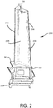
- FIG. 2 schematically depicts one example embodiment of an airfoil 200 that may be used in the compressor 102 or the turbine 112 of FIG. 1 .
- the airfoil 200 may include a leading edge 202, a trailing edge 204, a suction side 206 defined between the leading edge 202 and the trailing edge 204, and a pressure side 208 defined between the leading edge 202 and the trailing edge 204 opposite the suction side 206.
- the airfoil 200 may include a platform 210, a shank 212, a dovetail 214, and a tip shroud 216.
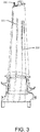
- the airfoil 200 may include a number of cooling holes 218 that exit (or break out) of the airfoil 200 in the shape of a long, narrow, ellipse 220 on the surface of the suction side 206 and/or the pressure side 208.
- the cooling holes 218 may be drilled using the Shaped Tube Electrochemical Machining (STEM) process.
- STEM Shaped Tube Electrochemical Machining
- one or more hole starter bosses 222 may be cast on the suction side 206 and/or the pressure side 208 of the airfoil 200 to enable the production of the radial cooling holes 218 that break through the airfoil surface on the suction side 206 and/or the pressure side 208.
- the cooling holes 218 may be drilled into the surface of the airfoil 200.
- the starter bosses 222 may enable a relatively step drill angle into the surface of the airfoil 200.
- the hole starter bosses 222 may be removed.
- the hole starter bosses 222 may be ground off of the surface of the suction side 206 and/or the pressure side 208 of the airfoil 200.
- the hole starter bosses 222 may include a protrusion 224 projecting from the surface of the suction side 206 and/or the pressure side 208 of the airfoil 200. In other instances, the hole starter bosses 222 may include an indentation on the surface of the suction side 206 and/or the pressure side 208 of the airfoil 200.
- the hole starter bosses 222 may include a single hole 226 or a number of holes.
- the holes 226 may act as drill guides.
- the holes 226 can be round or other producible shapes.
- the hole starter bosses 222, whether a protrusion 224 or an indentation may be cast on the surface of the suction side 206 and/or the pressure side 208 of the airfoil 200. If an indentation, the hole starter bosses 222 can also be produced by the removal of material using electrical discharge machining or other means.
- the shroud 216 at the tip of the airfoil 200 may prevent adequate access to the hole starter bosses 222.
- the shroud 216 may block the drill angle or the line-of-sight of a drill to the hole starter bosses 222.
- one or more line-of-sight access holes 228 may be drilled or cast into the shroud 216 of the airfoil 200 to provide access to the hole starter bosses 222. After the cooling holes 218 have been drilled into the surface of the airfoil 200, the line-of-sight access holes 228 may be filled in.
- the line-of-sight access holes 228 may be sealed by brazing, plugging, welding, or covered with a plate that may be brazed or welded in place.
- the cover could be on either the flowpath side or the seal side of the shroud 216 and could be recessed so as to create a smooth surface.
- Other means of closing the line-of-sight access holes 228 may also be used.
- the line-of-sight access holes 228 maybe left open.
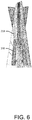
- one or more holes 230 may be drilled into the shank 212 of the airfoil 200.
- the cooling holes 218 drilled into the surface of the suction side 206 and/or the pressure side 208 of the airfoil 200 may meet with the holes 230 drilled up from the shank 212 so that the cooling holes 218 are in fluid communication with the holes 230 in the shank 212 of the airfoil 200. Accordingly, cooling air may flow from the holes 230 in the shank 212 of the airfoil 200, through the cooling holes 218, and out of the surface of the suction side 206 and/or the pressure side 208 of the airfoil 200.
Landscapes
- Engineering & Computer Science (AREA)
- Mechanical Engineering (AREA)
- General Engineering & Computer Science (AREA)
- Turbine Rotor Nozzle Sealing (AREA)
Abstract
Description
- Embodiments of the disclosure relate generally to gas turbine engines and more particularly relate to systems and methods for producing one or more cooling holes in an airfoil for a gas turbine engine.
- In some instances, buckets may be cooled with radial holes that exit (or break out) on a surface of the airfoil rather than running the full length of the airfoil and emerging at the tip. Such cooling holes may break out of the airfoil in the shape of a long, narrow, ellipse. It can be very difficult to drill holes into the airfoil at such a shallow angle.
- Some or all of the above needs and/or problems may be addressed by certain embodiments of the disclosure. According to one embodiment, there is disclosed a method for producing one or more cooling holes in an airfoil for a gas turbine engine. The method may include casting one or more hole starter bosses on a suction side, a pressure side, or both of the airfoil, drilling the one or more cooling holes into the airfoil by way of the one or more hole starter bosses, and removing the one or more hole starter bosses after drilling the one or more cooling holes into the airfoil.
- According to another embodiment, there is disclosed an airfoil for a gas turbine engine. The airfoil may include a suction side, a pressure side opposite the suction side, and one or more hole starter bosses cast on the suction side, the pressure side, or both.
- Further, according to another embodiment, there is disclosed a method for producing one or more cooling holes in an airfoil for a gas turbine engine. The method may include casting one or more hole starter bosses on a suction side, a pressure side, or both of the airfoil, drilling one or more line-of-sight access holes in a shroud of the airfoil to provide access to the one or more hole starter bosses, drilling the one or more cooling holes into the airfoil by way of the one or more hole starter bosses, and grinding the one or more hole starter bosses after drilling the one or more cooling holes into the airfoil.
- Other embodiments, aspects, and features of the disclosure will become apparent to those skilled in the art from the following detailed description, the accompanying drawings, and the appended claims.
- Reference will now be made to the accompanying drawings, which are not necessarily drawn to scale.
-
FIG. 1 schematically depicts an example view of a gas turbine engine according to an embodiment of the disclosure. -
FIG. 2 schematically depicts an example airfoil according to an embodiment of the disclosure. -
FIG. 3 schematically depicts an example airfoil according to an embodiment of the disclosure. -
FIG. 4 schematically depicts an example airfoil according to an embodiment of the disclosure. -
FIG. 5 schematically depicts an example airfoil according to an embodiment of the disclosure. -
FIG. 6 schematically depicts an example airfoil according to an embodiment of the disclosure. - Illustrative embodiments will now be described more fully hereinafter with reference to the accompanying drawings, in which some, but not all embodiments are shown. The disclosure may be embodied in many different forms and should not be construed as limited to the embodiments set forth herein. Like numbers refer to like elements throughout.
- Illustrative embodiments of the disclosure are directed to, among other things, systems and methods for producing one or more cooling holes in an airfoil for a gas turbine engine. In some instances, one or more hole starter bosses may be cast on a suction side, a pressure side, or both of the airfoil. Using the hole starter bosses as a guide, the cooling holes may be drilled into the surface of the suction side or the pressure side of the airfoil. The starter bosses may enable a relatively steep drill angle into the surface of the airfoil. After the cooling holes have been drilled into the surface of the airfoil, the hole starter bosses may be removed. For example, the hole starter bosses may be ground off of the surface of the airfoil.
- In some instances, a shroud at the tip of the airfoil may prevent adequate access to the hole starter bosses. For example, the shroud may block the drill angle or the line-of sight of a drill to the hole starter bosses. In such instances, one or more line-of-sight access holes may be drilled or cast into the shroud of the airfoil to provide access to the hole starter bosses. After the cooling holes have been drilled into the surface of the airfoil, the line-of-sight access holes may be filled in. For example, the line-of-sight access holes may be sealed by brazing, plugging, welding, or covered with a plate that may be brazed or welded in place. The cover could be on either the flowpath side or the seal side of the shroud and could be recessed so as to create a smooth surface. Other means of closing the line-of-sight access holes may also be used. In some instances, the line-of-sight access holes may be left open.
- In addition, one or more holes may be drilled into a shank of the airfoil. In this manner, the cooling holes drilled into the surface of the airfoil may meet with the holes drilled up from the shank so that the cooling holes are in fluid communication with the holes in the shank of the airfoil. Accordingly, cooling air may flow from the holes in the shank of the airfoil, through the cooling holes, and out of the surface of the suction side and/or the pressure side of the airfoil.
- In certain embodiments, the hole starter bosses may include a protrusion projecting from the surface of the suction side and/or the pressure side of the airfoil. In other instances, the hole starter bosses may include an indentation on the surface of the suction side and/or the pressure side of the airfoil. The hole starter bosses may include a single hole or a number of holes. The holes can be round or other producible shapes. The hole starter bosses, whether a protrusion or an indentation, may be cast on the surface the airfoil. If an indentation, the hole starter bosses can also be produced by the removal of material using electrical discharge machining or other means.
- Turning now to the drawings,
FIG. 1 shows a schematic view ofgas turbine engine 100 as may be used herein. Thegas turbine engine 100 may include acompressor 102. Thecompressor 102 compresses an incoming flow ofair 104. Thecompressor 102 delivers the compressed flow ofair 104 to acombustor 106. Thecombustor 106 mixes the compressed flow ofair 104 with a compressed flow offuel 108 and ignites the mixture to create a flow ofcombustion gases 110. Although only asingle combustor 106 is shown, thegas turbine engine 100 may include any number ofcombustors 106. The flow ofcombustion gases 110 is in turn delivered to adownstream turbine 112. The flow ofcombustion gases 110 drives theturbine 112 to produce mechanical work. The mechanical work produced in theturbine 112 drives thecompressor 102 via ashaft 114 and anexternal load 116, such as an electrical generator or the like. - The
gas turbine engine 100 may use natural gas, various types of syngas, and/or other types of fuels. Thegas turbine engine 100 may be anyone of a number of different gas turbine engines such as those offered by General Electric Company of Schenectady, New York and the like. Thegas turbine engine 100 may have different configurations and may use other types of components. Other types of gas turbine engines also may be used herein. Multiple gas turbine engines, other types of turbines, and other types of power generation equipment also may be used herein together. -
FIG. 2 schematically depicts one example embodiment of anairfoil 200 that may be used in thecompressor 102 or theturbine 112 ofFIG. 1 . Theairfoil 200 may include aleading edge 202, a trailingedge 204, asuction side 206 defined between theleading edge 202 and the trailingedge 204, and apressure side 208 defined between theleading edge 202 and the trailingedge 204 opposite thesuction side 206. Theairfoil 200 may include aplatform 210, ashank 212, adovetail 214, and atip shroud 216. - As depicted in
FIG. 3 , theairfoil 200 may include a number ofcooling holes 218 that exit (or break out) of theairfoil 200 in the shape of a long, narrow,ellipse 220 on the surface of thesuction side 206 and/or thepressure side 208. The cooling holes 218 may be drilled using the Shaped Tube Electrochemical Machining (STEM) process. The angle of the cooling holes 218 relative to the surface of theairfoil 200 can make it very difficult to drill the cooling holes 218 into theairfoil 200 at such a shallow angle. - As depicted in
FIG. 4 , one or morehole starter bosses 222 may be cast on thesuction side 206 and/or thepressure side 208 of theairfoil 200 to enable the production of the radial cooling holes 218 that break through the airfoil surface on thesuction side 206 and/or thepressure side 208. Using thehole starter bosses 222 as a guide, the cooling holes 218 may be drilled into the surface of theairfoil 200. In this manner, thestarter bosses 222 may enable a relatively step drill angle into the surface of theairfoil 200. After the cooling holes 218 have been drilled into the surface of theairfoil 200, thehole starter bosses 222 may be removed. For example, thehole starter bosses 222 may be ground off of the surface of thesuction side 206 and/or thepressure side 208 of theairfoil 200. - In certain embodiments, the
hole starter bosses 222 may include aprotrusion 224 projecting from the surface of thesuction side 206 and/or thepressure side 208 of theairfoil 200. In other instances, thehole starter bosses 222 may include an indentation on the surface of thesuction side 206 and/or thepressure side 208 of theairfoil 200. Thehole starter bosses 222 may include asingle hole 226 or a number of holes. Theholes 226 may act as drill guides. Theholes 226 can be round or other producible shapes. Thehole starter bosses 222, whether aprotrusion 224 or an indentation, may be cast on the surface of thesuction side 206 and/or thepressure side 208 of theairfoil 200. If an indentation, thehole starter bosses 222 can also be produced by the removal of material using electrical discharge machining or other means. - In some instances, the
shroud 216 at the tip of theairfoil 200 may prevent adequate access to thehole starter bosses 222. For example, theshroud 216 may block the drill angle or the line-of-sight of a drill to thehole starter bosses 222. In such instances, as depicted inFIG. 5 , one or more line-of-sight access holes 228 may be drilled or cast into theshroud 216 of theairfoil 200 to provide access to thehole starter bosses 222. After the cooling holes 218 have been drilled into the surface of theairfoil 200, the line-of-sight access holes 228 may be filled in. For example, the line-of-sight access holes 228 may be sealed by brazing, plugging, welding, or covered with a plate that may be brazed or welded in place. The cover could be on either the flowpath side or the seal side of theshroud 216 and could be recessed so as to create a smooth surface. Other means of closing the line-of-sight access holes 228 may also be used. In some instances, the line-of-sight access holes 228 maybe left open. - In addition, as depicted in
FIG. 6 , one ormore holes 230 may be drilled into theshank 212 of theairfoil 200. In this manner, the cooling holes 218 drilled into the surface of thesuction side 206 and/or thepressure side 208 of theairfoil 200 may meet with theholes 230 drilled up from theshank 212 so that the cooling holes 218 are in fluid communication with theholes 230 in theshank 212 of theairfoil 200. Accordingly, cooling air may flow from theholes 230 in theshank 212 of theairfoil 200, through the cooling holes 218, and out of the surface of thesuction side 206 and/or thepressure side 208 of theairfoil 200. - Although embodiments have been described in language specific to structural features and/or methodological acts, it is to be understood that the disclosure is not necessarily limited to the specific features or acts described. Rather, the specific features and acts are disclosed as illustrative forms of implementing the embodiments.
- Various aspects and embodiments of the present invention are defined by the following numbered clauses:
- 1. A method for producing one or more cooling holes in an airfoil for a gas turbine engine, the method comprising:
- casting one or more hole starter bosses on a suction side, a pressure side, or both of the airfoil;
- drilling the one or more cooling holes into the airfoil by way of the one or more hole starter bosses; and
- removing the one or more hole starter bosses after drilling the one or more cooling holes into the airfoil.
- 2. The method of clause 1, further comprising drilling one or more line-of-sight access holes in a shroud of the airfoil to provide access to the one or more hole starter bosses.
- 3. The method of any preceding clause, further comprising filling in the one or more line-of-sight access holes in the shroud of the airfoil after drilling the one or more cooling holes into the airfoil.
- 4. The method of any preceding clause, further comprising drilling one or more holes into a shank of the airfoil, wherein the one or more cooling holes are in fluid communication with the one or more holes in the shank of the airfoil.
- 5. The method of any preceding clause, wherein the one or more hole starter bosses comprise a protrusion.
- 6. The method of any preceding clause, wherein the one or more hole starter bosses comprise an indentation.
- 7. The method of any preceding clause, wherein the one or more hole starter bosses comprise a plurality of holes.
- 8. The method of any preceding clause, wherein the one or more hole starter bosses are removed by grinding.
- 9. An airfoil for a gas turbine engine, the airfoil comprising:
- a suction side;
- a pressure side opposite the suction side; and
- one or more hole starter bosses cast on the suction side, the pressure side, or both.
- 10. The airfoil of any preceding clause, wherein the one or more hole starter bosses comprise a protrusion.
- 11. The airfoil of any preceding clause, wherein the one or more hole starter bosses comprise an indentation.
- 12. The airfoil of any preceding clause, wherein the one or more hole starter bosses comprise a plurality of holes.
- 13. The airfoil of any preceding clause, further comprising one or more line-of-sight access holes in a shroud of the airfoil.
- 14. The airfoil of any preceding clause, further comprising one or more holes in a shank of the airfoil.
- 15. A method for producing one or more cooling holes in an airfoil for a gas turbine engine, the method comprising:
- casting one or more hole starter bosses on a suction side, a pressure side, or both of the airfoil;
- drilling one or more line-of-sight access holes in a shroud of the airfoil to provide access to the one or more hole starter bosses;
- drilling the one or more cooling holes into the airfoil by way of the one or more hole starter bosses; and
- grinding the one or more hole starter bosses after drilling the one or more cooling holes into the airfoil.
- 16. The method of any preceding clause, further comprising filling in the one or more line-of-sight access holes in the shroud of the airfoil after drilling the one or more cooling holes into the airfoil.
- 17. The method of any preceding clause, further comprising drilling one or more holes into a shank portion of the airfoil, wherein the one or more cooling holes are in fluid communication with the one or more holes in the shank portion of the airfoil.
- 18. The method of any preceding clause, wherein the one or more hole starter bosses comprise a protrusion.
- 19. The method of any preceding clause, wherein the one or more hole starter bosses comprise an indentation.
- 20. The method of any preceding clause, wherein the one or more hole starter bosses comprise a plurality of holes.
Claims (14)
- A method for producing one or more cooling holes (218) in an airfoil (200) for a gas turbine engine (100), the method comprising:casting one or more hole starter bosses (222) on a suction side (206), a pressure side (208), or both of the airfoil (200);drilling the one or more cooling holes (218) into the airfoil (200) by way of the one or more hole starter bosses (222); andremoving the one or more hole starter bosses (222) after drilling the one or more cooling holes (218) into the airfoil (200).
- The method of claim 1, further comprising drilling one or more line-of-sight access holes (228) in a shroud (216) of the airfoil (200) to provide access to the one or more hole starter bosses (222).
- The method of claim 2, further comprising filling in the one or more line-of-sight access holes (228) in the shroud (216) of the airfoil (200) after drilling the one or more cooling holes (218) into the airfoil (200).
- The method of claim 1, 2 or 3, further comprising drilling one or more holes (230) into a shank (212) of the airfoil (200), wherein the one or more cooling holes (218) are in fluid communication with the one or more holes (230) in the shank (218) of the airfoil (200).
- The method of any preceding claim, wherein the one or more hole starter bosses (222) comprise a protrusion (224).
- The method of any of claims 1 to 4, wherein the one or more hole starter bosses (222) comprise an indentation.
- The method of any of claims 1 to 4, wherein the one or more hole starter bosses (222) comprise a plurality of holes.
- The method of any preceding claim, wherein the one or more hole starter bosses (222) are removed by grinding.
- An airfoil (200) for a gas turbine engine (100), the airfoil (200) comprising:a suction side (206);a pressure side (208) opposite the suction side (206); and
one or more hole starter bosses (222) cast on the suction side (206), the pressure side (208), or both. - The airfoil (200) of claim 9, wherein the one or more hole starter bosses (222) comprise a protrusion (224).
- The airfoil (200) of claim 9, wherein the one or more hole starter bosses (222) comprise an indentation.
- The airfoil (200) of claim 9, wherein the one or more hole starter bosses (222) comprise a plurality of holes.
- The airfoil (200) of any of claims 9 to 12, further comprising one or more line-of-sight access holes (228) in a shroud (216) of the airfoil (200).
- The airfoil (200) of any of claims 9 to 13, further comprising one or more holes (230) in a shank (212) of the airfoil (200).
Applications Claiming Priority (1)
| Application Number | Priority Date | Filing Date | Title |
|---|---|---|---|
| US14/950,081 US10156142B2 (en) | 2015-11-24 | 2015-11-24 | Systems and methods for producing one or more cooling holes in an airfoil for a gas turbine engine |
Publications (2)
| Publication Number | Publication Date |
|---|---|
| EP3236008A1 true EP3236008A1 (en) | 2017-10-25 |
| EP3236008B1 EP3236008B1 (en) | 2022-07-27 |
Family
ID=57348548
Family Applications (1)
| Application Number | Title | Priority Date | Filing Date |
|---|---|---|---|
| EP16199471.0A Active EP3236008B1 (en) | 2015-11-24 | 2016-11-18 | Systems and methods for producing one or more cooling holes in an airfoil for a gas turbine engine |
Country Status (4)
| Country | Link |
|---|---|
| US (2) | US10156142B2 (en) |
| EP (1) | EP3236008B1 (en) |
| JP (1) | JP6845664B2 (en) |
| CN (1) | CN106914731B (en) |
Families Citing this family (4)
| Publication number | Priority date | Publication date | Assignee | Title |
|---|---|---|---|---|
| US11060407B2 (en) * | 2017-06-22 | 2021-07-13 | General Electric Company | Turbomachine rotor blade |
| US10612391B2 (en) | 2018-01-05 | 2020-04-07 | General Electric Company | Two portion cooling passage for airfoil |
| US10933481B2 (en) | 2018-01-05 | 2021-03-02 | General Electric Company | Method of forming cooling passage for turbine component with cap element |
| FR3151232A1 (en) * | 2023-07-21 | 2025-01-24 | Safran Aircraft Engines | METHOD FOR MANUFACTURING A TURBOMACHINE TURBINE BLADE |
Citations (2)
| Publication number | Priority date | Publication date | Assignee | Title |
|---|---|---|---|---|
| US5869194A (en) * | 1996-04-30 | 1999-02-09 | United Technologies Corporation | Blank for manufacturing precisely shaped parts |
| DE102014113327A1 (en) * | 2013-09-26 | 2015-03-26 | General Electric Company | Blades with shallow-angle holes and method of drilling same |
Family Cites Families (7)
| Publication number | Priority date | Publication date | Assignee | Title |
|---|---|---|---|---|
| US5117626A (en) | 1990-09-04 | 1992-06-02 | Westinghouse Electric Corp. | Apparatus for cooling rotating blades in a gas turbine |
| EP1041247B1 (en) | 1999-04-01 | 2012-08-01 | General Electric Company | Gas turbine airfoil comprising an open cooling circuit |
| DE10027842A1 (en) * | 2000-06-05 | 2001-12-20 | Alstom Power Nv | Gas turbine layout cooling system bleeds portion of film cooling air through turbine blade via inlet or outlet edge borings for direct blade wall service. |
| EP1712739A1 (en) * | 2005-04-12 | 2006-10-18 | Siemens Aktiengesellschaft | Component with film cooling hole |
| US7510376B2 (en) * | 2005-08-25 | 2009-03-31 | General Electric Company | Skewed tip hole turbine blade |
| US20070141385A1 (en) * | 2005-12-21 | 2007-06-21 | General Electric Company | Method of coating gas turbine components |
| JP6092661B2 (en) * | 2013-03-05 | 2017-03-08 | 三菱日立パワーシステムズ株式会社 | Gas turbine blade |
-
2015
- 2015-11-24 US US14/950,081 patent/US10156142B2/en active Active
-
2016
- 2016-11-17 JP JP2016223695A patent/JP6845664B2/en active Active
- 2016-11-18 EP EP16199471.0A patent/EP3236008B1/en active Active
- 2016-11-24 CN CN201611043645.9A patent/CN106914731B/en not_active Expired - Fee Related
-
2018
- 2018-11-13 US US16/188,636 patent/US20190093483A1/en not_active Abandoned
Patent Citations (2)
| Publication number | Priority date | Publication date | Assignee | Title |
|---|---|---|---|---|
| US5869194A (en) * | 1996-04-30 | 1999-02-09 | United Technologies Corporation | Blank for manufacturing precisely shaped parts |
| DE102014113327A1 (en) * | 2013-09-26 | 2015-03-26 | General Electric Company | Blades with shallow-angle holes and method of drilling same |
Also Published As
| Publication number | Publication date |
|---|---|
| JP2017106440A (en) | 2017-06-15 |
| EP3236008B1 (en) | 2022-07-27 |
| CN106914731A (en) | 2017-07-04 |
| JP6845664B2 (en) | 2021-03-24 |
| US10156142B2 (en) | 2018-12-18 |
| US20190093483A1 (en) | 2019-03-28 |
| CN106914731B (en) | 2021-11-02 |
| US20170145830A1 (en) | 2017-05-25 |
Similar Documents
| Publication | Publication Date | Title |
|---|---|---|
| EP3115147A1 (en) | Systems and methods for turbine blade repair | |
| EP2634369B1 (en) | Turbine buckets and corresponding forming method | |
| US20190093483A1 (en) | Systems and methods for producing one or more cooling holes in an airfoil for a gas turbine engine | |
| US8915713B2 (en) | Offset counterbore for airfoil cooling hole | |
| CA2647767C (en) | Method for repairing a turbine nozzle segment | |
| US10174617B2 (en) | Systems and methods for deep tip crack repair | |
| US20140360155A1 (en) | Microchannel systems and methods for cooling turbine components of a gas turbine engine | |
| EP2634370A1 (en) | Turbine bucket with a core cavity having a contoured turn | |
| US20120195742A1 (en) | Turbine bucket for use in gas turbine engines and methods for fabricating the same | |
| US9567859B2 (en) | Cooling passages for turbine buckets of a gas turbine engine | |
| EP2971545B1 (en) | Low pressure loss cooled blade | |
| EP2615253A1 (en) | Turbine Vane Seal Carrier with Slots for Cooling and Assembly | |
| EP2562359A2 (en) | Turbine nozzle vane retention system | |
| US9470098B2 (en) | Axial compressor and method for controlling stage-to-stage leakage therein | |
| EP2613012A1 (en) | Turbine nozzle cooling assembly | |
| US10822976B2 (en) | Nozzle insert rib cap | |
| US20180179899A1 (en) | Method and apparatus for brazed engine components | |
| US9745920B2 (en) | Gas turbine nozzles with embossments in airfoil cavities | |
| EP2634371B1 (en) | Turbine bucket with contoured internal rib | |
| US20150075180A1 (en) | Systems and methods for providing one or more cooling holes in a slash face of a turbine bucket | |
| US11633798B1 (en) | Braze method to modify a passage | |
| US20140271104A1 (en) | Turbine Shroud Cooling System | |
| US20140234070A1 (en) | Systems and Methods for Facilitating Onboarding of Bucket Cooling Flows |
Legal Events
| Date | Code | Title | Description |
|---|---|---|---|
| PUAI | Public reference made under article 153(3) epc to a published international application that has entered the european phase |
Free format text: ORIGINAL CODE: 0009012 |
|
| STAA | Information on the status of an ep patent application or granted ep patent |
Free format text: STATUS: THE APPLICATION HAS BEEN PUBLISHED |
|
| AK | Designated contracting states |
Kind code of ref document: A1 Designated state(s): AL AT BE BG CH CY CZ DE DK EE ES FI FR GB GR HR HU IE IS IT LI LT LU LV MC MK MT NL NO PL PT RO RS SE SI SK SM TR |
|
| AX | Request for extension of the european patent |
Extension state: BA ME |
|
| STAA | Information on the status of an ep patent application or granted ep patent |
Free format text: STATUS: REQUEST FOR EXAMINATION WAS MADE |
|
| 17P | Request for examination filed |
Effective date: 20180425 |
|
| RBV | Designated contracting states (corrected) |
Designated state(s): AL AT BE BG CH CY CZ DE DK EE ES FI FR GB GR HR HU IE IS IT LI LT LU LV MC MK MT NL NO PL PT RO RS SE SI SK SM TR |
|
| GRAP | Despatch of communication of intention to grant a patent |
Free format text: ORIGINAL CODE: EPIDOSNIGR1 |
|
| STAA | Information on the status of an ep patent application or granted ep patent |
Free format text: STATUS: GRANT OF PATENT IS INTENDED |
|
| RIC1 | Information provided on ipc code assigned before grant |
Ipc: F01D 5/00 20060101AFI20210611BHEP Ipc: F01D 5/18 20060101ALI20210611BHEP |
|
| INTG | Intention to grant announced |
Effective date: 20210709 |
|
| GRAJ | Information related to disapproval of communication of intention to grant by the applicant or resumption of examination proceedings by the epo deleted |
Free format text: ORIGINAL CODE: EPIDOSDIGR1 |
|
| STAA | Information on the status of an ep patent application or granted ep patent |
Free format text: STATUS: REQUEST FOR EXAMINATION WAS MADE |
|
| INTC | Intention to grant announced (deleted) | ||
| GRAP | Despatch of communication of intention to grant a patent |
Free format text: ORIGINAL CODE: EPIDOSNIGR1 |
|
| STAA | Information on the status of an ep patent application or granted ep patent |
Free format text: STATUS: GRANT OF PATENT IS INTENDED |
|
| INTG | Intention to grant announced |
Effective date: 20220224 |
|
| GRAS | Grant fee paid |
Free format text: ORIGINAL CODE: EPIDOSNIGR3 |
|
| GRAA | (expected) grant |
Free format text: ORIGINAL CODE: 0009210 |
|
| STAA | Information on the status of an ep patent application or granted ep patent |
Free format text: STATUS: THE PATENT HAS BEEN GRANTED |
|
| AK | Designated contracting states |
Kind code of ref document: B1 Designated state(s): AL AT BE BG CH CY CZ DE DK EE ES FI FR GB GR HR HU IE IS IT LI LT LU LV MC MK MT NL NO PL PT RO RS SE SI SK SM TR |
|
| REG | Reference to a national code |
Ref country code: CH Ref legal event code: EP |
|
| REG | Reference to a national code |
Ref country code: DE Ref legal event code: R096 Ref document number: 602016073751 Country of ref document: DE |
|
| REG | Reference to a national code |
Ref country code: AT Ref legal event code: REF Ref document number: 1507188 Country of ref document: AT Kind code of ref document: T Effective date: 20220815 |
|
| REG | Reference to a national code |
Ref country code: IE Ref legal event code: FG4D |
|
| REG | Reference to a national code |
Ref country code: LT Ref legal event code: MG9D |
|
| REG | Reference to a national code |
Ref country code: NL Ref legal event code: MP Effective date: 20220727 |
|
| PG25 | Lapsed in a contracting state [announced via postgrant information from national office to epo] |
Ref country code: SE Free format text: LAPSE BECAUSE OF FAILURE TO SUBMIT A TRANSLATION OF THE DESCRIPTION OR TO PAY THE FEE WITHIN THE PRESCRIBED TIME-LIMIT Effective date: 20220727 Ref country code: RS Free format text: LAPSE BECAUSE OF FAILURE TO SUBMIT A TRANSLATION OF THE DESCRIPTION OR TO PAY THE FEE WITHIN THE PRESCRIBED TIME-LIMIT Effective date: 20220727 Ref country code: PT Free format text: LAPSE BECAUSE OF FAILURE TO SUBMIT A TRANSLATION OF THE DESCRIPTION OR TO PAY THE FEE WITHIN THE PRESCRIBED TIME-LIMIT Effective date: 20221128 Ref country code: NO Free format text: LAPSE BECAUSE OF FAILURE TO SUBMIT A TRANSLATION OF THE DESCRIPTION OR TO PAY THE FEE WITHIN THE PRESCRIBED TIME-LIMIT Effective date: 20221027 Ref country code: NL Free format text: LAPSE BECAUSE OF FAILURE TO SUBMIT A TRANSLATION OF THE DESCRIPTION OR TO PAY THE FEE WITHIN THE PRESCRIBED TIME-LIMIT Effective date: 20220727 Ref country code: LV Free format text: LAPSE BECAUSE OF FAILURE TO SUBMIT A TRANSLATION OF THE DESCRIPTION OR TO PAY THE FEE WITHIN THE PRESCRIBED TIME-LIMIT Effective date: 20220727 Ref country code: LT Free format text: LAPSE BECAUSE OF FAILURE TO SUBMIT A TRANSLATION OF THE DESCRIPTION OR TO PAY THE FEE WITHIN THE PRESCRIBED TIME-LIMIT Effective date: 20220727 Ref country code: FI Free format text: LAPSE BECAUSE OF FAILURE TO SUBMIT A TRANSLATION OF THE DESCRIPTION OR TO PAY THE FEE WITHIN THE PRESCRIBED TIME-LIMIT Effective date: 20220727 Ref country code: ES Free format text: LAPSE BECAUSE OF FAILURE TO SUBMIT A TRANSLATION OF THE DESCRIPTION OR TO PAY THE FEE WITHIN THE PRESCRIBED TIME-LIMIT Effective date: 20220727 |
|
| PGFP | Annual fee paid to national office [announced via postgrant information from national office to epo] |
Ref country code: GB Payment date: 20221021 Year of fee payment: 7 |
|
| REG | Reference to a national code |
Ref country code: AT Ref legal event code: MK05 Ref document number: 1507188 Country of ref document: AT Kind code of ref document: T Effective date: 20220727 |
|
| PG25 | Lapsed in a contracting state [announced via postgrant information from national office to epo] |
Ref country code: PL Free format text: LAPSE BECAUSE OF FAILURE TO SUBMIT A TRANSLATION OF THE DESCRIPTION OR TO PAY THE FEE WITHIN THE PRESCRIBED TIME-LIMIT Effective date: 20220727 Ref country code: IS Free format text: LAPSE BECAUSE OF FAILURE TO SUBMIT A TRANSLATION OF THE DESCRIPTION OR TO PAY THE FEE WITHIN THE PRESCRIBED TIME-LIMIT Effective date: 20221127 Ref country code: HR Free format text: LAPSE BECAUSE OF FAILURE TO SUBMIT A TRANSLATION OF THE DESCRIPTION OR TO PAY THE FEE WITHIN THE PRESCRIBED TIME-LIMIT Effective date: 20220727 Ref country code: GR Free format text: LAPSE BECAUSE OF FAILURE TO SUBMIT A TRANSLATION OF THE DESCRIPTION OR TO PAY THE FEE WITHIN THE PRESCRIBED TIME-LIMIT Effective date: 20221028 |
|
| PG25 | Lapsed in a contracting state [announced via postgrant information from national office to epo] |
Ref country code: SM Free format text: LAPSE BECAUSE OF FAILURE TO SUBMIT A TRANSLATION OF THE DESCRIPTION OR TO PAY THE FEE WITHIN THE PRESCRIBED TIME-LIMIT Effective date: 20220727 Ref country code: RO Free format text: LAPSE BECAUSE OF FAILURE TO SUBMIT A TRANSLATION OF THE DESCRIPTION OR TO PAY THE FEE WITHIN THE PRESCRIBED TIME-LIMIT Effective date: 20220727 Ref country code: DK Free format text: LAPSE BECAUSE OF FAILURE TO SUBMIT A TRANSLATION OF THE DESCRIPTION OR TO PAY THE FEE WITHIN THE PRESCRIBED TIME-LIMIT Effective date: 20220727 Ref country code: CZ Free format text: LAPSE BECAUSE OF FAILURE TO SUBMIT A TRANSLATION OF THE DESCRIPTION OR TO PAY THE FEE WITHIN THE PRESCRIBED TIME-LIMIT Effective date: 20220727 Ref country code: AT Free format text: LAPSE BECAUSE OF FAILURE TO SUBMIT A TRANSLATION OF THE DESCRIPTION OR TO PAY THE FEE WITHIN THE PRESCRIBED TIME-LIMIT Effective date: 20220727 |
|
| REG | Reference to a national code |
Ref country code: DE Ref legal event code: R097 Ref document number: 602016073751 Country of ref document: DE |
|
| PG25 | Lapsed in a contracting state [announced via postgrant information from national office to epo] |
Ref country code: SK Free format text: LAPSE BECAUSE OF FAILURE TO SUBMIT A TRANSLATION OF THE DESCRIPTION OR TO PAY THE FEE WITHIN THE PRESCRIBED TIME-LIMIT Effective date: 20220727 Ref country code: EE Free format text: LAPSE BECAUSE OF FAILURE TO SUBMIT A TRANSLATION OF THE DESCRIPTION OR TO PAY THE FEE WITHIN THE PRESCRIBED TIME-LIMIT Effective date: 20220727 |
|
| PLBE | No opposition filed within time limit |
Free format text: ORIGINAL CODE: 0009261 |
|
| STAA | Information on the status of an ep patent application or granted ep patent |
Free format text: STATUS: NO OPPOSITION FILED WITHIN TIME LIMIT |
|
| PG25 | Lapsed in a contracting state [announced via postgrant information from national office to epo] |
Ref country code: MC Free format text: LAPSE BECAUSE OF FAILURE TO SUBMIT A TRANSLATION OF THE DESCRIPTION OR TO PAY THE FEE WITHIN THE PRESCRIBED TIME-LIMIT Effective date: 20220727 Ref country code: AL Free format text: LAPSE BECAUSE OF FAILURE TO SUBMIT A TRANSLATION OF THE DESCRIPTION OR TO PAY THE FEE WITHIN THE PRESCRIBED TIME-LIMIT Effective date: 20220727 |
|
| REG | Reference to a national code |
Ref country code: CH Ref legal event code: PL |
|
| 26N | No opposition filed |
Effective date: 20230502 |
|
| REG | Reference to a national code |
Ref country code: BE Ref legal event code: MM Effective date: 20221130 |
|
| PG25 | Lapsed in a contracting state [announced via postgrant information from national office to epo] |
Ref country code: LI Free format text: LAPSE BECAUSE OF NON-PAYMENT OF DUE FEES Effective date: 20221130 Ref country code: CH Free format text: LAPSE BECAUSE OF NON-PAYMENT OF DUE FEES Effective date: 20221130 |
|
| PG25 | Lapsed in a contracting state [announced via postgrant information from national office to epo] |
Ref country code: SI Free format text: LAPSE BECAUSE OF FAILURE TO SUBMIT A TRANSLATION OF THE DESCRIPTION OR TO PAY THE FEE WITHIN THE PRESCRIBED TIME-LIMIT Effective date: 20220727 Ref country code: LU Free format text: LAPSE BECAUSE OF NON-PAYMENT OF DUE FEES Effective date: 20221118 |
|
| PG25 | Lapsed in a contracting state [announced via postgrant information from national office to epo] |
Ref country code: IE Free format text: LAPSE BECAUSE OF NON-PAYMENT OF DUE FEES Effective date: 20221118 |
|
| REG | Reference to a national code |
Ref country code: DE Ref legal event code: R081 Ref document number: 602016073751 Country of ref document: DE Owner name: GENERAL ELECTRIC TECHNOLOGY GMBH, CH Free format text: FORMER OWNER: GENERAL ELECTRIC COMPANY, SCHENECTADY, NY, US |
|
| PG25 | Lapsed in a contracting state [announced via postgrant information from national office to epo] |
Ref country code: FR Free format text: LAPSE BECAUSE OF NON-PAYMENT OF DUE FEES Effective date: 20221130 Ref country code: BE Free format text: LAPSE BECAUSE OF NON-PAYMENT OF DUE FEES Effective date: 20221130 |
|
| REG | Reference to a national code |
Ref country code: GB Ref legal event code: 732E Free format text: REGISTERED BETWEEN 20240222 AND 20240228 |
|
| PG25 | Lapsed in a contracting state [announced via postgrant information from national office to epo] |
Ref country code: HU Free format text: LAPSE BECAUSE OF FAILURE TO SUBMIT A TRANSLATION OF THE DESCRIPTION OR TO PAY THE FEE WITHIN THE PRESCRIBED TIME-LIMIT; INVALID AB INITIO Effective date: 20161118 |
|
| PG25 | Lapsed in a contracting state [announced via postgrant information from national office to epo] |
Ref country code: CY Free format text: LAPSE BECAUSE OF FAILURE TO SUBMIT A TRANSLATION OF THE DESCRIPTION OR TO PAY THE FEE WITHIN THE PRESCRIBED TIME-LIMIT Effective date: 20220727 |
|
| PG25 | Lapsed in a contracting state [announced via postgrant information from national office to epo] |
Ref country code: MK Free format text: LAPSE BECAUSE OF FAILURE TO SUBMIT A TRANSLATION OF THE DESCRIPTION OR TO PAY THE FEE WITHIN THE PRESCRIBED TIME-LIMIT Effective date: 20220727 Ref country code: IT Free format text: LAPSE BECAUSE OF FAILURE TO SUBMIT A TRANSLATION OF THE DESCRIPTION OR TO PAY THE FEE WITHIN THE PRESCRIBED TIME-LIMIT Effective date: 20220727 |
|
| GBPC | Gb: european patent ceased through non-payment of renewal fee |
Effective date: 20231118 |
|
| PG25 | Lapsed in a contracting state [announced via postgrant information from national office to epo] |
Ref country code: BG Free format text: LAPSE BECAUSE OF FAILURE TO SUBMIT A TRANSLATION OF THE DESCRIPTION OR TO PAY THE FEE WITHIN THE PRESCRIBED TIME-LIMIT Effective date: 20220727 |
|
| PG25 | Lapsed in a contracting state [announced via postgrant information from national office to epo] |
Ref country code: MT Free format text: LAPSE BECAUSE OF FAILURE TO SUBMIT A TRANSLATION OF THE DESCRIPTION OR TO PAY THE FEE WITHIN THE PRESCRIBED TIME-LIMIT Effective date: 20220727 |
|
| PG25 | Lapsed in a contracting state [announced via postgrant information from national office to epo] |
Ref country code: GB Free format text: LAPSE BECAUSE OF NON-PAYMENT OF DUE FEES Effective date: 20231118 |
|
| PG25 | Lapsed in a contracting state [announced via postgrant information from national office to epo] |
Ref country code: GB Free format text: LAPSE BECAUSE OF NON-PAYMENT OF DUE FEES Effective date: 20231118 |
|
| PG25 | Lapsed in a contracting state [announced via postgrant information from national office to epo] |
Ref country code: TR Free format text: LAPSE BECAUSE OF FAILURE TO SUBMIT A TRANSLATION OF THE DESCRIPTION OR TO PAY THE FEE WITHIN THE PRESCRIBED TIME-LIMIT Effective date: 20220727 |
|
| PGFP | Annual fee paid to national office [announced via postgrant information from national office to epo] |
Ref country code: DE Payment date: 20251022 Year of fee payment: 10 |