EP3235943A1 - Laundry drying device with heat pump and its drive - Google Patents
Laundry drying device with heat pump and its drive Download PDFInfo
- Publication number
- EP3235943A1 EP3235943A1 EP17163068.4A EP17163068A EP3235943A1 EP 3235943 A1 EP3235943 A1 EP 3235943A1 EP 17163068 A EP17163068 A EP 17163068A EP 3235943 A1 EP3235943 A1 EP 3235943A1
- Authority
- EP
- European Patent Office
- Prior art keywords
- floor assembly
- drying apparatus
- bolt
- laundry drying
- grommets
- Prior art date
- Legal status (The legal status is an assumption and is not a legal conclusion. Google has not performed a legal analysis and makes no representation as to the accuracy of the status listed.)
- Granted
Links
- 238000001035 drying Methods 0.000 title claims abstract description 23
- 230000000284 resting effect Effects 0.000 claims abstract description 6
- 239000002184 metal Substances 0.000 claims description 32
- 239000004033 plastic Substances 0.000 claims description 20
- 229920003023 plastic Polymers 0.000 claims description 20
- 239000000463 material Substances 0.000 claims description 7
- 238000007373 indentation Methods 0.000 claims description 2
- 229910000831 Steel Inorganic materials 0.000 claims 1
- 239000010959 steel Substances 0.000 claims 1
- 239000000853 adhesive Substances 0.000 description 4
- 230000001070 adhesive effect Effects 0.000 description 4
- 238000010521 absorption reaction Methods 0.000 description 2
- 238000013016 damping Methods 0.000 description 2
- 239000011152 fibreglass Substances 0.000 description 2
- 239000006260 foam Substances 0.000 description 2
- 238000009413 insulation Methods 0.000 description 2
- 238000004519 manufacturing process Methods 0.000 description 2
- 230000002787 reinforcement Effects 0.000 description 2
- 239000004793 Polystyrene Substances 0.000 description 1
- 229920006328 Styrofoam Polymers 0.000 description 1
- 238000004026 adhesive bonding Methods 0.000 description 1
- 239000011324 bead Substances 0.000 description 1
- 150000001875 compounds Chemical class 0.000 description 1
- 238000010276 construction Methods 0.000 description 1
- 230000001419 dependent effect Effects 0.000 description 1
- 230000000694 effects Effects 0.000 description 1
- 238000003780 insertion Methods 0.000 description 1
- 230000037431 insertion Effects 0.000 description 1
- 238000000034 method Methods 0.000 description 1
- 238000005457 optimization Methods 0.000 description 1
- 229920001296 polysiloxane Polymers 0.000 description 1
- 229920002223 polystyrene Polymers 0.000 description 1
- 238000004382 potting Methods 0.000 description 1
- 238000003825 pressing Methods 0.000 description 1
- 230000003134 recirculating effect Effects 0.000 description 1
- 238000010079 rubber tapping Methods 0.000 description 1
- 239000003351 stiffener Substances 0.000 description 1
- 238000003860 storage Methods 0.000 description 1
- 239000008261 styrofoam Substances 0.000 description 1
- 230000007704 transition Effects 0.000 description 1
- 238000002604 ultrasonography Methods 0.000 description 1
- 238000005406 washing Methods 0.000 description 1
- 238000003466 welding Methods 0.000 description 1
Images


Classifications
-
- D—TEXTILES; PAPER
- D06—TREATMENT OF TEXTILES OR THE LIKE; LAUNDERING; FLEXIBLE MATERIALS NOT OTHERWISE PROVIDED FOR
- D06F—LAUNDERING, DRYING, IRONING, PRESSING OR FOLDING TEXTILE ARTICLES
- D06F58/00—Domestic laundry dryers
- D06F58/20—General details of domestic laundry dryers
-
- F—MECHANICAL ENGINEERING; LIGHTING; HEATING; WEAPONS; BLASTING
- F16—ENGINEERING ELEMENTS AND UNITS; GENERAL MEASURES FOR PRODUCING AND MAINTAINING EFFECTIVE FUNCTIONING OF MACHINES OR INSTALLATIONS; THERMAL INSULATION IN GENERAL
- F16B—DEVICES FOR FASTENING OR SECURING CONSTRUCTIONAL ELEMENTS OR MACHINE PARTS TOGETHER, e.g. NAILS, BOLTS, CIRCLIPS, CLAMPS, CLIPS OR WEDGES; JOINTS OR JOINTING
- F16B5/00—Joining sheets or plates, e.g. panels, to one another or to strips or bars parallel to them
- F16B5/02—Joining sheets or plates, e.g. panels, to one another or to strips or bars parallel to them by means of fastening members using screw-thread
- F16B5/0241—Joining sheets or plates, e.g. panels, to one another or to strips or bars parallel to them by means of fastening members using screw-thread with the possibility for the connection to absorb deformation, e.g. thermal or vibrational
-
- D—TEXTILES; PAPER
- D06—TREATMENT OF TEXTILES OR THE LIKE; LAUNDERING; FLEXIBLE MATERIALS NOT OTHERWISE PROVIDED FOR
- D06F—LAUNDERING, DRYING, IRONING, PRESSING OR FOLDING TEXTILE ARTICLES
- D06F37/00—Details specific to washing machines covered by groups D06F21/00 - D06F25/00
- D06F37/20—Mountings, e.g. resilient mountings, for the rotary receptacle, motor, tub or casing; Preventing or damping vibrations
-
- D—TEXTILES; PAPER
- D06—TREATMENT OF TEXTILES OR THE LIKE; LAUNDERING; FLEXIBLE MATERIALS NOT OTHERWISE PROVIDED FOR
- D06F—LAUNDERING, DRYING, IRONING, PRESSING OR FOLDING TEXTILE ARTICLES
- D06F58/00—Domestic laundry dryers
- D06F58/20—General details of domestic laundry dryers
- D06F58/206—Heat pump arrangements
-
- F—MECHANICAL ENGINEERING; LIGHTING; HEATING; WEAPONS; BLASTING
- F16—ENGINEERING ELEMENTS AND UNITS; GENERAL MEASURES FOR PRODUCING AND MAINTAINING EFFECTIVE FUNCTIONING OF MACHINES OR INSTALLATIONS; THERMAL INSULATION IN GENERAL
- F16B—DEVICES FOR FASTENING OR SECURING CONSTRUCTIONAL ELEMENTS OR MACHINE PARTS TOGETHER, e.g. NAILS, BOLTS, CIRCLIPS, CLAMPS, CLIPS OR WEDGES; JOINTS OR JOINTING
- F16B23/00—Specially shaped nuts or heads of bolts or screws for rotations by a tool
- F16B23/0007—Specially shaped nuts or heads of bolts or screws for rotations by a tool characterised by the shape of the recess or the protrusion engaging the tool
- F16B23/0023—Specially shaped nuts or heads of bolts or screws for rotations by a tool characterised by the shape of the recess or the protrusion engaging the tool substantially cross-shaped
-
- F—MECHANICAL ENGINEERING; LIGHTING; HEATING; WEAPONS; BLASTING
- F16—ENGINEERING ELEMENTS AND UNITS; GENERAL MEASURES FOR PRODUCING AND MAINTAINING EFFECTIVE FUNCTIONING OF MACHINES OR INSTALLATIONS; THERMAL INSULATION IN GENERAL
- F16B—DEVICES FOR FASTENING OR SECURING CONSTRUCTIONAL ELEMENTS OR MACHINE PARTS TOGETHER, e.g. NAILS, BOLTS, CIRCLIPS, CLAMPS, CLIPS OR WEDGES; JOINTS OR JOINTING
- F16B23/00—Specially shaped nuts or heads of bolts or screws for rotations by a tool
- F16B23/0007—Specially shaped nuts or heads of bolts or screws for rotations by a tool characterised by the shape of the recess or the protrusion engaging the tool
- F16B23/003—Specially shaped nuts or heads of bolts or screws for rotations by a tool characterised by the shape of the recess or the protrusion engaging the tool star-shaped or multi-lobular, e.g. Torx-type, twelve-point star
-
- F—MECHANICAL ENGINEERING; LIGHTING; HEATING; WEAPONS; BLASTING
- F16—ENGINEERING ELEMENTS AND UNITS; GENERAL MEASURES FOR PRODUCING AND MAINTAINING EFFECTIVE FUNCTIONING OF MACHINES OR INSTALLATIONS; THERMAL INSULATION IN GENERAL
- F16B—DEVICES FOR FASTENING OR SECURING CONSTRUCTIONAL ELEMENTS OR MACHINE PARTS TOGETHER, e.g. NAILS, BOLTS, CIRCLIPS, CLAMPS, CLIPS OR WEDGES; JOINTS OR JOINTING
- F16B23/00—Specially shaped nuts or heads of bolts or screws for rotations by a tool
- F16B23/0007—Specially shaped nuts or heads of bolts or screws for rotations by a tool characterised by the shape of the recess or the protrusion engaging the tool
- F16B23/0038—Specially shaped nuts or heads of bolts or screws for rotations by a tool characterised by the shape of the recess or the protrusion engaging the tool substantially prismatic with up to six edges, e.g. triangular, square, pentagonal, Allen-type cross-sections
-
- F—MECHANICAL ENGINEERING; LIGHTING; HEATING; WEAPONS; BLASTING
- F16—ENGINEERING ELEMENTS AND UNITS; GENERAL MEASURES FOR PRODUCING AND MAINTAINING EFFECTIVE FUNCTIONING OF MACHINES OR INSTALLATIONS; THERMAL INSULATION IN GENERAL
- F16B—DEVICES FOR FASTENING OR SECURING CONSTRUCTIONAL ELEMENTS OR MACHINE PARTS TOGETHER, e.g. NAILS, BOLTS, CIRCLIPS, CLAMPS, CLIPS OR WEDGES; JOINTS OR JOINTING
- F16B25/00—Screws that cut thread in the body into which they are screwed, e.g. wood screws
- F16B25/001—Screws that cut thread in the body into which they are screwed, e.g. wood screws characterised by the material of the body into which the screw is screwed
- F16B25/0015—Screws that cut thread in the body into which they are screwed, e.g. wood screws characterised by the material of the body into which the screw is screwed the material being a soft organic material, e.g. wood or plastic
-
- F—MECHANICAL ENGINEERING; LIGHTING; HEATING; WEAPONS; BLASTING
- F16—ENGINEERING ELEMENTS AND UNITS; GENERAL MEASURES FOR PRODUCING AND MAINTAINING EFFECTIVE FUNCTIONING OF MACHINES OR INSTALLATIONS; THERMAL INSULATION IN GENERAL
- F16B—DEVICES FOR FASTENING OR SECURING CONSTRUCTIONAL ELEMENTS OR MACHINE PARTS TOGETHER, e.g. NAILS, BOLTS, CIRCLIPS, CLAMPS, CLIPS OR WEDGES; JOINTS OR JOINTING
- F16B25/00—Screws that cut thread in the body into which they are screwed, e.g. wood screws
- F16B25/0036—Screws that cut thread in the body into which they are screwed, e.g. wood screws characterised by geometric details of the screw
- F16B25/0042—Screws that cut thread in the body into which they are screwed, e.g. wood screws characterised by geometric details of the screw characterised by the geometry of the thread, the thread being a ridge wrapped around the shaft of the screw
- F16B25/0057—Screws that cut thread in the body into which they are screwed, e.g. wood screws characterised by geometric details of the screw characterised by the geometry of the thread, the thread being a ridge wrapped around the shaft of the screw the screw having distinct axial zones, e.g. multiple axial thread sections with different pitch or thread cross-sections
- F16B25/0063—Screws that cut thread in the body into which they are screwed, e.g. wood screws characterised by geometric details of the screw characterised by the geometry of the thread, the thread being a ridge wrapped around the shaft of the screw the screw having distinct axial zones, e.g. multiple axial thread sections with different pitch or thread cross-sections with a non-threaded portion on the shaft of the screw
-
- F—MECHANICAL ENGINEERING; LIGHTING; HEATING; WEAPONS; BLASTING
- F16—ENGINEERING ELEMENTS AND UNITS; GENERAL MEASURES FOR PRODUCING AND MAINTAINING EFFECTIVE FUNCTIONING OF MACHINES OR INSTALLATIONS; THERMAL INSULATION IN GENERAL
- F16B—DEVICES FOR FASTENING OR SECURING CONSTRUCTIONAL ELEMENTS OR MACHINE PARTS TOGETHER, e.g. NAILS, BOLTS, CIRCLIPS, CLAMPS, CLIPS OR WEDGES; JOINTS OR JOINTING
- F16B43/00—Washers or equivalent devices; Other devices for supporting bolt-heads or nuts
Definitions
- the invention relates to a laundry drying apparatus, comprising a bottom group and a drive of a heat pump, which drive is connected to a plurality of elastic Grommets and Grommets are attached by means of bolts which are passed through the grommets to the floor assembly.
- the invention is particularly advantageously applicable to tumble dryer and washer-dryer with a compressor as a drive.
- Figure 9 shows an oblique view of a section of a clothes dryer 101 with a bottom assembly 102 made of plastic, which carries a drive of a heat pump in the form of a compressor 103.
- the compressor 103 generates vibrations, which may sometimes cause noise in the tumble dryer 101.
- the compressor 103 is on three rubber elements, the so-called Grommets 104.
- first three bolts 105 are pressed through corresponding holes in a metal frame or in a metal plate 106. This metal plate 106 is then screwed onto the floor assembly 102. In the immediate vicinity of the bolt 105, the metal plate 106 forms a flange.
- the compressor 103 at the three feet of each Grommet 104 is placed over the bolt 105.
- the Grommets 104 are exclusively in contact with the metal plate 106, namely by resting on the plate and pressing on the flange.
- a washer 107 with a self-locking nut 108 is fastened to a separate shoulder of the bolts 105. Due to the weight of the compressor 103, the grommets 104 are compressed during operation so far that a gap occurs between the washer 107 and a respective grommet 104.
- the washer 107 prevents the compressor 103 from lifting off the metal plate 106 at both turning on and off and transportation.
- EP 2 559 804 A1 discloses a domestic appliance, in particular tumble dryer or washer-dryer, comprising a drive unit for a heat pump cycle, in which the drive unit by means of a mechanical fastening device with a connected to the other component of the household appliance, wherein the mechanical fastening device comprises a first, fastened to the drive unit fastener, a second, attached to the other component of the household appliance fastener and an elastic Grommet that connects the fasteners together.
- a clothes drying apparatus comprising a bottom group and a drive of a heat pump, which drive is connected to a plurality of elastic Grommets and the Grommets are attached by means of bolts which are passed through the Grommets to the floor assembly, the Grommets directly on the Floor group rest.
- the laundry drying apparatus is in particular a tumble dryer or a combined washing / drying appliance ("washer-dryer").
- the laundry drying apparatus is in particular a household appliance.
- the laundry drying device is in particular a recirculating air dryer with a circulating process air cycle.
- a floor assembly Under a floor assembly is in particular a storage or support component for fixing a plurality of functional components of the laundry drying apparatus such as a drive, at least one heat exchanger, a condensate tray, etc. understood.
- the bottom group is arranged on the bottom side in the laundry drying device. In particular, it has a base made of plastic and may also consist entirely of plastic.
- the drive of the heat pump may be a compressor in the case of a compressor heat pump.
- a Stirling heat pump or a Vuilleumier heat pump can be used with appropriate drives.
- the drive is connected indirectly via the elastic Grommets with the bottom group or lies indirectly on the elastic grommets on the floor assembly.
- a Grommet can be understood in particular a ring or a spout.
- the grommets can be made of rubber.
- the bolt can be a socket pin or a bolt (screw).
- the bolt can rest over a washer on the Grommet, in particular press on the Grommet.
- the Grommet can be moved against the bottom group serving to repelers. This can compress the Grommet, but it does not need it.
- the drive can, for example, be releasably or non-releasably locked into the grommets, clamped and / or mounted on the grommets.
- the Grommet can have lateral receiving recesses, eg ringnutartige recesses.
- the drive can eg have been introduced in a return of each Grommets.
- the drive can be pressed by the bolts on the respective Grommets.
- the respective bolts are inserted into at least inside sleeve-shaped attachment areas of the bottom group of plastic or metal.
- the attachment areas allow a long contact surface with the bolt and a reliable recording of the bolt.
- the bolts have an external thread for screwing on a, in particular self-locking, nut.
- the bolt may be a e.g. have annular shoulder for placing a washer. The nut and washer can be used to secure the grommet against lifting off the underbody and / or to push the grommet against the underbody.
- the sleeve-shaped attachment portions may be at least partially plugged into the through hole of the Grommet to effect a precise and reliable positioning of the Grommet. This can also be seen that the Grommet can be plugged onto a portion of the sleeve-shaped mounting portion.
- the sleeve-shaped mounting portions of the floor assembly can be made entirely of plastic, which reduces manufacturing costs.
- the attachment areas are formed at least on the inside as metal sleeves, which are embedded in plastic of the bottom group.
- the metal sleeves may have internal screw thread or internal thread. To prevent rotation of the metal sleeves, they may be provided on the outside with projections or recesses (eg ribs or indentations) and / or not rotationally symmetrical.
- the metal sleeves can be encapsulated in the manufacture of the bottom group with the plastic of the base body of the bottom group.
- a sleeve in particular metal sleeve, is slipped over a shaft of the bolt, which sleeve rests on the fastening area, in particular an edge thereof.
- a rigidity of the connection between the drive and the floor assembly can be increased in a particularly reliable manner.
- the sleeve rests on its other edge on a washer, which, e.g. is pressed by the bolt in the direction of the floor assembly.
- a washer located between the bolt and the Grommet rests directly on the mounting area of the floor assembly.
- the attachment area may be pulled forward to the washer.
- the attachment area may extend through the entire through hole of the grommet.
- the bolt may rest directly on the mounting area, e.g. with a screw head or a flange.
- the bolts are bolts that are screwed into the mounting areas.
- the bolt may have an external thread, e.g. at its front end portion.
- the respective bolts are bolt bolts having a front portion provided with a first external thread and a rear portion provided with a second externally threaded portion are screwed with their front portion into the mounting portions and with their rear portion thereof Fix Grommet.
- This embodiment provides the advantage that a simple attachment to the floor assembly and also a fixation of Grommets can be achieved by respective Verschraubungsvor réelle.
- the attachment to the floor assembly and the fixation of Grommets are independently adjustable, eg their screwing force.
- Another advantage is that the attachment region of the floor assembly in which the bolt is screwed with its first external thread, either as a through hole or as a non-continuous blind hole is performed.
- the first external thread can engage in an internal thread of the fastening region or be formed as a self-tapping thread.
- the first external thread can be screwed directly into the material of the floor assembly or, as also described below, or screwed into a introduced into the bottom group (continuous or non-going) sleeve.
- the first external thread and the second external thread may be the same or different.
- the first external thread and the second external thread may be a right-hand thread and a left-hand thread, have a different diameter (e.g., the second external thread may have a smaller diameter), and / or have a different pitch, etc.
- the threaded portion is for engagement by a bolting means for rotating the bolt, e.g. through a wrench.
- the screwed-in section may, in particular, have an angular outer contour, e.g. a hexagonal outer contour, etc.
- the front portion of the screwed portion is separated by a - particular ring-like or disc-like - screw flange.
- the bolt can be particularly reliable and precisely supported on the floor assembly. It is an advantageous embodiment for preventing a rotation or rotation of the screwed into the floor assembly and resting on the floor group bolt that notches are present on an underside facing the front portion of the screw.
- the screw-in portion provides a shoulder toward the rear portion.
- This provides the advantage that a washer can be placed on this paragraph.
- the washer can be secured, for example, with a self-locking nut to prevent lifting of the compressor.
- the respective bolts are locking pins, which are inserted through the bottom group, in particular an associated mounting portion, and the Grommet. This allows a screwing for insertion in the floor group can be avoided.
- the locking pins can rest on the one hand on the floor assembly and on the other hand on the Grommet or an intermediate washer, in particular be secured.
- the locking pin can in particular with the component in which it has been introduced first, stop. If the pin is first inserted from below through the floor assembly and then through the grommet, the floor assembly acts as a stop. If the locking pin is first inserted through the Grommet or a washer from above, the Grommet or washer acts as a stop.
- the front side of the socket pin may have an external thread for screwing a nut.
- the bolts have laterally protruding projections or flanges for resting on the floor assembly or on a washer. So a particularly secure and reliable connection can be achieved.
- the bottom group has a cup-shaped structure and / or a rib-like structure for receiving forces introduced by the bolts.
- Such structures are very stable at low weight.
- their rigidity can be easily adjusted, e.g. by varying their size, wall thickness, etc.
- the bottom group in particular its shell-shaped structure and / or a rib-like structure, at least partially filled. This allows even more versatile implementation of stiffness, damping and noise optimization.
- the filling can e.g. by gluing, welding, etc. of plastic material (also of a material other than that of the floor assembly, for example of fiberglass reinforced plastic).
- plastic material also of a material other than that of the floor assembly, for example of fiberglass reinforced plastic.
- adhesives e.g. vibration-absorbing adhesives suitable.
- the floor assembly can be filled with concrete and possibly reinforcement.
- the floor group with foam, polystyrene, silicone, plastic, tar, etc. are filled.
- 1A shows a sectional side view of a clothes dryer 1 in the region of attachment of a compressor 103 to a floor assembly 2 made of plastic.
- 1B shows a bolt 3 for attaching the compressor 103 to the floor assembly 2.
- the bolt 3 passes through a Grommet 104.
- the Grommet 104 rests directly on the floor assembly 2.
- the compressor 103 is positively inserted into a circumferential recess 109 of the Grommets 104.
- the bolt 3 has a male thread 4a at a front portion 4, and thus is formed there as a screw.
- the bolt 3 is screwed from above or from inside into a tubular or sleeve-like fastening region 5 of the floor assembly 2.
- the bolt 3 has a laterally projecting shoulder or screw flange 6, which is supported on an upper-side edge of the mounting portion 5.
- the attachment region 5 can optionally protrude into a through hole 110 of the grommet 104, through which the bolt 3 extends, and then also serves to secure the grommet 104 more securely.
- a screw portion 7 in the form of an external hexagon (as shown), a hexagon socket, an inner torx or a Phillips, etc. may be provided in a head of the bolt 3.
- FIG. 8 Another paragraph 8 serves to hang up a washer 107.
- the washer 107 may be secured with a self-locking nut 108 to prevent lifting of the compressor 103, e.g. analogous to the tumble dryer 101.
- the nut 108 can be screwed onto a further external thread 9a present on a rear region 9 of the bolt 3.
- the Grommet 104 is thus held or fixed between the bottom group 2 and the washer 107.
- notches may be provided on a threaded side underside of the screw flange 6, on which the edge of the screw-in portion 5 rests.
- the front section 4 is thus separated from the rear section 9 by the screw-in section 7 and separated from the screw-in section 7 by the screw flange 6.
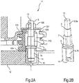
- 2A shows a sectional side view of a clothes dryer 11 in the region of attachment of a compressor 103 to a floor assembly 12th
- 2B 1 shows a bolt 13 for fastening the compressor 103 to the floor assembly 12 with a metal bushing 14 of the floor assembly 12.
- the bolt 13 also extends through the through hole 110 of the grommet 104 here.
- the Grommet 104 rests directly on a plastic region of the floor assembly 12.
- the metal bush 14 may optionally protrude into the through hole 110 of the grommet 104.
- the metal bushing 14 then also serves for the safer positioning of the grommet 104.
- the metal bushing 14 is equipped with an internal thread and embedded in a mounting portion 15 in the existing plastic bottom group 12, for example, injected, pressed, embedded with ultrasound and / or welded, etc.
- the bolt 13 is screwed into the metal bushing 14.
- the bolt 13 differs if necessary, only by the nature of its external thread 16 of the bolt 3.
- they can on the outside of the circular cylindrical shape reject, for example, by being not rotationally symmetrical, has longitudinal ribs, etc.
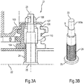
- 3A shows a sectional side view of a clothes dryer 21 in the region of attachment of a compressor 103 to a floor assembly 22 made of plastic.
- 3B shows a bolt 23 for fastening the compressor 103 to the floor assembly 22.
- the bolt 23 is pressed from below into a tubular or sleeve-shaped mounting region 24 of the bottom group 22.
- the bolt 23 has a flange on the foot side 25 as a stop against the bottom group 22. In order to lock the bolt 23 against rotation, this can be laterally circumferentially provided with notches 26 and so on.
- the bolt 23 may have a paragraph 8. On its side facing away from the bottom group 22, the bolt 23 also has an external thread 9 for screwing on a nut 108.
- 4A shows a sectional side view of a clothes dryer 31 in the region of attachment of a compressor 103 to a bottom group 32 made of plastic.
- 4B shows in a view obliquely from above a bolt 33 for attachment of the compressor 103 to the bottom group 32nd
- the bolt 33 has an external thread 34 at its front portion. He also has the rear of a screw head 35, so that can be dispensed with the self-contained nut 108.
- a shaft 38 of the bolt is slipped over an additional metal tube 36, by means of which the bolt 33 is supported on an edge of the mounting portion 37.
- a washer 107 is additionally provided between screw head 35 and metal tube 36.
- radial notches or the like can be used. (O. Fig.)
- the mounting portion 37 and / or the washer 107 may be provided to lock against rotation.
- FIG.5A shows a sectional side view of a clothes dryer 41 in the region of attachment of a compressor 103 to a bottom group 42 made of plastic.
- FIG.5B shows in a view obliquely from above a bolt 43 for attachment of the compressor 103 to the bottom group 42.
- the bolt has similar to the bolt 33 at its front portion an external thread 44 and at its other end a screw head 35.
- no metal pipe is now available.
- a tubular fastening region 45 of the base group 42, into which the bolt 43 can be screwed, is so far advanced that the washer 107 can be supported directly on an end edge of the fastening region 45.
- Figure 6 shows in a view obliquely from above a section of the bottom group 2 of the tumble dryer 1 in a provided for receiving the compressor 103 trough-like area.
- Figure 7 shows in a view obliquely from above another section of the bottom group 2 in the space provided for receiving the compressor 103 area.
- Figure 8 shows the intended for receiving the compressor 103 area of the floor assembly 2 fragmentary in a view obliquely from below.
- the three attachment regions 5 are introduced into shell-like structures or regions 51 of the floor assembly 2, which in turn transition into a rib-like, in particular honeycomb, structure 52.
- the attachment areas 5 are "flow-oriented" connected to the environment in order to absorb the forces that are introduced by the compressor 103 in the bottom group 2, effective in light construction.
- U-shaped or trapezoidal bead profiles can be used.
- the floor assembly 2 in particular on its shell-like regions 51 and / or on its rib-like structure 52, can be provided with a plastic material (also of another material, for example of glass fiber reinforced plastic).
- the plastic material may e.g. welded or glued.
- adhesives e.g. vibration-absorbing adhesives suitable.
- concrete and possibly reinforcement can be introduced into the floor assembly 2, in particular into its shell-like regions 51 and / or into its rib-like structure 52, for example for stiffening or even for replacement thereof. On can be realized as an improved insulation and vibration absorption.
- foam, styrofoam, potting compound, tar, etc. may be incorporated into the underbody 2, in particular into its shell-like regions 51 and / or into its rib-like structure 52, e.g. for a stiffener. On can be realized as an improved insulation and vibration absorption.
- a metal shell can also be used with the fourth and fifth embodiments.
- Fig.6 to 8 also be used with the second to fifth embodiments.
- a number may include exactly the specified number as well as a usual tolerance range, as long as this is not explicitly excluded.
Abstract
Ein Wäschetrocknungsgerät (1) weist eine Bodengruppe und einen Antrieb (103) einer Wärmepumpe auf, welcher Antrieb (103) mit mehreren elastischen Grommets (104) verbunden ist und die Grommets (104) mittels Bolzen (3), die durch die Grommets (104) hindurchgeführt sind, an der Bodengruppe (2) befestigt sind, wobei die Grommets (104) direkt auf der Bodengruppe (2) aufliegen und wobei die jeweiligen Bolzen (33) Schraubbolzen (3) sind, die einen vorderen, mit einem ersten Außengewinde (4a) versehenen Abschnitt (4) und einen rückwärtigen, mit einem rückwärtigen Außengewinde (9a) versehenen Abschnitt (9) aufweisen, mit ihrem vorderen Abschnitt (4) in die Befestigungsbereiche (5) eingeschraubt sind und mit ihrem rückwärtigen Abschnitt (9) das zugehörige Grommet (104) fixieren. Die Erfindung ist insbesondere vorteilhaft anwendbar auf Wäschetrockner und Waschtrockner mit einem Kompressor als Antrieb.

Description
Die Erfindung betrifft ein Wäschetrocknungsgerät, aufweisend eine Bodengruppe und einen Antrieb einer Wärmepumpe, welcher Antrieb mit mehreren elastischen Grommets verbunden ist und die Grommets mittels Bolzen, die durch die Grommets hindurchgeführt sind, an der Bodengruppe befestigt sind. Die Erfindung ist insbesondere vorteilhaft anwendbar auf Wäschetrockner und Waschtrockner mit einem Kompressor als Antrieb.The invention relates to a laundry drying apparatus, comprising a bottom group and a drive of a heat pump, which drive is connected to a plurality of elastic Grommets and Grommets are attached by means of bolts which are passed through the grommets to the floor assembly. The invention is particularly advantageously applicable to tumble dryer and washer-dryer with a compressor as a drive.
Jedoch sind diese Anordnungen vergleichsweise kostenintensiv sowie wenig vielseitig in Bezug auf eine Positionierung sowie der mechanischen Eigenschaften der Anbindung des Antriebs an die Bodengruppe.However, these arrangements are relatively expensive and not very versatile in terms of positioning and the mechanical properties of the connection of the drive to the floor assembly.
Aus den Druckschriften
Es ist die Aufgabe der vorliegenden Erfindung, die Nachteile des Standes der Technik zumindest teilweise zu überwinden.It is the object of the present invention to at least partially overcome the disadvantages of the prior art.
Diese Aufgabe wird gemäß den Merkmalen der unabhängigen Patentansprüche gelöst. Bevorzugte fakultative Ausführungsformen sind insbesondere den abhängigen Patentansprüchen, nachfolgender Beschreibung und beigefügter Zeichnung entnehmbar.This object is achieved according to the features of the independent claims. Preferred optional embodiments are in particular the dependent claims, the following description and attached drawing removable.
Die Aufgabe wird gelöst durch ein Wäschetrocknungsgerät, aufweisend eine Bodengruppe und einen Antrieb einer Wärmepumpe, welcher Antrieb mit mehreren elastischen Grommets verbunden ist und die Grommets mittels Bolzen, die durch die Grommets hindurchgeführt sind, an der Bodengruppe befestigt sind, wobei die Grommets direkt auf der Bodengruppe aufliegen.The object is achieved by a clothes drying apparatus, comprising a bottom group and a drive of a heat pump, which drive is connected to a plurality of elastic Grommets and the Grommets are attached by means of bolts which are passed through the Grommets to the floor assembly, the Grommets directly on the Floor group rest.
Folglich kann auf die bisher übliche Metallplatte oder den bisher üblichen Metallrahmen verzichtet werden. Dadurch wiederum können sowohl die Komplexität des Aufbaus als auch die Kosten reduziert werden. Insgesamt ergibt sich zudem eine höhere Flexibilität in der Positionierung des Antriebs. Ferner wird es durch den Verzicht der Metallplatte ermöglicht Steifigkeit aus dem System zu nehmen und gleichzeitig über Kunststoffstrukturen Dämpfung in das System einzubringen. Daraus ergeben sich akustische Vorteile während des Betriebs.Consequently, can be dispensed with the hitherto conventional metal plate or the usual metal frame. This, in turn, can reduce both the complexity of the design and the cost. Overall, there is also greater flexibility in the positioning of the drive. In addition, the omission of the metal plate makes it possible to remove rigidity from the system and, at the same time, introduce damping into the system via plastic structures. This results in acoustic advantages during operation.
Das Wäschetrocknungsgerät ist insbesondere ein Wäschetrockner oder ein kombiniertes Wasch-/Trocknungsgerät ("Waschtrockner"). Das Wäschetrocknungsgerät ist insbesondere ein Haushaltsgerät. Das Wäschetrocknungsgerät ist insbesondere ein Umlufttrockner mit einem umlaufenden Prozessluftkreislauf.The laundry drying apparatus is in particular a tumble dryer or a combined washing / drying appliance ("washer-dryer"). The laundry drying apparatus is in particular a household appliance. The laundry drying device is in particular a recirculating air dryer with a circulating process air cycle.
Unter einer Bodengruppe wird insbesondere eine Lagerungs- oder Trägerkomponente zur Befestigung mehrerer funktionaler Komponenten des Wäschetrocknungsgeräts wie eines Antriebs, mindestens eines Wärmetauschers, einer Kondensatwanne usw. verstanden. Die Bodengruppe ist bodenseitig in dem Wäschetrocknungsgerät angeordnet. Sie weist insbesondere einen Grundkörper aus Kunststoff auf und mag auch ganz aus Kunststoff bestehen.Under a floor assembly is in particular a storage or support component for fixing a plurality of functional components of the laundry drying apparatus such as a drive, at least one heat exchanger, a condensate tray, etc. understood. The bottom group is arranged on the bottom side in the laundry drying device. In particular, it has a base made of plastic and may also consist entirely of plastic.
Der Antrieb der Wärmepumpe kann für den Fall einer Kompressor-Wärmepumpe ein Kompressor sein. Jedoch kann z.B. auch eine Stirling-Wärmepumpe oder eine Vuilleumier-Wärmepumpe mit entsprechenden Antrieben verwendet werden.The drive of the heat pump may be a compressor in the case of a compressor heat pump. However, e.g. Also, a Stirling heat pump or a Vuilleumier heat pump can be used with appropriate drives.
Der Antrieb ist indirekt über die elastischen Grommets mit der Bodengruppe verbunden bzw. liegt indirekt über die elastischen Grommets auf der Bodengruppe auf.The drive is connected indirectly via the elastic Grommets with the bottom group or lies indirectly on the elastic grommets on the floor assembly.
Unter einem Grommet kann insbesondere ein Ring oder eine Tülle verstanden werden. Die Grommets können aus Gummi bestehen.Under a Grommet can be understood in particular a ring or a spout. The grommets can be made of rubber.
Der Bolzen kann ein Steckbolzen oder ein Schraubbolzen (Schraube) sein.The bolt can be a socket pin or a bolt (screw).
Der Bolzen kann über eine Unterlegscheibe auf dem Grommet aufliegen, insbesondere auf das Grommet drücken. Mittels des Bolzens kann das Grommet gegen die an Widerleger dienende Bodengruppe bewegt werden. Dadurch kann das Grommet zusammengedrückt werden, braucht es aber nicht. Insbesondere kann der Bolzen die Bodengruppe und eine Unterlegscheibe, welche das Grommet zwischen sich aufweisen, insbesondere halten, aufeinander zubewegen.The bolt can rest over a washer on the Grommet, in particular press on the Grommet. By means of the bolt, the Grommet can be moved against the bottom group serving to repelers. This can compress the Grommet, but it does not need it. In particular, the bolt, the bottom group and a washer, which have the Grommet between them, in particular hold, move towards each other.
Der Antrieb kann beispielsweise lösbar oder unlösbar in die Grommets eingerastet, eingeklemmt und/oder auf die Grommets aufgezogen sein. Dazu kann das Grommet seitliche Aufnahmerücksprünge aufweisen, z.B. ringnutartige Rücksprünge. Der Antrieb kann z.B. in einen Rücksprung des jeweiligen Grommets eingebracht worden sein. Alternativ oder zusätzlich kann der Antrieb durch die Bolzen auf die jeweiligen Grommets aufgedrückt werden.The drive can, for example, be releasably or non-releasably locked into the grommets, clamped and / or mounted on the grommets. For this purpose, the Grommet can have lateral receiving recesses, eg ringnutartige recesses. The drive can eg have been introduced in a return of each Grommets. Alternatively or additionally, the drive can be pressed by the bolts on the respective Grommets.
Es ist eine Ausgestaltung, dass die jeweiligen Bolzen in zumindest innenseitig hülsenförmige Befestigungsbereiche der Bodengruppe aus Kunststoff oder Metall eingebracht sind. Die Befestigungsbereiche ermöglichen eine lange Kontaktfläche mit dem Bolzen und eine zuverlässige Aufnahme des Bolzens.It is an embodiment that the respective bolts are inserted into at least inside sleeve-shaped attachment areas of the bottom group of plastic or metal. The attachment areas allow a long contact surface with the bolt and a reliable recording of the bolt.
Es ist eine Weiterbildung, dass die Bolzen ein Außengewinde zum Aufschrauben einer, insbesondere selbstsichernden, Mutter aufweisen. Auch kann der Bolzen einen z.B. ringförmigen Absatz zum Auflegen einer Unterlegscheibe aufweisen. Die Mutter und die Unterlegscheibe können dazu verwendet werden, das Grommet gegen ein Abheben von der Bodengruppe zu sichern und/oder das Grommet gegen die Bodengruppe zu drücken.It is a further development that the bolts have an external thread for screwing on a, in particular self-locking, nut. Also, the bolt may be a e.g. have annular shoulder for placing a washer. The nut and washer can be used to secure the grommet against lifting off the underbody and / or to push the grommet against the underbody.
Die hülsenförmigen Befestigungsbereiche können zumindest teilweise in das Durchgangsloch des Grommets eingesteckt sein, um eine präzise und zuverlässige Positionierung des Grommets zu bewirken. Dies kann auch so gesehen werden, dass das Grommet auf einen Teilabschnitt des hülsenförmigen Befestigungsbereichs aufgesteckt sein kann.The sleeve-shaped attachment portions may be at least partially plugged into the through hole of the Grommet to effect a precise and reliable positioning of the Grommet. This can also be seen that the Grommet can be plugged onto a portion of the sleeve-shaped mounting portion.
Die hülsenförmigen Befestigungsbereiche der Bodengruppe können ganz aus Kunststoff bestehen, was Herstellungskosten senkt.The sleeve-shaped mounting portions of the floor assembly can be made entirely of plastic, which reduces manufacturing costs.
Es ist noch eine Ausgestaltung, dass die Befestigungsbereiche zumindest innenseitig als Metallhülsen ausgebildet sind, die in Kunststoff der Bodengruppe eingebettet sind. So lässt sich eine besonders hohe Zuverlässigkeit des Befestigungsbereichs erreichen. Zudem können dadurch besonders hohe Kräfte von den Bolzen in die Befestigungsbereiche eingeleitet werden. Die Metallhülsen können innenliegende Schraubgewinde bzw. Innengewinde aufweisen. Um eine Drehung der Metallhülsen zu verhindern, können diese außenseitig mit Vorsprüngen oder Rücksprüngen (z.B. Rippen oder Einkerbungen) versehen sein und/oder nicht rotationssymmetrisch ausgebildet sein. Die Metallhülsen können bei der Herstellung der Bodengruppe mit dem Kunststoff des Grundkörpers der Bodengruppe umspritzt werden.It is still an embodiment that the attachment areas are formed at least on the inside as metal sleeves, which are embedded in plastic of the bottom group. Thus, a particularly high reliability of the mounting area can be achieved. In addition, particularly high forces can be introduced by the bolts in the attachment areas. The metal sleeves may have internal screw thread or internal thread. To prevent rotation of the metal sleeves, they may be provided on the outside with projections or recesses (eg ribs or indentations) and / or not rotationally symmetrical. The metal sleeves can be encapsulated in the manufacture of the bottom group with the plastic of the base body of the bottom group.
Es ist eine weitere Ausgestaltung, dass eine Hülse, insbesondere Metallhülse, einem Schaft des Bolzens übergestülpt ist, welche Hülse auf dem Befestigungsbereich, insbesondere einem Rand davon, aufliegt. So kann auf besonders zuverlässige Weise eine Steifigkeit der Verbindung zwischen dem Antrieb und der Bodengruppe erhöht werden. Es ist eine Weiterbildung, dass die Hülse an ihrem anderen Rand auf einer Unterlegscheibe aufliegt, die z.B. durch den Bolzen in Richtung der Bodengruppe gedrückt wird.It is a further embodiment that a sleeve, in particular metal sleeve, is slipped over a shaft of the bolt, which sleeve rests on the fastening area, in particular an edge thereof. Thus, a rigidity of the connection between the drive and the floor assembly can be increased in a particularly reliable manner. It is a further development that the sleeve rests on its other edge on a washer, which, e.g. is pressed by the bolt in the direction of the floor assembly.
Es ist noch eine weitere Ausgestaltung, dass eine zwischen dem Bolzen und dem Grommet befindliche Unterlegscheibe direkt auf dem Befestigungsbereich der Bodengruppe aufliegt. So wird eine erhöhte Steifigkeit der Verbindung zwischen dem Antrieb und der Bodengruppe ohne Zusatzelemente wie eine Hülse o.ä. erreicht. Der Befestigungsbereich kann dazu bis zu der Unterlegscheibe vorgezogen sein. Insbesondere kann der Befestigungsbereich durch das ganze Durchgangsloch des Grommets reichen. Alternativ kann der Bolzen direkt auf dem Befestigungsbereich aufliegen, z.B. mit einem Schraubkopf oder einem Flansch.It is yet another embodiment that a washer located between the bolt and the Grommet rests directly on the mounting area of the floor assembly. Thus, an increased rigidity of the connection between the drive and the floor assembly without additional elements such as a sleeve o.ä. reached. The attachment area may be pulled forward to the washer. In particular, the attachment area may extend through the entire through hole of the grommet. Alternatively, the bolt may rest directly on the mounting area, e.g. with a screw head or a flange.
Es ist ferner eine Ausgestaltung, dass die Bolzen Schraubbolzen sind, die in die Befestigungsbereiche eingeschraubt sind. Dazu kann der Bolzen ein Außengewinde aufweisen, z.B. an seinem vorderen Endabschnitt. So kann eine Befestigung der Schraubbolzen in der Bodengruppe durch Handhabung von oben erreicht werden.It is also an embodiment that the bolts are bolts that are screwed into the mounting areas. For this purpose, the bolt may have an external thread, e.g. at its front end portion. Thus, a fastening of the bolts in the floor assembly can be achieved by handling from above.
Es ist eine Ausgestaltung, dass die jeweiligen Bolzen Schraubbolzen sind, die einen vorderen, mit einem ersten Außengewinde versehenen Abschnitt und einen rückwärtigen, mit einem zweiten Außengewinde versehenen Abschnitt aufweisen, mit ihrem vorderen Abschnitt in die Befestigungsbereiche eingeschraubt sind und mit ihrem rückwärtigen Abschnitt das zugehörige Grommet fixieren. Diese Ausgestaltung ergibt den Vorteil, dass eine einfache Befestigung an der Bodengruppe und zudem eine Fixierung des Grommets durch jeweilige Verschraubungsvorgänge erreichbar ist. Zudem sind so die Befestigung an der Bodengruppe und die Fixierung des Grommets unabhängig voneinander einstellbar, z.B. deren Schraubkraft. Ein weitere Vorteil besteht darin, dass der Befestigungsbereich der Bodengruppe, in welchen der Schraubbolzen mit seinem ersten Außengewinde einschraubbar ist, wahlweise als durchgehende Bohrung oder als nicht durchgehendes Sackloch aufführbar ist. Das erste Außengewinde kann in ein Innengewinde des Befestigungsbereichs eingreifen oder als selbstschneidendes Gewinde ausgebildet sein. Das erste Außengewinde kann direkt in das Material der Bodengruppe eingeschraubt sein oder, wie auch weiter unten beschrieben, oder in eine in die Bodengruppe eingebrachte (durchgehende oder nicht gehende) Hülse eingeschraubt sein.It is an embodiment that the respective bolts are bolt bolts having a front portion provided with a first external thread and a rear portion provided with a second externally threaded portion are screwed with their front portion into the mounting portions and with their rear portion thereof Fix Grommet. This embodiment provides the advantage that a simple attachment to the floor assembly and also a fixation of Grommets can be achieved by respective Verschraubungsvorgänge. In addition, the attachment to the floor assembly and the fixation of Grommets are independently adjustable, eg their screwing force. Another advantage is that the attachment region of the floor assembly in which the bolt is screwed with its first external thread, either as a through hole or as a non-continuous blind hole is performed. The first external thread can engage in an internal thread of the fastening region or be formed as a self-tapping thread. The The first external thread can be screwed directly into the material of the floor assembly or, as also described below, or screwed into a introduced into the bottom group (continuous or non-going) sleeve.
Das erste Außengewinde und das zweite Außengewinde können gleich oder verschieden ausgebildet sein. Beispielsweise können das erste Außengewinde und das zweite Außengewinde ein Rechtsgewinde und ein Linksgewinde sein, einen unterschiedlichen Durchmesser aufweisen (z.B. kann das zweite Außengewinde einen geringeren Durchmesser aufweisen) und/oder eine unterschiedliche Steigung aufweisen usw.The first external thread and the second external thread may be the same or different. For example, the first external thread and the second external thread may be a right-hand thread and a left-hand thread, have a different diameter (e.g., the second external thread may have a smaller diameter), and / or have a different pitch, etc.
Es ist noch eine Ausgestaltung, dass der vordere Abschnitt und der rückwärtige Abschnitt durch einen Einschraubungsabschnitt getrennt sind. Der Einschraubungsabschnitt dient dem Eingriff durch ein Verschraubungsmittel zum Drehen des Schraubbolzens, z.B. durch einen Schraubenschlüssel. Der Einschraubungsabschnitt kann insbesondere eine eckige Außenkontur aufweisen, z.B. eine sechseckige Außenkontur usw.It is still a configuration that the front portion and the rear portion are separated by a screw-in portion. The threaded portion is for engagement by a bolting means for rotating the bolt, e.g. through a wrench. The screwed-in section may, in particular, have an angular outer contour, e.g. a hexagonal outer contour, etc.
Es ist noch eine Ausgestaltung, dass der vordere Abschnitt von dem Einschraubungsabschnitt durch einen - insbesondere ringartigen oder scheibenartigen - Schraubenflansch getrennt ist. Mittels des Schraubenflanschs kann sich der Schraubbolzen besonders zuverlässig und präzise an der Bodengruppe abstützen. Es ist eine zur Verhinderung einer Verdrehung oder Rotation des in die Bodengruppe eingeschraubten und auf der Bodengruppe aufliegenden Schraubbolzens vorteilhafte Ausgestaltung, dass an einer dem vordere Abschnitt zugewandten Unterseite des Schraubenflanschs Einkerbungen vorhanden sind.It is still an embodiment that the front portion of the screwed portion is separated by a - particular ring-like or disc-like - screw flange. By means of the screw flange, the bolt can be particularly reliable and precisely supported on the floor assembly. It is an advantageous embodiment for preventing a rotation or rotation of the screwed into the floor assembly and resting on the floor group bolt that notches are present on an underside facing the front portion of the screw.
Es ist noch eine Ausgestaltung, dass der Einschraubungsabschnitt einen Absatz zu dem rückwärtigen Abschnitt hin bereitstellt. Dies ergibt den Vorteil, dass auf diesen Absatz eine Unterlegscheibe auflegbar ist. Die Unterlegscheibe kann beispielsweise mit einer selbstsichernden Mutter gesichert werden, um ein Abheben des Kompressors zu unterbinden.It is still another aspect that the screw-in portion provides a shoulder toward the rear portion. This provides the advantage that a washer can be placed on this paragraph. The washer can be secured, for example, with a self-locking nut to prevent lifting of the compressor.
Es ist auch eine Ausgestaltung, dass die jeweiligen Bolzen Steckbolzen sind, die durch die Bodengruppe, insbesondere einen zugehörigen Befestigungsbereich, und das Grommet hindurchgesteckt sind. Dadurch kann ein Schraubvorgang zur Einbringung in die Bodengruppe vermieden werden. Die Steckbolzen können einerseits an der Bodengruppe und andererseits an dem Grommet oder einer dazwischenliegenden Unterlegscheibe aufliegen, insbesondere befestigt sein.It is also an embodiment that the respective bolts are locking pins, which are inserted through the bottom group, in particular an associated mounting portion, and the Grommet. This allows a screwing for insertion in the floor group can be avoided. The locking pins can rest on the one hand on the floor assembly and on the other hand on the Grommet or an intermediate washer, in particular be secured.
Der Steckbolzen kann insbesondere mit der Komponente, in die er zuerst eingeführt worden ist, in Anschlag stehen. Wird der Steckbolzen also zuerst von unten durch die Bodengruppe und dann durch das Grommet gesteckt, wirkt die Bodengruppe als Anschlag. Wird der Steckbolzen zuerst von oben durch das Grommet oder eine Unterlagescheibe gesteckt, wirkt das Grommet bzw. die Unterlegscheibe als Anschlag. Vorderseitig kann der Steckbolzen ein Außengewinde zum Aufschrauben einer Mutter aufweisen.The locking pin can in particular with the component in which it has been introduced first, stop. If the pin is first inserted from below through the floor assembly and then through the grommet, the floor assembly acts as a stop. If the locking pin is first inserted through the Grommet or a washer from above, the Grommet or washer acts as a stop. The front side of the socket pin may have an external thread for screwing a nut.
Es ist außerdem eine Ausgestaltung, dass die Bolzen seitlich vorstehende Vorsprünge oder Flansche zur Auflage auf der Bodengruppe oder an einer Unterlegscheibe aufweisen. So kann eine besonders sichere und zuverlässige Verbindung erreicht werden.It is also an embodiment that the bolts have laterally protruding projections or flanges for resting on the floor assembly or on a washer. So a particularly secure and reliable connection can be achieved.
Es ist zudem eine Ausgestaltung, dass die Bodengruppe eine schalenförmige Struktur und/oder eine rippenartige Struktur zur Aufnahme von durch die Bolzen eingebrachten Kräften aufweist. Solche Strukturen sind bei geringem Gewicht sehr stabil. Zudem kann ihre Steifigkeit einfach eingestellt werden, z.B. mittels Variation ihrer Größe, Wandstärke usw.It is also an embodiment that the bottom group has a cup-shaped structure and / or a rib-like structure for receiving forces introduced by the bolts. Such structures are very stable at low weight. In addition, their rigidity can be easily adjusted, e.g. by varying their size, wall thickness, etc.
Es ist zudem auch eine Ausgestaltung, dass die Bodengruppe, insbesondere ihre schalenförmige Struktur und/oder eine rippenartige Struktur, zumindest teilweise verfüllt ist. Dadurch lassen Steifigkeit, Dämpfung und Geräuschoptimierung noch vielseitiger umsetzen.It is also an embodiment that the bottom group, in particular its shell-shaped structure and / or a rib-like structure, at least partially filled. This allows even more versatile implementation of stiffness, damping and noise optimization.
Das Verfüllen kann z.B. durch Ankleben, Anschweißen usw. von Kunststoffmaterial (auch aus einem anderen Material als dem der Bodengruppe, z.B. aus glasfaserverstärktem Kunststoff) erreicht werden. Als Klebemittel sind z.B. schwingungsabsorbierende Klebemassen geeignet.The filling can e.g. by gluing, welding, etc. of plastic material (also of a material other than that of the floor assembly, for example of fiberglass reinforced plastic). As adhesives, e.g. vibration-absorbing adhesives suitable.
Auch kann die Bodengruppe mit Beton und ggf. Bewehrung verfüllt werden.Also, the floor assembly can be filled with concrete and possibly reinforcement.
Ferner kann die Bodengruppe mit Schaum, Styropor, Silikon, Kunststoff, Teer usw. verfüllt werden.Furthermore, the floor group with foam, polystyrene, silicone, plastic, tar, etc. are filled.
Die oben beschriebenen Eigenschaften, Merkmale und Vorteile dieser Erfindung sowie die Art und Weise, wie diese erreicht werden, werden klarer und deutlicher verständlich im Zusammenhang mit der folgenden schematischen Beschreibung eines Ausführungsbeispiels, das im Zusammenhang mit den Figuren der beigefügten Zeichnung näher erläutert wird:
- Fig.1A
- zeigt als Schnittdarstellung in Seitenansicht ausschnittsweise einen Wäschetrockner gemäß einem ersten Ausführungsbeispiel im Bereich einer Befestigung eines Kompressors an einer Bodengruppe;
- Fig.1B
- zeigt in einer Ansicht von schräg oben einen Bolzen des Wäschetrockners gemäß dem ersten Ausführungsbeispiel zur Befestigung des Kompressors an der Bodengruppe;
- Fig.2A
- zeigt als Schnittdarstellung in Seitenansicht ausschnittsweise einen Wäschetrockner gemäß einem zweiten Ausführungsbeispiel im Bereich einer Befestigung eines Kompressors an einer Bodengruppe;
- Fig.2B
- zeigt in einer Ansicht von schräg oben einen Bolzen und eine Metallhülse des Wäschetrockners gemäß dem zweiten Ausführungsbeispiel zur Befestigung des Kompressors an der Bodengruppe;
- Fig.3A
- zeigt als Schnittdarstellung in Seitenansicht ausschnittsweise einen Wäschetrockner gemäß einem dritten Ausführungsbeispiel im Bereich einer Befestigung eines Kompressors an einer Bodengruppe;
- Fig.3B
- zeigt in einer Ansicht von schräg oben einen Bolzen des Wäschetrockners gemäß dem dritten Ausführungsbeispiel zur Befestigung des Kompressors an der Bodengruppe;
- Fig.4A
- zeigt als Schnittdarstellung in Seitenansicht ausschnittsweise einen Wäschetrockner gemäß einem vierten Ausführungsbeispiel im Bereich einer Befestigung eines Kompressors an einer Bodengruppe;
- Fig.4B
- zeigt in einer Ansicht von schräg oben einen Bolzen des Wäschetrockners gemäß dem vierten Ausführungsbeispiel zur Befestigung des Kompressors an der Bodengruppe;
- Fig.5A
- zeigt als Schnittdarstellung in Seitenansicht ausschnittsweise einen Wäschetrockner gemäß einem fünften Ausführungsbeispiel im Bereich einer Befestigung eines Kompressors an einer Bodengruppe;
- Fig.5B
- zeigt in einer Ansicht von schräg oben einen Bolzen des Wäschetrockners gemäß dem fünften Ausführungsbeispiel zur Befestigung des Kompressors an der Bodengruppe;
- Fig.6
- zeigt in einer Ansicht von schräg oben einen Ausschnitt aus der Bodengruppe des Wäschetrockners gemäß einem ersten Ausführungsbeispiel in einem zur Aufnahme des Kompressors vorgesehenen Bereich;
- Fig.7
- zeigt in einer Ansicht von schräg oben einen weiteren Ausschnitt aus der Bodengruppe aus
Fig.7 in dem zur Aufnahme des Kompressors vorgesehenen Bereich; - Fig.8
- zeigt den zur Aufnahme des Kompressors vorgesehenen Bereich aus
Fig.7 ausschnittsweise in einer Ansicht von schräg unten; und - Fig.9
- zeigt in Schrägansicht einen Ausschnitt aus einem Wäschetrockner im Bereich eines Kompressors mit einem Metallblech.
- 1A
- shows a sectional side view in partial detail of a tumble dryer according to a first embodiment in the region of attachment of a compressor to a floor assembly;
- 1B
- shows in a view obliquely from above a bolt of the clothes dryer according to the first embodiment for attaching the compressor to the floor assembly;
- 2A
- shows a sectional side view in partial detail of a tumble dryer according to a second embodiment in the region of attachment of a compressor to a floor assembly;
- 2B
- shows in a view obliquely from above a bolt and a metal sleeve of the tumble dryer according to the second embodiment for attaching the compressor to the floor assembly;
- 3A
- shows a sectional side view in partial detail of a tumble dryer according to a third embodiment in the region of attachment of a compressor to a floor assembly;
- 3B
- shows in a view obliquely from above a bolt of the clothes dryer according to the third embodiment for attaching the compressor to the floor assembly;
- 4A
- shows a sectional side view in partial detail of a tumble dryer according to a fourth embodiment in the region of attachment of a compressor to a floor assembly;
- 4B
- shows in a view obliquely from above a bolt of the clothes dryer according to the fourth embodiment for attaching the compressor to the floor assembly;
- 5A
- shows a sectional side view in partial detail of a clothes dryer according to a fifth embodiment in the region of a fastening of a compressor to a floor assembly;
- FIG.5B
- shows in a view obliquely from above a bolt of the clothes dryer according to the fifth embodiment for attaching the compressor to the floor assembly;
- Figure 6
- shows in a view obliquely from above a section of the bottom group of the tumble dryer according to a first embodiment in a space provided for receiving the compressor area;
- Figure 7
- shows in a view obliquely from above another section of the floor group
Figure 7 in the area provided for receiving the compressor; - Figure 8
- shows the intended area for receiving the compressor area
Figure 7 partially in an oblique view from below; and - Figure 9
- shows an oblique view of a section of a tumble dryer in the range of a compressor with a metal sheet.
Der Bolzen 3 weist an einem vorderen Abschnitt 4 ein Außengewinde 4a auf und ist folglich dort als eine Schraube ausgebildet. Der Bolzen 3 wird von oben bzw. von innen in einen rohr- oder hülsenartigen Befestigungsbereich 5 der Bodengruppe 2 eingeschraubt. Der Bolzen 3 weist einen seitlich vorstehenden Absatz oder Schraubenflansch 6 auf, der sich auf einem oberseitigen Rand des Befestigungsbereichs 5 abstützt. Der Befestigungsbereich 5 kann optional in ein Durchgangsloch 110 des Grommets 104, durch das auch der Bolzen 3 verläuft, hineinragen und dient dann auch der sichereren Positionierung des Grommets 104.The
Um das nötige Drehmoment für die Einschraubung auf einfache Weise aufbringen zu können, kann beispielsweise ein Verschraubungsbereich 7 in Form eines Außensechskants (wie gezeigt), eines Innensechskants, eines Innentorx oder eines Kreuzschlitzes usw. in einem Kopf des Bolzens 3 vorgesehen sein.In order to apply the necessary torque for screwing in a simple manner, for example, a
Ein weiterer Absatz 8 dient dazu, eine Unterlegscheibe 107 aufzulegen. Die Unterlegscheibe 107 kann mit einer selbstsichernden Mutter 108 zu befestigen, um ein Abheben des Kompressors 103 zu unterbinden, z.B. analog zu dem Wäschetrockner 101. Die Mutter 108 ist auf ein weiteres, an einem rückwärtigen Bereich 9 des Bolzens 3 vorhandenes Außengewinde 9a aufschraubbar. Das Grommet 104 wird also zwischen der Bodengruppe 2 und der Unterlegscheibe 107 gehalten bzw. fixiert.Another
Um den Bolzen 3 gegen Rotation zu sperren, können an einer gewindeseitigen Unterseite des Schraubenflanschs 6, auf dem der Rand des Einschraubbereichs 5 aufliegt, Einkerbungen (o. Abb.) vorgesehen sein.In order to lock the
Der vordere Abschnitt 4 ist also durch den Einschraubungsabschnitt 7 von dem rückwärtigen Abschnitt 9 getrennt und von dem Einschraubungsabschnitt 7 durch den Schraubenflansch 6 getrennt.The
Das Grommet 104 liegt direkt auf einem Kunststoffbereich der Bodengruppe 12 auf. Die Metallbuchse 14 kann optional in das Durchgangsloch 110 des Grommets 104 hineinragen. Die Metallbuchse 14 dient dann auch der sichereren Positionierung des Grommets 104.The
Die Metallbuchse 14 ist mit einem Innengewinde ausgerüstet und an einem Befestigungsbereich 15 in die aus Kunststoff bestehende Bodengruppe 12 eingebettet, z.B. eingespritzt, eingepresst, mit Ultraschall eingebettet und/oder eingeschweißt usw. Der Bolzen 13 wird in die Metallbuchse 14 eingeschraubt. Der Bolzen 13 unterscheidet sich dabei ggf. nur durch die Art seines Außengewindes 16 von dem Bolzen 3. Um die Metallbuchse 14 gegen Rotation zu sperren, kann sie außenseitig von der kreiszylindrischen Form abweisen, z.B. indem sie nicht rotationssymmetrisch gestaltet ist, Längsrippen aufweist usw.The
Der Bolzen 23 wird hier von unten in einen rohr- oder hülsenförmigen Befestigungsbereich 24 der Bodengruppe 22 eingepresst. Der Bolzen 23 weist fußseitig einen Flansch 25 als Anschlag gegenüber der Bodengruppe 22 auf. Um den Bolzen 23 gegen Rotation zu sperren, kann dieser seitlich umlaufend mit Einkerbungen 26 usw. versehen sein.The
Auch der Bolzen 23 kann einen Absatz 8 aufweisen. An seiner der Bodengruppe 22 abgewandten Seite weist der Bolzen 23 ebenfalls ein Außengewinde 9 zum Aufschrauben einer Mutter 108 auf.Also, the
Der Bolzen 33 weist an seinem vorderen Abschnitt ein Außengewinde 34 auf. Er weist ferner rückwärtig einen Schraubenkopf 35 auf, so dass auf die eigenständige Mutter 108 verzichtet werden kann. Einem Schaft 38 des Bolzens ist ein zusätzliches Metallrohr 36 übergestülpt, mittels dessen sich der Bolzen 33 auf einem Rand des Befestigungsbereichs 37 abstützt. Zwischen Schraubenkopf 35 und Metallrohr 36 ist zusätzlich eine Unterlegscheibe 107 vorgesehen. Auch hierbei können radiale Einkerbungen o.ä. (o. Abb.) an dem Schraubenkopf 35, dem Befestigungsbereich 37 und/oder der Unterlegscheibe 107 vorgesehen sein, um gegen Rotation zu sperren.The
Die drei Befestigungsbereiche 5 sind in schalenartige Strukturen oder Bereiche 51 der Bodengruppe 2 eingebracht, die wiederum in eine rippenartige, insbesondere wabenartige, Struktur 52 übergehen. So werden die Befestigungsbereiche 5 "kraftflussgerecht" an die Umgebung angebunden, um die Kräfte, die durch den Kompressor 103 in die Bodengruppe 2 eingeleitet werden, effektiv bei leichter Bauweise aufzunehmen. Beispielsweise können u-förmige oder trapezförmige Sickenprofile verwendet werden.The three
In einer Weiterbildung kann die Bodengruppe 2, insbesondere an ihren schalenartigen Bereichen 51 und/oder an ihrer rippenartigen Struktur 52 mit einem Kunststoffmaterial (auch aus einem anderen Material, z.B. aus glasfaserverstärktem Kunststoff) versehen sein. Das Kunststoffmaterial kann z.B. angeschweißt oder angeklebt sein. Als Klebemittel sind z.B. schwingungsabsorbierende Klebemassen geeignet.In a further development, the
In einer anderen Weiterbildung kann Beton und ggf. Bewehrung in die Bodengruppe 2, insbesondere in ihre schalenartigen Bereiche 51 und/oder in ihre rippenartige Struktur 52 eingebracht werden, z.B. zur Versteifung oder sogar zu deren Ersatz. Auf kann so eine verbesserte Dämmung und Schwingungsaufnahme verwirklicht werden.In another development, concrete and possibly reinforcement can be introduced into the
In noch einer anderen Weiterbildung kann Schaum, Styropor, Vergussmasse, Teer usw. in die Bodengruppe 2, insbesondere in ihre schalenartigen Bereiche 51 und/oder in ihre rippenartige Struktur 52 eingebracht werden, z.B. für eine Versteifung. Auf kann so eine verbesserte Dämmung und Schwingungsaufnahme verwirklicht werden.In yet another embodiment, foam, styrofoam, potting compound, tar, etc., may be incorporated into the
Selbstverständlich ist die vorliegende Erfindung nicht auf das gezeigte Ausführungsbeispiel beschränkt.Of course, the present invention is not limited to the embodiment shown.
So können Merkmale der verschiedenen Ausführungsbeispiele auch kombiniert oder ausgetauscht werden. Beispielsweise kann eine Metallhülse auch mit den vierten und fünften Ausführungsbeispielen verwendet werden.Thus, features of the various embodiments can also be combined or replaced. For example, a metal shell can also be used with the fourth and fifth embodiments.
Zudem können die
Allgemein kann unter "ein", "eine" usw. eine Einzahl oder eine Mehrzahl verstanden werden, insbesondere im Sinne von "mindestens ein" oder "ein oder mehrere" usw., solange dies nicht explizit ausgeschlossen ist, z.B. durch den Ausdruck "genau ein" usw.Generally, "on", "an", etc. may be taken to mean a singular or a plurality, in particular in the sense of "at least one" or "one or more" etc., unless this is explicitly excluded, e.g. by the expression "exactly one", etc.
Auch kann eine Zahlenangabe genau die angegebene Zahl als auch einen üblichen Toleranzbereich umfassen, solange dies nicht explizit ausgeschlossen ist.Also, a number may include exactly the specified number as well as a usual tolerance range, as long as this is not explicitly excluded.
- 11
- Wäschetrocknerclothes dryer
- 22
- Bodengruppeunderbody
- 33
- Bolzenbolt
- 44
- Vorderer Abschnitt des BolzensFront section of the bolt
- 4a4a
- Außengewindeexternal thread
- 55
- Befestigungsbereichfastening area
- 66
- Schraubenflanschscrew flange
- 77
- VerschraubungsbereichVerschraubungsbereich
- 88th
- Absatzparagraph
- 99
- Rückwärtiger Abschnitt des BolzensRear section of the bolt
- 9a9a
- Außengewindeexternal thread
- 1111
- Wäschetrocknerclothes dryer
- 1212
- Bodengruppeunderbody
- 1313
- Bolzenbolt
- 1414
- Metallbuchsemetal bushing
- 1515
- Befestigungsbereichfastening area
- 1616
- Außengewindeexternal thread
- 2121
- Wäschetrocknerclothes dryer
- 2222
- Bodengruppeunderbody
- 2323
- Bolzenbolt
- 2424
- Befestigungsbereichfastening area
- 2525
- Flanschflange
- 2626
- Einkerbungnotch
- 3131
- Wäschetrocknerclothes dryer
- 3232
- Bodengruppeunderbody
- 3333
- Bolzenbolt
- 3434
- Außengewindeexternal thread
- 3535
- Schraubenkopfscrew head
- 3636
- Metallrohrmetal pipe
- 3737
- Befestigungsbereichfastening area
- 3838
- Schaftshaft
- 4141
- Wäschetrocknerclothes dryer
- 4242
- Bodengruppeunderbody
- 4343
- Bolzenbolt
- 4444
- Außengewindeexternal thread
- 4545
- Befestigungsbereichfastening area
- 5151
- Schalenartiger BereichPeel-like area
- 5252
- Rippenartige StrukturRib-like structure
- 101101
- Wäschetrocknerclothes dryer
- 102102
- Bodengruppeunderbody
- 103103
- Kompressorcompressor
- 104104
- GrommetGrommet
- 105105
- Bolzenbolt
- 106106
- Metallplattemetal plate
- 107107
- Unterlegscheibewasher
- 108108
- Muttermother
- 109109
- Umlaufender RücksprungAll-round return
- 110110
- DurchgangslochThrough Hole
Claims (12)
Priority Applications (1)
| Application Number | Priority Date | Filing Date | Title |
|---|---|---|---|
| PL17163068T PL3235943T3 (en) | 2016-04-19 | 2017-03-27 | Laundry drying device with heat pump and its drive |
Applications Claiming Priority (1)
| Application Number | Priority Date | Filing Date | Title |
|---|---|---|---|
| DE102016206525.4A DE102016206525A1 (en) | 2016-04-19 | 2016-04-19 | Clothes drying machine with heat pump and associated drive |
Publications (2)
| Publication Number | Publication Date |
|---|---|
| EP3235943A1 true EP3235943A1 (en) | 2017-10-25 |
| EP3235943B1 EP3235943B1 (en) | 2019-02-27 |
Family
ID=58428190
Family Applications (1)
| Application Number | Title | Priority Date | Filing Date |
|---|---|---|---|
| EP17163068.4A Active EP3235943B1 (en) | 2016-04-19 | 2017-03-27 | Laundry drying device with heat pump and its drive |
Country Status (4)
| Country | Link |
|---|---|
| EP (1) | EP3235943B1 (en) |
| CN (1) | CN107354696B (en) |
| DE (1) | DE102016206525A1 (en) |
| PL (1) | PL3235943T3 (en) |
Cited By (1)
| Publication number | Priority date | Publication date | Assignee | Title |
|---|---|---|---|---|
| US10976063B2 (en) | 2019-02-19 | 2021-04-13 | Carrier Corporation | Vibration reducing grommet |
Families Citing this family (3)
| Publication number | Priority date | Publication date | Assignee | Title |
|---|---|---|---|---|
| DE102017123316A1 (en) * | 2017-10-09 | 2018-11-15 | Miele & Cie. Kg | Stationary household appliance, preferably heat pump tumble dryer |
| DE102018207641A1 (en) * | 2018-05-16 | 2019-11-21 | BSH Hausgeräte GmbH | Compressor bracket and method for mounting a compressor bracket |
| CN110804841B (en) * | 2018-08-06 | 2022-05-13 | 无锡小天鹅电器有限公司 | Support damping device and washing machine with same |
Citations (10)
| Publication number | Priority date | Publication date | Assignee | Title |
|---|---|---|---|---|
| US6499714B1 (en) * | 2001-10-04 | 2002-12-31 | John R. Wike | System for and method of mounting compressors |
| JP2007143736A (en) | 2005-11-25 | 2007-06-14 | Toshiba Corp | Clothes drying machine |
| JP2008088919A (en) | 2006-10-03 | 2008-04-17 | Toshiba Corp | Heat pump mechanism and drum type washing dryer having the same |
| JP2010057545A (en) | 2008-09-01 | 2010-03-18 | Toshiba Corp | Washing-drying machine |
| US20100107703A1 (en) * | 2005-07-26 | 2010-05-06 | Kabushiki Kaisha Toshiba | Drum-type washer/dryer |
| US20110154676A1 (en) | 2009-12-29 | 2011-06-30 | Electrolux Home Products Corporation N.V. | Home Laundry Drier with Releasably Securable Vibration Damper |
| EP2559804A1 (en) | 2011-08-18 | 2013-02-20 | BSH Electrodomésticos España, S.A. | Household appliance comprising a driving unit for a heat pump |
| EP2743394A1 (en) | 2012-12-14 | 2014-06-18 | Electrolux Home Products Corporation N.V. | Heat pump laundry treatment apparatus |
| EP2743395A1 (en) | 2012-12-14 | 2014-06-18 | Electrolux Home Products Corporation N.V. | Heat pump laundry treatment apparatus |
| DE102013226398A1 (en) * | 2013-12-18 | 2015-06-18 | BSH Hausgeräte GmbH | Household appliance comprising a functional part mounted on a level base |
Family Cites Families (4)
| Publication number | Priority date | Publication date | Assignee | Title |
|---|---|---|---|---|
| KR100443568B1 (en) * | 2002-08-19 | 2004-08-09 | 대영이앤비 주식회사 | Fixing device for compressor of cooling apparatus |
| JP2008000260A (en) * | 2006-06-21 | 2008-01-10 | Toshiba Corp | Drum washing machine |
| CN102493161B (en) * | 2011-10-19 | 2016-08-03 | 青岛海尔滚筒洗衣机有限公司 | A kind of fixed installation structure reducing heat pump module vibrating noise |
| CN204476726U (en) * | 2015-02-04 | 2015-07-15 | 浙江博莱特制冷设备有限公司 | A kind of motor side unit damping device of refrigeration compressor |
-
2016
- 2016-04-19 DE DE102016206525.4A patent/DE102016206525A1/en not_active Withdrawn
-
2017
- 2017-03-27 PL PL17163068T patent/PL3235943T3/en unknown
- 2017-03-27 EP EP17163068.4A patent/EP3235943B1/en active Active
- 2017-04-17 CN CN201710249316.8A patent/CN107354696B/en active Active
Patent Citations (10)
| Publication number | Priority date | Publication date | Assignee | Title |
|---|---|---|---|---|
| US6499714B1 (en) * | 2001-10-04 | 2002-12-31 | John R. Wike | System for and method of mounting compressors |
| US20100107703A1 (en) * | 2005-07-26 | 2010-05-06 | Kabushiki Kaisha Toshiba | Drum-type washer/dryer |
| JP2007143736A (en) | 2005-11-25 | 2007-06-14 | Toshiba Corp | Clothes drying machine |
| JP2008088919A (en) | 2006-10-03 | 2008-04-17 | Toshiba Corp | Heat pump mechanism and drum type washing dryer having the same |
| JP2010057545A (en) | 2008-09-01 | 2010-03-18 | Toshiba Corp | Washing-drying machine |
| US20110154676A1 (en) | 2009-12-29 | 2011-06-30 | Electrolux Home Products Corporation N.V. | Home Laundry Drier with Releasably Securable Vibration Damper |
| EP2559804A1 (en) | 2011-08-18 | 2013-02-20 | BSH Electrodomésticos España, S.A. | Household appliance comprising a driving unit for a heat pump |
| EP2743394A1 (en) | 2012-12-14 | 2014-06-18 | Electrolux Home Products Corporation N.V. | Heat pump laundry treatment apparatus |
| EP2743395A1 (en) | 2012-12-14 | 2014-06-18 | Electrolux Home Products Corporation N.V. | Heat pump laundry treatment apparatus |
| DE102013226398A1 (en) * | 2013-12-18 | 2015-06-18 | BSH Hausgeräte GmbH | Household appliance comprising a functional part mounted on a level base |
Cited By (1)
| Publication number | Priority date | Publication date | Assignee | Title |
|---|---|---|---|---|
| US10976063B2 (en) | 2019-02-19 | 2021-04-13 | Carrier Corporation | Vibration reducing grommet |
Also Published As
| Publication number | Publication date |
|---|---|
| CN107354696B (en) | 2021-02-19 |
| EP3235943B1 (en) | 2019-02-27 |
| CN107354696A (en) | 2017-11-17 |
| DE102016206525A1 (en) | 2017-10-19 |
| PL3235943T3 (en) | 2019-08-30 |
Similar Documents
| Publication | Publication Date | Title |
|---|---|---|
| EP3235943B1 (en) | Laundry drying device with heat pump and its drive | |
| DE102017000900B4 (en) | Fastening arrangement for a vehicle | |
| EP2532568B1 (en) | Device to attach a component, e.g. a railing, to a vehicle body. | |
| DE102018211471B3 (en) | battery case | |
| EP3586018B1 (en) | Fastening device and fastening assembly | |
| DE202015009723U1 (en) | Vehicle wheel with a rim and a wheel disc | |
| DE102007048975A1 (en) | Quick fastening device | |
| WO2005083279A1 (en) | Crankshaft arrangement and structural part for said crankshaft arrangement | |
| EP3133305B1 (en) | Cage nut | |
| EP2108545B1 (en) | Assembly for attaching a profile, in particular a hollow profile, to a vehicle roof | |
| EP2195480B1 (en) | Washing machine | |
| EP1612432B1 (en) | Fastening assembly for a trim panel and fastening method | |
| DE112019001836B4 (en) | Mounting plate for fixed, running and swivel castors | |
| DE102018201607A1 (en) | Air strut compound with a motor vehicle body | |
| DE102009016239A1 (en) | Fastening element for fastening vehicle light at vehicle body, has hollow cylindrical case provided with internal thread, external thread and propellant, and nut provided with nut internal thread that is fitted to external thread of case | |
| EP3851686B1 (en) | Lightweight fastener | |
| DE3114283A1 (en) | Plastic fastening element, in particular for the releasable fastening of flat workpieces | |
| DE19915491C2 (en) | Star base, especially for an IV pole | |
| WO2005097581A1 (en) | Hollow support | |
| DE202005005501U1 (en) | Quick release nut for e.g. fastening spare wheel to vehicle trunk, has internal threads arranged opposite to inner smooth sides of through-hole that is inclined at certain angle to nut axis | |
| DE102015009376B4 (en) | Component of a motor vehicle and method for assembling a component | |
| AT412334B (en) | FUEL TANK FOR A VEHICLE | |
| EP1033449B1 (en) | Cantilevered support for attachment of uprights to the floor carrying frame of a balcony | |
| EP3631214A1 (en) | Force transmission assembly and insert | |
| EP3586017A1 (en) | Fastening device and fastening assembly |
Legal Events
| Date | Code | Title | Description |
|---|---|---|---|
| PUAI | Public reference made under article 153(3) epc to a published international application that has entered the european phase |
Free format text: ORIGINAL CODE: 0009012 |
|
| STAA | Information on the status of an ep patent application or granted ep patent |
Free format text: STATUS: THE APPLICATION HAS BEEN PUBLISHED |
|
| AK | Designated contracting states |
Kind code of ref document: A1 Designated state(s): AL AT BE BG CH CY CZ DE DK EE ES FI FR GB GR HR HU IE IS IT LI LT LU LV MC MK MT NL NO PL PT RO RS SE SI SK SM TR |
|
| AX | Request for extension of the european patent |
Extension state: BA ME |
|
| STAA | Information on the status of an ep patent application or granted ep patent |
Free format text: STATUS: REQUEST FOR EXAMINATION WAS MADE |
|
| 17P | Request for examination filed |
Effective date: 20180425 |
|
| RBV | Designated contracting states (corrected) |
Designated state(s): AL AT BE BG CH CY CZ DE DK EE ES FI FR GB GR HR HU IE IS IT LI LT LU LV MC MK MT NL NO PL PT RO RS SE SI SK SM TR |
|
| GRAP | Despatch of communication of intention to grant a patent |
Free format text: ORIGINAL CODE: EPIDOSNIGR1 |
|
| STAA | Information on the status of an ep patent application or granted ep patent |
Free format text: STATUS: GRANT OF PATENT IS INTENDED |
|
| RIC1 | Information provided on ipc code assigned before grant |
Ipc: D06F 37/20 20060101ALN20180831BHEP Ipc: D06F 58/20 20060101AFI20180831BHEP |
|
| INTG | Intention to grant announced |
Effective date: 20181008 |
|
| GRAS | Grant fee paid |
Free format text: ORIGINAL CODE: EPIDOSNIGR3 |
|
| GRAA | (expected) grant |
Free format text: ORIGINAL CODE: 0009210 |
|
| STAA | Information on the status of an ep patent application or granted ep patent |
Free format text: STATUS: THE PATENT HAS BEEN GRANTED |
|
| AK | Designated contracting states |
Kind code of ref document: B1 Designated state(s): AL AT BE BG CH CY CZ DE DK EE ES FI FR GB GR HR HU IE IS IT LI LT LU LV MC MK MT NL NO PL PT RO RS SE SI SK SM TR |
|
| REG | Reference to a national code |
Ref country code: GB Ref legal event code: FG4D Free format text: NOT ENGLISH |
|
| REG | Reference to a national code |
Ref country code: CH Ref legal event code: EP |
|
| REG | Reference to a national code |
Ref country code: AT Ref legal event code: REF Ref document number: 1101498 Country of ref document: AT Kind code of ref document: T Effective date: 20190315 |
|
| REG | Reference to a national code |
Ref country code: IE Ref legal event code: FG4D Free format text: LANGUAGE OF EP DOCUMENT: GERMAN |
|
| REG | Reference to a national code |
Ref country code: DE Ref legal event code: R096 Ref document number: 502017000806 Country of ref document: DE |
|
| REG | Reference to a national code |
Ref country code: NL Ref legal event code: MP Effective date: 20190227 |
|
| REG | Reference to a national code |
Ref country code: LT Ref legal event code: MG4D |
|
| PG25 | Lapsed in a contracting state [announced via postgrant information from national office to epo] |
Ref country code: PT Free format text: LAPSE BECAUSE OF FAILURE TO SUBMIT A TRANSLATION OF THE DESCRIPTION OR TO PAY THE FEE WITHIN THE PRESCRIBED TIME-LIMIT Effective date: 20190627 Ref country code: SE Free format text: LAPSE BECAUSE OF FAILURE TO SUBMIT A TRANSLATION OF THE DESCRIPTION OR TO PAY THE FEE WITHIN THE PRESCRIBED TIME-LIMIT Effective date: 20190227 Ref country code: FI Free format text: LAPSE BECAUSE OF FAILURE TO SUBMIT A TRANSLATION OF THE DESCRIPTION OR TO PAY THE FEE WITHIN THE PRESCRIBED TIME-LIMIT Effective date: 20190227 Ref country code: NO Free format text: LAPSE BECAUSE OF FAILURE TO SUBMIT A TRANSLATION OF THE DESCRIPTION OR TO PAY THE FEE WITHIN THE PRESCRIBED TIME-LIMIT Effective date: 20190527 Ref country code: LT Free format text: LAPSE BECAUSE OF FAILURE TO SUBMIT A TRANSLATION OF THE DESCRIPTION OR TO PAY THE FEE WITHIN THE PRESCRIBED TIME-LIMIT Effective date: 20190227 Ref country code: NL Free format text: LAPSE BECAUSE OF FAILURE TO SUBMIT A TRANSLATION OF THE DESCRIPTION OR TO PAY THE FEE WITHIN THE PRESCRIBED TIME-LIMIT Effective date: 20190227 |
|
| PG25 | Lapsed in a contracting state [announced via postgrant information from national office to epo] |
Ref country code: BG Free format text: LAPSE BECAUSE OF FAILURE TO SUBMIT A TRANSLATION OF THE DESCRIPTION OR TO PAY THE FEE WITHIN THE PRESCRIBED TIME-LIMIT Effective date: 20190527 Ref country code: IS Free format text: LAPSE BECAUSE OF FAILURE TO SUBMIT A TRANSLATION OF THE DESCRIPTION OR TO PAY THE FEE WITHIN THE PRESCRIBED TIME-LIMIT Effective date: 20190627 Ref country code: GR Free format text: LAPSE BECAUSE OF FAILURE TO SUBMIT A TRANSLATION OF THE DESCRIPTION OR TO PAY THE FEE WITHIN THE PRESCRIBED TIME-LIMIT Effective date: 20190528 Ref country code: LV Free format text: LAPSE BECAUSE OF FAILURE TO SUBMIT A TRANSLATION OF THE DESCRIPTION OR TO PAY THE FEE WITHIN THE PRESCRIBED TIME-LIMIT Effective date: 20190227 Ref country code: HR Free format text: LAPSE BECAUSE OF FAILURE TO SUBMIT A TRANSLATION OF THE DESCRIPTION OR TO PAY THE FEE WITHIN THE PRESCRIBED TIME-LIMIT Effective date: 20190227 Ref country code: RS Free format text: LAPSE BECAUSE OF FAILURE TO SUBMIT A TRANSLATION OF THE DESCRIPTION OR TO PAY THE FEE WITHIN THE PRESCRIBED TIME-LIMIT Effective date: 20190227 |
|
| PG25 | Lapsed in a contracting state [announced via postgrant information from national office to epo] |
Ref country code: SK Free format text: LAPSE BECAUSE OF FAILURE TO SUBMIT A TRANSLATION OF THE DESCRIPTION OR TO PAY THE FEE WITHIN THE PRESCRIBED TIME-LIMIT Effective date: 20190227 Ref country code: RO Free format text: LAPSE BECAUSE OF FAILURE TO SUBMIT A TRANSLATION OF THE DESCRIPTION OR TO PAY THE FEE WITHIN THE PRESCRIBED TIME-LIMIT Effective date: 20190227 Ref country code: CZ Free format text: LAPSE BECAUSE OF FAILURE TO SUBMIT A TRANSLATION OF THE DESCRIPTION OR TO PAY THE FEE WITHIN THE PRESCRIBED TIME-LIMIT Effective date: 20190227 Ref country code: EE Free format text: LAPSE BECAUSE OF FAILURE TO SUBMIT A TRANSLATION OF THE DESCRIPTION OR TO PAY THE FEE WITHIN THE PRESCRIBED TIME-LIMIT Effective date: 20190227 Ref country code: IT Free format text: LAPSE BECAUSE OF FAILURE TO SUBMIT A TRANSLATION OF THE DESCRIPTION OR TO PAY THE FEE WITHIN THE PRESCRIBED TIME-LIMIT Effective date: 20190227 Ref country code: DK Free format text: LAPSE BECAUSE OF FAILURE TO SUBMIT A TRANSLATION OF THE DESCRIPTION OR TO PAY THE FEE WITHIN THE PRESCRIBED TIME-LIMIT Effective date: 20190227 Ref country code: ES Free format text: LAPSE BECAUSE OF FAILURE TO SUBMIT A TRANSLATION OF THE DESCRIPTION OR TO PAY THE FEE WITHIN THE PRESCRIBED TIME-LIMIT Effective date: 20190227 Ref country code: AL Free format text: LAPSE BECAUSE OF FAILURE TO SUBMIT A TRANSLATION OF THE DESCRIPTION OR TO PAY THE FEE WITHIN THE PRESCRIBED TIME-LIMIT Effective date: 20190227 |
|
| REG | Reference to a national code |
Ref country code: DE Ref legal event code: R097 Ref document number: 502017000806 Country of ref document: DE |
|
| PG25 | Lapsed in a contracting state [announced via postgrant information from national office to epo] |
Ref country code: LU Free format text: LAPSE BECAUSE OF NON-PAYMENT OF DUE FEES Effective date: 20190327 Ref country code: SM Free format text: LAPSE BECAUSE OF FAILURE TO SUBMIT A TRANSLATION OF THE DESCRIPTION OR TO PAY THE FEE WITHIN THE PRESCRIBED TIME-LIMIT Effective date: 20190227 |
|
| REG | Reference to a national code |
Ref country code: BE Ref legal event code: MM Effective date: 20190331 |
|
| PG25 | Lapsed in a contracting state [announced via postgrant information from national office to epo] |
Ref country code: MC Free format text: LAPSE BECAUSE OF FAILURE TO SUBMIT A TRANSLATION OF THE DESCRIPTION OR TO PAY THE FEE WITHIN THE PRESCRIBED TIME-LIMIT Effective date: 20190227 |
|
| PLBE | No opposition filed within time limit |
Free format text: ORIGINAL CODE: 0009261 |
|
| STAA | Information on the status of an ep patent application or granted ep patent |
Free format text: STATUS: NO OPPOSITION FILED WITHIN TIME LIMIT |
|
| PG25 | Lapsed in a contracting state [announced via postgrant information from national office to epo] |
Ref country code: IE Free format text: LAPSE BECAUSE OF NON-PAYMENT OF DUE FEES Effective date: 20190327 |
|
| 26N | No opposition filed |
Effective date: 20191128 |
|
| PG25 | Lapsed in a contracting state [announced via postgrant information from national office to epo] |
Ref country code: SI Free format text: LAPSE BECAUSE OF FAILURE TO SUBMIT A TRANSLATION OF THE DESCRIPTION OR TO PAY THE FEE WITHIN THE PRESCRIBED TIME-LIMIT Effective date: 20190227 Ref country code: BE Free format text: LAPSE BECAUSE OF NON-PAYMENT OF DUE FEES Effective date: 20190331 Ref country code: FR Free format text: LAPSE BECAUSE OF NON-PAYMENT OF DUE FEES Effective date: 20190427 |
|
| PG25 | Lapsed in a contracting state [announced via postgrant information from national office to epo] |
Ref country code: TR Free format text: LAPSE BECAUSE OF FAILURE TO SUBMIT A TRANSLATION OF THE DESCRIPTION OR TO PAY THE FEE WITHIN THE PRESCRIBED TIME-LIMIT Effective date: 20190227 |
|
| PG25 | Lapsed in a contracting state [announced via postgrant information from national office to epo] |
Ref country code: MT Free format text: LAPSE BECAUSE OF FAILURE TO SUBMIT A TRANSLATION OF THE DESCRIPTION OR TO PAY THE FEE WITHIN THE PRESCRIBED TIME-LIMIT Effective date: 20190227 |
|
| REG | Reference to a national code |
Ref country code: CH Ref legal event code: PL |
|
| PG25 | Lapsed in a contracting state [announced via postgrant information from national office to epo] |
Ref country code: CH Free format text: LAPSE BECAUSE OF NON-PAYMENT OF DUE FEES Effective date: 20200331 Ref country code: LI Free format text: LAPSE BECAUSE OF NON-PAYMENT OF DUE FEES Effective date: 20200331 |
|
| PG25 | Lapsed in a contracting state [announced via postgrant information from national office to epo] |
Ref country code: CY Free format text: LAPSE BECAUSE OF FAILURE TO SUBMIT A TRANSLATION OF THE DESCRIPTION OR TO PAY THE FEE WITHIN THE PRESCRIBED TIME-LIMIT Effective date: 20190227 |
|
| PG25 | Lapsed in a contracting state [announced via postgrant information from national office to epo] |
Ref country code: HU Free format text: LAPSE BECAUSE OF FAILURE TO SUBMIT A TRANSLATION OF THE DESCRIPTION OR TO PAY THE FEE WITHIN THE PRESCRIBED TIME-LIMIT; INVALID AB INITIO Effective date: 20170327 |
|
| PG25 | Lapsed in a contracting state [announced via postgrant information from national office to epo] |
Ref country code: MK Free format text: LAPSE BECAUSE OF FAILURE TO SUBMIT A TRANSLATION OF THE DESCRIPTION OR TO PAY THE FEE WITHIN THE PRESCRIBED TIME-LIMIT Effective date: 20190227 |
|
| REG | Reference to a national code |
Ref country code: DE Ref legal event code: R084 Ref document number: 502017000806 Country of ref document: DE |
|
| REG | Reference to a national code |
Ref country code: AT Ref legal event code: MM01 Ref document number: 1101498 Country of ref document: AT Kind code of ref document: T Effective date: 20220327 |
|
| PGFP | Annual fee paid to national office [announced via postgrant information from national office to epo] |
Ref country code: PL Payment date: 20230317 Year of fee payment: 7 Ref country code: GB Payment date: 20230323 Year of fee payment: 7 Ref country code: DE Payment date: 20230331 Year of fee payment: 7 |
|
| PG25 | Lapsed in a contracting state [announced via postgrant information from national office to epo] |
Ref country code: AT Free format text: LAPSE BECAUSE OF NON-PAYMENT OF DUE FEES Effective date: 20220327 |