EP3235774A1 - Rough terrain crane - Google Patents
Rough terrain crane Download PDFInfo
- Publication number
- EP3235774A1 EP3235774A1 EP15869592.4A EP15869592A EP3235774A1 EP 3235774 A1 EP3235774 A1 EP 3235774A1 EP 15869592 A EP15869592 A EP 15869592A EP 3235774 A1 EP3235774 A1 EP 3235774A1
- Authority
- EP
- European Patent Office
- Prior art keywords
- disposed
- control device
- emission control
- exhaust emission
- lower carrier
- Prior art date
- Legal status (The legal status is an assumption and is not a legal conclusion. Google has not performed a legal analysis and makes no representation as to the accuracy of the status listed.)
- Granted
Links
Images



Classifications
-
- B—PERFORMING OPERATIONS; TRANSPORTING
- B01—PHYSICAL OR CHEMICAL PROCESSES OR APPARATUS IN GENERAL
- B01D—SEPARATION
- B01D53/00—Separation of gases or vapours; Recovering vapours of volatile solvents from gases; Chemical or biological purification of waste gases, e.g. engine exhaust gases, smoke, fumes, flue gases, aerosols
- B01D53/34—Chemical or biological purification of waste gases
- B01D53/92—Chemical or biological purification of waste gases of engine exhaust gases
- B01D53/94—Chemical or biological purification of waste gases of engine exhaust gases by catalytic processes
- B01D53/9445—Simultaneously removing carbon monoxide, hydrocarbons or nitrogen oxides making use of three-way catalysts [TWC] or four-way-catalysts [FWC]
- B01D53/9454—Simultaneously removing carbon monoxide, hydrocarbons or nitrogen oxides making use of three-way catalysts [TWC] or four-way-catalysts [FWC] characterised by a specific device
-
- B—PERFORMING OPERATIONS; TRANSPORTING
- B66—HOISTING; LIFTING; HAULING
- B66C—CRANES; LOAD-ENGAGING ELEMENTS OR DEVICES FOR CRANES, CAPSTANS, WINCHES, OR TACKLES
- B66C23/00—Cranes comprising essentially a beam, boom, or triangular structure acting as a cantilever and mounted for translatory of swinging movements in vertical or horizontal planes or a combination of such movements, e.g. jib-cranes, derricks, tower cranes
- B66C23/62—Constructional features or details
-
- B—PERFORMING OPERATIONS; TRANSPORTING
- B01—PHYSICAL OR CHEMICAL PROCESSES OR APPARATUS IN GENERAL
- B01D—SEPARATION
- B01D53/00—Separation of gases or vapours; Recovering vapours of volatile solvents from gases; Chemical or biological purification of waste gases, e.g. engine exhaust gases, smoke, fumes, flue gases, aerosols
- B01D53/34—Chemical or biological purification of waste gases
- B01D53/92—Chemical or biological purification of waste gases of engine exhaust gases
- B01D53/94—Chemical or biological purification of waste gases of engine exhaust gases by catalytic processes
-
- B—PERFORMING OPERATIONS; TRANSPORTING
- B60—VEHICLES IN GENERAL
- B60K—ARRANGEMENT OR MOUNTING OF PROPULSION UNITS OR OF TRANSMISSIONS IN VEHICLES; ARRANGEMENT OR MOUNTING OF PLURAL DIVERSE PRIME-MOVERS IN VEHICLES; AUXILIARY DRIVES FOR VEHICLES; INSTRUMENTATION OR DASHBOARDS FOR VEHICLES; ARRANGEMENTS IN CONNECTION WITH COOLING, AIR INTAKE, GAS EXHAUST OR FUEL SUPPLY OF PROPULSION UNITS IN VEHICLES
- B60K13/00—Arrangement in connection with combustion air intake or gas exhaust of propulsion units
- B60K13/04—Arrangement in connection with combustion air intake or gas exhaust of propulsion units concerning exhaust
-
- B—PERFORMING OPERATIONS; TRANSPORTING
- B62—LAND VEHICLES FOR TRAVELLING OTHERWISE THAN ON RAILS
- B62D—MOTOR VEHICLES; TRAILERS
- B62D21/00—Understructures, i.e. chassis frame on which a vehicle body may be mounted
- B62D21/18—Understructures, i.e. chassis frame on which a vehicle body may be mounted characterised by the vehicle type and not provided for in groups B62D21/02 - B62D21/17
-
- B—PERFORMING OPERATIONS; TRANSPORTING
- B66—HOISTING; LIFTING; HAULING
- B66C—CRANES; LOAD-ENGAGING ELEMENTS OR DEVICES FOR CRANES, CAPSTANS, WINCHES, OR TACKLES
- B66C15/00—Safety gear
-
- B—PERFORMING OPERATIONS; TRANSPORTING
- B66—HOISTING; LIFTING; HAULING
- B66C—CRANES; LOAD-ENGAGING ELEMENTS OR DEVICES FOR CRANES, CAPSTANS, WINCHES, OR TACKLES
- B66C23/00—Cranes comprising essentially a beam, boom, or triangular structure acting as a cantilever and mounted for translatory of swinging movements in vertical or horizontal planes or a combination of such movements, e.g. jib-cranes, derricks, tower cranes
- B66C23/18—Cranes comprising essentially a beam, boom, or triangular structure acting as a cantilever and mounted for translatory of swinging movements in vertical or horizontal planes or a combination of such movements, e.g. jib-cranes, derricks, tower cranes specially adapted for use in particular purposes
- B66C23/36—Cranes comprising essentially a beam, boom, or triangular structure acting as a cantilever and mounted for translatory of swinging movements in vertical or horizontal planes or a combination of such movements, e.g. jib-cranes, derricks, tower cranes specially adapted for use in particular purposes mounted on road or rail vehicles; Manually-movable jib-cranes for use in workshops; Floating cranes
- B66C23/40—Cranes comprising essentially a beam, boom, or triangular structure acting as a cantilever and mounted for translatory of swinging movements in vertical or horizontal planes or a combination of such movements, e.g. jib-cranes, derricks, tower cranes specially adapted for use in particular purposes mounted on road or rail vehicles; Manually-movable jib-cranes for use in workshops; Floating cranes with a single prime mover for both crane and vehicle
-
- B—PERFORMING OPERATIONS; TRANSPORTING
- B66—HOISTING; LIFTING; HAULING
- B66C—CRANES; LOAD-ENGAGING ELEMENTS OR DEVICES FOR CRANES, CAPSTANS, WINCHES, OR TACKLES
- B66C23/00—Cranes comprising essentially a beam, boom, or triangular structure acting as a cantilever and mounted for translatory of swinging movements in vertical or horizontal planes or a combination of such movements, e.g. jib-cranes, derricks, tower cranes
- B66C23/18—Cranes comprising essentially a beam, boom, or triangular structure acting as a cantilever and mounted for translatory of swinging movements in vertical or horizontal planes or a combination of such movements, e.g. jib-cranes, derricks, tower cranes specially adapted for use in particular purposes
- B66C23/36—Cranes comprising essentially a beam, boom, or triangular structure acting as a cantilever and mounted for translatory of swinging movements in vertical or horizontal planes or a combination of such movements, e.g. jib-cranes, derricks, tower cranes specially adapted for use in particular purposes mounted on road or rail vehicles; Manually-movable jib-cranes for use in workshops; Floating cranes
- B66C23/42—Cranes comprising essentially a beam, boom, or triangular structure acting as a cantilever and mounted for translatory of swinging movements in vertical or horizontal planes or a combination of such movements, e.g. jib-cranes, derricks, tower cranes specially adapted for use in particular purposes mounted on road or rail vehicles; Manually-movable jib-cranes for use in workshops; Floating cranes with jibs of adjustable configuration, e.g. foldable
-
- F—MECHANICAL ENGINEERING; LIGHTING; HEATING; WEAPONS; BLASTING
- F01—MACHINES OR ENGINES IN GENERAL; ENGINE PLANTS IN GENERAL; STEAM ENGINES
- F01N—GAS-FLOW SILENCERS OR EXHAUST APPARATUS FOR MACHINES OR ENGINES IN GENERAL; GAS-FLOW SILENCERS OR EXHAUST APPARATUS FOR INTERNAL-COMBUSTION ENGINES
- F01N3/00—Exhaust or silencing apparatus having means for purifying, rendering innocuous, or otherwise treating exhaust
- F01N3/08—Exhaust or silencing apparatus having means for purifying, rendering innocuous, or otherwise treating exhaust for rendering innocuous
- F01N3/10—Exhaust or silencing apparatus having means for purifying, rendering innocuous, or otherwise treating exhaust for rendering innocuous by thermal or catalytic conversion of noxious components of exhaust
- F01N3/24—Exhaust or silencing apparatus having means for purifying, rendering innocuous, or otherwise treating exhaust for rendering innocuous by thermal or catalytic conversion of noxious components of exhaust characterised by constructional aspects of converting apparatus
- F01N3/28—Construction of catalytic reactors
-
- Y—GENERAL TAGGING OF NEW TECHNOLOGICAL DEVELOPMENTS; GENERAL TAGGING OF CROSS-SECTIONAL TECHNOLOGIES SPANNING OVER SEVERAL SECTIONS OF THE IPC; TECHNICAL SUBJECTS COVERED BY FORMER USPC CROSS-REFERENCE ART COLLECTIONS [XRACs] AND DIGESTS
- Y02—TECHNOLOGIES OR APPLICATIONS FOR MITIGATION OR ADAPTATION AGAINST CLIMATE CHANGE
- Y02A—TECHNOLOGIES FOR ADAPTATION TO CLIMATE CHANGE
- Y02A50/00—TECHNOLOGIES FOR ADAPTATION TO CLIMATE CHANGE in human health protection, e.g. against extreme weather
- Y02A50/20—Air quality improvement or preservation, e.g. vehicle emission control or emission reduction by using catalytic converters
Definitions
- the present invention relates to a rough terrain crane equipped with an exhaust emission control device and an elevating step, particularly, to a layout of the exhaust emission control device and the elevating step on a vehicle body.
- a rough terrain crane includes a carrier device that is capable of four-wheel driving and four-wheel steering, and exhibits excellent small-radius turning performance and rough terrain traveling performance.
- the rough terrain crane includes a single driver seat or operating unit, has special performance that enables an operator on the driver seat to drive a vehicle and to perform operation of a crane mounted on the vehicle.
- the rough terrain crane is manufactured based on a compact design so as to exhibit such special performance. Therefore, an entire vehicle body is designed to be short, an engine (in general, a diesel engine) is disposed on a rear side of the vehicle body, and an elevating step or an exhaust emission control device, which will be described below, is disposed around a fender (for example, see Patent Document 1).
- the exhaust emission of diesel engines contains particulate matter (hereinafter, referred to as "PM”), nitride oxide (hereinafter, referred to as “NOx”), or the like.
- the exhaust emission control device prevents the matter from being released into the air and prevents the air from being polluted.
- the exhaust emission control device includes, as the constituent elements, a diesel particulate filter (hereinafter, referred to as a "DPF”) for collecting the PM, a diesel oxidation catalyst (hereinafter referred to as "DOC”) for removing the NOx, a decomposition reactor tube (hereinafter referred to as "DRT”), and a selective catalytic reduction (hereinafter referred to as "SCR”).
- a desired exhaust emission control device is constituted (for example, see Patent Document 2).
- a front axle or a rear axle has a multi-axle structure, and a structure with a premise of attaching and detaching an outrigger and a boom to and from a vehicle-body frame is employed in some cases.
- the main reason for the front axle or the rear axle to have the multi-axis structure is to reduce the entirety of axle load to a certain load or lower.
- the reason for the structure with the premise of attaching and detaching the outrigger and the boom to and from the vehicle-body frame is employed is to be in accordance with the legislation of a country or a region where the large rough terrain crane is used.
- layout design of accessory machinery such as the exhaust emission control device and the elevating step has a low degree of freedom in utilizing a space around the fender.
- the large rough terrain crane lifts a load having a heavy weight, a counterweight, or the like, in addition to the boom and the outrigger, has a large size; however, in a circumstance, a vehicle body (particularly, a vehicle width) is not allowed to increase in size so as to maintain a compact size as a characteristic of the rough terrain crane, and thus a space, in which the exhaust emission control device or the like is to be disposed, is reduced.
- the present invention is made under such background, and an object thereof is to provide a large rough terrain crane in which an outrigger or a boom is freely attached and detached, as a compact rough terrain crane including an exhaust emission control device and an elevating step which are laid out in a compact manner without impairing excellent small-radius turning performance.
- the exhaust emission control device and the elevating step are disposed in a compact manner in a stacked stated between the top surface of the lower carrier and the lower surface of the counterweight, the attaching and detaching function of the outrigger and the boom in a compact manner and the excellent small-radius turning performance are not impaired even in the large rough terrain crane.
- FIG. 1 is a perspective view of a rough terrain crane 10 according to an embodiment of the present invention.
- the rough terrain crane 10 includes a lower carrier 11 and an upper working unit 12 disposed above the lower carrier 11.
- the lower carrier 11 includes a lower frame 13, and a front axle 14 and a rear axle 15 are provided on the lower frame 13.
- a diesel engine 20 (refer to FIGS. 2 and 3 ) as a drive source of the front axle 14 and the rear axle 15 are mounted on an upper side of a rear end portion of the lower frame 13.
- the diesel engine 20 includes an engine main body (not illustrated) and an engine cover 49 that covers the engine main body, and, in the embodiment, the diesel engine including the engine cover 49 is referred to as the diesel engine 20.
- Wheels 16 and 17 of the front axle 14 and the rear axle 15 are driven by the diesel engine 20 via a transmission not illustrated and is steered by a hydraulic actuator not illustrated.
- a front outrigger 18 and a rear outrigger 19 are mounted on a front end and a rear end of the lower frame 13, respectively, and overhang outward from the vehicle in order to maintain the stability of the vehicle during an operation of the upper working unit 12.
- the front outrigger 18 is connected to the front end of the lower frame 13 and is attachable to and detachable from the lower frame 13.
- the front outrigger 19 is connected to the rear end of the lower frame 13 and is attachable to and detachable from the lower frame 13. Note that the front outrigger 18, the rear outrigger 19, and the lower frame 13 are connected by a pin or other known means which is employed.
- the hydraulic actuator, a hydraulic actuator 29 provided in the upper working unit 12, or a hydraulic pump (not illustrated) that supplies hydraulic pressure to the hydraulic actuator (not illustrated) provided in the upper working unit 12 is provided in the upper frame 13.
- the hydraulic pump is driven by the diesel engine 20.
- the upper working unit 12 includes a slewing base 22 having the counterweight 28 (refer to FIG. 2 ) on the rear end so as to perform stable work of the upper working unit 12.
- the slewing base 22 is turnably mounted on the lower frame 13 through a slewing bearing (not illustrated).
- the boom device 23 is connected to the slewing base 22 via a boom-root fulcrum pin (not illustrated).
- the boom device 23 is supported to be undulated by the boom-root fulcrum pin.
- the boom device 23 undulates in response to expansion and contraction of the hydraulic actuator 29.
- An expansion boom 24 has an internally-installed hydraulic actuator (not illustrated), and operating of the hydraulic actuator causes the expansion boom to expand and contract.
- the boom device 23 has a winch 27 that is driven by a hydraulic motor (not illustrated), and operating of the winch 27 causes a work to move up and down.
- the boom device 23 is attachable to and detachable from the upper working unit 12.
- a single working unit 26 for driving the lower carrier 11 and operating the upper working unit 12 is supported on the lower carrier 11.
- the driving of the lower carrier 11 means driving and steering of the wheels 16 and 17 for causing the rough terrain crane 10 to travel.
- the operating of the upper driving unit 12 means the undulation and expansion and contraction (boom operation) of the boom device 23 via the hydraulic actuator 29 and the internally hydraulic actuator installed in the expansion boom 24.
- the rough terrain crane 10 is characterized in that an exhaust emission control device 30 is mounted to be adjacent to the diesel engine 20 in layout which will be described below, and an elevating step 46, which will be described below, is disposed in a gap 47 formed between the top surface 56 of the lower carrier 11 and the exhaust emission control device 30.
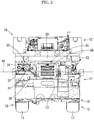
- FIG. 2 is a rear view of the rough terrain crane 10 according to the embodiment of the present invention.
- the exhaust emission control device 30 receives exhaust gas exhausted from the diesel engine 20 and control the same.
- the exhaust emission control device 30 is disposed on a left side when viewed from a vehicle rear side.
- the exhaust emission control device 30 is mounted to be adjacent to the diesel engine 20.
- the exhaust emission control device 30 is provided with a cover 34.
- the cover 34 protects the exhaust emission control device 30 from being exposed to rain and dust.
- FIG. 3 is a perspective view illustrating the exhaust emission control device 30 and the periphery of the diesel engine 20 in the lower carrier 11.
- FIG. 4 is a plan view illustrating the exhaust emission control device 30 and the periphery of the diesel engine 20 in the lower carrier 11.
- FIG. 5 is a side view illustrating the exhaust emission control device 30 and the periphery of the diesel engine 20 in the lower carrier 11. Note that the figures illustrate the layout of the exhaust emission control device 30 and the diesel engine 20, and the cover 34, the engine cover 49, or the like is omitted in the figures depending on views.
- the exhaust emission control device 30 includes a diesel oxidation catalyst (hereinafter, referred to as "DOC”) 31, a urea water tank 50 in which a predetermined reducing agent (urea water in the embodiment) is stored, selective catalyst reduction (hereinafter, referred to as “SCR”) 32 that reduces nitrogen oxide in the exhaust emission through the urea water, and a decompression reactor tube (hereinafter, referred to as "DRT”) 33 that supplies the urea water to the SCR 32.
- DOC diesel oxidation catalyst
- SCR selective catalyst reduction
- DTT decompression reactor tube
- the exhaust emission from the diesel engine 20 is first supplied to the DOC 31, passes the DRT 33 and the SCR 32 in this order, and is released as exhaust gas from a muffler 37 to the air.
- the DRT 33 is disposed downstream of the DOC 31
- the SCR 32 is disposed downstream of the DRT 33.
- the muffler 37 a device (muffling device) reduces sound produced when the exhaust gas is released, and is a part of the SCR 32.
- the DOC 31 is connected to the exhaust pipe 38 extending from the diesel engine 20.
- an end portion of the exhaust pipe 38 on the DOC 31 side is a position higher than an end portion of the exhaust pipe 38 on the diesel engine 20 side.
- the exhaust pipe 38 is inclined with respect to the exhaust emission control device 30 with a horizontal line 41 as a reference.
- the angle of inclination is 30°. Note that the angle of the inclination may be 30° or smaller.
- the structure of the DOC 31 is already known.
- the DOC 31 mainly aims at treating of unburned fuel (HC and the like) and carbon monoxide (CO) contained in the exhaust emission and oxidizing nitrogen monoxide (NO) to nitrogen dioxide (NO2) contained in the exhaust emission.
- the DOC 31 oxidizes CO to carbon dioxide (CO2) and burns HC as an increase in the exhaust gas temperature.
- the DOC 31 has a casing and the outer shape of the casing is a cylindrical shape.
- the center axis line of the DOC 31 is in a frontward-rearward direction of the vehicle, i.e., a longitudinal direction 39 of the lower frame 13.
- the exhaust emission from the exhaust pipe 38 flows on the front side of the DOC 31 in the longitudinal direction 39.
- the SCR 32 reacts with a reducing agent in the exhaust to reduce nitrogen oxide (NOX), and then finally converts the exhaust to a gas mixture of nitrogen (N2) and water (H2O) and emits the same to the atmosphere.
- NOX nitrogen oxide
- N2O nitrogen oxide
- the DRT 33 supplies urea water for reducing the NOX in the exhaust emission.
- hydrolysis occurs to generate ammonium (NH3), and then the NOX is reduced by the NH3.
- NH3 ammonium
- the DRT 33 includes a cylindrical pipe 42 and a supply valve 43 connected to the cylindrical pipe 42, and guides the urea water from the urea water tank 50.
- the supply valve 43 is connected to the urea water tank 50 via a pipe 53 and ejects the urea water into the cylindrical pipe 42 at a predetermined pressure.
- the DRT 33 is disposed in series with the DOC 31 in the longitudinal direction 39. In other words, the center axis line of the DRT 33 is in agreement with the center axis line of the DOC 31.
- the DRT 33 is disposed on the front side of the DOC 31 in the longitudinal direction 39 and extends in the forward direction. The exhaust emission passing through the DOC 31 flows in the longitudinal direction 39 to flow into the cylindrical pipe 42 of the DRT 33, and then receives the supply of the urea water from the supply valve 43.
- the SCR 32 has a casing and the outer shape thereof is formed into a cylindrical shape.
- the center axis line of the SCR 32 is parallel to the longitudinal direction 39 of the rough terrain crane 10.
- the SCR 32, the DOC 31, and the DRT 33 are disposed in parallel on a virtual horizontal plane 45 (refer to FIG. 5 ) that is widened in the longitudinal direction 39 and in a rightward-leftward direction of the vehicle, that is, a transverse direction 40 of the lower frame 13.
- the virtual horizontal plane 45 is positioned above the top surface 56 (refer to FIG. 6 ) of the lower carrier 11 by being separated from the top surface by a predetermined distance in a vertical direction.
- the vertical direction here indicates an orthogonal direction to both of the longitudinal direction 39 and transverse direction 40.
- the SCR 32 is disposed in parallel to the DOC 31 to face each other in the transverse direction 40, and a coupling pipe 44 is connected both of them, in which the coupling pipe is formed to be a substantial U shape.
- the exhaust emission passing through the DRT 33 enters the coupling pipe 44, and then makes a U-turn to enter the SCR 32 disposed downstream of the DRT 33.
- the exhaust emission is controlled to be discharged as N2 and H2O as described above.
- the urea water tank 50 illustrated in FIG. 3 is made of a material such as resin or stainless steel having high corrosion resistance against the urea water and excellent weather resistance and impact resistance.
- a material such as resin or stainless steel having high corrosion resistance against the urea water and excellent weather resistance and impact resistance.
- the shape of the urea water tank 50 is formed to have a substantially rectangular parallelepiped shape.
- FIG. 6 is a side view of the rough terrain crane 10 according to the embodiment of the present invention and a view illustrating the periphery of the elevating step 46.
- the urea water tank 50 is disposed on the rear side from a front-side axle of the rear axle 15, and on the front side from the rear-side axle thereof.
- the urea water tank 50 is disposed on the front side of the DOC 31, the DRT 33, and the SCR 32.
- the urea water tank 50 is disposed in the vicinity of the left side of the diesel engine 20 when viewed from the rear side of the vehicle.
- the urea water tank 50 is supported by a support base 54 fixed to the lower frame 13.
- the rough terrain crane 10 in order to easily supply the urea water to the urea water tank 50 and to easily make an access to the boom-root fulcrum pin during disassembly of the boom, the rough terrain crane 10 includes the exhaust emission control device 30 including the urea water tank 50 and the elevating step 46 in the vicinity of the root fulcrum pin.
- the elevating step 46 is made of a metal material such as aluminum.
- the elevating step 46 is formed to have horizontal members as scaffolds that are fixed, at regular intervals, to two longitudinal members disposed at intervals. Note that the elevating step 46 may be configured to freely expand and contract.
- the elevating step 46 is disposed on the top surface 56 of the lower carrier 11. In addition, at least a part of the elevating step 46 is disposed immediately below the exhaust emission control device 30. In other words, the elevating step 46 is disposed in the gap 47 that is formed between the upper surface 56 of the lower carrier 11 and the exhaust emission control device 30.
- the structure of the elevating step 46 is already known, and is connected to the top surface 56 via a pivot axis.
- the elevating step 46 is capable of slewing around the pivot axis, and can overhang to the side of the lower carrier 11.
- the elevating step 46 is bent in an intermediate portion 55, and thereby the elevating step 46 is in an upright locking state to the lower carrier 11.
- the counterweight 28 that is provided on the boom device 23 also increases in size. Therefore, a space in which the exhaust emission control device 30 and the elevating step 46 are to be disposed, that is, a space between the top surface 56 of the lower carrier 11 and the lower surface 35 (refer to FIG. 6 ) of the counterweight 28 is reduced.
- the exhaust emission control device 30 constituted thereof is reduced in size in the perpendicular direction, that is, the height direction of the lower carrier 11.
- the distance between the virtual horizontal plane 45 and the top surface 56 of the lower carrier 11 is easily secured in layout design of the elevating step 46, and thus the elevating step 46 can be disposed along with the exhaust emission control device 30 on the top surface 56 of the lower carrier 11 in a compact manner.
- the DOC 31 and the SCR 32 are disposed in parallel to each other; however, since the DRT 33 is bonded to the DOC 31 in series in the longitudinal direction 39, a size in a vehicle-width direction which is required for mounting the exhaust emission control device 30 is also reduced.
- the exhaust pipe 38 is inclined, and thereby an occurrence of overhanging of the exhaust emission control device 30 in the vehicle-width direction which is connected to the exhaust pipe is reduced. In other words, a size in the vehicle-width direction which is required for mounting the exhaust emission control device 30 is much more reduced.
- the exhaust emission control device 30 is disposed at the position adjacent to the left side of the diesel engine 20 when viewed from the vehicle-rear direction as illustrated in FIG. 2 ; however, the position is not limited thereto.
- the exhaust emission control device 30 may be disposed at a position adjacent to the right side of the diesel engine 20 when viewed from the vehicle-rear direction.
- the DRT 33 is disposed in series with the DOC 31 in the longitudinal direction 39; however, the DRT 33 may be disposed in series with the SCR 32 in the longitudinal direction 39. Specifically, the DRT 33 may be disposed downstream of the coupling pipe 44 and upstream of the SCR 32, and may be disposed in parallel to the DOC 31. The exhaust mission passing through the DOC 31 may flow to the DRT 33 through the coupling pipe 44.
- the DOC 31 and the SCR 32 are disposed in parallel to face each other in the transverse direction 40; however, the DOC 31 and the SCR 32 may not face each other in the transverse direction 40.
- the DOC 31 and the SCR 32 may be disposed in parallel to face each other in the longitudinal direction 39.
Landscapes
- Engineering & Computer Science (AREA)
- Chemical & Material Sciences (AREA)
- Mechanical Engineering (AREA)
- Chemical Kinetics & Catalysis (AREA)
- Combustion & Propulsion (AREA)
- Health & Medical Sciences (AREA)
- Transportation (AREA)
- General Chemical & Material Sciences (AREA)
- Oil, Petroleum & Natural Gas (AREA)
- Biomedical Technology (AREA)
- Environmental & Geological Engineering (AREA)
- Analytical Chemistry (AREA)
- Toxicology (AREA)
- General Engineering & Computer Science (AREA)
- Exhaust Gas After Treatment (AREA)
- Exhaust Gas Treatment By Means Of Catalyst (AREA)
- Cooling, Air Intake And Gas Exhaust, And Fuel Tank Arrangements In Propulsion Units (AREA)
- Body Structure For Vehicles (AREA)
- Control And Safety Of Cranes (AREA)
- Jib Cranes (AREA)
Abstract
Description
- The present invention relates to a rough terrain crane equipped with an exhaust emission control device and an elevating step, particularly, to a layout of the exhaust emission control device and the elevating step on a vehicle body.
- In general, a rough terrain crane includes a carrier device that is capable of four-wheel driving and four-wheel steering, and exhibits excellent small-radius turning performance and rough terrain traveling performance. The rough terrain crane includes a single driver seat or operating unit, has special performance that enables an operator on the driver seat to drive a vehicle and to perform operation of a crane mounted on the vehicle. The rough terrain crane is manufactured based on a compact design so as to exhibit such special performance. Therefore, an entire vehicle body is designed to be short, an engine (in general, a diesel engine) is disposed on a rear side of the vehicle body, and an elevating step or an exhaust emission control device, which will be described below, is disposed around a fender (for example, see Patent Document 1).
- The exhaust emission of diesel engines contains particulate matter (hereinafter, referred to as "PM"), nitride oxide (hereinafter, referred to as "NOx"), or the like. The exhaust emission control device prevents the matter from being released into the air and prevents the air from being polluted. The exhaust emission control device includes, as the constituent elements, a diesel particulate filter (hereinafter, referred to as a "DPF") for collecting the PM, a diesel oxidation catalyst (hereinafter referred to as "DOC") for removing the NOx, a decomposition reactor tube (hereinafter referred to as "DRT"), and a selective catalytic reduction (hereinafter referred to as "SCR"). By combining the constituent elements, a desired exhaust emission control device is constituted (for example, see Patent Document 2).
-
- [Patent Document 1] Japanese Patent Laid-open
2012-149535 - [Patent Document 2] Japanese Patent No.
4286888 - However, in a large rough terrain crane, a front axle or a rear axle has a multi-axle structure, and a structure with a premise of attaching and detaching an outrigger and a boom to and from a vehicle-body frame is employed in some cases. The main reason for the front axle or the rear axle to have the multi-axis structure is to reduce the entirety of axle load to a certain load or lower. In addition, the reason for the structure with the premise of attaching and detaching the outrigger and the boom to and from the vehicle-body frame is employed is to be in accordance with the legislation of a country or a region where the large rough terrain crane is used. In other words, in some countries or regions, strict weight limit (axle load limit) is imposed on a vehicle traveling on a public road. Therefore, when the large rough terrain crane runs on a public road, the vehicle body, the outrigger, and the boom must be individually transported on a trailer in some cases.
- In the large terrain crane employing the premise of attaching and detaching the outrigger or the boom, layout design of accessory machinery such as the exhaust emission control device and the elevating step has a low degree of freedom in utilizing a space around the fender. In other words, since the large rough terrain crane lifts a load having a heavy weight, a counterweight, or the like, in addition to the boom and the outrigger, has a large size; however, in a circumstance, a vehicle body (particularly, a vehicle width) is not allowed to increase in size so as to maintain a compact size as a characteristic of the rough terrain crane, and thus a space, in which the exhaust emission control device or the like is to be disposed, is reduced.
- The present invention is made under such background, and an object thereof is to provide a large rough terrain crane in which an outrigger or a boom is freely attached and detached, as a compact rough terrain crane including an exhaust emission control device and an elevating step which are laid out in a compact manner without impairing excellent small-radius turning performance.
-
- (1) In order to achieve the object described above, a rough terrain crane according to the present invention includes: a lower carrier having a front axle and a rear axle; a boom device disposed above the lower carrier; and a single operating unit that performs driving and a boom operation via a hydraulic actuator. The lower carrier includes a lower frame, an outrigger provided to be freely attached and detached to an end portion of the lower frame, and an engine that is disposed on an upper side of a rear end portion of the lower carrier, drives the axles, and supplies hydraulic pressure to the hydraulic actuator, and an elevating step. An exhaust emission control device is mounted to have a diesel oxidation catalyst which is connected to an exhaust pipe extending from the engine and is supplied with exhaust, a decompression reactor tube disposed downstream of the diesel oxidation catalyst, and a selective catalyst reduction disposed downstream of the decompression reactor tube. The diesel oxidation catalyst, the decompression reactor tube, and the selective catalyst reduction are disposed in parallel on a virtual horizontal plane separated from a top surface of the lower carrier by a predetermined distance, and the elevating step is disposed in a gap that is formed between the top surface of the lower carrier and the exhaust emission control device.
In the large rough terrain crane having a structure in which the outrigger is freely attached and detached, a counterweight that is provided on the boom device increases in size. Therefore, a space in which the exhaust emission control device and the elevating step are to be disposed, that is, a space between the top surface of the lower carrier and a lower surface of the counterweight of the lower carrier, is reduced. However, according to the present invention, since the diesel oxidation catalyst, the decompression reactor tube, and the selective catalyst reduction are disposed in parallel on the virtual horizontal plane, the exhaust emission control device constituted thereof is reduced in size in a perpendicular direction, that is, a height direction of the lower carrier. Hence, the predetermined distance is easily secured in the layout design of the elevating step, and thus the elevating step can be disposed along with the exhaust emission control device on the top surface of the lower carrier in a compact manner. - (2) In the rough terrain crane, it is preferable that the decompression reactor tube be disposed in series with the diesel oxidation catalyst or the selective catalyst reduction in a longitudinal direction of the lower frame, and the diesel oxidation catalyst and the selective catalyst reduction be disposed in parallel to each other so as to face each other in a transverse direction of the lower frame.
In this configuration, the diesel oxidation catalyst and the selective catalyst reduction are disposed in parallel to each other; however, the decompression reactor tube is bonded to the diesel oxidation catalyst or the selective catalyst reduction in series in the longitudinal direction. Hence, a size in a vehicle-width direction which is required for mounting the exhaust emission control device is also reduced. - (3) In the rough terrain crane, it is preferable that the exhaust pipe be inclined at an angle of 30° or smaller with respect to the exhaust emission control device with a horizontal line as a reference.
In this configuration, the exhaust pipe is inclined, and thereby an occurrence of overhanging of the exhaust emission control device in the vehicle-width direction which is connected to the exhaust pipe is reduced. In other words, a size in the vehicle-width direction which is required for mounting the exhaust emission control device is much more reduced. - According to the invention, since the exhaust emission control device and the elevating step are disposed in a compact manner in a stacked stated between the top surface of the lower carrier and the lower surface of the counterweight, the attaching and detaching function of the outrigger and the boom in a compact manner and the excellent small-radius turning performance are not impaired even in the large rough terrain crane.
-
-
FIG. 1 is a perspective view of a rough terrain crane according to an embodiment of the present invention. -
FIG. 2 is a rear view of the rough terrain crane according to the embodiment of the present invention. -
FIG. 3 is a perspective view illustrating an exhaust emission control device and the periphery of a diesel engine in the lower carrier according to the embodiment of the present invention. -
FIG. 4 is a plan view illustrating the exhaust emission control device and the periphery of the diesel engine in the lower carrier according to the embodiment of the present invention. -
FIG. 5 is a side view illustrating the exhaust emission control device and the periphery of the diesel engine in the lower carrier according to the embodiment of the present invention. -
FIG. 6 is a side view of the rough terrain crane according to the embodiment of the present invention and a view illustrating the periphery of an elevating step. Description of Embodiments - Hereinafter, a preferred embodiment of the present invention will be described with reference to appropriate figures. Note that the embodiment is only an example of a rough terrain crane according to the present invention, and it is needless to say that the embodiment may be modified in a range without departing from a gist of the present invention.
-
FIG. 1 is a perspective view of arough terrain crane 10 according to an embodiment of the present invention. - The
rough terrain crane 10 includes alower carrier 11 and an upperworking unit 12 disposed above thelower carrier 11. - The
lower carrier 11 includes alower frame 13, and afront axle 14 and arear axle 15 are provided on thelower frame 13. A diesel engine 20 (refer toFIGS. 2 and3 ) as a drive source of thefront axle 14 and therear axle 15 are mounted on an upper side of a rear end portion of thelower frame 13. Note that thediesel engine 20 includes an engine main body (not illustrated) and anengine cover 49 that covers the engine main body, and, in the embodiment, the diesel engine including theengine cover 49 is referred to as thediesel engine 20. -
Wheels front axle 14 and therear axle 15 are driven by thediesel engine 20 via a transmission not illustrated and is steered by a hydraulic actuator not illustrated. - A
front outrigger 18 and arear outrigger 19 are mounted on a front end and a rear end of thelower frame 13, respectively, and overhang outward from the vehicle in order to maintain the stability of the vehicle during an operation of theupper working unit 12. Thefront outrigger 18 is connected to the front end of thelower frame 13 and is attachable to and detachable from thelower frame 13. Thefront outrigger 19 is connected to the rear end of thelower frame 13 and is attachable to and detachable from thelower frame 13. Note that the front outrigger 18, therear outrigger 19, and thelower frame 13 are connected by a pin or other known means which is employed. - The hydraulic actuator, a
hydraulic actuator 29 provided in the upperworking unit 12, or a hydraulic pump (not illustrated) that supplies hydraulic pressure to the hydraulic actuator (not illustrated) provided in the upperworking unit 12 is provided in theupper frame 13. The hydraulic pump is driven by thediesel engine 20. - The upper working
unit 12 includes aslewing base 22 having the counterweight 28 (refer toFIG. 2 ) on the rear end so as to perform stable work of the upper workingunit 12. The slewingbase 22 is turnably mounted on thelower frame 13 through a slewing bearing (not illustrated). Theboom device 23 is connected to theslewing base 22 via a boom-root fulcrum pin (not illustrated). Theboom device 23 is supported to be undulated by the boom-root fulcrum pin. Theboom device 23 undulates in response to expansion and contraction of thehydraulic actuator 29. Anexpansion boom 24 has an internally-installed hydraulic actuator (not illustrated), and operating of the hydraulic actuator causes the expansion boom to expand and contract. Theboom device 23 has awinch 27 that is driven by a hydraulic motor (not illustrated), and operating of thewinch 27 causes a work to move up and down. - The
boom device 23 is attachable to and detachable from the upper workingunit 12. - A single working
unit 26 for driving thelower carrier 11 and operating the upper workingunit 12 is supported on thelower carrier 11. For example, the driving of thelower carrier 11 means driving and steering of thewheels rough terrain crane 10 to travel. The operating of theupper driving unit 12 means the undulation and expansion and contraction (boom operation) of theboom device 23 via thehydraulic actuator 29 and the internally hydraulic actuator installed in theexpansion boom 24. - The
rough terrain crane 10 according to the embodiment is characterized in that an exhaustemission control device 30 is mounted to be adjacent to thediesel engine 20 in layout which will be described below, and an elevatingstep 46, which will be described below, is disposed in agap 47 formed between thetop surface 56 of thelower carrier 11 and the exhaustemission control device 30. -
FIG. 2 is a rear view of therough terrain crane 10 according to the embodiment of the present invention. The exhaustemission control device 30 receives exhaust gas exhausted from thediesel engine 20 and control the same. The exhaustemission control device 30 is disposed on a left side when viewed from a vehicle rear side. The exhaustemission control device 30 is mounted to be adjacent to thediesel engine 20. In the embodiment, the exhaustemission control device 30 is provided with acover 34. Thecover 34 protects the exhaustemission control device 30 from being exposed to rain and dust. -
FIG. 3 is a perspective view illustrating the exhaustemission control device 30 and the periphery of thediesel engine 20 in thelower carrier 11.FIG. 4 is a plan view illustrating the exhaustemission control device 30 and the periphery of thediesel engine 20 in thelower carrier 11.FIG. 5 is a side view illustrating the exhaustemission control device 30 and the periphery of thediesel engine 20 in thelower carrier 11. Note that the figures illustrate the layout of the exhaustemission control device 30 and thediesel engine 20, and thecover 34, theengine cover 49, or the like is omitted in the figures depending on views. - The exhaust
emission control device 30 includes a diesel oxidation catalyst (hereinafter, referred to as "DOC") 31, aurea water tank 50 in which a predetermined reducing agent (urea water in the embodiment) is stored, selective catalyst reduction (hereinafter, referred to as "SCR") 32 that reduces nitrogen oxide in the exhaust emission through the urea water, and a decompression reactor tube (hereinafter, referred to as "DRT") 33 that supplies the urea water to theSCR 32. - The exhaust emission from the
diesel engine 20 is first supplied to theDOC 31, passes theDRT 33 and theSCR 32 in this order, and is released as exhaust gas from amuffler 37 to the air. In other words, theDRT 33 is disposed downstream of theDOC 31, and theSCR 32 is disposed downstream of theDRT 33. Note that, in the embodiment, the muffler 37 a device (muffling device) reduces sound produced when the exhaust gas is released, and is a part of theSCR 32. - The
DOC 31 is connected to theexhaust pipe 38 extending from thediesel engine 20. - As illustrated in
FIG. 2 , an end portion of theexhaust pipe 38 on theDOC 31 side is a position higher than an end portion of theexhaust pipe 38 on thediesel engine 20 side. In this manner, theexhaust pipe 38 is inclined with respect to the exhaustemission control device 30 with ahorizontal line 41 as a reference. In the embodiment, the angle of inclination is 30°. Note that the angle of the inclination may be 30° or smaller. - The structure of the
DOC 31 is already known. TheDOC 31 mainly aims at treating of unburned fuel (HC and the like) and carbon monoxide (CO) contained in the exhaust emission and oxidizing nitrogen monoxide (NO) to nitrogen dioxide (NO2) contained in the exhaust emission. TheDOC 31 oxidizes CO to carbon dioxide (CO2) and burns HC as an increase in the exhaust gas temperature. As illustrated inFIGS. 3 and4 , in the embodiment, theDOC 31 has a casing and the outer shape of the casing is a cylindrical shape. The center axis line of theDOC 31 is in a frontward-rearward direction of the vehicle, i.e., alongitudinal direction 39 of thelower frame 13. The exhaust emission from theexhaust pipe 38 flows on the front side of theDOC 31 in thelongitudinal direction 39. - The
SCR 32 reacts with a reducing agent in the exhaust to reduce nitrogen oxide (NOX), and then finally converts the exhaust to a gas mixture of nitrogen (N2) and water (H2O) and emits the same to the atmosphere. In the embodiment, theDRT 33 supplies urea water for reducing the NOX in the exhaust emission. When theDRT 33 ejects the urea water into the exhaust emission, hydrolysis occurs to generate ammonium (NH3), and then the NOX is reduced by the NH3. Note that both the structure of theSCR 32 and the structure of theDRT 33 are already known. - In the embodiment, the
DRT 33 includes acylindrical pipe 42 and asupply valve 43 connected to thecylindrical pipe 42, and guides the urea water from theurea water tank 50. Thesupply valve 43 is connected to theurea water tank 50 via apipe 53 and ejects the urea water into thecylindrical pipe 42 at a predetermined pressure. TheDRT 33 is disposed in series with theDOC 31 in thelongitudinal direction 39. In other words, the center axis line of theDRT 33 is in agreement with the center axis line of theDOC 31. TheDRT 33 is disposed on the front side of theDOC 31 in thelongitudinal direction 39 and extends in the forward direction. The exhaust emission passing through theDOC 31 flows in thelongitudinal direction 39 to flow into thecylindrical pipe 42 of theDRT 33, and then receives the supply of the urea water from thesupply valve 43. - The
SCR 32 has a casing and the outer shape thereof is formed into a cylindrical shape. The center axis line of theSCR 32 is parallel to thelongitudinal direction 39 of therough terrain crane 10. - The
SCR 32, theDOC 31, and theDRT 33 are disposed in parallel on a virtual horizontal plane 45 (refer toFIG. 5 ) that is widened in thelongitudinal direction 39 and in a rightward-leftward direction of the vehicle, that is, atransverse direction 40 of thelower frame 13. The virtualhorizontal plane 45 is positioned above the top surface 56 (refer toFIG. 6 ) of thelower carrier 11 by being separated from the top surface by a predetermined distance in a vertical direction. Note that the vertical direction here indicates an orthogonal direction to both of thelongitudinal direction 39 andtransverse direction 40. - In the embodiment, the
SCR 32 is disposed in parallel to theDOC 31 to face each other in thetransverse direction 40, and acoupling pipe 44 is connected both of them, in which the coupling pipe is formed to be a substantial U shape. The exhaust emission passing through theDRT 33 enters thecoupling pipe 44, and then makes a U-turn to enter theSCR 32 disposed downstream of theDRT 33. In theSCR 32, the exhaust emission is controlled to be discharged as N2 and H2O as described above. - In general, the
urea water tank 50 illustrated inFIG. 3 is made of a material such as resin or stainless steel having high corrosion resistance against the urea water and excellent weather resistance and impact resistance. There is no particular limitation on the shape of theurea water tank 50; however, in the embodiment, the tank is formed to have a substantially rectangular parallelepiped shape. -
FIG. 6 is a side view of therough terrain crane 10 according to the embodiment of the present invention and a view illustrating the periphery of the elevatingstep 46. As illustrated inFIG. 6 , theurea water tank 50 is disposed on the rear side from a front-side axle of therear axle 15, and on the front side from the rear-side axle thereof. In addition, as illustrated inFIGS. 3 and4 , theurea water tank 50 is disposed on the front side of theDOC 31, theDRT 33, and theSCR 32. In addition, theurea water tank 50 is disposed in the vicinity of the left side of thediesel engine 20 when viewed from the rear side of the vehicle. - As illustrated in
FIG. 3 , theurea water tank 50 is supported by asupport base 54 fixed to thelower frame 13. - As illustrated in
FIGS. 1 and6 , in order to easily supply the urea water to theurea water tank 50 and to easily make an access to the boom-root fulcrum pin during disassembly of the boom, therough terrain crane 10 includes the exhaustemission control device 30 including theurea water tank 50 and the elevatingstep 46 in the vicinity of the root fulcrum pin. The elevatingstep 46 is made of a metal material such as aluminum. The elevatingstep 46 is formed to have horizontal members as scaffolds that are fixed, at regular intervals, to two longitudinal members disposed at intervals. Note that the elevatingstep 46 may be configured to freely expand and contract. - The elevating
step 46 is disposed on thetop surface 56 of thelower carrier 11. In addition, at least a part of the elevatingstep 46 is disposed immediately below the exhaustemission control device 30. In other words, the elevatingstep 46 is disposed in thegap 47 that is formed between theupper surface 56 of thelower carrier 11 and the exhaustemission control device 30. - The structure of the elevating
step 46 is already known, and is connected to thetop surface 56 via a pivot axis. The elevatingstep 46 is capable of slewing around the pivot axis, and can overhang to the side of thelower carrier 11. In addition, the elevatingstep 46 is bent in anintermediate portion 55, and thereby the elevatingstep 46 is in an upright locking state to thelower carrier 11. - In the large
rough terrain crane 10 having a structure in which theoutriggers counterweight 28 that is provided on theboom device 23 also increases in size. Therefore, a space in which the exhaustemission control device 30 and the elevatingstep 46 are to be disposed, that is, a space between thetop surface 56 of thelower carrier 11 and the lower surface 35 (refer toFIG. 6 ) of thecounterweight 28 is reduced. However, according to the embodiment, since theDOC 31, theDRT 33, and theSCR 32 are disposed in parallel on the virtualhorizontal plane 45, the exhaustemission control device 30 constituted thereof is reduced in size in the perpendicular direction, that is, the height direction of thelower carrier 11. Hence, the distance between the virtualhorizontal plane 45 and thetop surface 56 of thelower carrier 11 is easily secured in layout design of the elevatingstep 46, and thus the elevatingstep 46 can be disposed along with the exhaustemission control device 30 on thetop surface 56 of thelower carrier 11 in a compact manner. - In addition, in the embodiment, the
DOC 31 and theSCR 32 are disposed in parallel to each other; however, since theDRT 33 is bonded to theDOC 31 in series in thelongitudinal direction 39, a size in a vehicle-width direction which is required for mounting the exhaustemission control device 30 is also reduced. - In addition, in the embodiment, the
exhaust pipe 38 is inclined, and thereby an occurrence of overhanging of the exhaustemission control device 30 in the vehicle-width direction which is connected to the exhaust pipe is reduced. In other words, a size in the vehicle-width direction which is required for mounting the exhaustemission control device 30 is much more reduced. - In the embodiment described above, the exhaust
emission control device 30 is disposed at the position adjacent to the left side of thediesel engine 20 when viewed from the vehicle-rear direction as illustrated inFIG. 2 ; however, the position is not limited thereto. For example, the exhaustemission control device 30 may be disposed at a position adjacent to the right side of thediesel engine 20 when viewed from the vehicle-rear direction. - In the embodiment described above, the
DRT 33 is disposed in series with theDOC 31 in thelongitudinal direction 39; however, theDRT 33 may be disposed in series with theSCR 32 in thelongitudinal direction 39. Specifically, theDRT 33 may be disposed downstream of thecoupling pipe 44 and upstream of theSCR 32, and may be disposed in parallel to theDOC 31. The exhaust mission passing through theDOC 31 may flow to theDRT 33 through thecoupling pipe 44. - In the embodiment described above, the
DOC 31 and theSCR 32 are disposed in parallel to face each other in thetransverse direction 40; however, theDOC 31 and theSCR 32 may not face each other in thetransverse direction 40. For example, theDOC 31 and theSCR 32 may be disposed in parallel to face each other in thelongitudinal direction 39. -
- 10: rough terrain crane
- 11: lower carrier
- 13: lower frame
- 14: front axle
- 15: rear axle
- 18: front outrigger
- 19: rear outrigger
- 20: diesel engine
- 23: boom device
- 26: wheel-control unit
- 29: hydraulic actuator
- 30: exhaust emission control device
- 31: DOC (diesel oxidation catalyst)
- 32: SCR (selective catalyst reduction)
- 33: DRT (decompression reactor tube)
- 38: exhaust pipe
- 45: virtual horizontal plane
- 46: elevating step
Claims (3)
- A rough terrain crane comprising:a lower carrier having a front axle and a rear axle;a boom device disposed above the lower carrier; anda single operating unit that performs driving and a boom operation via a hydraulic actuator,wherein the lower carrier includes a lower frame, an outrigger provided to be freely attached and detached to an end portion of the lower frame, and an engine that is disposed on an upper side of a rear end portion of the lower carrier, drives the axles, and supplies hydraulic pressure to the hydraulic actuator, and an elevating step,the rough terrain crane further comprising:an exhaust emission control device that has a diesel oxidation catalyst which is connected to an exhaust pipe extending from the engine and is supplied with exhaust, a decompression reactor tube disposed downstream of the diesel oxidation catalyst, and a selective catalyst reduction disposed downstream of the decompression reactor tube,wherein the diesel oxidation catalyst, the decompression reactor tube, and the selective catalyst reduction are disposed in parallel on a virtual horizontal plane separated from a top surface of the lower carrier by a predetermined distance, andwherein the elevating step is disposed in a gap that is formed between the top surface of the lower carrier and the exhaust emission control device.
- The rough terrain crane according to claim 1,
wherein the decompression reactor tube is disposed in series with the diesel oxidation catalyst or the selective catalyst reduction in a longitudinal direction of the lower frame, and the diesel oxidation catalyst and the selective catalyst reduction are disposed in parallel to each other so as to face each other in a transverse direction of the lower frame. - The rough terrain crane according to claim 1 or 2,
wherein the exhaust pipe is inclined at an angle of 30° or smaller with respect to the exhaust emission control device with a horizontal line as a reference.
Applications Claiming Priority (2)
| Application Number | Priority Date | Filing Date | Title |
|---|---|---|---|
| JP2014257064A JP6417920B2 (en) | 2014-12-19 | 2014-12-19 | Rough terrain crane |
| PCT/JP2015/073017 WO2016098383A1 (en) | 2014-12-19 | 2015-08-17 | Rough terrain crane |
Publications (3)
| Publication Number | Publication Date |
|---|---|
| EP3235774A1 true EP3235774A1 (en) | 2017-10-25 |
| EP3235774A4 EP3235774A4 (en) | 2018-09-12 |
| EP3235774B1 EP3235774B1 (en) | 2020-06-10 |
Family
ID=56126287
Family Applications (1)
| Application Number | Title | Priority Date | Filing Date |
|---|---|---|---|
| EP15869592.4A Active EP3235774B1 (en) | 2014-12-19 | 2015-08-17 | Rough terrain crane |
Country Status (6)
| Country | Link |
|---|---|
| US (1) | US10155198B2 (en) |
| EP (1) | EP3235774B1 (en) |
| JP (1) | JP6417920B2 (en) |
| KR (1) | KR102299729B1 (en) |
| CN (1) | CN107001010B (en) |
| WO (1) | WO2016098383A1 (en) |
Families Citing this family (5)
| Publication number | Priority date | Publication date | Assignee | Title |
|---|---|---|---|---|
| JP6840557B2 (en) * | 2017-02-06 | 2021-03-10 | 住友建機株式会社 | Excavator |
| JP6617933B2 (en) * | 2017-11-13 | 2019-12-11 | マツダ株式会社 | Electric vehicle exhaust structure |
| US11518235B2 (en) * | 2018-06-01 | 2022-12-06 | Manitowoc Crane Companies, Llc | Mounting arrangement for engine exhaust aftertreatment system on crane carrier |
| US12208996B2 (en) | 2018-08-02 | 2025-01-28 | Tadano Ltd. | Operation assistance module, image generation application, and work machine |
| ES3057322T3 (en) | 2018-08-02 | 2026-02-27 | Tadano Ltd | Performance information server, client terminal, work machine, method for acquiring performance information, and method for providing performance information |
Family Cites Families (25)
| Publication number | Priority date | Publication date | Assignee | Title |
|---|---|---|---|---|
| NL290989A (en) * | 1962-04-02 | |||
| US4286888A (en) | 1978-12-28 | 1981-09-01 | Centronics Data Computer Corp. | Bi-directional belt drive, print head mounting means and printing plane adjustment means for serial printers |
| JPH0278494U (en) | 1988-12-05 | 1990-06-15 | ||
| JPH0435945U (en) * | 1990-07-24 | 1992-03-25 | ||
| KR100296854B1 (en) * | 1998-04-23 | 2001-07-12 | 구마모토 마사히로 | Wheeled crane |
| JP2000203790A (en) | 1998-11-11 | 2000-07-25 | Yutani Heavy Ind Ltd | Wheel crane |
| JP4646562B2 (en) * | 2004-07-20 | 2011-03-09 | 株式会社タダノ | Rough terrain crane |
| JP4785766B2 (en) * | 2007-02-09 | 2011-10-05 | 日野自動車株式会社 | Exhaust purification device |
| JP4286888B2 (en) | 2007-09-28 | 2009-07-01 | 日産ディーゼル工業株式会社 | Exhaust purification equipment |
| JP5101324B2 (en) * | 2008-02-07 | 2012-12-19 | 日立建機株式会社 | Arrangement structure of NOx reduction device for construction machinery |
| JP2009269553A (en) * | 2008-05-09 | 2009-11-19 | Kobelco Cranes Co Ltd | Working vehicle |
| DE102009058131B4 (en) * | 2009-12-12 | 2012-07-12 | J. Eberspächer GmbH & Co. KG | contraption |
| US9180774B2 (en) * | 2010-05-31 | 2015-11-10 | Komatsu Ltd. | Work vehicle |
| JP5630216B2 (en) * | 2010-10-29 | 2014-11-26 | コベルコ建機株式会社 | Construction machinery |
| JP5664259B2 (en) | 2011-01-17 | 2015-02-04 | 三菱ふそうトラック・バス株式会社 | Exhaust purification device |
| CN202451041U (en) * | 2012-01-20 | 2012-09-26 | 徐工集团工程机械股份有限公司 | Ladder and crane provided with ladder |
| DE112013000116B4 (en) * | 2012-10-16 | 2015-04-23 | Komatsu Ltd. | hydraulic excavators |
| JP5474155B1 (en) * | 2012-10-16 | 2014-04-16 | 株式会社小松製作所 | Exhaust treatment unit and method of attaching and removing exhaust treatment unit |
| US9057409B2 (en) * | 2013-04-09 | 2015-06-16 | GM Global Technology Operations LLC | Dry dual clutch transmission actuation system using electrical motor with force aided lever |
| JP2014206053A (en) * | 2013-04-10 | 2014-10-30 | 日立建機株式会社 | Engine control device of construction machine |
| WO2014188997A1 (en) * | 2013-05-22 | 2014-11-27 | 日立建機株式会社 | Construction machine |
| JP6190182B2 (en) * | 2013-06-28 | 2017-08-30 | 株式会社タダノ | Exhaust purification system for rough terrain cranes |
| WO2014185117A1 (en) * | 2014-02-26 | 2014-11-20 | 株式会社小松製作所 | Work vehicle |
| CN104085795B (en) * | 2014-06-25 | 2017-01-04 | 长治清华机械厂 | The middle bit manipulation device of straight arm type truck-mounted crane |
| CN203998723U (en) * | 2014-06-26 | 2014-12-10 | 徐州重型机械有限公司 | A kind of car hosit and climbing mechanism thereof |
-
2014
- 2014-12-19 JP JP2014257064A patent/JP6417920B2/en active Active
-
2015
- 2015-08-17 CN CN201580068963.8A patent/CN107001010B/en active Active
- 2015-08-17 US US15/537,757 patent/US10155198B2/en active Active
- 2015-08-17 EP EP15869592.4A patent/EP3235774B1/en active Active
- 2015-08-17 KR KR1020177018833A patent/KR102299729B1/en active Active
- 2015-08-17 WO PCT/JP2015/073017 patent/WO2016098383A1/en not_active Ceased
Also Published As
| Publication number | Publication date |
|---|---|
| JP2016117543A (en) | 2016-06-30 |
| US10155198B2 (en) | 2018-12-18 |
| WO2016098383A1 (en) | 2016-06-23 |
| EP3235774A4 (en) | 2018-09-12 |
| KR20170097676A (en) | 2017-08-28 |
| JP6417920B2 (en) | 2018-11-07 |
| EP3235774B1 (en) | 2020-06-10 |
| US20180036679A1 (en) | 2018-02-08 |
| KR102299729B1 (en) | 2021-09-08 |
| CN107001010B (en) | 2018-10-09 |
| CN107001010A (en) | 2017-08-01 |
Similar Documents
| Publication | Publication Date | Title |
|---|---|---|
| EP2818655B1 (en) | Exhaust emission control device for rough terrain crane | |
| EP3235774B1 (en) | Rough terrain crane | |
| KR102664511B1 (en) | Working vehicle | |
| JP6131129B2 (en) | Rough terrain crane | |
| EP3235674B1 (en) | Rough terrain crane | |
| EP2873825A1 (en) | Working vehicle | |
| JP5914410B2 (en) | Construction machinery | |
| KR102052002B1 (en) | Work vehicle | |
| CN104334808A (en) | Hydraulic excavator | |
| JP2009275642A (en) | Exhaust emission control device for engine | |
| JP6908340B2 (en) | Work vehicle and exhaust purification device for work vehicle | |
| JP2018103826A (en) | Fail-safe structure of tail pipe | |
| CN105386829B (en) | The motor vehicle of reducing agent tank with caudal | |
| EP3339593A1 (en) | Vehicle body structure | |
| JP2019019782A (en) | Work vehicle with exhaust gas purifier |
Legal Events
| Date | Code | Title | Description |
|---|---|---|---|
| STAA | Information on the status of an ep patent application or granted ep patent |
Free format text: STATUS: THE INTERNATIONAL PUBLICATION HAS BEEN MADE |
|
| PUAI | Public reference made under article 153(3) epc to a published international application that has entered the european phase |
Free format text: ORIGINAL CODE: 0009012 |
|
| STAA | Information on the status of an ep patent application or granted ep patent |
Free format text: STATUS: REQUEST FOR EXAMINATION WAS MADE |
|
| 17P | Request for examination filed |
Effective date: 20170704 |
|
| AK | Designated contracting states |
Kind code of ref document: A1 Designated state(s): AL AT BE BG CH CY CZ DE DK EE ES FI FR GB GR HR HU IE IS IT LI LT LU LV MC MK MT NL NO PL PT RO RS SE SI SK SM TR |
|
| AX | Request for extension of the european patent |
Extension state: BA ME |
|
| DAV | Request for validation of the european patent (deleted) | ||
| DAX | Request for extension of the european patent (deleted) | ||
| A4 | Supplementary search report drawn up and despatched |
Effective date: 20180813 |
|
| RIC1 | Information provided on ipc code assigned before grant |
Ipc: B66C 15/00 20060101AFI20180807BHEP Ipc: B62D 21/18 20060101ALI20180807BHEP Ipc: B01D 53/94 20060101ALI20180807BHEP Ipc: B60K 13/04 20060101ALI20180807BHEP Ipc: B66C 23/42 20060101ALI20180807BHEP Ipc: F01N 3/28 20060101ALI20180807BHEP Ipc: B66C 23/40 20060101ALI20180807BHEP |
|
| GRAP | Despatch of communication of intention to grant a patent |
Free format text: ORIGINAL CODE: EPIDOSNIGR1 |
|
| STAA | Information on the status of an ep patent application or granted ep patent |
Free format text: STATUS: GRANT OF PATENT IS INTENDED |
|
| RIC1 | Information provided on ipc code assigned before grant |
Ipc: B66C 15/00 20060101AFI20200122BHEP Ipc: B62D 21/18 20060101ALI20200122BHEP Ipc: B60K 13/04 20060101ALI20200122BHEP Ipc: B66C 23/42 20060101ALI20200122BHEP Ipc: F01N 3/28 20060101ALI20200122BHEP Ipc: B01D 53/94 20060101ALI20200122BHEP Ipc: B66C 23/40 20060101ALI20200122BHEP |
|
| INTG | Intention to grant announced |
Effective date: 20200225 |
|
| GRAS | Grant fee paid |
Free format text: ORIGINAL CODE: EPIDOSNIGR3 |
|
| GRAA | (expected) grant |
Free format text: ORIGINAL CODE: 0009210 |
|
| STAA | Information on the status of an ep patent application or granted ep patent |
Free format text: STATUS: THE PATENT HAS BEEN GRANTED |
|
| AK | Designated contracting states |
Kind code of ref document: B1 Designated state(s): AL AT BE BG CH CY CZ DE DK EE ES FI FR GB GR HR HU IE IS IT LI LT LU LV MC MK MT NL NO PL PT RO RS SE SI SK SM TR |
|
| REG | Reference to a national code |
Ref country code: GB Ref legal event code: FG4D |
|
| REG | Reference to a national code |
Ref country code: CH Ref legal event code: EP Ref country code: AT Ref legal event code: REF Ref document number: 1279025 Country of ref document: AT Kind code of ref document: T Effective date: 20200615 |
|
| REG | Reference to a national code |
Ref country code: DE Ref legal event code: R096 Ref document number: 602015054180 Country of ref document: DE |
|
| REG | Reference to a national code |
Ref country code: IE Ref legal event code: FG4D |
|
| REG | Reference to a national code |
Ref country code: LT Ref legal event code: MG4D |
|
| PG25 | Lapsed in a contracting state [announced via postgrant information from national office to epo] |
Ref country code: LT Free format text: LAPSE BECAUSE OF FAILURE TO SUBMIT A TRANSLATION OF THE DESCRIPTION OR TO PAY THE FEE WITHIN THE PRESCRIBED TIME-LIMIT Effective date: 20200610 Ref country code: GR Free format text: LAPSE BECAUSE OF FAILURE TO SUBMIT A TRANSLATION OF THE DESCRIPTION OR TO PAY THE FEE WITHIN THE PRESCRIBED TIME-LIMIT Effective date: 20200911 Ref country code: FI Free format text: LAPSE BECAUSE OF FAILURE TO SUBMIT A TRANSLATION OF THE DESCRIPTION OR TO PAY THE FEE WITHIN THE PRESCRIBED TIME-LIMIT Effective date: 20200610 Ref country code: NO Free format text: LAPSE BECAUSE OF FAILURE TO SUBMIT A TRANSLATION OF THE DESCRIPTION OR TO PAY THE FEE WITHIN THE PRESCRIBED TIME-LIMIT Effective date: 20200910 Ref country code: SE Free format text: LAPSE BECAUSE OF FAILURE TO SUBMIT A TRANSLATION OF THE DESCRIPTION OR TO PAY THE FEE WITHIN THE PRESCRIBED TIME-LIMIT Effective date: 20200610 |
|
| REG | Reference to a national code |
Ref country code: NL Ref legal event code: MP Effective date: 20200610 |
|
| PG25 | Lapsed in a contracting state [announced via postgrant information from national office to epo] |
Ref country code: HR Free format text: LAPSE BECAUSE OF FAILURE TO SUBMIT A TRANSLATION OF THE DESCRIPTION OR TO PAY THE FEE WITHIN THE PRESCRIBED TIME-LIMIT Effective date: 20200610 Ref country code: RS Free format text: LAPSE BECAUSE OF FAILURE TO SUBMIT A TRANSLATION OF THE DESCRIPTION OR TO PAY THE FEE WITHIN THE PRESCRIBED TIME-LIMIT Effective date: 20200610 Ref country code: BG Free format text: LAPSE BECAUSE OF FAILURE TO SUBMIT A TRANSLATION OF THE DESCRIPTION OR TO PAY THE FEE WITHIN THE PRESCRIBED TIME-LIMIT Effective date: 20200910 Ref country code: LV Free format text: LAPSE BECAUSE OF FAILURE TO SUBMIT A TRANSLATION OF THE DESCRIPTION OR TO PAY THE FEE WITHIN THE PRESCRIBED TIME-LIMIT Effective date: 20200610 |
|
| REG | Reference to a national code |
Ref country code: AT Ref legal event code: MK05 Ref document number: 1279025 Country of ref document: AT Kind code of ref document: T Effective date: 20200610 |
|
| PG25 | Lapsed in a contracting state [announced via postgrant information from national office to epo] |
Ref country code: AL Free format text: LAPSE BECAUSE OF FAILURE TO SUBMIT A TRANSLATION OF THE DESCRIPTION OR TO PAY THE FEE WITHIN THE PRESCRIBED TIME-LIMIT Effective date: 20200610 Ref country code: NL Free format text: LAPSE BECAUSE OF FAILURE TO SUBMIT A TRANSLATION OF THE DESCRIPTION OR TO PAY THE FEE WITHIN THE PRESCRIBED TIME-LIMIT Effective date: 20200610 |
|
| PG25 | Lapsed in a contracting state [announced via postgrant information from national office to epo] |
Ref country code: EE Free format text: LAPSE BECAUSE OF FAILURE TO SUBMIT A TRANSLATION OF THE DESCRIPTION OR TO PAY THE FEE WITHIN THE PRESCRIBED TIME-LIMIT Effective date: 20200610 Ref country code: AT Free format text: LAPSE BECAUSE OF FAILURE TO SUBMIT A TRANSLATION OF THE DESCRIPTION OR TO PAY THE FEE WITHIN THE PRESCRIBED TIME-LIMIT Effective date: 20200610 Ref country code: SM Free format text: LAPSE BECAUSE OF FAILURE TO SUBMIT A TRANSLATION OF THE DESCRIPTION OR TO PAY THE FEE WITHIN THE PRESCRIBED TIME-LIMIT Effective date: 20200610 Ref country code: RO Free format text: LAPSE BECAUSE OF FAILURE TO SUBMIT A TRANSLATION OF THE DESCRIPTION OR TO PAY THE FEE WITHIN THE PRESCRIBED TIME-LIMIT Effective date: 20200610 Ref country code: ES Free format text: LAPSE BECAUSE OF FAILURE TO SUBMIT A TRANSLATION OF THE DESCRIPTION OR TO PAY THE FEE WITHIN THE PRESCRIBED TIME-LIMIT Effective date: 20200610 Ref country code: CZ Free format text: LAPSE BECAUSE OF FAILURE TO SUBMIT A TRANSLATION OF THE DESCRIPTION OR TO PAY THE FEE WITHIN THE PRESCRIBED TIME-LIMIT Effective date: 20200610 Ref country code: PT Free format text: LAPSE BECAUSE OF FAILURE TO SUBMIT A TRANSLATION OF THE DESCRIPTION OR TO PAY THE FEE WITHIN THE PRESCRIBED TIME-LIMIT Effective date: 20201012 Ref country code: IT Free format text: LAPSE BECAUSE OF FAILURE TO SUBMIT A TRANSLATION OF THE DESCRIPTION OR TO PAY THE FEE WITHIN THE PRESCRIBED TIME-LIMIT Effective date: 20200610 |
|
| PG25 | Lapsed in a contracting state [announced via postgrant information from national office to epo] |
Ref country code: PL Free format text: LAPSE BECAUSE OF FAILURE TO SUBMIT A TRANSLATION OF THE DESCRIPTION OR TO PAY THE FEE WITHIN THE PRESCRIBED TIME-LIMIT Effective date: 20200610 Ref country code: SK Free format text: LAPSE BECAUSE OF FAILURE TO SUBMIT A TRANSLATION OF THE DESCRIPTION OR TO PAY THE FEE WITHIN THE PRESCRIBED TIME-LIMIT Effective date: 20200610 Ref country code: IS Free format text: LAPSE BECAUSE OF FAILURE TO SUBMIT A TRANSLATION OF THE DESCRIPTION OR TO PAY THE FEE WITHIN THE PRESCRIBED TIME-LIMIT Effective date: 20201010 |
|
| REG | Reference to a national code |
Ref country code: DE Ref legal event code: R097 Ref document number: 602015054180 Country of ref document: DE |
|
| PG25 | Lapsed in a contracting state [announced via postgrant information from national office to epo] |
Ref country code: MC Free format text: LAPSE BECAUSE OF FAILURE TO SUBMIT A TRANSLATION OF THE DESCRIPTION OR TO PAY THE FEE WITHIN THE PRESCRIBED TIME-LIMIT Effective date: 20200610 |
|
| REG | Reference to a national code |
Ref country code: CH Ref legal event code: PL |
|
| PLBE | No opposition filed within time limit |
Free format text: ORIGINAL CODE: 0009261 |
|
| STAA | Information on the status of an ep patent application or granted ep patent |
Free format text: STATUS: NO OPPOSITION FILED WITHIN TIME LIMIT |
|
| PG25 | Lapsed in a contracting state [announced via postgrant information from national office to epo] |
Ref country code: LI Free format text: LAPSE BECAUSE OF NON-PAYMENT OF DUE FEES Effective date: 20200831 Ref country code: LU Free format text: LAPSE BECAUSE OF NON-PAYMENT OF DUE FEES Effective date: 20200817 Ref country code: DK Free format text: LAPSE BECAUSE OF FAILURE TO SUBMIT A TRANSLATION OF THE DESCRIPTION OR TO PAY THE FEE WITHIN THE PRESCRIBED TIME-LIMIT Effective date: 20200610 Ref country code: CH Free format text: LAPSE BECAUSE OF NON-PAYMENT OF DUE FEES Effective date: 20200831 |
|
| 26N | No opposition filed |
Effective date: 20210311 |
|
| GBPC | Gb: european patent ceased through non-payment of renewal fee |
Effective date: 20200910 |
|
| REG | Reference to a national code |
Ref country code: BE Ref legal event code: MM Effective date: 20200831 |
|
| PG25 | Lapsed in a contracting state [announced via postgrant information from national office to epo] |
Ref country code: SI Free format text: LAPSE BECAUSE OF FAILURE TO SUBMIT A TRANSLATION OF THE DESCRIPTION OR TO PAY THE FEE WITHIN THE PRESCRIBED TIME-LIMIT Effective date: 20200610 |
|
| PG25 | Lapsed in a contracting state [announced via postgrant information from national office to epo] |
Ref country code: FR Free format text: LAPSE BECAUSE OF NON-PAYMENT OF DUE FEES Effective date: 20200831 |
|
| PG25 | Lapsed in a contracting state [announced via postgrant information from national office to epo] |
Ref country code: GB Free format text: LAPSE BECAUSE OF NON-PAYMENT OF DUE FEES Effective date: 20200910 Ref country code: IE Free format text: LAPSE BECAUSE OF NON-PAYMENT OF DUE FEES Effective date: 20200817 Ref country code: BE Free format text: LAPSE BECAUSE OF NON-PAYMENT OF DUE FEES Effective date: 20200831 |
|
| PG25 | Lapsed in a contracting state [announced via postgrant information from national office to epo] |
Ref country code: TR Free format text: LAPSE BECAUSE OF FAILURE TO SUBMIT A TRANSLATION OF THE DESCRIPTION OR TO PAY THE FEE WITHIN THE PRESCRIBED TIME-LIMIT Effective date: 20200610 Ref country code: MT Free format text: LAPSE BECAUSE OF FAILURE TO SUBMIT A TRANSLATION OF THE DESCRIPTION OR TO PAY THE FEE WITHIN THE PRESCRIBED TIME-LIMIT Effective date: 20200610 Ref country code: CY Free format text: LAPSE BECAUSE OF FAILURE TO SUBMIT A TRANSLATION OF THE DESCRIPTION OR TO PAY THE FEE WITHIN THE PRESCRIBED TIME-LIMIT Effective date: 20200610 |
|
| PG25 | Lapsed in a contracting state [announced via postgrant information from national office to epo] |
Ref country code: MK Free format text: LAPSE BECAUSE OF FAILURE TO SUBMIT A TRANSLATION OF THE DESCRIPTION OR TO PAY THE FEE WITHIN THE PRESCRIBED TIME-LIMIT Effective date: 20200610 |
|
| PGFP | Annual fee paid to national office [announced via postgrant information from national office to epo] |
Ref country code: DE Payment date: 20250826 Year of fee payment: 11 |