EP3235733A1 - Retention system for gas cylinder of evacuation system - Google Patents
Retention system for gas cylinder of evacuation system Download PDFInfo
- Publication number
- EP3235733A1 EP3235733A1 EP17162321.8A EP17162321A EP3235733A1 EP 3235733 A1 EP3235733 A1 EP 3235733A1 EP 17162321 A EP17162321 A EP 17162321A EP 3235733 A1 EP3235733 A1 EP 3235733A1
- Authority
- EP
- European Patent Office
- Prior art keywords
- container
- gas cylinder
- flaps
- aircraft
- retention assembly
- Prior art date
- Legal status (The legal status is an assumption and is not a legal conclusion. Google has not performed a legal analysis and makes no representation as to the accuracy of the status listed.)
- Granted
Links
Images




Classifications
-
- B—PERFORMING OPERATIONS; TRANSPORTING
- B64—AIRCRAFT; AVIATION; COSMONAUTICS
- B64D—EQUIPMENT FOR FITTING IN OR TO AIRCRAFT; FLIGHT SUITS; PARACHUTES; ARRANGEMENT OR MOUNTING OF POWER PLANTS OR PROPULSION TRANSMISSIONS IN AIRCRAFT
- B64D25/00—Emergency apparatus or devices, not otherwise provided for
- B64D25/08—Ejecting or escaping means
- B64D25/14—Inflatable escape chutes
-
- B—PERFORMING OPERATIONS; TRANSPORTING
- B65—CONVEYING; PACKING; STORING; HANDLING THIN OR FILAMENTARY MATERIAL
- B65D—CONTAINERS FOR STORAGE OR TRANSPORT OF ARTICLES OR MATERIALS, e.g. BAGS, BARRELS, BOTTLES, BOXES, CANS, CARTONS, CRATES, DRUMS, JARS, TANKS, HOPPERS, FORWARDING CONTAINERS; ACCESSORIES, CLOSURES, OR FITTINGS THEREFOR; PACKAGING ELEMENTS; PACKAGES
- B65D33/00—Details of, or accessories for, sacks or bags
- B65D33/16—End- or aperture-closing arrangements or devices
- B65D33/28—Strings or strip-like closures, i.e. draw closures
-
- B—PERFORMING OPERATIONS; TRANSPORTING
- B64—AIRCRAFT; AVIATION; COSMONAUTICS
- B64D—EQUIPMENT FOR FITTING IN OR TO AIRCRAFT; FLIGHT SUITS; PARACHUTES; ARRANGEMENT OR MOUNTING OF POWER PLANTS OR PROPULSION TRANSMISSIONS IN AIRCRAFT
- B64D25/00—Emergency apparatus or devices, not otherwise provided for
-
- F—MECHANICAL ENGINEERING; LIGHTING; HEATING; WEAPONS; BLASTING
- F17—STORING OR DISTRIBUTING GASES OR LIQUIDS
- F17C—VESSELS FOR CONTAINING OR STORING COMPRESSED, LIQUEFIED OR SOLIDIFIED GASES; FIXED-CAPACITY GAS-HOLDERS; FILLING VESSELS WITH, OR DISCHARGING FROM VESSELS, COMPRESSED, LIQUEFIED, OR SOLIDIFIED GASES
- F17C13/00—Details of vessels or of the filling or discharging of vessels
- F17C13/08—Mounting arrangements for vessels
- F17C13/084—Mounting arrangements for vessels for small-sized storage vessels, e.g. compressed gas cylinders or bottles, disposable gas vessels, vessels adapted for automotive use
-
- F—MECHANICAL ENGINEERING; LIGHTING; HEATING; WEAPONS; BLASTING
- F17—STORING OR DISTRIBUTING GASES OR LIQUIDS
- F17C—VESSELS FOR CONTAINING OR STORING COMPRESSED, LIQUEFIED OR SOLIDIFIED GASES; FIXED-CAPACITY GAS-HOLDERS; FILLING VESSELS WITH, OR DISCHARGING FROM VESSELS, COMPRESSED, LIQUEFIED, OR SOLIDIFIED GASES
- F17C2201/00—Vessel construction, in particular geometry, arrangement or size
- F17C2201/01—Shape
- F17C2201/0104—Shape cylindrical
- F17C2201/0109—Shape cylindrical with exteriorly curved end-piece
-
- F—MECHANICAL ENGINEERING; LIGHTING; HEATING; WEAPONS; BLASTING
- F17—STORING OR DISTRIBUTING GASES OR LIQUIDS
- F17C—VESSELS FOR CONTAINING OR STORING COMPRESSED, LIQUEFIED OR SOLIDIFIED GASES; FIXED-CAPACITY GAS-HOLDERS; FILLING VESSELS WITH, OR DISCHARGING FROM VESSELS, COMPRESSED, LIQUEFIED, OR SOLIDIFIED GASES
- F17C2201/00—Vessel construction, in particular geometry, arrangement or size
- F17C2201/03—Orientation
- F17C2201/035—Orientation with substantially horizontal main axis
-
- F—MECHANICAL ENGINEERING; LIGHTING; HEATING; WEAPONS; BLASTING
- F17—STORING OR DISTRIBUTING GASES OR LIQUIDS
- F17C—VESSELS FOR CONTAINING OR STORING COMPRESSED, LIQUEFIED OR SOLIDIFIED GASES; FIXED-CAPACITY GAS-HOLDERS; FILLING VESSELS WITH, OR DISCHARGING FROM VESSELS, COMPRESSED, LIQUEFIED, OR SOLIDIFIED GASES
- F17C2201/00—Vessel construction, in particular geometry, arrangement or size
- F17C2201/05—Size
- F17C2201/056—Small (<1 m3)
-
- F—MECHANICAL ENGINEERING; LIGHTING; HEATING; WEAPONS; BLASTING
- F17—STORING OR DISTRIBUTING GASES OR LIQUIDS
- F17C—VESSELS FOR CONTAINING OR STORING COMPRESSED, LIQUEFIED OR SOLIDIFIED GASES; FIXED-CAPACITY GAS-HOLDERS; FILLING VESSELS WITH, OR DISCHARGING FROM VESSELS, COMPRESSED, LIQUEFIED, OR SOLIDIFIED GASES
- F17C2205/00—Vessel construction, in particular mounting arrangements, attachments or identifications means
- F17C2205/01—Mounting arrangements
- F17C2205/0103—Exterior arrangements
- F17C2205/0115—Dismountable protective hulls
-
- F—MECHANICAL ENGINEERING; LIGHTING; HEATING; WEAPONS; BLASTING
- F17—STORING OR DISTRIBUTING GASES OR LIQUIDS
- F17C—VESSELS FOR CONTAINING OR STORING COMPRESSED, LIQUEFIED OR SOLIDIFIED GASES; FIXED-CAPACITY GAS-HOLDERS; FILLING VESSELS WITH, OR DISCHARGING FROM VESSELS, COMPRESSED, LIQUEFIED, OR SOLIDIFIED GASES
- F17C2221/00—Handled fluid, in particular type of fluid
- F17C2221/03—Mixtures
- F17C2221/031—Air
-
- F—MECHANICAL ENGINEERING; LIGHTING; HEATING; WEAPONS; BLASTING
- F17—STORING OR DISTRIBUTING GASES OR LIQUIDS
- F17C—VESSELS FOR CONTAINING OR STORING COMPRESSED, LIQUEFIED OR SOLIDIFIED GASES; FIXED-CAPACITY GAS-HOLDERS; FILLING VESSELS WITH, OR DISCHARGING FROM VESSELS, COMPRESSED, LIQUEFIED, OR SOLIDIFIED GASES
- F17C2223/00—Handled fluid before transfer, i.e. state of fluid when stored in the vessel or before transfer from the vessel
- F17C2223/01—Handled fluid before transfer, i.e. state of fluid when stored in the vessel or before transfer from the vessel characterised by the phase
- F17C2223/0107—Single phase
- F17C2223/0123—Single phase gaseous, e.g. CNG, GNC
-
- F—MECHANICAL ENGINEERING; LIGHTING; HEATING; WEAPONS; BLASTING
- F17—STORING OR DISTRIBUTING GASES OR LIQUIDS
- F17C—VESSELS FOR CONTAINING OR STORING COMPRESSED, LIQUEFIED OR SOLIDIFIED GASES; FIXED-CAPACITY GAS-HOLDERS; FILLING VESSELS WITH, OR DISCHARGING FROM VESSELS, COMPRESSED, LIQUEFIED, OR SOLIDIFIED GASES
- F17C2223/00—Handled fluid before transfer, i.e. state of fluid when stored in the vessel or before transfer from the vessel
- F17C2223/03—Handled fluid before transfer, i.e. state of fluid when stored in the vessel or before transfer from the vessel characterised by the pressure level
- F17C2223/035—High pressure (>10 bar)
-
- F—MECHANICAL ENGINEERING; LIGHTING; HEATING; WEAPONS; BLASTING
- F17—STORING OR DISTRIBUTING GASES OR LIQUIDS
- F17C—VESSELS FOR CONTAINING OR STORING COMPRESSED, LIQUEFIED OR SOLIDIFIED GASES; FIXED-CAPACITY GAS-HOLDERS; FILLING VESSELS WITH, OR DISCHARGING FROM VESSELS, COMPRESSED, LIQUEFIED, OR SOLIDIFIED GASES
- F17C2270/00—Applications
- F17C2270/01—Applications for fluid transport or storage
- F17C2270/0186—Applications for fluid transport or storage in the air or in space
- F17C2270/0189—Planes
-
- F—MECHANICAL ENGINEERING; LIGHTING; HEATING; WEAPONS; BLASTING
- F17—STORING OR DISTRIBUTING GASES OR LIQUIDS
- F17C—VESSELS FOR CONTAINING OR STORING COMPRESSED, LIQUEFIED OR SOLIDIFIED GASES; FIXED-CAPACITY GAS-HOLDERS; FILLING VESSELS WITH, OR DISCHARGING FROM VESSELS, COMPRESSED, LIQUEFIED, OR SOLIDIFIED GASES
- F17C2270/00—Applications
- F17C2270/07—Applications for household use
- F17C2270/0772—Inflation devices, e.g. for rescue vests or tyres
Definitions
- the present disclosure is directed to retention systems for use in fuselages of aircraft and, more particularly, to retention units designed to provide support to gas cylinders mounted to a structure within the aircraft fuselage.
- Fuselage mounted evacuation systems of aircraft typically use a charged gas cylinder that may be mounted to a packboard or structure within the aircraft fuselage or belly fairing.
- the gas cylinder provides air for life rafts, slides, or other floats to be used in evacuation situations.
- the invention provides a retention assembly as claimed in claim 1.
- a secondary retention unit for securing a gas cylinder to a body of an aircraft or packboard or structure within the aircraft fuselage or belly fairing.
- the retention unit includes a container having an opening and configured to cover the gas cylinder.
- the retention unit also includes a plurality of flaps coupled to the container and configured to be attached to the body of the aircraft using a contact adhesive.
- the retention unit also includes a drawstring disposed around the opening of the container and configured to provide a closure of the container around a neck of the gas cylinder inside the container.
- the gas cylinder is a charged gas cylinder.
- the container of the retention unit is made of a fabric.
- the plurality of flaps of the retention unit are made of the same fabric as the container.
- the retention unit is secured to the body of the aircraft by at least one clamp attached to the body of the aircraft, the at least one clamp wrapping around an exterior of the container.
- the plurality of flaps of the retention unit are permanently attached to the body of the aircraft by the contact adhesive.
- the plurality of flaps of the retention unit are disposed along a length of the container and extend radially from the container.
- a value of the gas cylinder extends out of the opening of the container.
- the gas cylinder of the retention unit is configured to provide air for an evacuation system.
- the gas cylinder retention assembly includes a structure coupled to a body of an aircraft.
- the gas cylinder retention assembly also includes a container made of a fabric having an opening and configured to cover a gas cylinder.
- the gas cylinder retention assembly also includes a plurality of flaps coupled to the container and configured to be attached to the structure using a contact adhesive.
- the gas cylinder retention assembly also includes a drawstring disposed around the opening of the container and configured to provide a closure of the container around a neck of the gas cylinder inside the container.
- the gas cylinder is preferably a charged gas cylinder.
- the plurality of flaps of the gas cylinder retention assembly are made of the fabric.
- the container of the gas cylinder retention assembly is additionally secured to the structure by at least one clamp attached to the structure, the at least one clamp wrapping around an exterior of the fabric container.
- the plurality of flaps of the gas cylinder retention assembly are permanently attached to the structure by the contact adhesive.
- the plurality of flaps of the gas cylinder retention assembly are disposed along a length of the container and extend radially from the container.
- a value of the gas cylinder extends out of the opening of the container.
- the gas cylinder of the gas cylinder retention assembly is configured to provide air for an evacuation system.
- the method includes attaching, to the body of the aircraft using a contact adhesive, a plurality of flaps coupled to a container having an opening.
- the method also includes placing a gas cylinder inside the container through the opening.
- the method also includes drawing closed a drawstring disposed around the opening of the container, the drawstring providing a closure of the container around a neck of the gas cylinder inside the container.
- the gas cylinder is a charged gas cylinder.
- the container of the gas cylinder retention assembly is made of a fabric.
- the plurality of flaps of the gas cylinder retention assembly are made of the same fabric as the container of the gas cylinder retention assembly.
- the method also includes wrapping at least one clamp attached to the body of the aircraft around an exterior of the container and tightening the clamp such that the container and the gas cylinder within are securely held.
- the plurality of flaps of the gas cylinder retention assembly are permanently attached to the body of the aircraft using the contact adhesive.
- the gas cylinder retention assembly 100 may be used as part of a fuselage mounted evacuation system of an aircraft, which may use a charged gas cylinder 102.
- the charged gas cylinder 102 is configured to provide air for life rafts, slides, or other floats to be used in evacuation situations.
- the gas cylinder retention assembly 100 includes a container 104.
- the container is made of one or more fabrics and resembles a bag.
- the fabric includes cotton canvas, nylon, polyester, or a fabric made of aramid or para-aramid fibers. Fabric may have a high tensile strength relative to its thickness. In various embodiments, a fabric with a particularly high tensile strength is used to support the weight of the charged gas cylinder 102.
- the container 104 covers substantially all the charged gas cylinder 102, leaving valve 120 of the charged gas cylinder 102 exposed.
- the gas cylinder retention assembly 100 includes multiple flaps 106A-106B (flap 106B not shown in FIG. 1 ).
- the flaps 106A-106B are coupled to the container 104.
- the flaps 106A-106B are made of the same material as the container 104.
- the flaps 106A-106B are part of a single piece of material wrapping around a portion of the container 104.
- the flaps 106A-106B do not wrap around the container 104 and are attached at a location where each flap meets the container 104.
- a contact adhesive is used to couple the flaps 106A-106B to the container 104.
- the flaps 106A-106B are sewn on to the container 104 using a high strength thread.
- the flaps 106A-106B are each disposed along a length of the container 104. In various embodiments, the flaps 106A-106B are located between clamps 110A-110B.
- the flaps 106A-106B are attached to a structure 108.
- the structure 108 is a packboard or structure within the aircraft fuselage or belly fairing.
- the structure 108 is a surface of the fuselage of the airplane.
- the packboard is made of a woven glass epoxy composite or carbon epoxy composite material.
- the clamps 110A-110B are attached to the structure 108 and are configured to wrap around the outside of the container 104.
- the clamps 110A-110B attached to the structure 108 or the container 104 with the flaps 106A-106B attached to the structure 108 may individually provide enough strength and security to reliably support the charged gas cylinder 102 and keep it in place.
- using both the clamps 110A-110B and the container 104 with the flaps 106A-106B together enhances the probability that the charged gas cylinder 102 will remain in place within the fuselage of the airplane.
- the container 104 also includes a drawstring 112.
- the drawstring 112 allows the charged gas cylinder 102 to be secured in the container 104 by drawing the drawstring 112 closed around a neck of the charged gas cylinder 102.
- the gas cylinder retention assembly 100 is shown in an axially angled view.
- the charged gas cylinder 102, container 104, flaps 106A-106B, structure 108, and drawstring 112 are also shown.
- the flaps 106A-106B are attached to the structure 108 using a contact adhesive 116.
- the contact adhesive 116 forms a permanent bond between the flaps 106A-106B and the structure 108.
- the contact adhesive 116 is a contact adhesive used to bond fabric to fabric.
- the contact adhesive 116 creates a permanent bond between the flaps 106A-106B and the structure 108 based on a chemical reaction between the fabric of the flaps 106A-106B, the epoxy composite material of the structure 108, and the properties of the contact adhesive 116.
- a lower profile may be achieved, as compared to using screws or hooks to connect the flaps 106A-106B to the structure 108.
- the lower profile may be important within a tight space without room for extraneous elements. Further, achieving the lower profile reduces risk of damage to other components in a situation where another component becomes loose and makes contact with the gas cylinder retention assembly 100.
- the flaps 106A-106B may be spaced apart on the container 104 by a distance based on the features of the structure 108.
- the structure 108 provides a curved groove corresponding to the dimensions of the charged gas cylinder 102.
- the gas cylinder retention assembly 100 is shown in a side view.
- the charged gas cylinder 102, container 104, flaps 106A-106B, structure 108, clamps 110A-110B, and drawstring 112 are also shown.
- the container 104 covers substantially all of the body of the charged gas cylinder 102.
- the container 104 also covers the bottom of charged gas cylinder 102.
- the container also includes a drawstring 112.
- the drawstring 112 allows the charged gas cylinder 102 to be secured in the container 104 by drawing the drawstring 112 closed around a neck 114 of the charged gas cylinder 102.
- the drawstring 112 may be made of any strong woven material, such as nylon.
- a valve 120 may project out the container 104 so that connections may be made to the charged gas cylinder 102 without removal of the charged gas cylinder 102 from the container 104.
- the container 104 may be created specifically for the dimensions of the charged gas cylinder 102, in order for the charged gas cylinder 102 to fit snugly and securely within the container 104. Movement of the charged gas cylinder 102 within the container 104 is not desirable. Further, excess fabric resulting from the container 104 being too large for the charged gas cylinder 102 may result in a poor fit in response to securing the clamps 110A-110B. Parts of the container 104 may be woven together using a high strength thread, such as nylon thread, and using a secure technique, such as starting with a backstitch and ending with a backstitch.
- the charged gas cylinder 102 and the container 104 are shown in FIGS 1-3 as being in a horizontal configuration such that an axis along a length of the container 104 is horizontal, any configuration may be used and the benefits described herein may be achieved.
- the charged gas cylinder 102 and the container 104 may be in a vertical configuration such that the axis along the length of the container 104 is vertical.
- the gas cylinder retention assembly 100 still provides for stability of the charged gas cylinder 102 within the container 104 even in a vertical configuration.
- the opening of the container 104 is located above the closed bottom of the container in a vertical configuration. In such embodiments, the closed bottom of the container 104 may support the weight of the charged gas cylinder 102.
- the opening of the container 104 may be located below the closed bottom of the container in the vertical configuration, with the drawstring 112 drawn closed and secured providing the support for the weight of the charged gas cylinder 102.
- container 104 is shown.
- the container 104 may be made of fabric such as cotton canvas, nylon, polyester, or a fabric made of aramid or para-aramid fibers. In various embodiments, a fabric with a high tensile strength is used.
- the container 104 may be created specifically for the dimensions of the charged gas cylinder 102, in order for the charged gas cylinder 102 to fit snugly and securely within the container 104.
- the drawstring 112 may be loosened to allow for placement of the charged gas cylinder 102 into the container 104 and may be drawn closed around the neck 114 of the charged gas cylinder 102 such that the charged gas cylinder 102 is secure within the container 104.
- the drawstring may be tied with a particular secure knot, or secured with a clasp 122.
- the gas cylinder retention assembly 100 may include a gas cylinder retention unit and the structure 108.
- the gas cylinder retention unit may be a part of the gas cylinder retention assembly 100 and includes the container 104, the flaps 106A-106B, and the drawstring 112.
- the gas cylinder retention unit also includes clamps 110A-110B.
- flaps 106A-106B are attached to the structure 108 of the aircraft.
- the flaps 106A-106B are coupled to the container 104 along the length of the container 104 and extending radially from the container 104.
- the flaps 106A-106B are permanently attached to the structure 108 using a contact adhesive 116.
- the flaps 106A-106B are made of the same fabric as the container 104.
- the charged gas cylinder 102 is placed inside the container 104.
- the charged gas cylinder 102 provides air for an inflatable device in an evacuation situation. At this point, the charged gas cylinder 102 is held against the structure 108 by the container 104 and the flaps 106A-106B.
- the drawstring 112 of the container 104 is drawn closed around the neck 114 of the charged gas cylinder 102.
- the charged gas cylinder 102 is held against the structure 108 such that it has limited movement in a Y-axis and is secured by the drawstring such that it has limited movement in an X-axis.
- the clamps 110A-110B are wrapped around the outside of the container 104.
- the clamps 110A-110B are attached to the structure 108 of the airplane fuselage.
- the clamps 110A-110B are tightened around the container 104.
- the clamps 110A-110B provide further support for the charged gas cylinder to be held in place within the fuselage of the airplane.
- the clamps 110A-110B are tightened according to a value calibrated specifically for the charged gas cylinder 102 and the container 104.
- references to "one embodiment”, “an embodiment”, “an example embodiment”, etc. indicate that the embodiment described may include a particular feature, structure, or characteristic, but every embodiment may not necessarily include the particular feature, structure, or characteristic. Moreover, such phrases are not necessarily referring to the same embodiment. Further, when a particular feature, structure, or characteristic is described in connection with an embodiment, it is submitted that it is within the knowledge of one skilled in the art to affect such feature, structure, or characteristic in connection with other embodiments whether or not explicitly described. After reading the description, it will be apparent to one skilled in the relevant art(s) how to implement the disclosure in alternative embodiments.
Landscapes
- Engineering & Computer Science (AREA)
- Business, Economics & Management (AREA)
- Emergency Management (AREA)
- Aviation & Aerospace Engineering (AREA)
- Mechanical Engineering (AREA)
- General Engineering & Computer Science (AREA)
- Filling Or Discharging Of Gas Storage Vessels (AREA)
- Air Bags (AREA)
- Closures For Containers (AREA)
Abstract
Description
- The present disclosure is directed to retention systems for use in fuselages of aircraft and, more particularly, to retention units designed to provide support to gas cylinders mounted to a structure within the aircraft fuselage.
- Fuselage mounted evacuation systems of aircraft typically use a charged gas cylinder that may be mounted to a packboard or structure within the aircraft fuselage or belly fairing. The gas cylinder provides air for life rafts, slides, or other floats to be used in evacuation situations.
- From a first aspect, the invention provides a retention assembly as claimed in claim 1. Described herein is a secondary retention unit for securing a gas cylinder to a body of an aircraft or packboard or structure within the aircraft fuselage or belly fairing. The retention unit includes a container having an opening and configured to cover the gas cylinder. The retention unit also includes a plurality of flaps coupled to the container and configured to be attached to the body of the aircraft using a contact adhesive. The retention unit also includes a drawstring disposed around the opening of the container and configured to provide a closure of the container around a neck of the gas cylinder inside the container.
- Preferably the gas cylinder is a charged gas cylinder. In any of the foregoing embodiments, the container of the retention unit is made of a fabric.
- In any of the foregoing embodiments, the plurality of flaps of the retention unit are made of the same fabric as the container.
- In any of the foregoing embodiments, the retention unit is secured to the body of the aircraft by at least one clamp attached to the body of the aircraft, the at least one clamp wrapping around an exterior of the container.
- In any of the foregoing embodiments, the plurality of flaps of the retention unit are permanently attached to the body of the aircraft by the contact adhesive.
- In any of the foregoing embodiments, the plurality of flaps of the retention unit are disposed along a length of the container and extend radially from the container.
- In any of the foregoing embodiments, a value of the gas cylinder extends out of the opening of the container.
- In any of the foregoing embodiments, the gas cylinder of the retention unit is configured to provide air for an evacuation system.
- Also described is a gas cylinder retention assembly. The gas cylinder retention assembly includes a structure coupled to a body of an aircraft. The gas cylinder retention assembly also includes a container made of a fabric having an opening and configured to cover a gas cylinder. The gas cylinder retention assembly also includes a plurality of flaps coupled to the container and configured to be attached to the structure using a contact adhesive. The gas cylinder retention assembly also includes a drawstring disposed around the opening of the container and configured to provide a closure of the container around a neck of the gas cylinder inside the container. The gas cylinder is preferably a charged gas cylinder.
- In any of the foregoing embodiments, the plurality of flaps of the gas cylinder retention assembly are made of the fabric.
- In any of the foregoing embodiments, the container of the gas cylinder retention assembly is additionally secured to the structure by at least one clamp attached to the structure, the at least one clamp wrapping around an exterior of the fabric container.
- In any of the foregoing embodiments, the plurality of flaps of the gas cylinder retention assembly are permanently attached to the structure by the contact adhesive.
- In any of the foregoing embodiments, the plurality of flaps of the gas cylinder retention assembly are disposed along a length of the container and extend radially from the container.
- In any of the foregoing embodiments, a value of the gas cylinder extends out of the opening of the container.
- In any of the foregoing embodiments, the gas cylinder of the gas cylinder retention assembly is configured to provide air for an evacuation system.
- Also described is a method for installing a gas cylinder retention assembly to a body of an aircraft. The method includes attaching, to the body of the aircraft using a contact adhesive, a plurality of flaps coupled to a container having an opening. The method also includes placing a gas cylinder inside the container through the opening. The method also includes drawing closed a drawstring disposed around the opening of the container, the drawstring providing a closure of the container around a neck of the gas cylinder inside the container.
- Preferably the gas cylinder is a charged gas cylinder. In any of the foregoing methods, the container of the gas cylinder retention assembly is made of a fabric.
- In any of the foregoing methods, the plurality of flaps of the gas cylinder retention assembly are made of the same fabric as the container of the gas cylinder retention assembly.
- In any of the foregoing methods, the method also includes wrapping at least one clamp attached to the body of the aircraft around an exterior of the container and tightening the clamp such that the container and the gas cylinder within are securely held.
- In any of the foregoing methods, the plurality of flaps of the gas cylinder retention assembly are permanently attached to the body of the aircraft using the contact adhesive.
- The forgoing features and elements may be combined in various combinations without exclusivity, unless expressly indicated herein otherwise. These features and elements as well as the operation of the disclosed embodiments will become more apparent in light of the following description and accompanying drawings.
- The subject matter of the present disclosure is particularly pointed out and distinctly claimed in the concluding portion of the specification. A more complete understanding of the present disclosures, however, may best be obtained by referring to the detailed description and claims when considered in connection with the drawing figures, wherein like numerals denote like elements.
-
FIG. 1 is a drawing of a retention system mounted to a structure, in accordance with various embodiments; -
FIG. 2 is a drawing of a retention system mounted to a structure, in accordance with various embodiments; -
FIG. 3 is a drawing of a retention system mounted to a structure, in accordance with various embodiments; -
FIG. 4 is a drawing of a container of a retention system, in accordance with various embodiments; and -
FIG. 5 is a flowchart describing the steps of installing a retention system, in accordance with various embodiments. - The detailed description of exemplary embodiments herein makes reference to the accompanying drawings, which show exemplary embodiments by way of illustration and their best mode. While these exemplary embodiments are described in sufficient detail to enable those skilled in the art to practice the disclosure, it should be understood that other embodiments may be realized and that logical, chemical, and mechanical changes may be made without departing from the spirit and scope of the disclosure. Thus, the detailed description herein is presented for purposes of illustration only and not of limitation. For example, the steps recited in any of the method or process descriptions may be executed in any order and are not necessarily limited to the order presented. Furthermore, any reference to singular includes plural embodiments, and any reference to more than one component or step may include a singular embodiment or step. Also, any reference to attached, fixed, connected or the like may include permanent, removable, temporary, partial, full and/or any other possible attachment option. Additionally, any reference to without contact (or similar phrases) may also include reduced contact or minimal contact.
- Turning now to
FIG. 1 , a gas cylinder retention assembly (or system) 100 is shown. The gascylinder retention assembly 100 may be used as part of a fuselage mounted evacuation system of an aircraft, which may use acharged gas cylinder 102. Thecharged gas cylinder 102 is configured to provide air for life rafts, slides, or other floats to be used in evacuation situations. - In many situations, it is important to create redundancy in the gas
cylinder retention assembly 100, as thecharged gas cylinder 102 may be located in a compartment of the fuselage located near aircraft hydraulic and/or electrical lines, and any movement of thecharged gas cylinder 102 may cause damage to other important systems within the aircraft. The gascylinder retention assembly 100 includes acontainer 104. In various embodiments, the container is made of one or more fabrics and resembles a bag. In various embodiments, the fabric includes cotton canvas, nylon, polyester, or a fabric made of aramid or para-aramid fibers. Fabric may have a high tensile strength relative to its thickness. In various embodiments, a fabric with a particularly high tensile strength is used to support the weight of the chargedgas cylinder 102. Thecontainer 104 covers substantially all the chargedgas cylinder 102, leavingvalve 120 of the chargedgas cylinder 102 exposed. - The gas
cylinder retention assembly 100 includesmultiple flaps 106A-106B (flap 106B not shown inFIG. 1 ). Theflaps 106A-106B are coupled to thecontainer 104. In various embodiments, theflaps 106A-106B are made of the same material as thecontainer 104. In various embodiments, theflaps 106A-106B are part of a single piece of material wrapping around a portion of thecontainer 104. In various embodiments, theflaps 106A-106B do not wrap around thecontainer 104 and are attached at a location where each flap meets thecontainer 104. In various embodiments, a contact adhesive is used to couple theflaps 106A-106B to thecontainer 104. In various embodiments, theflaps 106A-106B are sewn on to thecontainer 104 using a high strength thread. Theflaps 106A-106B are each disposed along a length of thecontainer 104. In various embodiments, theflaps 106A-106B are located betweenclamps 110A-110B. - The
flaps 106A-106B are attached to astructure 108. In various embodiments, thestructure 108 is a packboard or structure within the aircraft fuselage or belly fairing. In various embodiments, thestructure 108 is a surface of the fuselage of the airplane. In various embodiments, the packboard is made of a woven glass epoxy composite or carbon epoxy composite material. - The clamps 110A-110B are attached to the
structure 108 and are configured to wrap around the outside of thecontainer 104. The clamps 110A-110B attached to thestructure 108 or thecontainer 104 with theflaps 106A-106B attached to thestructure 108 may individually provide enough strength and security to reliably support the chargedgas cylinder 102 and keep it in place. However, using both theclamps 110A-110B and thecontainer 104 with theflaps 106A-106B together enhances the probability that the chargedgas cylinder 102 will remain in place within the fuselage of the airplane. When used together, in a case of a malfunction or incorrect installation of theclamps 110A-110B, using a fabric with high tensile strength results in thecontainer 104 and theflaps 106A-106B being able to support the weight of the chargedgas cylinder 102 without the support of theclamps 110A-110B. - The
container 104 also includes adrawstring 112. Thedrawstring 112 allows the chargedgas cylinder 102 to be secured in thecontainer 104 by drawing thedrawstring 112 closed around a neck of the chargedgas cylinder 102. - Referring now to
FIG. 2 , the gascylinder retention assembly 100 is shown in an axially angled view. The chargedgas cylinder 102,container 104, flaps 106A-106B,structure 108, anddrawstring 112 are also shown. - The
flaps 106A-106B are attached to thestructure 108 using acontact adhesive 116. The contact adhesive 116 forms a permanent bond between theflaps 106A-106B and thestructure 108. In various embodiments, thecontact adhesive 116 is a contact adhesive used to bond fabric to fabric. In various embodiments, thecontact adhesive 116 creates a permanent bond between theflaps 106A-106B and thestructure 108 based on a chemical reaction between the fabric of theflaps 106A-106B, the epoxy composite material of thestructure 108, and the properties of thecontact adhesive 116. - By using the
contact adhesive 116, a lower profile may be achieved, as compared to using screws or hooks to connect theflaps 106A-106B to thestructure 108. The lower profile may be important within a tight space without room for extraneous elements. Further, achieving the lower profile reduces risk of damage to other components in a situation where another component becomes loose and makes contact with the gascylinder retention assembly 100. Theflaps 106A-106B may be spaced apart on thecontainer 104 by a distance based on the features of thestructure 108. In various embodiments, thestructure 108 provides a curved groove corresponding to the dimensions of the chargedgas cylinder 102. - Referring now to
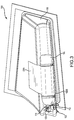
FIG. 3 , the gascylinder retention assembly 100 is shown in a side view. The chargedgas cylinder 102,container 104, flaps 106A-106B,structure 108, clamps 110A-110B, anddrawstring 112 are also shown. - The
container 104 covers substantially all of the body of the chargedgas cylinder 102. Thecontainer 104 also covers the bottom of chargedgas cylinder 102. The container also includes adrawstring 112. Thedrawstring 112 allows the chargedgas cylinder 102 to be secured in thecontainer 104 by drawing thedrawstring 112 closed around aneck 114 of the chargedgas cylinder 102. Thedrawstring 112 may be made of any strong woven material, such as nylon. - A
valve 120 may project out thecontainer 104 so that connections may be made to the chargedgas cylinder 102 without removal of the chargedgas cylinder 102 from thecontainer 104. Thecontainer 104 may be created specifically for the dimensions of the chargedgas cylinder 102, in order for the chargedgas cylinder 102 to fit snugly and securely within thecontainer 104. Movement of the chargedgas cylinder 102 within thecontainer 104 is not desirable. Further, excess fabric resulting from thecontainer 104 being too large for the chargedgas cylinder 102 may result in a poor fit in response to securing theclamps 110A-110B. Parts of thecontainer 104 may be woven together using a high strength thread, such as nylon thread, and using a secure technique, such as starting with a backstitch and ending with a backstitch. - While the charged
gas cylinder 102 and thecontainer 104 are shown inFIGS 1-3 as being in a horizontal configuration such that an axis along a length of thecontainer 104 is horizontal, any configuration may be used and the benefits described herein may be achieved. For example, the chargedgas cylinder 102 and thecontainer 104 may be in a vertical configuration such that the axis along the length of thecontainer 104 is vertical. The gascylinder retention assembly 100 still provides for stability of the chargedgas cylinder 102 within thecontainer 104 even in a vertical configuration. In various embodiments, the opening of thecontainer 104 is located above the closed bottom of the container in a vertical configuration. In such embodiments, the closed bottom of thecontainer 104 may support the weight of the chargedgas cylinder 102. In various embodiments the opening of thecontainer 104 may be located below the closed bottom of the container in the vertical configuration, with thedrawstring 112 drawn closed and secured providing the support for the weight of the chargedgas cylinder 102. - Referring now to
FIG. 4 ,container 104 is shown. As described herein, thecontainer 104 may be made of fabric such as cotton canvas, nylon, polyester, or a fabric made of aramid or para-aramid fibers. In various embodiments, a fabric with a high tensile strength is used. Thecontainer 104 may be created specifically for the dimensions of the chargedgas cylinder 102, in order for the chargedgas cylinder 102 to fit snugly and securely within thecontainer 104. Thedrawstring 112 may be loosened to allow for placement of the chargedgas cylinder 102 into thecontainer 104 and may be drawn closed around theneck 114 of the chargedgas cylinder 102 such that the chargedgas cylinder 102 is secure within thecontainer 104. The drawstring may be tied with a particular secure knot, or secured with aclasp 122. - The gas
cylinder retention assembly 100 may include a gas cylinder retention unit and thestructure 108. The gas cylinder retention unit may be a part of the gascylinder retention assembly 100 and includes thecontainer 104, theflaps 106A-106B, and thedrawstring 112. In various embodiments, the gas cylinder retention unit also includesclamps 110A-110B. - Referring now to
FIG. 5 , a method 500 for installing the gascylinder retention assembly 100 is shown. Inblock 502, flaps 106A-106B are attached to thestructure 108 of the aircraft. Theflaps 106A-106B are coupled to thecontainer 104 along the length of thecontainer 104 and extending radially from thecontainer 104. Theflaps 106A-106B are permanently attached to thestructure 108 using acontact adhesive 116. Theflaps 106A-106B are made of the same fabric as thecontainer 104. - In
block 504, the chargedgas cylinder 102 is placed inside thecontainer 104. In various embodiments, the chargedgas cylinder 102 provides air for an inflatable device in an evacuation situation. At this point, the chargedgas cylinder 102 is held against thestructure 108 by thecontainer 104 and theflaps 106A-106B. - In
block 506, thedrawstring 112 of thecontainer 104 is drawn closed around theneck 114 of the chargedgas cylinder 102. At this point, the chargedgas cylinder 102 is held against thestructure 108 such that it has limited movement in a Y-axis and is secured by the drawstring such that it has limited movement in an X-axis. - In
block 508, theclamps 110A-110B are wrapped around the outside of thecontainer 104. The clamps 110A-110B are attached to thestructure 108 of the airplane fuselage. - In
block 510, theclamps 110A-110B are tightened around thecontainer 104. The clamps 110A-110B provide further support for the charged gas cylinder to be held in place within the fuselage of the airplane. In various embodiments, theclamps 110A-110B are tightened according to a value calibrated specifically for the chargedgas cylinder 102 and thecontainer 104. - Benefits, other advantages, and solutions to problems have been described herein with regard to specific embodiments. Furthermore, the connecting lines shown in the various figures contained herein are intended to represent exemplary functional relationships and/or physical couplings between the various elements. It should be noted that many alternative or additional functional relationships or physical connections may be present in a practical system. However, the benefits, advantages, solutions to problems, and any elements that may cause any benefit, advantage, or solution to occur or become more pronounced are not to be construed as critical, required, or essential features or elements of the disclosure. The scope of the disclosure is accordingly to be limited by nothing other than the appended claims, in which reference to an element in the singular is not intended to mean "one and only one" unless explicitly so stated, but rather "one or more." Moreover, where a phrase similar to "at least one of A, B, or C" is used in the claims, it is intended that the phrase be interpreted to mean that A alone may be present in an embodiment, B alone may be present in an embodiment, C alone may be present in an embodiment, or that any combination of the elements A, B and C may be present in a single embodiment; for example, A and B, A and C, B and C, or A and B and C. Different cross-hatching is used throughout the figures to denote different parts but not necessarily to denote the same or different materials.
- Systems, methods and apparatus are provided herein. In the detailed description herein, references to "one embodiment", "an embodiment", "an example embodiment", etc., indicate that the embodiment described may include a particular feature, structure, or characteristic, but every embodiment may not necessarily include the particular feature, structure, or characteristic. Moreover, such phrases are not necessarily referring to the same embodiment. Further, when a particular feature, structure, or characteristic is described in connection with an embodiment, it is submitted that it is within the knowledge of one skilled in the art to affect such feature, structure, or characteristic in connection with other embodiments whether or not explicitly described. After reading the description, it will be apparent to one skilled in the relevant art(s) how to implement the disclosure in alternative embodiments.
- Furthermore, no element, component, or method step in the present disclosure is intended to be dedicated to the public regardless of whether the element, component, or method step is explicitly recited in the claims. No claim element herein is to be construed under the provisions of 35 U.S.C. 112, sixth paragraph, unless the element is expressly recited using the phrase "means for." As used herein, the terms "comprises", "comprising", or any other variation thereof, are intended to cover a non-exclusive inclusion, such that a process, method, article, or apparatus that comprises a list of elements does not include only those elements but may include other elements not expressly listed or inherent to such process, method, article, or apparatus.
Claims (15)
- A retention assembly (100) for securing a gas cylinder (102) to a body of an aircraft, comprising:a container (104) having an opening and configured to cover the gas cylinder (102);a plurality of flaps (106A, 106B) coupled to the container (104) and configured to be attached to the body of the aircraft using a contact adhesive (116); anda drawstring (112) disposed around the opening of the container (104) and configured to provide a closure of the container around a neck (114) of the gas cylinder (102) inside the container (104).
- The retention assembly of claim 1, wherein the container (104) is made of a fabric, and preferably the plurality of flaps (106A, 106B) are made of the fabric.
- The retention assembly of claim 1 or 2, wherein the retention assembly is further secured to the body of the aircraft by a clamp (110A, 110B) attached to the body of the aircraft, the at least one clamp (110A, 110B) wrapping around an exterior of the container (104).
- The retention assembly of any preceding claim, wherein the plurality of flaps (106A, 106B) are permanently attached to the body of the aircraft by the contact adhesive (116).
- A gas cylinder retention assembly (100) comprising:a structure (108) coupled to a body of an aircraft;a container (104) made of a fabric having an opening and configured to cover a gas cylinder (102);a plurality of flaps (106A, 106B) coupled to the container (104) and configured to be attached to the structure (108) using a contact adhesive (116); anda drawstring (112) disposed around the opening of the container (104) and configured to provide a closure of the container (104) around a neck (114) of the gas cylinder (102) inside the container (104).
- The gas cylinder retention assembly (100) of claim 5, wherein the plurality of flaps (106A, 106B) are made of the same fabric as the container (104).
- The gas cylinder retention assembly (100) of claim 5 or 6, wherein the container (104) is additionally secured to the structure (108) by at least one clamp (110A, 110B) attached to the structure (108), the at least one clamp (110A, 110B) wrapping around an exterior of the container (104).
- The gas cylinder retention assembly (100) of claim 5, 6 or 7, wherein the plurality of flaps (106A, 106B) are permanently attached to the structure (108) by the contact adhesive (116).
- The retention unit of any of claims 1 to 4 or the gas cylinder retention assembly (100) of any of claims 5 to 8, wherein each the plurality of flaps (106A, 106B) are disposed along a length of the container (104) and extend radially from the container (104).
- The retention unit of any of claims 1 to 4 or 9 or the gas cylinder retention assembly (100) of any of claims 5 to 9, wherein a valve (120) of the gas cylinder (102) extends out of the opening of the container (104).
- The retention unit of any of claims 1 to 4, 9 or 10 or the gas cylinder retention assembly (100) of any of claims 5 to 10, wherein the gas cylinder (102) is configured to provide air for an evacuation system.
- A method for installing a gas cylinder retention assembly (100) to a body of an aircraft, comprising:attaching, to the body of the aircraft using a contact adhesive (116), a plurality of flaps (106A, 106B) coupled to a container (104) having an opening;placing a gas cylinder (102) inside the container (104) through the opening; anddrawing closed a drawstring (112) disposed around the opening of the container (104), the drawstring (112) providing a closure of the container (104) around a neck (114) of the gas cylinder (102) inside the container (104).
- The method of claim 12, wherein the container (104) is made of a fabric, and preferably the plurality of flaps (106A, 106B) are made of the fabric.
- The method of claim 12 or 13, further comprising:wrapping a clamp (110A, 110B) attached to the body of the aircraft around an exterior of the container (104); andtightening the clamp (110A, 110B) such that the container (104) and the gas cylinder (102) within are securely held.
- The method of any of claims 12 to 14, wherein the plurality of flaps (106A, 106B) are permanently attached to the body of the aircraft using the contact adhesive (116).
Applications Claiming Priority (1)
| Application Number | Priority Date | Filing Date | Title |
|---|---|---|---|
| US15/132,787 US9790004B1 (en) | 2016-04-19 | 2016-04-19 | Retention system for gas cylinder of evacuation system |
Publications (2)
| Publication Number | Publication Date |
|---|---|
| EP3235733A1 true EP3235733A1 (en) | 2017-10-25 |
| EP3235733B1 EP3235733B1 (en) | 2018-12-12 |
Family
ID=58410140
Family Applications (1)
| Application Number | Title | Priority Date | Filing Date |
|---|---|---|---|
| EP17162321.8A Active EP3235733B1 (en) | 2016-04-19 | 2017-03-22 | Retention system for gas cylinder of evacuation system |
Country Status (3)
| Country | Link |
|---|---|
| US (1) | US9790004B1 (en) |
| EP (1) | EP3235733B1 (en) |
| BR (1) | BR102017004850B1 (en) |
Citations (5)
| Publication number | Priority date | Publication date | Assignee | Title |
|---|---|---|---|---|
| US2982105A (en) * | 1958-12-10 | 1961-05-02 | Sub Aqua Co Inc | Vest pack for tanks of underwater breathing apparatus |
| US5259372A (en) * | 1991-06-24 | 1993-11-09 | Gross Betty J | Oxygen cylinder carrier apparatus particularly for stretchers |
| US20040129305A1 (en) * | 2002-01-04 | 2004-07-08 | Hamilton Roger H | Oxygen bottle carrier appliance |
| US20110214276A1 (en) * | 2010-03-08 | 2011-09-08 | Sydney Noel Smith | Oxygen Cylinder Support for Use in Aircraft |
| US20130256571A1 (en) * | 2012-04-03 | 2013-10-03 | Joseph Marvin Cancel | Locking devices for valves and other equipment |
Family Cites Families (25)
| Publication number | Priority date | Publication date | Assignee | Title |
|---|---|---|---|---|
| US3753543A (en) * | 1971-11-19 | 1973-08-21 | Burrell Bros Inc | Bracket for gas containers |
| US3910532A (en) | 1974-04-25 | 1975-10-07 | Garrett Corp | Inflatable deployment system and method |
| US4055286A (en) * | 1975-12-22 | 1977-10-25 | Schmid Charles F | Portable mount for radios in motor vehicles |
| US4109692A (en) * | 1977-06-30 | 1978-08-29 | Brown Roland H | Encapsulating device for gas cylinder |
| US4143800A (en) * | 1978-03-10 | 1979-03-13 | Diversified Plastics Products Inc. | Litter box |
| USD267227S (en) * | 1980-07-28 | 1982-12-14 | Ziamatic Corporation | Support bracket for a gas cylinder |
| US4375877A (en) | 1980-12-31 | 1983-03-08 | The Boeing Company | Escape slide stowage and deployment system |
| US4451016A (en) | 1982-04-08 | 1984-05-29 | The B. F. Goodrich Company | Auxiliary flotation system |
| GB2164009B (en) | 1984-09-06 | 1988-02-10 | Fpt Industries | Flotation devices for aircraft undercarriages |
| US5511846A (en) * | 1993-09-23 | 1996-04-30 | Fuller Specialty Co., Inc. | Rugged scuba tank carrier |
| US5887437A (en) * | 1997-09-30 | 1999-03-30 | Beekley Corporation | Self-adhering cold pack |
| CA2243917A1 (en) * | 1998-07-23 | 2000-01-23 | Melvin Sheldon Mogil | Insulated bottle structure |
| US6220557B1 (en) * | 1999-09-28 | 2001-04-24 | Michael P. Ziaylek | Mounting bracket means for detachably supporting a generally cylindrically-shaped member upon a wall surface |
| CA2348139C (en) * | 2000-05-18 | 2009-04-07 | Ian Swan | Safety pouch for high pressure gas cylinders |
| US7198512B1 (en) * | 2003-10-27 | 2007-04-03 | Swiatek John A | Power distribution for luggage |
| GB2414066B (en) * | 2004-04-06 | 2007-01-10 | Glen Day | Securing & moving compressed gas cylinders |
| US20050275233A1 (en) * | 2004-06-15 | 2005-12-15 | Lisa Leighton | Ergonomic propane tank carrier and stabilizer |
| DE602005026155D1 (en) * | 2004-11-10 | 2011-03-10 | Ferno Washington | PORTABLE HOLDER FOR AN OXYGEN BOTTLE |
| US7753589B2 (en) * | 2006-08-28 | 2010-07-13 | Neil Palt | Encapsulating bag for pressurized cylinders to reduce particulate contamination for clean room use |
| US20080073355A1 (en) * | 2006-09-21 | 2008-03-27 | Saleem Akbar | Transportation bag for a tank or cylinder of gas or liquid in a vehicle |
| US8336577B2 (en) | 2008-04-23 | 2012-12-25 | Praxair Technology, Inc. | Pressurized gas containing system |
| GB2489051A (en) | 2011-03-18 | 2012-09-19 | Draeger Safety Uk Ltd | Breathing apparatus with two or more gas cylinders |
| US9205782B2 (en) * | 2013-03-15 | 2015-12-08 | John Byham | Bag for transporting gas cylinder |
| US9321404B1 (en) * | 2014-11-17 | 2016-04-26 | Clifford F. Mellenthin | Transportation system for tanks of compressed gas |
| US10077116B2 (en) * | 2015-03-19 | 2018-09-18 | Goodrich Corporation | Compressed gas tank assembly |
-
2016
- 2016-04-19 US US15/132,787 patent/US9790004B1/en active Active
-
2017
- 2017-03-10 BR BR102017004850-0A patent/BR102017004850B1/en active IP Right Grant
- 2017-03-22 EP EP17162321.8A patent/EP3235733B1/en active Active
Patent Citations (5)
| Publication number | Priority date | Publication date | Assignee | Title |
|---|---|---|---|---|
| US2982105A (en) * | 1958-12-10 | 1961-05-02 | Sub Aqua Co Inc | Vest pack for tanks of underwater breathing apparatus |
| US5259372A (en) * | 1991-06-24 | 1993-11-09 | Gross Betty J | Oxygen cylinder carrier apparatus particularly for stretchers |
| US20040129305A1 (en) * | 2002-01-04 | 2004-07-08 | Hamilton Roger H | Oxygen bottle carrier appliance |
| US20110214276A1 (en) * | 2010-03-08 | 2011-09-08 | Sydney Noel Smith | Oxygen Cylinder Support for Use in Aircraft |
| US20130256571A1 (en) * | 2012-04-03 | 2013-10-03 | Joseph Marvin Cancel | Locking devices for valves and other equipment |
Also Published As
| Publication number | Publication date |
|---|---|
| US9790004B1 (en) | 2017-10-17 |
| US20170297777A1 (en) | 2017-10-19 |
| BR102017004850A2 (en) | 2017-10-24 |
| BR102017004850B1 (en) | 2023-04-11 |
| EP3235733B1 (en) | 2018-12-12 |
Similar Documents
| Publication | Publication Date | Title |
|---|---|---|
| US8262023B2 (en) | Aircraft frame element connected to an air-conditioning system | |
| US10710733B2 (en) | Evacuation slide with aspirator retention strap | |
| US20210364187A1 (en) | Cover Accessory Apparatus | |
| EP3073173A1 (en) | Compressed gas tank assembly | |
| US20170320583A1 (en) | Systems and methods for retaining removable panel when deploying evacuation system | |
| US10703495B2 (en) | Secondary release arrangement for evacuation slide systems | |
| US20220388671A1 (en) | Systems and methods for soft cover attachment | |
| US11299281B2 (en) | Parachute assemblies with elastomeric inserts | |
| US9050691B2 (en) | Sleeve and rod support for fuel bladder | |
| US9790004B1 (en) | Retention system for gas cylinder of evacuation system | |
| US10618674B2 (en) | Lightweight portable vehicle cover | |
| US6382564B1 (en) | Flexible linkage system for environmentally sealed parachutes and other safety devices | |
| US12559261B2 (en) | Bracket fixture for space habitat | |
| US20210094693A1 (en) | Evacuation slide and method of forming evacuation slide having integral cable channel | |
| US20120102719A1 (en) | Attachment interface device for attaching mobile equipment to an aircraft structure | |
| US9774176B1 (en) | Method and apparatus for protection of wiring free ends and connectors | |
| US12319439B2 (en) | Method and apparatus for covering an aircraft engine | |
| JP2023064065A (en) | Suspension line assembly for parachute assembly, parachute assembly, and method of making parachute assembly | |
| US20180016093A1 (en) | Cargo container closure systems | |
| US9017789B2 (en) | Insulation assemblies for engine housings and associated methods of use and manufacture | |
| US10072769B2 (en) | Charged cylinder valve retention arrangement |
Legal Events
| Date | Code | Title | Description |
|---|---|---|---|
| PUAI | Public reference made under article 153(3) epc to a published international application that has entered the european phase |
Free format text: ORIGINAL CODE: 0009012 |
|
| STAA | Information on the status of an ep patent application or granted ep patent |
Free format text: STATUS: THE APPLICATION HAS BEEN PUBLISHED |
|
| AK | Designated contracting states |
Kind code of ref document: A1 Designated state(s): AL AT BE BG CH CY CZ DE DK EE ES FI FR GB GR HR HU IE IS IT LI LT LU LV MC MK MT NL NO PL PT RO RS SE SI SK SM TR |
|
| AX | Request for extension of the european patent |
Extension state: BA ME |
|
| STAA | Information on the status of an ep patent application or granted ep patent |
Free format text: STATUS: REQUEST FOR EXAMINATION WAS MADE |
|
| 17P | Request for examination filed |
Effective date: 20180424 |
|
| RBV | Designated contracting states (corrected) |
Designated state(s): AL AT BE BG CH CY CZ DE DK EE ES FI FR GB GR HR HU IE IS IT LI LT LU LV MC MK MT NL NO PL PT RO RS SE SI SK SM TR |
|
| GRAP | Despatch of communication of intention to grant a patent |
Free format text: ORIGINAL CODE: EPIDOSNIGR1 |
|
| STAA | Information on the status of an ep patent application or granted ep patent |
Free format text: STATUS: GRANT OF PATENT IS INTENDED |
|
| RIC1 | Information provided on ipc code assigned before grant |
Ipc: B64D 25/14 20060101AFI20180524BHEP |
|
| INTG | Intention to grant announced |
Effective date: 20180626 |
|
| GRAS | Grant fee paid |
Free format text: ORIGINAL CODE: EPIDOSNIGR3 |
|
| GRAA | (expected) grant |
Free format text: ORIGINAL CODE: 0009210 |
|
| STAA | Information on the status of an ep patent application or granted ep patent |
Free format text: STATUS: THE PATENT HAS BEEN GRANTED |
|
| AK | Designated contracting states |
Kind code of ref document: B1 Designated state(s): AL AT BE BG CH CY CZ DE DK EE ES FI FR GB GR HR HU IE IS IT LI LT LU LV MC MK MT NL NO PL PT RO RS SE SI SK SM TR |
|
| REG | Reference to a national code |
Ref country code: GB Ref legal event code: FG4D |
|
| REG | Reference to a national code |
Ref country code: CH Ref legal event code: EP |
|
| REG | Reference to a national code |
Ref country code: AT Ref legal event code: REF Ref document number: 1075649 Country of ref document: AT Kind code of ref document: T Effective date: 20181215 |
|
| REG | Reference to a national code |
Ref country code: DE Ref legal event code: R096 Ref document number: 602017001275 Country of ref document: DE |
|
| REG | Reference to a national code |
Ref country code: IE Ref legal event code: FG4D |
|
| REG | Reference to a national code |
Ref country code: NL Ref legal event code: MP Effective date: 20181212 |
|
| REG | Reference to a national code |
Ref country code: LT Ref legal event code: MG4D |
|
| PG25 | Lapsed in a contracting state [announced via postgrant information from national office to epo] |
Ref country code: ES Free format text: LAPSE BECAUSE OF FAILURE TO SUBMIT A TRANSLATION OF THE DESCRIPTION OR TO PAY THE FEE WITHIN THE PRESCRIBED TIME-LIMIT Effective date: 20181212 Ref country code: NO Free format text: LAPSE BECAUSE OF FAILURE TO SUBMIT A TRANSLATION OF THE DESCRIPTION OR TO PAY THE FEE WITHIN THE PRESCRIBED TIME-LIMIT Effective date: 20190312 Ref country code: LT Free format text: LAPSE BECAUSE OF FAILURE TO SUBMIT A TRANSLATION OF THE DESCRIPTION OR TO PAY THE FEE WITHIN THE PRESCRIBED TIME-LIMIT Effective date: 20181212 Ref country code: HR Free format text: LAPSE BECAUSE OF FAILURE TO SUBMIT A TRANSLATION OF THE DESCRIPTION OR TO PAY THE FEE WITHIN THE PRESCRIBED TIME-LIMIT Effective date: 20181212 Ref country code: BG Free format text: LAPSE BECAUSE OF FAILURE TO SUBMIT A TRANSLATION OF THE DESCRIPTION OR TO PAY THE FEE WITHIN THE PRESCRIBED TIME-LIMIT Effective date: 20190312 Ref country code: FI Free format text: LAPSE BECAUSE OF FAILURE TO SUBMIT A TRANSLATION OF THE DESCRIPTION OR TO PAY THE FEE WITHIN THE PRESCRIBED TIME-LIMIT Effective date: 20181212 Ref country code: LV Free format text: LAPSE BECAUSE OF FAILURE TO SUBMIT A TRANSLATION OF THE DESCRIPTION OR TO PAY THE FEE WITHIN THE PRESCRIBED TIME-LIMIT Effective date: 20181212 |
|
| REG | Reference to a national code |
Ref country code: AT Ref legal event code: MK05 Ref document number: 1075649 Country of ref document: AT Kind code of ref document: T Effective date: 20181212 |
|
| PG25 | Lapsed in a contracting state [announced via postgrant information from national office to epo] |
Ref country code: AL Free format text: LAPSE BECAUSE OF FAILURE TO SUBMIT A TRANSLATION OF THE DESCRIPTION OR TO PAY THE FEE WITHIN THE PRESCRIBED TIME-LIMIT Effective date: 20181212 Ref country code: SE Free format text: LAPSE BECAUSE OF FAILURE TO SUBMIT A TRANSLATION OF THE DESCRIPTION OR TO PAY THE FEE WITHIN THE PRESCRIBED TIME-LIMIT Effective date: 20181212 Ref country code: RS Free format text: LAPSE BECAUSE OF FAILURE TO SUBMIT A TRANSLATION OF THE DESCRIPTION OR TO PAY THE FEE WITHIN THE PRESCRIBED TIME-LIMIT Effective date: 20181212 Ref country code: GR Free format text: LAPSE BECAUSE OF FAILURE TO SUBMIT A TRANSLATION OF THE DESCRIPTION OR TO PAY THE FEE WITHIN THE PRESCRIBED TIME-LIMIT Effective date: 20190313 |
|
| PG25 | Lapsed in a contracting state [announced via postgrant information from national office to epo] |
Ref country code: NL Free format text: LAPSE BECAUSE OF FAILURE TO SUBMIT A TRANSLATION OF THE DESCRIPTION OR TO PAY THE FEE WITHIN THE PRESCRIBED TIME-LIMIT Effective date: 20181212 |
|
| PG25 | Lapsed in a contracting state [announced via postgrant information from national office to epo] |
Ref country code: CZ Free format text: LAPSE BECAUSE OF FAILURE TO SUBMIT A TRANSLATION OF THE DESCRIPTION OR TO PAY THE FEE WITHIN THE PRESCRIBED TIME-LIMIT Effective date: 20181212 Ref country code: IT Free format text: LAPSE BECAUSE OF FAILURE TO SUBMIT A TRANSLATION OF THE DESCRIPTION OR TO PAY THE FEE WITHIN THE PRESCRIBED TIME-LIMIT Effective date: 20181212 Ref country code: PL Free format text: LAPSE BECAUSE OF FAILURE TO SUBMIT A TRANSLATION OF THE DESCRIPTION OR TO PAY THE FEE WITHIN THE PRESCRIBED TIME-LIMIT Effective date: 20181212 Ref country code: PT Free format text: LAPSE BECAUSE OF FAILURE TO SUBMIT A TRANSLATION OF THE DESCRIPTION OR TO PAY THE FEE WITHIN THE PRESCRIBED TIME-LIMIT Effective date: 20190412 |
|
| PG25 | Lapsed in a contracting state [announced via postgrant information from national office to epo] |
Ref country code: EE Free format text: LAPSE BECAUSE OF FAILURE TO SUBMIT A TRANSLATION OF THE DESCRIPTION OR TO PAY THE FEE WITHIN THE PRESCRIBED TIME-LIMIT Effective date: 20181212 Ref country code: SM Free format text: LAPSE BECAUSE OF FAILURE TO SUBMIT A TRANSLATION OF THE DESCRIPTION OR TO PAY THE FEE WITHIN THE PRESCRIBED TIME-LIMIT Effective date: 20181212 Ref country code: IS Free format text: LAPSE BECAUSE OF FAILURE TO SUBMIT A TRANSLATION OF THE DESCRIPTION OR TO PAY THE FEE WITHIN THE PRESCRIBED TIME-LIMIT Effective date: 20190412 Ref country code: RO Free format text: LAPSE BECAUSE OF FAILURE TO SUBMIT A TRANSLATION OF THE DESCRIPTION OR TO PAY THE FEE WITHIN THE PRESCRIBED TIME-LIMIT Effective date: 20181212 Ref country code: SK Free format text: LAPSE BECAUSE OF FAILURE TO SUBMIT A TRANSLATION OF THE DESCRIPTION OR TO PAY THE FEE WITHIN THE PRESCRIBED TIME-LIMIT Effective date: 20181212 |
|
| REG | Reference to a national code |
Ref country code: DE Ref legal event code: R097 Ref document number: 602017001275 Country of ref document: DE |
|
| PLBE | No opposition filed within time limit |
Free format text: ORIGINAL CODE: 0009261 |
|
| STAA | Information on the status of an ep patent application or granted ep patent |
Free format text: STATUS: NO OPPOSITION FILED WITHIN TIME LIMIT |
|
| PG25 | Lapsed in a contracting state [announced via postgrant information from national office to epo] |
Ref country code: DK Free format text: LAPSE BECAUSE OF FAILURE TO SUBMIT A TRANSLATION OF THE DESCRIPTION OR TO PAY THE FEE WITHIN THE PRESCRIBED TIME-LIMIT Effective date: 20181212 Ref country code: AT Free format text: LAPSE BECAUSE OF FAILURE TO SUBMIT A TRANSLATION OF THE DESCRIPTION OR TO PAY THE FEE WITHIN THE PRESCRIBED TIME-LIMIT Effective date: 20181212 Ref country code: MC Free format text: LAPSE BECAUSE OF FAILURE TO SUBMIT A TRANSLATION OF THE DESCRIPTION OR TO PAY THE FEE WITHIN THE PRESCRIBED TIME-LIMIT Effective date: 20181212 Ref country code: SI Free format text: LAPSE BECAUSE OF FAILURE TO SUBMIT A TRANSLATION OF THE DESCRIPTION OR TO PAY THE FEE WITHIN THE PRESCRIBED TIME-LIMIT Effective date: 20181212 |
|
| 26N | No opposition filed |
Effective date: 20190913 |
|
| PG25 | Lapsed in a contracting state [announced via postgrant information from national office to epo] |
Ref country code: LU Free format text: LAPSE BECAUSE OF NON-PAYMENT OF DUE FEES Effective date: 20190322 |
|
| REG | Reference to a national code |
Ref country code: BE Ref legal event code: MM Effective date: 20190331 |
|
| PG25 | Lapsed in a contracting state [announced via postgrant information from national office to epo] |
Ref country code: IE Free format text: LAPSE BECAUSE OF NON-PAYMENT OF DUE FEES Effective date: 20190322 |
|
| PG25 | Lapsed in a contracting state [announced via postgrant information from national office to epo] |
Ref country code: BE Free format text: LAPSE BECAUSE OF NON-PAYMENT OF DUE FEES Effective date: 20190331 |
|
| PG25 | Lapsed in a contracting state [announced via postgrant information from national office to epo] |
Ref country code: TR Free format text: LAPSE BECAUSE OF FAILURE TO SUBMIT A TRANSLATION OF THE DESCRIPTION OR TO PAY THE FEE WITHIN THE PRESCRIBED TIME-LIMIT Effective date: 20181212 |
|
| PG25 | Lapsed in a contracting state [announced via postgrant information from national office to epo] |
Ref country code: MT Free format text: LAPSE BECAUSE OF NON-PAYMENT OF DUE FEES Effective date: 20190322 |
|
| REG | Reference to a national code |
Ref country code: CH Ref legal event code: PL |
|
| PG25 | Lapsed in a contracting state [announced via postgrant information from national office to epo] |
Ref country code: LI Free format text: LAPSE BECAUSE OF NON-PAYMENT OF DUE FEES Effective date: 20200331 Ref country code: CH Free format text: LAPSE BECAUSE OF NON-PAYMENT OF DUE FEES Effective date: 20200331 |
|
| PG25 | Lapsed in a contracting state [announced via postgrant information from national office to epo] |
Ref country code: CY Free format text: LAPSE BECAUSE OF FAILURE TO SUBMIT A TRANSLATION OF THE DESCRIPTION OR TO PAY THE FEE WITHIN THE PRESCRIBED TIME-LIMIT Effective date: 20181212 |
|
| PG25 | Lapsed in a contracting state [announced via postgrant information from national office to epo] |
Ref country code: HU Free format text: LAPSE BECAUSE OF FAILURE TO SUBMIT A TRANSLATION OF THE DESCRIPTION OR TO PAY THE FEE WITHIN THE PRESCRIBED TIME-LIMIT; INVALID AB INITIO Effective date: 20170322 |
|
| GBPC | Gb: european patent ceased through non-payment of renewal fee |
Effective date: 20210322 |
|
| PG25 | Lapsed in a contracting state [announced via postgrant information from national office to epo] |
Ref country code: GB Free format text: LAPSE BECAUSE OF NON-PAYMENT OF DUE FEES Effective date: 20210322 |
|
| PG25 | Lapsed in a contracting state [announced via postgrant information from national office to epo] |
Ref country code: MK Free format text: LAPSE BECAUSE OF FAILURE TO SUBMIT A TRANSLATION OF THE DESCRIPTION OR TO PAY THE FEE WITHIN THE PRESCRIBED TIME-LIMIT Effective date: 20181212 |
|
| REG | Reference to a national code |
Ref country code: FR Ref legal event code: PLFP Year of fee payment: 7 |
|
| P01 | Opt-out of the competence of the unified patent court (upc) registered |
Effective date: 20230522 |
|
| PGFP | Annual fee paid to national office [announced via postgrant information from national office to epo] |
Ref country code: DE Payment date: 20260219 Year of fee payment: 10 |
|
| PGFP | Annual fee paid to national office [announced via postgrant information from national office to epo] |
Ref country code: FR Payment date: 20260219 Year of fee payment: 10 |