EP3235707B1 - Electric power steering apparatus - Google Patents
Electric power steering apparatus Download PDFInfo
- Publication number
- EP3235707B1 EP3235707B1 EP17165121.9A EP17165121A EP3235707B1 EP 3235707 B1 EP3235707 B1 EP 3235707B1 EP 17165121 A EP17165121 A EP 17165121A EP 3235707 B1 EP3235707 B1 EP 3235707B1
- Authority
- EP
- European Patent Office
- Prior art keywords
- torque
- steering
- integral
- section
- value
- Prior art date
- Legal status (The legal status is an assumption and is not a legal conclusion. Google has not performed a legal analysis and makes no representation as to the accuracy of the status listed.)
- Active
Links
- 238000005562 fading Methods 0.000 claims description 3
- 101100208381 Caenorhabditis elegans tth-1 gene Proteins 0.000 description 26
- 101100096895 Mus musculus Sult2a2 gene Proteins 0.000 description 19
- 230000010354 integration Effects 0.000 description 14
- 230000008859 change Effects 0.000 description 8
- 238000010586 diagram Methods 0.000 description 8
- 230000001133 acceleration Effects 0.000 description 6
- 230000007246 mechanism Effects 0.000 description 5
- 230000006641 stabilisation Effects 0.000 description 5
- 238000011105 stabilization Methods 0.000 description 5
- 230000009467 reduction Effects 0.000 description 3
- 238000006243 chemical reaction Methods 0.000 description 2
- 230000008030 elimination Effects 0.000 description 2
- 238000003379 elimination reaction Methods 0.000 description 2
- 238000000034 method Methods 0.000 description 2
- 230000008569 process Effects 0.000 description 2
- 230000009471 action Effects 0.000 description 1
- 230000008901 benefit Effects 0.000 description 1
- 230000005540 biological transmission Effects 0.000 description 1
- 238000001514 detection method Methods 0.000 description 1
- 238000006073 displacement reaction Methods 0.000 description 1
- 230000000694 effects Effects 0.000 description 1
- 230000003993 interaction Effects 0.000 description 1
- 230000007935 neutral effect Effects 0.000 description 1
- 230000010363 phase shift Effects 0.000 description 1
- 239000004575 stone Substances 0.000 description 1
Images


Classifications
-
- B—PERFORMING OPERATIONS; TRANSPORTING
- B62—LAND VEHICLES FOR TRAVELLING OTHERWISE THAN ON RAILS
- B62D—MOTOR VEHICLES; TRAILERS
- B62D1/00—Steering controls, i.e. means for initiating a change of direction of the vehicle
- B62D1/24—Steering controls, i.e. means for initiating a change of direction of the vehicle not vehicle-mounted
- B62D1/28—Steering controls, i.e. means for initiating a change of direction of the vehicle not vehicle-mounted non-mechanical, e.g. following a line or other known markers
- B62D1/286—Systems for interrupting non-mechanical steering due to driver intervention
-
- B—PERFORMING OPERATIONS; TRANSPORTING
- B62—LAND VEHICLES FOR TRAVELLING OTHERWISE THAN ON RAILS
- B62D—MOTOR VEHICLES; TRAILERS
- B62D5/00—Power-assisted or power-driven steering
- B62D5/04—Power-assisted or power-driven steering electrical, e.g. using an electric servo-motor connected to, or forming part of, the steering gear
- B62D5/0457—Power-assisted or power-driven steering electrical, e.g. using an electric servo-motor connected to, or forming part of, the steering gear characterised by control features of the drive means as such
- B62D5/046—Controlling the motor
- B62D5/0463—Controlling the motor calculating assisting torque from the motor based on driver input
-
- B—PERFORMING OPERATIONS; TRANSPORTING
- B62—LAND VEHICLES FOR TRAVELLING OTHERWISE THAN ON RAILS
- B62D—MOTOR VEHICLES; TRAILERS
- B62D6/00—Arrangements for automatically controlling steering depending on driving conditions sensed and responded to, e.g. control circuits
- B62D6/02—Arrangements for automatically controlling steering depending on driving conditions sensed and responded to, e.g. control circuits responsive only to vehicle speed
-
- B—PERFORMING OPERATIONS; TRANSPORTING
- B62—LAND VEHICLES FOR TRAVELLING OTHERWISE THAN ON RAILS
- B62D—MOTOR VEHICLES; TRAILERS
- B62D6/00—Arrangements for automatically controlling steering depending on driving conditions sensed and responded to, e.g. control circuits
- B62D6/08—Arrangements for automatically controlling steering depending on driving conditions sensed and responded to, e.g. control circuits responsive only to driver input torque
Definitions
- the present invention relates to an electric power steering apparatus that has functions of an automatic steering mode (a parking support mode) and a manual steering mode and provides a steering system of a vehicle with an assist force by means of a motor, and in particular to an electric power steering apparatus that improves performance of a switching judgment from the automatic steering mode to the manual steering mode.
- an automatic steering mode a parking support mode
- a manual steering mode a steering system of a vehicle with an assist force by means of a motor
- an electric power steering apparatus that improves performance of a switching judgment from the automatic steering mode to the manual steering mode.
- An electric power steering apparatus which provides a steering mechanism of a vehicle with a steering assist torque (assist force) by means of rotational torque of a motor applies driving force of the motor as the steering assist torque to a steering shaft or a rack shaft by means of a transmission mechanism such as gears or a belt through a reduction mechanism.
- EPS electric power steering
- Such a conventional electric power steering (EPS) apparatus performs a feedback control of a motor current.
- the feedback control adjusts a voltage supplied to the motor so that a difference between a steering assist command value (a current command value) and a detected motor current value becomes small, and the adjustment of the voltage supplied to the motor is generally performed by an adjustment of a duty of a PWM (Pulse Width Modulation) control.
- PWM Pulse Width Modulation
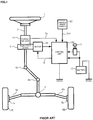
- a column shaft (a steering shaft) 2 connected to a steering handle (a steering wheel) 1 is connected to steered wheels 8L and 8R through reduction gears 3, universal joints 4a and 4b, a rack and pinion mechanism 5, and tie rods 6a and 6b, further via hub units 7a and 7b.
- the column shaft 2 is provided with a torque sensor 10 for detecting a steering torque of the steering wheel 1, and a motor 20 for assisting the steering force of the steering wheel 1 is connected to the column shaft 2 through the reduction gears 3.
- Electric power is supplied to a control unit (ECU) 100 for controlling the electric power steering apparatus from a battery 13, and an ignition key signal is inputted into the control unit 100 through an ignition key 11.
- the control unit 100 calculates a steering assist command value of an assist (steering assist) command based on the steering torque Th detected by the torque sensor 10 and a vehicle speed Vel detected by a vehicle speed sensor 12, and controls a current supplied to the motor 20 based on a current control value E obtained by performing compensation and so on with respect to the steering assist command value.
- control unit 100 is, for example, configured as shown in FIG.2 disclosed in Japanese Published Unexamined Patent Application No. 2002-369565 A .
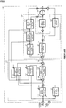
- the motor 20 that generates the steering assist torque of the electric power steering apparatus is driven by a motor driving section 21, the motor driving section 21 is controlled by the control unit 100 shown by a two-dot chain line, and the the steering torque Th from the torque sensor 10 and the vehicle speed Vel from the vehicle speed detecting system are inputted into the control unit 100.
- a voltage Vm between the motor terminals and a motor current value i are measured and outputted in the motor 20.
- the control unit 100 comprises a torque system control section 110 that performs the control by means of the steering torque Th and is shown by a broken line, and a motor system control section 120 that performs the control related to a drive of the motor 20 and is shown by a dashed line.
- the torque system control section 110 comprises an assist amount calculating section 111, a differential control section 112, a yaw-rate convergence control section 113, a robust stabilization compensating section 114, and a self aligning torque (SAT) estimation feedback section 115, and includes an adding section 116A and 116B and a subtracting section 116C.
- SAT self aligning torque
- the motor system control section 120 comprises a compensating section 121, a disturbance estimating section 122, a motor angular speed calculating section 123, a motor angular acceleration calculating section 124, and a motor characteristic compensating section 125, and includes an adding section 126A and 126B.
- the steering torque Th is inputted into the assist amount calculating section 111, the differential control section 112, the yaw-rate convergence control section 113 and the SAT estimation feedback section 115, which all input the vehicle speed Vel as a parameter.
- the assist amount calculating section 111 calculates an assist torque amount based on the steering torque Th.
- the yaw-rate convergence control section 113 inputs the steering torque Th and a motor angular speed ⁇ , and puts a brake on an action of the steering wheel whirling in order to improve the convergence of the vehicle yaw.
- the differential control section 112 improves the control responsibility near a neutral point of the steering wheel, and achieves smooth steering.
- the SAT estimation feedback section 115 inputs the steering torque Th, a signal made by adding an output from the differential control section 112 to an output from the assist amount calculating section 111 in the adding section 116A, the motor angular speed ⁇ calculated in the motor angular speed calculating section 123 and a motor angular acceleration ⁇ , estimates an SAT, performs signal processing of the estimated SAT by means of a feedback filter, and gives an appropriate road-surface information to the steering wheel as reaction force.
- a signal made in the adding section 116B by adding an output from the yaw-rate convergence control section 113 to a signal made in the adding section 116A by adding an output from the differential control section 112 to an output from the assist amount calculating section 111 is inputted as an assist amount AQ into the robust stabilization compensating section 114.
- the robust stabilization compensating section 114 is, for example, a compensating section shown in Japanese Published Unexamined Patent Application No. H8-290778 A , eliminates a resonance frequency peak of a resonator system comprising an inertial element and a spring element included by the detected torque, and compensates a phase shift of a resonance frequency to inhibit the responsibility and the stability of a control system.
- An assist amount Ia that is capable of transmitting the road-surface information to the steering wheel as reaction force is obtained by subtracting an output of the SAT estimation feedback section 115 from an output of the robust stabilization compensating section 114 in the subtracting section 116C.
- the motor angular speed calculating section 123 calculates the motor angular speed ⁇ based on the voltage Vm between the motor terminals and the motor current value i, and the motor angular speed ⁇ is inputted into the motor angular acceleration calculating section 124, the yaw-rate convergence control section 113 and the SAT estimation feedback section 115.
- the motor angular acceleration calculating section 124 calculates the motor angular acceleration ⁇ based on the inputted motor angular speed ⁇ , and the calculated motor angular acceleration ⁇ is inputted into the motor characteristic compensating section 125 and the SAT estimation feedback section 115.
- the assist amount Ia left by the subtraction of the output of the SAT estimation feedback section 115 from the output of the robust stabilization compensating section 114 is added to an output Ic of the motor characteristic compensating section 125 in the adding section 126A, and the adding signal is inputted as a current command value Ir into the compensating section 121 comprising a differential compensating section and so on.
- the disturbance estimating section 122 is such an apparatus as shown in Japanese Published Unexamined Patent Application No.
- H8-310417 A is capable of maintaining a motor control characteristic desired on an output standard of a control system based on the signal made by adding the output from the disturbance estimating section 122 to the current command value Ira that is a control target of a motor output and is compensated in the compensating section 121 and the motor current value i, and prevents the loss of the stability of the control system.
- vehicles provided with a parking support function parking assist
- switching an automatic steering mode and a manual steering mode recently appear.
- the vehicle provided with the parking support function sets a target steering angle based on data such as a camera (an image), a distance sensor and so on, and performs automatic control according to the target steering angle.
- the conventional electric power steering apparatus stops the automatic steering control when a driver steers a steering wheel in the automatic steering mode and the steering torque is judged to exceed a predetermined value set beforehand.
- the output of the torque sensor exceeds the predetermined value temporarily because of a noise of the torque sensor or an inertial torque of the steering wheel appearing in the case of a tire stepping on a pebble or automatic steering by the motor, and each time the automatic steering control is made stopped.
- the predetermined value is set to high in order to avoid such an inconvenience, not only does the interaction between the automatic steering mode and the manual steering mode give uncomfortable feeling to the driver, but also there is a possibility that the automatic steering control is not immediately stopped even if the driver steers the steering wheel in the automatic steering control.
- Patent Document 1 Japanese Patent No. 3845188 B2
- the apparatus disclosed in Patent Document 1 sets plural kinds of the predetermined values and changes a predetermined time corresponding to each predetermined value in an automatic steering apparatus for a vehicle that comprises a moving locus setting means for storing or calculating vehicle moving locus to a target position, an actuator (a motor) for steering a wheel, a steering torque detecting means (a torque sensor) for detecting a steering torque that a driver applies to a steering wheel, and an actuator control means for controlling the actuator drive based on the moving locus set by the moving locus setting means and at the same time stopping an actuator control based on the moving locus when the steering torque over the predetermined value set beforehand is detected for more than the predetermined time.
- a moving locus setting means for storing or calculating vehicle moving locus to a target position
- an actuator a motor
- a steering torque detecting means a torque sensor
- an actuator control means for controlling the actuator drive based on the moving locus set by the moving locus setting means and at the
- Patent Document 2 discloses a vehicle steering system according to the preamble of claim 1 which includes a steering actuator (M) that imparts a steering force to a steering mechanism of a vehicle; an automatic steering controller that performs an automatic steering control by controlling the steering actuator (M); a driving state detector that detects a driving state of the vehicle during the automatic steering control; a threshold value setting unit that variably sets a threshold value for permitting an intervention in the automatic steering control; and an automatic steering intervention unit that intervenes in the automatic steering control based on a threshold value set by the threshold value setting unit.
- M steering actuator
- M an automatic steering controller that performs an automatic steering control by controlling the steering actuator (M)
- a driving state detector that detects a driving state of the vehicle during the automatic steering control
- a threshold value setting unit that variably sets a threshold value for permitting an intervention in the automatic steering control
- an automatic steering intervention unit that intervenes in the automatic steering control based on a threshold value set by the threshold value setting unit.
- Patent Document 1 Japanese Patent No. 3845188 B2
- Patent Document 2 EP 1 864 889 A2
- Patent Document 1 stops the automatic steering control when the predetermined time corresponding to the steering torque of the driver passes. There are problems that it is complicated to set plural kinds of the predetermined values and change the predetermined time corresponding to each predetermined value, and a calculation load is large.
- the present invention has been developed in view of the above-described circumstances, and an object of the present invention is to provide an electric power steering apparatus that does not give uncomfortable feeling to the driver in the vehicle having functions of the automatic steering mode and the manual steering mode by detecting that the driver steers the steering wheel in the automatic steering mode by means of the steering torque from the torque sensor and switching to the manual steering mode when a capacity (an integrated value) corresponding to the occurring torque magnitude becomes over a predetermined value or over a predetermined value set finely.
- the present invention relates to an electric power steering apparatus in accordance with the appended claims.
- an electric power steering apparatus that calculates a motor current command value 1 based on a steering torque and a vehicle speed, drives a motor based on said motor current command value 1 so as to perform an assist control of a steering system, and has a function for switching an automatic steering mode and a manual steering mode
- the above-described object of the present invention is achieved by that comprising: a steering angle control section that calculates a motor current command value 2 to get an actual steering angle close to a target steering angle; a torque integral judging section that outputs a steering torque judging signal by integrating said steering torque, which is compared with a predetermined threshold; and a switching section that inputs said motor current command value 1 and said motor current command value 2, and is switched in accordance with a switching signal or said steering torque judging signal; wherein said torque integral judging section comprises a torque value comparing section that compares an absolute value of said steering torque with a torque threshold so as to output a
- an electric power steering apparatus that calculates a motor current command value 1 based on a steering torque and a vehicle speed, drives a motor based on said motor current command value 1 so as to perform an assist control of a steering system, and has a function for switching an automatic steering mode and a manual steering mode
- the above-described object of the present invention is achieved by that comprising: a steering angle control section that calculates a motor current command value 2 to get an actual steering angle close to a target steering angle; a torque integral judging section that outputs a steering torque judging signal by integrating said steering torque, which is compared with a predetermined threshold; and a switching section that inputs said motor current command value 1 and said motor current command value 2, and is switched in accordance with a switching signal or said steering torque judging signal; wherein said torque integral judging section comprises plural torque value comparing sections that compare an absolute value of said steering torque with plural torque thresholds so as to output each predetermined signal, plural integral calculating sections that integrate said each predetermined signal, and a switch judging
- the electric power steering apparatus of the present invention it is possible in the vehicle having the automatic steering mode (the parking support function) and the manual steering mode to shorten the time required for switching judgment as the steering torque is larger because of integrating the steering torque when the steering torque becomes over a predetermined torque threshold and moreover performing the switching control by comparing the magnitude of the integrated value with a predetermined integral threshold.
- the electric power steering apparatus does not give uncomfortable feeling to the driver especially in case of switching to the manual steering mode in the automatic steering mode because of performing the switching judgment not by passage of time but by the integrated value of the steering torque.
- an electric power steering apparatus that calculates a motor current command value 1 based on a steering torque and a vehicle speed, drives a motor based on said motor current command value 1 so as to perform an assist control of a steering system, and has a function for switching an automatic steering mode and a manual steering mode, comprising:
- said torque integral judging section comprises an LPF in a front stage of said torque value comparing section.
- said torque value comparing section includes a function for outputting said absolute value when said absolute value is equal to or larger than said torque threshold, and outputting 0 and at the same time outputting a past-value initializing signal to initialize said integral calculating section when said absolute value is smaller than said torque threshold.
- said switch judging section includes a function for outputting said steering torque judging signal when said integral value is equal to or larger than said integral threshold, and not outputting said steering torque judging signal when said integral value is smaller than said integral threshold.
- the electric power steering apparatus according to any one of the first to fourth paragraph, wherein said switching section is switched in accordance with said steering torque judging signal so as to switch to said manual steering mode when said absolute value is equal to or larger than said torque threshold and said integral value becomes equal to or larger than said integral threshold in said automatic steering mode.
- an electric power steering apparatus that calculates a motor current command value 1 based on a steering torque and a vehicle speed, drives a motor based on said motor current command value 1 so as to perform an assist control of a steering system, and has a function for switching an automatic steering mode and a manual steering mode, comprising:
- said torque integral judging section comprises an LPF in a front stage of said plural torque value comparing sections.
- said plural torque value comparing sections respectively include a function for outputting said absolute value when said absolute value is equal to or larger than a self-corresponding torque threshold, and outputting 0 and at the same time outputting a past-value initializing signal to initialize self-corresponding said integral calculating section when said absolute value is smaller than said self-corresponding torque threshold.
- said switch judging section includes a function for outputting said steering torque judging signal when said plural integral values are respectively equal to or larger than corresponding said plural integral thresholds, and not outputting said steering torque judging signal in any other case.
- the electric power steering apparatus according to any one of the sixth to ninth paragraph, wherein said switching section is switched in accordance with said steering torque judging signal so as to switch to said manual steering mode when said absolute value is equal to or larger than said self-corresponding torque threshold and said integral value becomes equal to or larger than said self-corresponding integral threshold in said automatic steering mode.
- the present invention in an electric power steering apparatus of a vehicle having functions of an automatic steering mode and a manual steering mode, detects that a driver steers a steering wheel in the automatic steering mode by means of a steering torque from a torque sensor, at the same time switches to the manual steering mode when a capacity (an integrated value) corresponding to the occurring torque magnitude becomes over a predetermined value, and does not give uncomfortable feeling to the driver in any situation.
- FIG.3 shows a configuration example (a first embodiment) of the present invention.
- a rotation angle sensor 151 such as a resolver and so on, for detecting a motor rotation angle ⁇ s is connected to a motor 150, and the motor 150 is driven and controlled through a vehicle-side ECU 130 and an electric power steering apparatus (EPS)-side ECU 140.
- EPS electric power steering apparatus
- the vehicle-side ECU 130 comprises a switching command section 131 that outputs a switching command SW of either an automatic steering mode or a manual steering mode based on a button, a switch and so on to show a driver's intention, and a target steering angle generating section 132 that generates a target steering angle ⁇ t based on a signal from a camera (an image), a distance sensor and so on. Further, an actual steering angle ⁇ r detected by a steering angle sensor 152 which a column shaft is provided with and a vehicle speed Vel from a vehicle speed sensor 153 are inputted through the vehicle-side ECU 130 into a steering angle control section 200 within the EPS-side ECU 140.
- An output from the steering angle sensor 152 may be an estimated value of a steering angle estimated by the column shaft (including an intermediate shaft and a pinion shaft), a displacement of a rack of a rack and pinion, a wheel speed and so on. Further, it is also possible to receive the vehicle speed Vel from a CAN and so on.
- the switching command section 131 outputs the switching command SW based on a signal for identifying whether to enter the automatic steering mode, for example a signal of a vehicle state by means of the button or the switch which a dashboard or a steering wheel area is provided with to show the driver's intention, a parking mode set in a shift and so on, and inputs the switching command SW into a switching section 142 within the EPS-side ECU 140.
- the target steering angle generating section 132 generates the target steering angle ⁇ t based on data from the camera (the image), the distance sensor and so on by a well-known manner, and inputs the generated target steering angle ⁇ t into the steering angle control section 200 within the EPS-side ECU 140.
- the EPS-side ECU 140 comprises a torque control section 141 that outputs a motor current command value Itref that is calculated based on a steering torque Th from a torque sensor 154 and a motor angular speed ⁇ , the steering angle control section 200 that calculates and outputs a motor current command value Imref for an automatic control of a steering angle based on the target steering angle ⁇ t, the actual steering angle ⁇ r, the vehicle speed Vel, the steering torque Th and the motor angular speed ⁇ , the switching section 142 that switches the motor current command value Itref and the motor current command value Imref by means of the switching command SW from the switching command section 131 or a steering torque judging signal TD and outputs a motor current command value Iref, a current control/driving section 143 that drives and controls the motor 150 based on the motor current command value Iref (Itref or Imref) from the switching section 142, a motor angular speed calculating section 144 that calculates the motor angular speed ⁇
- the switching section 142 switches a torque control mode (the manual steering mode) by the torque control section 141 and the automatic steering mode by the steering angle control section 200 based on the switching command SW from the switching command section 131 within the vehicle-side ECU 130 or the steering torque judging signal TD from the torque integral judging section 300, outputs the motor current command value Itref as the motor current command value Iref in the manual steering mode, and outputs the motor current command value Imref as the motor current command value Iref in the automatic steering mode.
- the current control/driving section 143 comprises a PI current control section, a PWM control section, an inverter and so on.
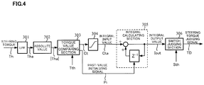
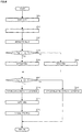
- the torque integral judging section 300 is configured as shown in FIG.4 , and comprises an LPF (Low-Pass Filter) 301 for eliminating a noise of the steering torque Th, an absolute value section 302 that calculates an absolute value of a steering torque Tha outputted from the LPF 301, a torque value comparing section 303 that compares an absolute value of the steering torque Tha with a predetermined torque threshold Tth and outputs an output signal Ct or a past-value initializing signal Pi, a limiter 304 that limits an upper and a lower limits of the output signal Ct so as not to input an excessive signal, an integral calculating section 305 that integrates an integral input value Cta from the limiter 304, and a switch judging section 306 that compares an integral output value Iout integrated by the integral calculating section 305 with a predetermined integral threshold Sth and outputs the steering torque judging signal TD.
- LPF Low-Pass Filter
- the LPF 301 for eliminating the noise of the steering torque Th is provided in order to avoid the steering torque exceeding a predetermined value temporarily because of an inertial torque of a steering wheel when a tire collides with a curb, a stone and so on, or switching the automatic steering control or making it hard to switch the automatic steering control when the steering torque Th is no larger than the predetermined value.
- the torque value comparing section 303 compares the absolute value
- is smaller than the torque threshold Tth. That is, the torque value comparing section 303 performs the following operation. [TABLE 1] the output signal Ct
- ⁇ Tth, the output signal Ct 0 and the past-value initializing signal Pi is outputted when
- a past-value holding section (Z -1 ) within the integral calculating section 305 is initialized to 0 when the past-value initializing signal Pi is outputted from the torque value comparing section 303. Further, the switch judging section 306 compares the integral output value Iout with the integral threshold Sth, a switching condition is established when the integral output value Iout is equal to or larger than the integral threshold Sth, and the switch judging section 306 switches from the automatic steering mode to the manual steering mode. The switch judging section 306 judges that the switching condition is not established when the integral output value Iout is smaller than the integral threshold Sth, and continues the automatic steering mode. That is, the switch judging section 306 performs the following operation. [TABLE 2] the switching condition is established when Iout ⁇ Sth, the switching condition is not established when Iout ⁇ Sth.
- Providing the absolute value section 302 enables the judgment only by a magnitude. Therefore, it is possible to judge by comparison with the single torque threshold Tth. Further, as a configuration, it is also possible to combine the absolute value section 302 and the torque value comparing section 303, and judge the absolute value by an internal process of the torque value comparing section 303. It is also possible to calculate the absolute value after the integral calculation because the absolute value section is unnecessary in the case of setting positive and negative values of the torque threshold Tth.
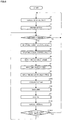
- Step S1 When an operation of a steering system starts, the torque control (the manual steering mode) by the torque control section 141 is performed (Step S1), and the motor 150 is driven by the current control/driving section 143 using the motor current command value Itref (Step S2). The above operations are repeated until the switching command SW is outputted from the switching command section 131 (Step S3).
- the target steering angle ⁇ t is inputted from the target steering angle generating section 132 (Step S4), the actual steering angle ⁇ r is inputted from the steering angle sensor 152 (Step S5), the steering torque Th is inputted from the torque sensor 154 (Step S6), the vehicle speed Vel is inputted from the vehicle speed sensor 153 (Step S7), and the motor angular speed ⁇ from the motor angular speed calculating section 144 (Step S8) to the steering angle control section 200.
- the motor current command value Imref is generated (Step S100).
- the input order of the target steering angle ⁇ t, the actual steering angle ⁇ r, the steering torque Th and the motor angular speed ⁇ is arbitrary.
- Step S10 the switching section 142 is switched by the switching command SW from the switching command section 131 so as to become the automatic steering mode (Step S10), and the motor 150 is driven by the current control/driving section 143 using the motor current command value Imref from the steering angle control section 200 (Step S11).
- the torque integral judging section 300 performs the torque integral operation to the steering torque Th (Step S200), and judges whether an integrated torque integral value (the integral output value Iout) is equal to or larger than the predetermined threshold (Step S200A).
- the steering torque judging signal TD is outputted from the torque integral judging section 300, the switching section 142 is switched, the operation returns to the above Step S1, and becomes the manual steering mode.
- the torque integral value is smaller than the threshold, the operation returns to the above Step S3, and the above operations (the automatic steering mode) are repeated.
- the torque integral judging section 300 reads the steering torque Th (Step S201) that has already inputted (Step S6), performs the noise elimination in the LPF 301 (Step S202), and calculates the absolute value
- the torque threshold Tth is previously inputted into the torque value comparing section 303, the torque value comparing section 303 judges whether the absolute value
- the torque value comparing section 303 makes the output signal Ct 0 so as not to perform the integral operation, and at the same time initializes the integral calculating section 305 by outputting the past-value initializing signal Pi (Step S206).
- the initialization is performed by resetting the past-value holding section (Z -1 ) within the integral calculating section 305 to 0.
- the integral output value Iout from the integral calculating section 305 is inputted into the switch judging section 306, and the switch judging section 306 judges whether the integral output value Iout is equal to or larger than the integral threshold Sth (Step S207).
- the switching condition is established (Step S210)
- the switch judging section 306 switches the switching section 142 by means of the steering torque judging signal TD (Step S211), and switches from the automatic steering mode to the manual steering mode (Step S212).
- the integral output value Iout is smaller than the integral threshold Sth, the switching condition is not established, so that the switching is not performed (Step S213).
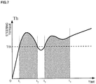
- FIG.7 shows an example of time change of the steering torque Th (Tha) to the torque threshold Tth in relation to the integral operation.
- the integration is not performed because the steering torque Th is smaller than the torque threshold Tth from a start point to a time point t 1 .
- the integration is performed because the steering torque Th is equal to or larger than the torque threshold Tth between the time point t 1 and a time point t 2 , but the switching condition is not established because the integral value is smaller than the integral threshold Sth.
- the integration is not performed because the steering torque Th is smaller than the torque threshold Tth between the time point t 2 and a time point t 3 , and the integration is performed because the steering torque Th is equal to or larger than the torque threshold Tth after the time point t 3 .
- the integral value becomes equal to or larger than the predetermined value (the integral threshold Sth), and a situation where the switching condition is established is shown.
- shaded parts shown in FIG.7 are integral domains (areas), where an example is shown that the switching condition is not established because the integral value is smaller than the integral threshold Sth at the time point t 2 , and the switching condition is established because the integral value is equal to or larger than the integral threshold Sth at the time point t 4 .
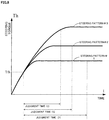
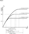
- FIG.8 shows a relation between steering patterns #1 ⁇ #3 of the steering torque Th and judgment times D1 ⁇ D3, and the torque threshold Tth is given. Then, regarding the steering patterns #1 ⁇ #3, all of the timing when the steering torque Th runs up to the torque threshold Tth are identical, after that time every steering torque Th becomes larger than the torque threshold Tth, and the integral calculation starts when the steering torque Th runs up to the torque threshold Tth. From FIG.8 , it is found out that the larger the steering torque Th, the shorter the judgment time. This is because the larger the steering torque Th, the larger a change rate of the integration, and the integral value runs up to the integral threshold Sth early.
- FIG.9 shows a configuration example (a second embodiment) of the present invention as corresponding to FIG.3 , and is totally same as the first embodiment shown in FIG.3 except a torque integral judging section 300A.
- the torque integral judging section 300A outputs the steering torque judging signal TD based on the steering torque Th as well as the first embodiment.
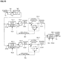
- the torque integral judging section 300A in the second embodiment is configured as shown in FIG.10 , comprises the LPF (Low-Pass Filter) 301 for eliminating the noise of the steering torque Th, the absolute value section 302 that calculates the absolute value of the steering torque Tha outputted from the LPF 301 as well as the first embodiment, and a judging part is comprised of two series in the present second embodiment.
- LPF Low-Pass Filter
- the first series comprises a torque value comparing section 303-1 that compares the absolute value
- the second series comprises a torque value comparing section 303-2 that compares the absolute value
- the switch judging section 306A may be common between the first series and the second series or be individual.
- the torque value comparing section 303-1 compares the absolute value
- is smaller than the torque threshold Tth1. That is, the torque value comparing section 303-1 performs the following operation. [TABLE 3] the output signal Ct1
- ⁇ Tth1, the output signal Ct1 0 and the past-value initializing signal Pi1 is outputted when
- the torque value comparing section 303-2 compares the absolute value
- is smaller than the torque threshold Tth2. That is, the torque value comparing section 303-2 performs the following operation. [TABLE 4] the output signal Ct2
- ⁇ Tth2, the output signal Ct2 0 and the past-value initializing signal Pi2 is outputted when
- a past-value holding section (Z -1 ) within the integral calculating section 305-1 is initialized to 0 when the past-value initializing signal Pi1 is outputted from the torque value comparing section 303-1, and similarly a past-value holding section (Z -1 ) within the integral calculating section 305-2 is initialized to 0 when the past-value initializing signal Pi2 is outputted from the torque value comparing section 303-2.
- the switch judging section 306A compares the integral output value Iout1 with the integral threshold Sth1, a switching condition is established when the integral output value Iout1 is equal to or larger than the integral threshold Sth1, and the switch judging section 306A switches from the automatic steering mode to the manual steering mode.
- the switch judging section 306A judges that the switching condition is not established when the integral output value Iout1 is smaller than the integral threshold Sth1, and continues the automatic steering mode.
- the switch judging section 306A compares the integral output value Iout2 with the integral threshold Sth2, a switching condition is established when the integral output value Iout2 is equal to or larger than the integral threshold Sth2, and the switch judging section 306A switches from the automatic steering mode to the manual steering mode.
- the switch judging section 306A judges that the switching condition is not established when the integral output value Iout2 is smaller than the integral threshold Sth2, and continues the automatic steering mode.
- the switch judging section 306A performs the following operation. [TABLE 5] the switching condition is established when Iout1 ⁇ Sth1 or Iout2 ⁇ Sth2, the switching condition is not established when Iout1 ⁇ Sth1 and Iout2 ⁇ Sth2.
- Providing the absolute value section 302 enables the judgment only by a magnitude. Further, as a configuration, it is also possible to combine the absolute value section 302 and the torque value comparing section 303-1 and 303-2, and judge the absolute value by an internal process of the torque value comparing section 303-1 and 303-2. It is also possible to calculate the absolute value after the integral calculation because the absolute value section is unnecessary in the case of setting positive and negative values of the torque threshold Tth1 and Tth2.
- Step S20 When an operation of a steering system starts, the torque control (the manual steering mode) by the torque control section 141 is performed (Step S20), the motor 150 is driven by the current control/driving section 143 using the motor current command value Itref (Step S21). The above operations are repeated until the switching command SW is outputted from the switching command section 131 (Step S22).
- the target steering angle ⁇ t is inputted from the target steering angle generating section 132 (Step S23), the actual steering angle ⁇ r is inputted from the steering angle sensor 152 (Step S24), the steering torque Th is inputted from the torque sensor 154 (Step S25), the vehicle speed Vel is inputted from the vehicle speed sensor 153 (Step S26), and the motor angular speed ⁇ from the motor angular speed calculating section 144 (Step S27) to the steering angle control section 200.
- the motor current command value Imref is generated (Step S100).
- the input order of the target steering angle ⁇ t, the actual steering angle ⁇ r, the steering torque Th and the motor angular speed ⁇ is arbitrary.
- the switching section 142 is switched by the switching command SW from the switching command section 131 so as to become the automatic steering mode (Step S30), and the motor 150 is driven by the current control/driving section 143 using the motor current command value Imref from the steering angle control section 200 (Step S31).
- the torque integral judging section 300A performs the torque integral operation to the steering torque Th (Step S300), and judges whether integrated torque integral values (the integral output values Iout1 and Iout2) are equal to or larger than predetermined thresholds (Sth1 and Sth2) (Step S300A).
- the switching condition is established when the torque integral value Iout1 or Iout2 is equal to or larger than the threshold Sth1 or Sth2, the steering torque judging signal TD is outputted from the torque integral judging section 300, the switching section 142 is switched, the operation returns to the above Step S20, and becomes the manual steering mode.
- the switching condition is not established when the torque integral values Iout1 and Iout2 are smaller than the thresholds Sth1 and Sth2, the operation returns to the above Step S22, and the above operations (the automatic steering mode) are repeated.
- Step S300 and S300A in FIG.11 the operation of the torque integral judging section 300A (Steps S300 and S300A in FIG.11 ) will be described with reference to the flowchart of FIG.12 in detail.
- the torque integral judging section 300A reads the steering torque Th (Step S301)that has already inputted (Step S25), performs the noise elimination in the LPF 301 (Step S302), and calculates the absolute value
- the torque threshold Tth1 is previously inputted into the torque value comparing section 303-1, the torque value comparing section 303-1 judges whether the absolute value
- the torque value comparing section 303-1 makes the output signal Ct1 0 so as not to perform the integral operation, and at the same time initializes the integral calculating section 305-1 by outputting the past-value initializing signal Pi1 (Step S306).
- the initialization is performed by resetting the past-value holding section (Z -1 ) within the integral calculating section 305-1 to 0.
- the torque threshold Tth2 (> Tth1) is previously inputted into the torque value comparing section 303-2, the torque value comparing section 303-2 judges whether the absolute value
- the torque value comparing section 303-2 makes the output signal Ct2 0 so as not to perform the integral operation, and at the same time initializes the integral calculating section 305-2 by outputting the past-value initializing signal Pi2 (Step S312).
- the initialization is performed by resetting the past-value holding section (Z -1 ) within the integral calculating section 305-2 to 0.
- the integral output value Iout1 from the integral calculating section 305-1 is inputted into the switch judging section 306A, the switch judging section 306A judges whether the integral output value Iout1 is equal to or larger than the integral threshold Sth1, at the same time the integral output value Iout2 from the integral calculating section 305-2 is also inputted into the switch judging section 306A, and the switch judging section 306A judges whether the integral output value Iout2 is equal to or larger than the integral threshold Sth2 (Step S320).
- Step S321 When the integral output value Iout1 is equal to or larger than the integral threshold Sth1 or the integral output value Iout2 is equal to or larger than the integral threshold Sth2, the switching condition is established (Step S321), the switch judging section 306A switches the switching section 142 by means of the steering torque judging signal TD (Step S322), and switches from the automatic steering mode to the manual steering mode (Step S323). Further, when the integral output values Iout1 and Iout2 are in cases other than the above with the integral thresholds Sth1 and Sth2, the switching condition is not established, so that the switching is not performed (Step S324) .
- FIG.13 shows a relation between steering patterns #1 ⁇ #3 of the steering torque Th and judgment times D1 ⁇ D3, and the torque thresholds Tth1 and Tth2 (> Tth1) are given.
- the torque threshold Tth2 can be made larger than the torque threshold Tth1 and the integral threshold Sth2 can be made smaller than the integral threshold Sth1 in order to make a detection time after detecting a large steering torque short.
- the judgment times D1 ⁇ D3 shown in FIG.13 are results of the torque threshold Tth1 and the integral threshold Sth1 to the steering pattern #1 ⁇ #3 respectively.
- a judgment time D3A is a result of the torque threshold Tth2 and the integral threshold Sth2. It is assumed that the steering torques Th of the steering patterns #1 and #2 are small to the torque threshold Tth2 and one of the steering pattern #3 only becomes large. It is possible to make a judgment time after the steering torque Th exceeds the torque threshold Tth2 shorter than in the case of the torque threshold Tth1 and the integral threshold Sth1. It is possible to make the timing of the judgment early by setting the torque threshold Tth2 and the integral threshold Sth2.
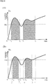
- FIG.14(A) shows an example of time change of the steering torque Th (Tha) to the torque threshold Tth1 in relation to the integral operation
- FIG.14(B) shows an example of time change of the steering torque Th (Tha) to the torque threshold Tth2 in relation to the integral operation.
- the integration is not performed because the steering torque Th is smaller than the torque threshold Tth1 from a start point to a time point t 1 .
- the integration is performed because the steering torque Th is equal to or larger than the torque threshold Tth1 between the time point t 1 and a time point t 2 , but the switching condition is not established because the integral value is smaller than the integral threshold Sth1.
- the integration is not performed because the steering torque Th is smaller than the torque threshold Tth1 between the time point t 2 and a time point t 3 , and the integration is performed because the steering torque Th is equal to or larger than the torque threshold Tth1 after the time point t 3 .
- the integral value becomes equal to or larger than the predetermined value (the integral threshold Sth1), and a situation where the switching condition is established is shown.
- shaded parts shown in FIG.14(A) are integral domains (areas), where an example is shown that the switching condition is not established because the integral value is smaller than the integral threshold Sth1 at the time point t 2 , and the switching condition is established because the integral value is equal to or larger than the integral threshold Sth1 at the time point t 4 .
- the torque threshold Tth2 is set larger than the torque threshold Tth1, and the integration is not performed because the steering torque Th is smaller than the torque threshold Tth2 from a start point to a time point t 10 .
- the integration is performed because the steering torque Th is equal to or larger than the torque threshold Tth2 between the time point t 10 and a time point t 20 , but the switching condition is not established because the integral value is smaller than the integral threshold Sth2.
- the integration is not performed because the steering torque Th is smaller than the torque threshold Tth2 between the time point t 20 and a time point t 30 , and the integration is performed because the steering torque Th is equal to or larger than the torque threshold Tth2 after the time point t 30 .
- the integral value becomes equal to or larger than the predetermined value (the integral threshold Sth2), and a situation where the switching condition is established is shown.
- shaded parts shown in FIG.14(B) are integral domains (areas), where an example is shown that the switching condition is not established because the integral value is smaller than the integral threshold Sth2 at the time point t 20 , and the switching condition is established because the integral value is equal to or larger than the integral threshold Sth2 at the time point t 40 .
Description
- The present invention relates to an electric power steering apparatus that has functions of an automatic steering mode (a parking support mode) and a manual steering mode and provides a steering system of a vehicle with an assist force by means of a motor, and in particular to an electric power steering apparatus that improves performance of a switching judgment from the automatic steering mode to the manual steering mode.
- An electric power steering apparatus which provides a steering mechanism of a vehicle with a steering assist torque (assist force) by means of rotational torque of a motor applies driving force of the motor as the steering assist torque to a steering shaft or a rack shaft by means of a transmission mechanism such as gears or a belt through a reduction mechanism. In order to accurately generate the steering assist torque, such a conventional electric power steering (EPS) apparatus performs a feedback control of a motor current. The feedback control adjusts a voltage supplied to the motor so that a difference between a steering assist command value (a current command value) and a detected motor current value becomes small, and the adjustment of the voltage supplied to the motor is generally performed by an adjustment of a duty of a PWM (Pulse Width Modulation) control.
- A general configuration of a conventional electric power steering apparatus will be described with reference to
FIG.1 . As shown inFIG.1 , a column shaft (a steering shaft) 2 connected to a steering handle (a steering wheel) 1 is connected to steeredwheels reduction gears 3,universal joints pinion mechanism 5, andtie rods hub units column shaft 2 is provided with atorque sensor 10 for detecting a steering torque of thesteering wheel 1, and amotor 20 for assisting the steering force of thesteering wheel 1 is connected to thecolumn shaft 2 through thereduction gears 3. Electric power is supplied to a control unit (ECU) 100 for controlling the electric power steering apparatus from abattery 13, and an ignition key signal is inputted into thecontrol unit 100 through anignition key 11. Thecontrol unit 100 calculates a steering assist command value of an assist (steering assist) command based on the steering torque Th detected by thetorque sensor 10 and a vehicle speed Vel detected by avehicle speed sensor 12, and controls a current supplied to themotor 20 based on a current control value E obtained by performing compensation and so on with respect to the steering assist command value. Moreover, it is also possible to receive the vehicle speed Vel from a CAN (Controller Area Network) and so on. - In such the electric power steering apparatus, the
control unit 100 is, for example, configured as shown inFIG.2 disclosed in Japanese Published Unexamined Patent Application No.2002-369565 A - In
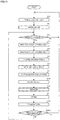
FIG.2 , themotor 20 that generates the steering assist torque of the electric power steering apparatus is driven by amotor driving section 21, themotor driving section 21 is controlled by thecontrol unit 100 shown by a two-dot chain line, and the the steering torque Th from thetorque sensor 10 and the vehicle speed Vel from the vehicle speed detecting system are inputted into thecontrol unit 100. A voltage Vm between the motor terminals and a motor current value i are measured and outputted in themotor 20. - The
control unit 100 comprises a torquesystem control section 110 that performs the control by means of the steering torque Th and is shown by a broken line, and a motor system control section 120 that performs the control related to a drive of themotor 20 and is shown by a dashed line. The torquesystem control section 110 comprises an assist amount calculating section 111, adifferential control section 112, a yaw-rateconvergence control section 113, a robuststabilization compensating section 114, and a self aligning torque (SAT)estimation feedback section 115, and includes an addingsection subtracting section 116C. Further, the motor system control section 120 comprises acompensating section 121, adisturbance estimating section 122, a motor angularspeed calculating section 123, a motor angularacceleration calculating section 124, and a motorcharacteristic compensating section 125, and includes an addingsection 126A and 126B. - The steering torque Th is inputted into the assist amount calculating section 111, the
differential control section 112, the yaw-rateconvergence control section 113 and the SATestimation feedback section 115, which all input the vehicle speed Vel as a parameter. The assist amount calculating section 111 calculates an assist torque amount based on the steering torque Th. The yaw-rateconvergence control section 113 inputs the steering torque Th and a motor angular speed ω, and puts a brake on an action of the steering wheel whirling in order to improve the convergence of the vehicle yaw. Further, thedifferential control section 112 improves the control responsibility near a neutral point of the steering wheel, and achieves smooth steering. The SATestimation feedback section 115 inputs the steering torque Th, a signal made by adding an output from thedifferential control section 112 to an output from the assist amount calculating section 111 in the addingsection 116A, the motor angular speed ω calculated in the motor angularspeed calculating section 123 and a motor angular acceleration α, estimates an SAT, performs signal processing of the estimated SAT by means of a feedback filter, and gives an appropriate road-surface information to the steering wheel as reaction force. - Further, a signal made in the adding
section 116B by adding an output from the yaw-rateconvergence control section 113 to a signal made in the addingsection 116A by adding an output from thedifferential control section 112 to an output from the assist amount calculating section 111 is inputted as an assist amount AQ into the robuststabilization compensating section 114. The robuststabilization compensating section 114 is, for example, a compensating section shown in Japanese Published Unexamined Patent Application No.H8-290778 A estimation feedback section 115 from an output of the robuststabilization compensating section 114 in thesubtracting section 116C. - Moreover, the motor angular
speed calculating section 123 calculates the motor angular speed ω based on the voltage Vm between the motor terminals and the motor current value i, and the motor angular speed ω is inputted into the motor angularacceleration calculating section 124, the yaw-rateconvergence control section 113 and the SATestimation feedback section 115. The motor angularacceleration calculating section 124 calculates the motor angular acceleration α based on the inputted motor angular speed ω, and the calculated motor angular acceleration α is inputted into the motorcharacteristic compensating section 125 and the SATestimation feedback section 115. The assist amount Ia left by the subtraction of the output of the SATestimation feedback section 115 from the output of the robuststabilization compensating section 114 is added to an output Ic of the motorcharacteristic compensating section 125 in the addingsection 126A, and the adding signal is inputted as a current command value Ir into the compensatingsection 121 comprising a differential compensating section and so on. A signal made in the adding section 126B by adding an output from thedisturbance estimating section 122 to a current command value Ira compensated in the compensatingsection 121 inputted into themotor driving section 21 and thedisturbance estimating section 122. The disturbance estimatingsection 122 is such an apparatus as shown in Japanese Published Unexamined Patent Application No.H8-310417 A disturbance estimating section 122 to the current command value Ira that is a control target of a motor output and is compensated in the compensatingsection 121 and the motor current value i, and prevents the loss of the stability of the control system. - In such the electric power steering apparatus, vehicles provided with a parking support function (parking assist) and switching an automatic steering mode and a manual steering mode recently appear. The vehicle provided with the parking support function sets a target steering angle based on data such as a camera (an image), a distance sensor and so on, and performs automatic control according to the target steering angle.
- In the electric power steering apparatus having the well-known functions of the automatic steering mode (the parking support mode) and the manual steering mode, back parking and parallel parking are hitherto performed automatically by controlling an actuator (a motor) based on the relation between a vehicle moving distance and a steering angle stored beforehand.
- Thus the conventional electric power steering apparatus stops the automatic steering control when a driver steers a steering wheel in the automatic steering mode and the steering torque is judged to exceed a predetermined value set beforehand. However, when performing the judgment only by comparing the output of the torque sensor with the predetermined value, there is a problem that the output of the torque sensor exceeds the predetermined value temporarily because of a noise of the torque sensor or an inertial torque of the steering wheel appearing in the case of a tire stepping on a pebble or automatic steering by the motor, and each time the automatic steering control is made stopped. When the predetermined value is set to high in order to avoid such an inconvenience, not only does the interaction between the automatic steering mode and the manual steering mode give uncomfortable feeling to the driver, but also there is a possibility that the automatic steering control is not immediately stopped even if the driver steers the steering wheel in the automatic steering control.
- As an automatic steering apparatus solving such a problem, for example, Japanese Patent No.
3845188 B2 Patent Document 1 sets plural kinds of the predetermined values and changes a predetermined time corresponding to each predetermined value in an automatic steering apparatus for a vehicle that comprises a moving locus setting means for storing or calculating vehicle moving locus to a target position, an actuator (a motor) for steering a wheel, a steering torque detecting means (a torque sensor) for detecting a steering torque that a driver applies to a steering wheel, and an actuator control means for controlling the actuator drive based on the moving locus set by the moving locus setting means and at the same time stopping an actuator control based on the moving locus when the steering torque over the predetermined value set beforehand is detected for more than the predetermined time. -
EP 1 864 889 A2claim 1 which includes a steering actuator (M) that imparts a steering force to a steering mechanism of a vehicle; an automatic steering controller that performs an automatic steering control by controlling the steering actuator (M); a driving state detector that detects a driving state of the vehicle during the automatic steering control; a threshold value setting unit that variably sets a threshold value for permitting an intervention in the automatic steering control; and an automatic steering intervention unit that intervenes in the automatic steering control based on a threshold value set by the threshold value setting unit. - Patent Document 1: Japanese Patent No.
3845188 B2 EP 1 864 889 A2 - However, the apparatus disclosed in
Patent Document 1 stops the automatic steering control when the predetermined time corresponding to the steering torque of the driver passes. There are problems that it is complicated to set plural kinds of the predetermined values and change the predetermined time corresponding to each predetermined value, and a calculation load is large. - The present invention has been developed in view of the above-described circumstances, and an object of the present invention is to provide an electric power steering apparatus that does not give uncomfortable feeling to the driver in the vehicle having functions of the automatic steering mode and the manual steering mode by detecting that the driver steers the steering wheel in the automatic steering mode by means of the steering torque from the torque sensor and switching to the manual steering mode when a capacity (an integrated value) corresponding to the occurring torque magnitude becomes over a predetermined value or over a predetermined value set finely.
- The present invention relates to an electric power steering apparatus in accordance with the appended claims. There is disclosed an electric power steering apparatus that calculates a motor
current command value 1 based on a steering torque and a vehicle speed, drives a motor based on said motorcurrent command value 1 so as to perform an assist control of a steering system, and has a function for switching an automatic steering mode and a manual steering mode, the above-described object of the present invention is achieved by that comprising: a steering angle control section that calculates a motorcurrent command value 2 to get an actual steering angle close to a target steering angle; a torque integral judging section that outputs a steering torque judging signal by integrating said steering torque, which is compared with a predetermined threshold; and a switching section that inputs said motorcurrent command value 1 and said motorcurrent command value 2, and is switched in accordance with a switching signal or said steering torque judging signal; wherein said torque integral judging section comprises a torque value comparing section that compares an absolute value of said steering torque with a torque threshold so as to output a predetermined signal, an integral calculating section that integrates said predetermined signal, and a switch judging section that compares an integral value from said integral calculating section with an integral threshold so as to output said steering torque judging signal; and wherein said switching section is switched depending on a switching command of said automatic steering mode and said manual steering mode or said steering torque judging signal. - There is further disclosed an electric power steering apparatus that calculates a motor
current command value 1 based on a steering torque and a vehicle speed, drives a motor based on said motorcurrent command value 1 so as to perform an assist control of a steering system, and has a function for switching an automatic steering mode and a manual steering mode, the above-described object of the present invention is achieved by that comprising: a steering angle control section that calculates a motorcurrent command value 2 to get an actual steering angle close to a target steering angle; a torque integral judging section that outputs a steering torque judging signal by integrating said steering torque, which is compared with a predetermined threshold; and a switching section that inputs said motorcurrent command value 1 and said motorcurrent command value 2, and is switched in accordance with a switching signal or said steering torque judging signal; wherein said torque integral judging section comprises plural torque value comparing sections that compare an absolute value of said steering torque with plural torque thresholds so as to output each predetermined signal, plural integral calculating sections that integrate said each predetermined signal, and a switch judging section that compares each integral value from said plural integral calculating sections with corresponding plural integral thresholds so as to output said steering torque judging signal; and wherein said switching section is switched depending on a switching command of said automatic steering mode and said manual steering mode or said steering torque judging signal. - According to the electric power steering apparatus of the present invention, it is possible in the vehicle having the automatic steering mode (the parking support function) and the manual steering mode to shorten the time required for switching judgment as the steering torque is larger because of integrating the steering torque when the steering torque becomes over a predetermined torque threshold and moreover performing the switching control by comparing the magnitude of the integrated value with a predetermined integral threshold. The electric power steering apparatus does not give uncomfortable feeling to the driver especially in case of switching to the manual steering mode in the automatic steering mode because of performing the switching judgment not by passage of time but by the integrated value of the steering torque.
- Further, there is an advantage that it is not necessary to have plural thresholds of the steering torque and plural setting values of the judgment time, a configuration is simple, and it is possible to decrease a calculation load.
- The present disclosure further comprises the following aspects and embodiments:
- In a first paragraph, an electric power steering apparatus that calculates a motor
current command value 1 based on a steering torque and a vehicle speed, drives a motor based on said motorcurrent command value 1 so as to perform an assist control of a steering system, and has a function for switching an automatic steering mode and a manual steering mode, comprising: - a steering angle control section that calculates a motor
current command value 2 to get an actual steering angle close to a target steering angle; - a torque integral judging section that outputs a steering torque judging signal by integrating said steering torque, which is compared with a predetermined threshold; and
- a switching section that inputs said motor
current command value 1 and said motorcurrent command value 2, and is switched in accordance with a switching signal or said steering torque judging signal; - wherein said torque integral judging section comprises a torque value comparing section that compares an absolute value of said steering torque with a torque threshold so as to output a predetermined signal, an integral calculating section that integrates said predetermined signal, and a switch judging section that compares an integral value from said integral calculating section with an integral threshold so as to output said steering torque judging signal; and
- wherein said switching section is switched depending on a switching command of said automatic steering mode and said manual steering mode or said steering torque judging signal.
- In a second paragraph, the electric power steering apparatus according to the first paragraph, wherein
said torque integral judging section comprises an LPF in a front stage of said torque value comparing section. - In a third paragraph, the electric power steering apparatus according to the first or second paragraph, wherein
said torque value comparing section includes a function for outputting said absolute value when said absolute value is equal to or larger than said torque threshold, and outputting 0 and at the same time outputting a past-value initializing signal to initialize said integral calculating section when said absolute value is smaller than said torque threshold. - In a fourth paragraph, the electric power steering apparatus according to any one of the first to third paragraph, wherein
said switch judging section includes a function for outputting said steering torque judging signal when said integral value is equal to or larger than said integral threshold, and not outputting said steering torque judging signal when said integral value is smaller than said integral threshold. - In a fifth paragraph, the electric power steering apparatus according to any one of the first to fourth paragraph, wherein
said switching section is switched in accordance with said steering torque judging signal so as to switch to said manual steering mode when said absolute value is equal to or larger than said torque threshold and said integral value becomes equal to or larger than said integral threshold in said automatic steering mode. - In a sixth paragraph, an electric power steering apparatus that calculates a motor
current command value 1 based on a steering torque and a vehicle speed, drives a motor based on said motorcurrent command value 1 so as to perform an assist control of a steering system, and has a function for switching an automatic steering mode and a manual steering mode, comprising: - a steering angle control section that calculates a motor
current command value 2 to get an actual steering angle close to a target steering angle; - a torque integral judging section that outputs a steering torque judging signal by integrating said steering torque, which is compared with a predetermined threshold; and
- a switching section that inputs said motor
current command value 1 and said motorcurrent command value 2, and is switched in accordance with a switching signal or said steering torque judging signal; - wherein said torque integral judging section comprises plural torque value comparing sections that compare an absolute value of said steering torque with plural torque thresholds so as to output each predetermined signal, plural integral calculating sections that integrate said each predetermined signal, and a switch judging section that compares each integral value from said plural integral calculating sections with corresponding plural integral thresholds so as to output said steering torque judging signal; and
- wherein said switching section is switched depending on a switching command of said automatic steering mode and said manual steering mode or said steering torque judging signal.
- In a seventh paragraph, the electric power steering apparatus according to the sixth paragraph, wherein
said torque integral judging section comprises an LPF in a front stage of said plural torque value comparing sections. - In a eighth paragraph, the electric power steering apparatus according to the sixth or seventh paragraph, wherein
said plural torque value comparing sections respectively include a function for outputting said absolute value when said absolute value is equal to or larger than a self-corresponding torque threshold, and outputting 0 and at the same time outputting a past-value initializing signal to initialize self-corresponding said integral calculating section when said absolute value is smaller than said self-corresponding torque threshold. - In a ninth paragraph, the electric power steering apparatus according to any one of the sixth to eighth paragraph, wherein
said switch judging section includes a function for outputting said steering torque judging signal when said plural integral values are respectively equal to or larger than corresponding said plural integral thresholds, and not outputting said steering torque judging signal in any other case. - In a tenth paragraph, the electric power steering apparatus according to any one of the sixth to ninth paragraph, wherein
said switching section is switched in accordance with said steering torque judging signal so as to switch to said manual steering mode when said absolute value is equal to or larger than said self-corresponding torque threshold and said integral value becomes equal to or larger than said self-corresponding integral threshold in said automatic steering mode. - In a eleventh paragraph, the electric power steering apparatus according to any one of the sixth to tenth paragraph, wherein
said plural torque value comparing sections and said plural integral calculating sections are respectively comprised of two sections. - In the accompanying drawings:
-
FIG.1 is a configuration diagram illustrating a general outline of an electric power steering apparatus; -
FIG.2 is a block diagram showing a configuration example of a control system in a conventional electric power steering apparatus; -
FIG.3 is a block diagram showing a configuration example (a first embodiment) of the present invention; -
FIG.4 is a block diagram showing a configuration example of a torque integral judging section; -
FIG.5 is a flowchart showing an operating example (a first embodiment) of the present invention; -
FIG.6 is a flowchart showing an operating example of the torque integral judging section; -
FIG.7 is a timing chart showing an operating example of a steering torque and an integral; -
FIG.8 is a characteristic diagram showing a relation between the steering torque and a judgment time; -
FIG.9 is a block diagram showing a configuration example (a second embodiment) of the present invention; -
FIG.10 is a block diagram showing a configuration example of the torque integral judging section; -
FIG.11 is a flowchart showing an operating example (a second embodiment) of the present invention; -
FIG.12 is a flowchart showing an operating example of the torque integral judging section; -
FIG.13 is a diagram for describing an operation of the present invention;
and -
FIG.14 is a timing chart showing an operating example of the steering torque and the integral compared with each two thresholds. - The present invention, in an electric power steering apparatus of a vehicle having functions of an automatic steering mode and a manual steering mode, detects that a driver steers a steering wheel in the automatic steering mode by means of a steering torque from a torque sensor, at the same time switches to the manual steering mode when a capacity (an integrated value) corresponding to the occurring torque magnitude becomes over a predetermined value, and does not give uncomfortable feeling to the driver in any situation.
- In the case of performing the judgment by means of plural thresholds, it is possible to give uncomfortable feeling to the driver in any situation and attain the quick and certain switching to the manual steering mode.
- Hereinafter, an embodiment of the present invention will be described with reference to the accompanying drawings in detail.
-
FIG.3 shows a configuration example (a first embodiment) of the present invention. Arotation angle sensor 151, such as a resolver and so on, for detecting a motor rotation angle θs is connected to amotor 150, and themotor 150 is driven and controlled through a vehicle-side ECU 130 and an electric power steering apparatus (EPS)-side ECU 140. - The vehicle-
side ECU 130 comprises a switchingcommand section 131 that outputs a switching command SW of either an automatic steering mode or a manual steering mode based on a button, a switch and so on to show a driver's intention, and a target steeringangle generating section 132 that generates a target steering angle θt based on a signal from a camera (an image), a distance sensor and so on. Further, an actual steering angle θr detected by asteering angle sensor 152 which a column shaft is provided with and a vehicle speed Vel from avehicle speed sensor 153 are inputted through the vehicle-side ECU 130 into a steeringangle control section 200 within the EPS-side ECU 140. An output from thesteering angle sensor 152 may be an estimated value of a steering angle estimated by the column shaft (including an intermediate shaft and a pinion shaft), a displacement of a rack of a rack and pinion, a wheel speed and so on. Further, it is also possible to receive the vehicle speed Vel from a CAN and so on. - The switching
command section 131 outputs the switching command SW based on a signal for identifying whether to enter the automatic steering mode, for example a signal of a vehicle state by means of the button or the switch which a dashboard or a steering wheel area is provided with to show the driver's intention, a parking mode set in a shift and so on, and inputs the switching command SW into aswitching section 142 within the EPS-side ECU 140. Further, the target steeringangle generating section 132 generates the target steering angle θt based on data from the camera (the image), the distance sensor and so on by a well-known manner, and inputs the generated target steering angle θt into the steeringangle control section 200 within the EPS-side ECU 140. - The EPS-
side ECU 140 comprises atorque control section 141 that outputs a motor current command value Itref that is calculated based on a steering torque Th from atorque sensor 154 and a motor angular speed ω, the steeringangle control section 200 that calculates and outputs a motor current command value Imref for an automatic control of a steering angle based on the target steering angle θt, the actual steering angle θr, the vehicle speed Vel, the steering torque Th and the motor angular speed ω, theswitching section 142 that switches the motor current command value Itref and the motor current command value Imref by means of the switching command SW from the switchingcommand section 131 or a steering torque judging signal TD and outputs a motor current command value Iref, a current control/driving section 143 that drives and controls themotor 150 based on the motor current command value Iref (Itref or Imref) from theswitching section 142, a motor angularspeed calculating section 144 that calculates the motor angular speed ω based on the motor rotation angle θs from therotation angle sensor 151, and a torqueintegral judging section 300 that outputs the steering torque judging signal TD based on the steering torque Th. The steeringangle control section 200 calculates the motor current command value Imref to get the actual steering angle θr close to the target steering angle θ1. - The
switching section 142 switches a torque control mode (the manual steering mode) by thetorque control section 141 and the automatic steering mode by the steeringangle control section 200 based on the switching command SW from the switchingcommand section 131 within the vehicle-side ECU 130 or the steering torque judging signal TD from the torqueintegral judging section 300, outputs the motor current command value Itref as the motor current command value Iref in the manual steering mode, and outputs the motor current command value Imref as the motor current command value Iref in the automatic steering mode. Further, the current control/driving section 143 comprises a PI current control section, a PWM control section, an inverter and so on. - The torque
integral judging section 300 is configured as shown inFIG.4 , and comprises an LPF (Low-Pass Filter) 301 for eliminating a noise of the steering torque Th, anabsolute value section 302 that calculates an absolute value of a steering torque Tha outputted from theLPF 301, a torquevalue comparing section 303 that compares an absolute value of the steering torque Tha with a predetermined torque threshold Tth and outputs an output signal Ct or a past-value initializing signal Pi, alimiter 304 that limits an upper and a lower limits of the output signal Ct so as not to input an excessive signal, anintegral calculating section 305 that integrates an integral input value Cta from thelimiter 304, and aswitch judging section 306 that compares an integral output value Iout integrated by theintegral calculating section 305 with a predetermined integral threshold Sth and outputs the steering torque judging signal TD. - The
LPF 301 for eliminating the noise of the steering torque Th is provided in order to avoid the steering torque exceeding a predetermined value temporarily because of an inertial torque of a steering wheel when a tire collides with a curb, a stone and so on, or switching the automatic steering control or making it hard to switch the automatic steering control when the steering torque Th is no larger than the predetermined value. The torquevalue comparing section 303 compares the absolute value |Tha| of the steering torque Tha with the torque threshold Tth, performs an integral operation when the absolute value |Tha| is equal to or larger than the torque threshold Tth, and initializes the integral value to 0 when the absolute value |Tha| is smaller than the torque threshold Tth. That is, the torquevalue comparing section 303 performs the following operation.[TABLE 1] the output signal Ct = |Tha| when |Tha| ≥ Tth, the output signal Ct = 0 and the past-value initializing signal Pi is outputted when |Tha| < Tth. - A past-value holding section (Z-1) within the
integral calculating section 305 is initialized to 0 when the past-value initializing signal Pi is outputted from the torquevalue comparing section 303. Further, theswitch judging section 306 compares the integral output value Iout with the integral threshold Sth, a switching condition is established when the integral output value Iout is equal to or larger than the integral threshold Sth, and theswitch judging section 306 switches from the automatic steering mode to the manual steering mode. Theswitch judging section 306 judges that the switching condition is not established when the integral output value Iout is smaller than the integral threshold Sth, and continues the automatic steering mode. That is, theswitch judging section 306 performs the following operation.[TABLE 2] the switching condition is established when Iout ≥ Sth, the switching condition is not established when Iout < Sth. - Providing the
absolute value section 302 enables the judgment only by a magnitude. Therefore, it is possible to judge by comparison with the single torque threshold Tth. Further, as a configuration, it is also possible to combine theabsolute value section 302 and the torquevalue comparing section 303, and judge the absolute value by an internal process of the torquevalue comparing section 303. It is also possible to calculate the absolute value after the integral calculation because the absolute value section is unnecessary in the case of setting positive and negative values of the torque threshold Tth. - In such a configuration, that whole operating example (a first embodiment) will be described with reference to the flowchart of
FIG.5 . - When an operation of a steering system starts, the torque control (the manual steering mode) by the
torque control section 141 is performed (Step S1), and themotor 150 is driven by the current control/driving section 143 using the motor current command value Itref (Step S2). The above operations are repeated until the switching command SW is outputted from the switching command section 131 (Step S3). - When the switching command SW is outputted from the switching
command section 131 by switching to the automatic steering mode, the target steering angle θt is inputted from the target steering angle generating section 132 (Step S4), the actual steering angle θr is inputted from the steering angle sensor 152 (Step S5), the steering torque Th is inputted from the torque sensor 154 (Step S6), the vehicle speed Vel is inputted from the vehicle speed sensor 153 (Step S7), and the motor angular speed ω from the motor angular speed calculating section 144 (Step S8) to the steeringangle control section 200. In the steeringangle control section 200, the motor current command value Imref is generated (Step S100). Moreover, the input order of the target steering angle θt, the actual steering angle θr, the steering torque Th and the motor angular speed ω is arbitrary. - Thereafter, the
switching section 142 is switched by the switching command SW from the switchingcommand section 131 so as to become the automatic steering mode (Step S10), and themotor 150 is driven by the current control/driving section 143 using the motor current command value Imref from the steering angle control section 200 (Step S11). - In such the automatic steering mode, the torque
integral judging section 300 performs the torque integral operation to the steering torque Th (Step S200), and judges whether an integrated torque integral value (the integral output value Iout) is equal to or larger than the predetermined threshold (Step S200A). When the torque integral value is equal to or larger than the threshold, the steering torque judging signal TD is outputted from the torqueintegral judging section 300, theswitching section 142 is switched, the operation returns to the above Step S1, and becomes the manual steering mode. When the torque integral value is smaller than the threshold, the operation returns to the above Step S3, and the above operations (the automatic steering mode) are repeated. - Next, the operation of the torque integral judging section 300 (Steps S200 and S200A in
FIG.5 ) will be described with reference to the flowchart ofFIG.6 in detail. - The torque
integral judging section 300 reads the steering torque Th (Step S201) that has already inputted (Step S6), performs the noise elimination in the LPF 301 (Step S202), and calculates the absolute value |Tha| of the steering torque Tha from theLPF 301 in the absolute value section 302 (Step S203). The torque threshold Tth is previously inputted into the torquevalue comparing section 303, the torquevalue comparing section 303 judges whether the absolute value |Tha| is equal to or larger than the torque threshold Tth (Step S204), inputs the output signal Ct as the absolute value |Tha| into theintegral calculating section 305 when the absolute value |Tha| is equal to or larger than the torque threshold Tth, and the torqueintegral judging section 300 performs the integral operation in the integral calculating section 305 (Step S205). Further, when the absolute value |Tha| is smaller than the torque threshold Tth, the torquevalue comparing section 303 makes theoutput signal Ct 0 so as not to perform the integral operation, and at the same time initializes theintegral calculating section 305 by outputting the past-value initializing signal Pi (Step S206). The initialization is performed by resetting the past-value holding section (Z-1) within theintegral calculating section 305 to 0. - The integral output value Iout from the
integral calculating section 305 is inputted into theswitch judging section 306, and theswitch judging section 306 judges whether the integral output value Iout is equal to or larger than the integral threshold Sth (Step S207). When the integral output value Iout is equal to or larger than the integral threshold Sth, the switching condition is established (Step S210), theswitch judging section 306 switches theswitching section 142 by means of the steering torque judging signal TD (Step S211), and switches from the automatic steering mode to the manual steering mode (Step S212). Further, when the integral output value Iout is smaller than the integral threshold Sth, the switching condition is not established, so that the switching is not performed (Step S213). -
FIG.7 shows an example of time change of the steering torque Th (Tha) to the torque threshold Tth in relation to the integral operation. The integration is not performed because the steering torque Th is smaller than the torque threshold Tth from a start point to a time point t1. The integration is performed because the steering torque Th is equal to or larger than the torque threshold Tth between the time point t1 and a time point t2, but the switching condition is not established because the integral value is smaller than the integral threshold Sth. Then, the integration is not performed because the steering torque Th is smaller than the torque threshold Tth between the time point t2 and a time point t3, and the integration is performed because the steering torque Th is equal to or larger than the torque threshold Tth after the time point t3. At a time point t4, the integral value becomes equal to or larger than the predetermined value (the integral threshold Sth), and a situation where the switching condition is established is shown. In other words, shaded parts shown inFIG.7 are integral domains (areas), where an example is shown that the switching condition is not established because the integral value is smaller than the integral threshold Sth at the time point t2, and the switching condition is established because the integral value is equal to or larger than the integral threshold Sth at the time point t4. -
FIG.8 shows a relation betweensteering patterns # 1∼#3 of the steering torque Th and judgment times D1∼D3, and the torque threshold Tth is given. Then, regarding thesteering patterns # 1∼#3, all of the timing when the steering torque Th runs up to the torque threshold Tth are identical, after that time every steering torque Th becomes larger than the torque threshold Tth, and the integral calculation starts when the steering torque Th runs up to the torque threshold Tth. FromFIG.8 , it is found out that the larger the steering torque Th, the shorter the judgment time. This is because the larger the steering torque Th, the larger a change rate of the integration, and the integral value runs up to the integral threshold Sth early. - Moreover, it is also possible to change the motor current command value gradually using a fading gain in the case of switching the steering mode in the
switching section 142. -
FIG.9 shows a configuration example (a second embodiment) of the present invention as corresponding toFIG.3 , and is totally same as the first embodiment shown inFIG.3 except a torqueintegral judging section 300A. The torqueintegral judging section 300A outputs the steering torque judging signal TD based on the steering torque Th as well as the first embodiment. - The torque
integral judging section 300A in the second embodiment is configured as shown inFIG.10 , comprises the LPF (Low-Pass Filter) 301 for eliminating the noise of the steering torque Th, theabsolute value section 302 that calculates the absolute value of the steering torque Tha outputted from theLPF 301 as well as the first embodiment, and a judging part is comprised of two series in the present second embodiment. - That is, the first series comprises a torque value comparing section 303-1 that compares the absolute value |Tha| of the steering torque Tha with a predetermined torque threshold Tth1 and outputs an output signal Ct1 or a past-value initializing signal Pi1, a limiter 304-1 that limits an upper and a lower limits of the output signal Ct1 so as not to input an excessive signal, an integral calculating section 305-1 that integrates an integral input value Cta1 from the limiter 304-1, and a
switch judging section 306A that inputs an integral output value Iout1 integrated by the integral calculating section 305-1, compares the integral output value Iout1 with a predetermined integral threshold Sth1 and outputs the steering torque judging signal TD. Similarly, the second series comprises a torque value comparing section 303-2 that compares the absolute value |Tha| of the steering torque Tha with a predetermined torque threshold Tth2 (> Tth1) and outputs an output signal Ct2 or a past-value initializing signal Pi2, a limiter 304-2 that limits an upper and a lower limits of the output signal Ct2 so as not to input an excessive signal, an integral calculating section 305-2 that integrates an integral input value Cta2 from the limiter 304-2, and theswitch judging section 306A that inputs an integral output value Iout2 integrated by the integral calculating section 305-2, compares the integral output value Iout2 with a predetermined integral threshold Sth2 (< Sth1) and outputs the steering torque judging signal TD. Theswitch judging section 306A may be common between the first series and the second series or be individual. - The torque value comparing section 303-1 compares the absolute value |Tha| of the steering torque Tha with the torque threshold Tth1, performs an integral operation in the integral calculating section 305-1 through the limiter 304-1 when the absolute value |Tha| is equal to or larger than the torque threshold Tth1, and initializes the integral value to 0 when the absolute value |Tha| is smaller than the torque threshold Tth1. That is, the torque value comparing section 303-1 performs the following operation.
[TABLE 3] the output signal Ct1 = |Tha| when |Tha| ≥ Tth1, the output signal Ct1 = 0 and the past-value initializing signal Pi1 is outputted when |Tha| < Tth1. - Similarly, the torque value comparing section 303-2 compares the absolute value |Tha| of the steering torque Tha with the torque threshold Tth2, performs an integral operation in the integral calculating section 305-2 through the limiter 304-2 when the absolute value |Tha| is equal to or larger than the torque threshold Tth2, and initializes the integral value to 0 when the absolute value |Tha| is smaller than the torque threshold Tth2. That is, the torque value comparing section 303-2 performs the following operation.
[TABLE 4] the output signal Ct2 = |Tha| when |Tha| ≥ Tth2, the output signal Ct2 = 0 and the past-value initializing signal Pi2 is outputted when |Tha| < Tth2. - A past-value holding section (Z-1) within the integral calculating section 305-1 is initialized to 0 when the past-value initializing signal Pi1 is outputted from the torque value comparing section 303-1, and similarly a past-value holding section (Z-1) within the integral calculating section 305-2 is initialized to 0 when the past-value initializing signal Pi2 is outputted from the torque value comparing section 303-2.
- The
switch judging section 306A compares the integral output value Iout1 with the integral threshold Sth1, a switching condition is established when the integral output value Iout1 is equal to or larger than the integral threshold Sth1, and theswitch judging section 306A switches from the automatic steering mode to the manual steering mode. Theswitch judging section 306A judges that the switching condition is not established when the integral output value Iout1 is smaller than the integral threshold Sth1, and continues the automatic steering mode. Further, theswitch judging section 306A compares the integral output value Iout2 with the integral threshold Sth2, a switching condition is established when the integral output value Iout2 is equal to or larger than the integral threshold Sth2, and theswitch judging section 306A switches from the automatic steering mode to the manual steering mode. Theswitch judging section 306A judges that the switching condition is not established when the integral output value Iout2 is smaller than the integral threshold Sth2, and continues the automatic steering mode. - That is, the
switch judging section 306A performs the following operation.[TABLE 5] the switching condition is established when Iout1 ≥ Sth1 or Iout2 ≥ Sth2, the switching condition is not established when Iout1 < Sth1 and Iout2 < Sth2. - Providing the
absolute value section 302 enables the judgment only by a magnitude. Further, as a configuration, it is also possible to combine theabsolute value section 302 and the torque value comparing section 303-1 and 303-2, and judge the absolute value by an internal process of the torque value comparing section 303-1 and 303-2. It is also possible to calculate the absolute value after the integral calculation because the absolute value section is unnecessary in the case of setting positive and negative values of the torque threshold Tth1 and Tth2. - In such a configuration, that whole operating example (a second embodiment) will be described with reference to the flowchart of
FIG.11 . - When an operation of a steering system starts, the torque control (the manual steering mode) by the
torque control section 141 is performed (Step S20), themotor 150 is driven by the current control/driving section 143 using the motor current command value Itref (Step S21). The above operations are repeated until the switching command SW is outputted from the switching command section 131 (Step S22). - When the switching command SW is outputted from the switching
command section 131 by switching to the automatic steering mode, the target steering angle θt is inputted from the target steering angle generating section 132 (Step S23), the actual steering angle θr is inputted from the steering angle sensor 152 (Step S24), the steering torque Th is inputted from the torque sensor 154 (Step S25), the vehicle speed Vel is inputted from the vehicle speed sensor 153 (Step S26), and the motor angular speed ω from the motor angular speed calculating section 144 (Step S27) to the steeringangle control section 200. In the steeringangle control section 200, the motor current command value Imref is generated (Step S100). Moreover, the input order of the target steering angle θt, the actual steering angle θr, the steering torque Th and the motor angular speed ω is arbitrary. - Thereafter, the
switching section 142 is switched by the switching command SW from the switchingcommand section 131 so as to become the automatic steering mode (Step S30), and themotor 150 is driven by the current control/driving section 143 using the motor current command value Imref from the steering angle control section 200 (Step S31). - In such the automatic steering mode, the torque
integral judging section 300A performs the torque integral operation to the steering torque Th (Step S300), and judges whether integrated torque integral values (the integral output values Iout1 and Iout2) are equal to or larger than predetermined thresholds (Sth1 and Sth2) (Step S300A). The switching condition is established when the torque integral value Iout1 or Iout2 is equal to or larger than the threshold Sth1 or Sth2, the steering torque judging signal TD is outputted from the torqueintegral judging section 300, theswitching section 142 is switched, the operation returns to the above Step S20, and becomes the manual steering mode. The switching condition is not established when the torque integral values Iout1 and Iout2 are smaller than the thresholds Sth1 and Sth2, the operation returns to the above Step S22, and the above operations (the automatic steering mode) are repeated. - Next, the operation of the torque
integral judging section 300A (Steps S300 and S300A inFIG.11 ) will be described with reference to the flowchart ofFIG.12 in detail. - The torque
integral judging section 300A reads the steering torque Th (Step S301)that has already inputted (Step S25), performs the noise elimination in the LPF 301 (Step S302), and calculates the absolute value |Tha| of the steering torque Tha from theLPF 301 in the absolute value section 302 (Step S303). The torque threshold Tth1 is previously inputted into the torque value comparing section 303-1, the torque value comparing section 303-1 judges whether the absolute value |Tha| is equal to or larger than the torque threshold Tth1 (Step S304), inputs the output signal Ct1 as the absolute value |Tha| into the integral calculating section 305-1 through the limiter 304-1 when the absolute value |Tha| is equal to or larger than the torque threshold Tth1, and the torqueintegral judging section 300A performs the integral operation in the integral calculating section 305-1 (Step S305). Further, when the absolute value |Tha| is smaller than the torque threshold Tth1, the torque value comparing section 303-1 makes theoutput signal Ct1 0 so as not to perform the integral operation, and at the same time initializes the integral calculating section 305-1 by outputting the past-value initializing signal Pi1 (Step S306). The initialization is performed by resetting the past-value holding section (Z-1) within the integral calculating section 305-1 to 0. - Further, the torque threshold Tth2 (> Tth1) is previously inputted into the torque value comparing section 303-2, the torque value comparing section 303-2 judges whether the absolute value |Tha| is equal to or larger than the torque threshold Tth2 (Step S310), inputs the output signal Ct2 as the absolute value |Tha| into the integral calculating section 305-2 through the limiter 304-2 when the absolute value |Tha| is equal to or larger than the torque threshold Tth2, and the torque
integral judging section 300A performs the integral operation in the integral calculating section 305-2 (Step S311). Further, when the absolute value |Tha| is smaller than the torque threshold Tth2, the torque value comparing section 303-2 makes theoutput signal Ct2 0 so as not to perform the integral operation, and at the same time initializes the integral calculating section 305-2 by outputting the past-value initializing signal Pi2 (Step S312). The initialization is performed by resetting the past-value holding section (Z-1) within the integral calculating section 305-2 to 0. - The integral output value Iout1 from the integral calculating section 305-1 is inputted into the
switch judging section 306A, theswitch judging section 306A judges whether the integral output value Iout1 is equal to or larger than the integral threshold Sth1, at the same time the integral output value Iout2 from the integral calculating section 305-2 is also inputted into theswitch judging section 306A, and theswitch judging section 306A judges whether the integral output value Iout2 is equal to or larger than the integral threshold Sth2 (Step S320). When the integral output value Iout1 is equal to or larger than the integral threshold Sth1 or the integral output value Iout2 is equal to or larger than the integral threshold Sth2, the switching condition is established (Step S321), theswitch judging section 306A switches theswitching section 142 by means of the steering torque judging signal TD (Step S322), and switches from the automatic steering mode to the manual steering mode (Step S323). Further, when the integral output values Iout1 and Iout2 are in cases other than the above with the integral thresholds Sth1 and Sth2, the switching condition is not established, so that the switching is not performed (Step S324) . -
FIG.13 shows a relation betweensteering patterns # 1∼#3 of the steering torque Th and judgment times D1∼D3, and the torque thresholds Tth1 and Tth2 (> Tth1) are given. For example, it is desirable to make the judgment time as short as possible when emergency avoidance is performed by a driver. The torque threshold Tth2 can be made larger than the torque threshold Tth1 and the integral threshold Sth2 can be made smaller than the integral threshold Sth1 in order to make a detection time after detecting a large steering torque short. The judgment times D1∼D3 shown inFIG.13 are results of the torque threshold Tth1 and the integral threshold Sth1 to thesteering pattern # 1∼#3 respectively. It is assumed that all of the timing when the steering torque Th runs up to the torque threshold Tth1 are identical and every steering torque Th after that time is larger than the torque threshold Tth1. It is found out that the larger the steering torque Th, the shorter the judgment time. This is because the larger the steering torque Th, the larger a change rate of the integration, and the integral value runs up to the integral threshold Sth1 early. - Then, a judgment time D3A is a result of the torque threshold Tth2 and the integral threshold Sth2. It is assumed that the steering torques Th of the
steering patterns # 1 and #2 are small to the torque threshold Tth2 and one of thesteering pattern # 3 only becomes large. It is possible to make a judgment time after the steering torque Th exceeds the torque threshold Tth2 shorter than in the case of the torque threshold Tth1 and the integral threshold Sth1. It is possible to make the timing of the judgment early by setting the torque threshold Tth2 and the integral threshold Sth2. -
FIG.14(A) shows an example of time change of the steering torque Th (Tha) to the torque threshold Tth1 in relation to the integral operation, andFIG.14(B) shows an example of time change of the steering torque Th (Tha) to the torque threshold Tth2 in relation to the integral operation. - In the example of
FIG.14(A) , the integration is not performed because the steering torque Th is smaller than the torque threshold Tth1 from a start point to a time point t1. The integration is performed because the steering torque Th is equal to or larger than the torque threshold Tth1 between the time point t1 and a time point t2, but the switching condition is not established because the integral value is smaller than the integral threshold Sth1. Then, the integration is not performed because the steering torque Th is smaller than the torque threshold Tth1 between the time point t2 and a time point t3, and the integration is performed because the steering torque Th is equal to or larger than the torque threshold Tth1 after the time point t3. At a time point t4, the integral value becomes equal to or larger than the predetermined value (the integral threshold Sth1), and a situation where the switching condition is established is shown. In other words, shaded parts shown inFIG.14(A) are integral domains (areas), where an example is shown that the switching condition is not established because the integral value is smaller than the integral threshold Sth1 at the time point t2, and the switching condition is established because the integral value is equal to or larger than the integral threshold Sth1 at the time point t4. - In the example of
FIG.14(B) , the torque threshold Tth2 is set larger than the torque threshold Tth1, and the integration is not performed because the steering torque Th is smaller than the torque threshold Tth2 from a start point to a time point t10. The integration is performed because the steering torque Th is equal to or larger than the torque threshold Tth2 between the time point t10 and a time point t20, but the switching condition is not established because the integral value is smaller than the integral threshold Sth2. Then, the integration is not performed because the steering torque Th is smaller than the torque threshold Tth2 between the time point t20 and a time point t30, and the integration is performed because the steering torque Th is equal to or larger than the torque threshold Tth2 after the time point t30. At a time point t40, the integral value becomes equal to or larger than the predetermined value (the integral threshold Sth2), and a situation where the switching condition is established is shown. In other words, shaded parts shown inFIG.14(B) are integral domains (areas), where an example is shown that the switching condition is not established because the integral value is smaller than the integral threshold Sth2 at the time point t20, and the switching condition is established because the integral value is equal to or larger than the integral threshold Sth2 at the time point t40. - Moreover, it is also possible to change the motor current command value gradually using a fading gain in the case of switching the steering mode in the
switching section 142. Further, although the above is a description about the example of two series set two torque thresholds and corresponding two integral thresholds, it is also possible to operate in more than three series set more than three thresholds respectively. -
- 1
- steering handle (steering wheel)
- 2
- column shaft (steering shaft)
- 10, 154
- torque sensor
- 12, 153
- vehicle speed sensor
- 13
- battery
- 20, 150
- motor
- 21
- motor driving section
- 100
- control unit (ECU)
- 110
- torque system control section
- 120
- motor system control section
- 151
- rotation angle sensor
- 152
- steering angle sensor
- 130
- vehicle-side ECU
- 131
- switching command section
- 132
- target steering angle generating section
- 140
- EPS-side ECU
- 141
- torque control section
- 142
- switching section
- 143
- current control/driving section
- 144
- motor angular speed calculating section
- 300, 300A
- torque integral judging section
- 303, 303-1, 303-2
- torque value comparing section
- 305, 305-1, 305-2
- integral calculating section
- 306, 306A
- switch judging section
Claims (6)
- An electric power steering apparatus that calculates a motor current command value 1 based on a steering torque and a vehicle speed, drives a motor based on said motor current command value 1 so as to perform an assist control of a steering system, and has a function for switching between an automatic steering mode and a manual steering mode,
characterized in that said electric power steering apparatus comprises:a steering angle control section (200) that calculates a motor current command value 2 to get an actual steering angle close to a target steering angle;a torque integral judging section (300) that outputs a steering torque judging signal by comparing an integral output value obtained by integrating an absolute value of said steering torque and an integral threshold; anda switching section (142) that inputs said motor current command value 1 and said motor current command value 2, and is switched in accordance with a switching signal which switches between said automatic steering mode and said manual steering mode or said steering torque judging signal;wherein said torque integral judging section (300) comprises a torque value comparing section (303) that compares said absolute value of said steering torque with a torque threshold, and outputs said absolute value as an output signal, an integral calculating section (305) that integrates said output signal so as to output said integral output value, and a switch judging section (306) that outputs said steering torque judging signal by comparing said integral output value from said integral calculating section (305) and said integral threshold; andwherein said integral calculating section (305) starts an integral calculation of said output signal when said absolute value of said steering torque runs up to said torque threshold in said automatic steering mode, and said switching section (142) switches from said automatic steering mode to said manual steering mode when said integral output value runs up to said integral threshold. - The electric power steering apparatus according to claim 1, wherein
said torque integral judging section (300) comprises an LPF (301) for eliminating a noise of said steering torque in a front stage of said torque value comparing section (303). - The electric power steering apparatus according to claim 1 or 2, wherein
said torque integral judging section (300) comprises a limiter (304) for limiting an upper and a lower limits in a rear stage of said torque value comparing section (303). - The electric power steering apparatus according to any one of claims 1 to 3, wherein
said torque value comparing section (303) includes a function for outputting a past-value initializing signal to initialize said integral calculating section (305) when said steering torque is smaller than said torque threshold in said automatic steering mode. - The electric power steering apparatus according to any one of claims 1 to 4, wherein
said steering angle control section (200) calculates said motor current command value 2 in accordance with said target steering angle, said actual steering angle, said steering torque and a motor angular speed based on a motor rotation angle, and gets said actual steering angle close to said target steering angle. - The electric power steering apparatus according to any one of claims 1 to 5, wherein
said switching section (142) gradually changes said motor current command value 2 using a fading gain when a torque integral value runs up to said integral threshold.
Applications Claiming Priority (5)
| Application Number | Priority Date | Filing Date | Title |
|---|---|---|---|
| JP2013014603 | 2013-01-29 | ||
| JP2013022663 | 2013-02-07 | ||
| JP2013024406 | 2013-02-12 | ||
| PCT/JP2014/050421 WO2014119359A1 (en) | 2013-01-29 | 2014-01-14 | Electric power steering device |
| EP14745439.1A EP2952414B1 (en) | 2013-01-29 | 2014-01-14 | Electric power steering device |
Related Parent Applications (2)
| Application Number | Title | Priority Date | Filing Date |
|---|---|---|---|
| EP14745439.1A Division-Into EP2952414B1 (en) | 2013-01-29 | 2014-01-14 | Electric power steering device |
| EP14745439.1A Division EP2952414B1 (en) | 2013-01-29 | 2014-01-14 | Electric power steering device |
Publications (2)
| Publication Number | Publication Date |
|---|---|
| EP3235707A1 EP3235707A1 (en) | 2017-10-25 |
| EP3235707B1 true EP3235707B1 (en) | 2019-06-12 |
Family
ID=51262074
Family Applications (2)
| Application Number | Title | Priority Date | Filing Date |
|---|---|---|---|
| EP17165121.9A Active EP3235707B1 (en) | 2013-01-29 | 2014-01-14 | Electric power steering apparatus |
| EP14745439.1A Active EP2952414B1 (en) | 2013-01-29 | 2014-01-14 | Electric power steering device |
Family Applications After (1)
| Application Number | Title | Priority Date | Filing Date |
|---|---|---|---|
| EP14745439.1A Active EP2952414B1 (en) | 2013-01-29 | 2014-01-14 | Electric power steering device |
Country Status (5)
| Country | Link |
|---|---|
| US (1) | US9387877B2 (en) |
| EP (2) | EP3235707B1 (en) |
| JP (4) | JP6052306B2 (en) |
| CN (2) | CN107089259B (en) |
| WO (1) | WO2014119359A1 (en) |
Families Citing this family (35)
| Publication number | Priority date | Publication date | Assignee | Title |
|---|---|---|---|---|
| EP3235707B1 (en) * | 2013-01-29 | 2019-06-12 | NSK Ltd. | Electric power steering apparatus |
| WO2014122997A1 (en) * | 2013-02-07 | 2014-08-14 | 日本精工株式会社 | Electric power steering device |
| JP6028745B2 (en) * | 2014-01-24 | 2016-11-16 | トヨタ自動車株式会社 | Vehicle steering control device |
| EP3162662B1 (en) * | 2014-06-25 | 2019-07-24 | NSK Ltd. | Electric power-steering device |
| BR112017011295A2 (en) * | 2014-12-02 | 2018-10-23 | Nsk Ltd. | Electric power steering device |
| CN107207042B (en) * | 2014-12-02 | 2019-02-12 | 日本精工株式会社 | Electric power steering apparatus |
| JP6004146B1 (en) | 2014-12-02 | 2016-10-05 | 日本精工株式会社 | Electric power steering device |
| US9981682B2 (en) | 2015-02-04 | 2018-05-29 | Nsk Ltd. | Electric power steering apparatus |
| DE102015211754A1 (en) * | 2015-06-24 | 2016-12-29 | Bayerische Motoren Werke Aktiengesellschaft | Parking assistance system for the automated carrying out of a parking maneuver in a transverse parking space with detection of a bottom parking space bounding the rear parking space obstacle |
| JP6578143B2 (en) * | 2015-06-30 | 2019-09-18 | 日立オートモティブシステムズ株式会社 | Power steering device control device and power steering device |
| KR102350043B1 (en) * | 2015-11-20 | 2022-01-12 | 주식회사 만도 | System and method for controlling autonomous steering |
| JP6697768B2 (en) * | 2016-06-29 | 2020-05-27 | パナソニックIpマネジメント株式会社 | Walking support robot and walking support method |
| JP6790558B2 (en) * | 2016-08-02 | 2020-11-25 | いすゞ自動車株式会社 | Auxiliary force control device and auxiliary force control method |
| JP6729155B2 (en) * | 2016-08-08 | 2020-07-22 | 株式会社ジェイテクト | Actuator control device |
| JP6801356B2 (en) * | 2016-08-25 | 2020-12-16 | 株式会社ジェイテクト | Vehicle control device |
| US10392019B2 (en) * | 2016-08-25 | 2019-08-27 | Jtekt Corporation | Vehicle controller |
| WO2018038108A1 (en) * | 2016-08-26 | 2018-03-01 | 日本精工株式会社 | Control device for electric power steering device |
| US10689026B2 (en) * | 2016-08-26 | 2020-06-23 | Nsk Ltd. | Control device for electric power steering device |
| CN107963116A (en) * | 2016-10-19 | 2018-04-27 | 法乐第(北京)网络科技有限公司 | A kind of switching method of vehicle driving model |
| WO2018096897A1 (en) * | 2016-11-22 | 2018-05-31 | 日立オートモティブシステムズ株式会社 | Steering control device |
| JP6790991B2 (en) * | 2017-04-24 | 2020-11-25 | 株式会社デンソー | Vehicle steering support device and steering support control method |
| CN107054454B (en) * | 2017-05-10 | 2023-04-18 | 南京航空航天大学 | Parameter estimation-based steer-by-wire control system and control method |
| JP6791381B2 (en) * | 2017-06-16 | 2020-11-25 | 日本精工株式会社 | Electric power steering device |
| WO2019026351A1 (en) * | 2017-08-02 | 2019-02-07 | 日本精工株式会社 | Electric power steering device |
| US10377409B2 (en) * | 2017-08-17 | 2019-08-13 | Ford Global Technologies, Llc | Enhanced vehicle steering |
| JP6610848B2 (en) * | 2017-10-13 | 2019-11-27 | 日本精工株式会社 | Electric power steering device |
| WO2019107438A1 (en) | 2017-11-30 | 2019-06-06 | 株式会社ジェイテクト | Vehicle steering device |
| JP2019123276A (en) * | 2018-01-12 | 2019-07-25 | 三菱電機株式会社 | Steering controller, electric power steering controller and steering control method |
| KR102018084B1 (en) | 2018-03-02 | 2019-09-04 | 주식회사 만도 | Steering apparatus and method for vehicle |
| DE102019217922B4 (en) * | 2019-11-20 | 2023-08-03 | Robert Bosch Gmbh | Method of operating a vehicle |
| US11654956B2 (en) * | 2019-12-23 | 2023-05-23 | Robert Bosch Gmbh | Method and system for steering intervention by electronic power steering unit to prevent vehicle rollover or loss of control |
| KR20210085611A (en) * | 2019-12-31 | 2021-07-08 | 현대모비스 주식회사 | Apparatus for controlling motor driven power steering apparatus and method thereof |
| CN111196310B (en) * | 2020-01-21 | 2022-06-07 | 南京艾格慧元农业科技有限公司 | Self-induction type reversing device and method for agricultural machinery electrically-driven steering wheel |
| KR102341112B1 (en) * | 2020-04-23 | 2021-12-21 | 현대모비스 주식회사 | Apparatus for controlling motor driven power steering system and method thereof |
| CN114802418B (en) * | 2021-01-20 | 2024-01-26 | 丰田自动车株式会社 | Steering system and control method for steering system |
Family Cites Families (36)
| Publication number | Priority date | Publication date | Assignee | Title |
|---|---|---|---|---|
| JP3493806B2 (en) | 1995-04-21 | 2004-02-03 | 日本精工株式会社 | Control device for electric power steering device |
| JP3521547B2 (en) | 1995-05-15 | 2004-04-19 | 日本精工株式会社 | Control device for electric power steering device |
| WO1997010081A1 (en) * | 1995-09-11 | 1997-03-20 | Kabushiki Kaisha Yaskawa Denki | Robot controller |
| JP3622329B2 (en) * | 1996-03-08 | 2005-02-23 | スズキ株式会社 | Vehicle steering device |
| JP3627120B2 (en) * | 1997-02-19 | 2005-03-09 | 光洋精工株式会社 | Vehicle steering system |
| JP3845188B2 (en) | 1998-01-14 | 2006-11-15 | 本田技研工業株式会社 | Automatic vehicle steering system |
| JP3637849B2 (en) * | 2000-07-06 | 2005-04-13 | 日産自動車株式会社 | Lane tracking control device |
| JP4192442B2 (en) * | 2001-06-07 | 2008-12-10 | 日本精工株式会社 | Control device for electric power steering device |
| JP3941553B2 (en) * | 2002-03-13 | 2007-07-04 | トヨタ自動車株式会社 | Electric power steering device |
| JP2004017881A (en) * | 2002-06-19 | 2004-01-22 | Toyoda Mach Works Ltd | Electric power steering device |
| JP4205442B2 (en) * | 2003-01-16 | 2009-01-07 | 本田技研工業株式会社 | Steering device |
| JP4057954B2 (en) * | 2003-05-28 | 2008-03-05 | 本田技研工業株式会社 | Automatic vehicle steering system |
| US6863150B1 (en) * | 2003-09-25 | 2005-03-08 | Mitsubishi Denki Kabushiki Kaisha | Electric power steering control apparatus |
| JP2005112007A (en) * | 2003-10-02 | 2005-04-28 | Toyoda Mach Works Ltd | Vehicular integrated control device |
| DE112004002252B4 (en) * | 2003-12-04 | 2012-05-31 | Continental Teves Ag & Co. Ohg | A method of assisting a vehicle operator in stabilizing a vehicle |
| CN1950574B (en) * | 2004-05-13 | 2010-09-22 | 株式会社小松制作所 | Rotation control device, rotation control method, and construction machine |
| JP2005339241A (en) * | 2004-05-27 | 2005-12-08 | Nissan Motor Co Ltd | Model prediction controller, and vehicular recommended manipulated variable generating device |
| JP2006117181A (en) * | 2004-10-25 | 2006-05-11 | Favess Co Ltd | Steering control device |
| JP2007062526A (en) * | 2005-08-30 | 2007-03-15 | Jtekt Corp | Electric power steering device |
| JP4852964B2 (en) * | 2005-10-14 | 2012-01-11 | 日本精工株式会社 | Control device for electric power steering device |
| JP5093552B2 (en) * | 2006-05-09 | 2012-12-12 | 株式会社ジェイテクト | Vehicle steering system |
| JP4632093B2 (en) * | 2006-06-07 | 2011-02-16 | 株式会社ジェイテクト | Vehicle steering system |
| KR100999139B1 (en) * | 2007-12-13 | 2010-12-08 | 기아자동차주식회사 | Method for controlling Motor Driven Power steering |
| JP2010095075A (en) * | 2008-10-15 | 2010-04-30 | Jtekt Corp | Vehicle steering apparatus |
| JP5262739B2 (en) * | 2009-01-16 | 2013-08-14 | 株式会社ジェイテクト | Vehicle steering system |
| JP5235693B2 (en) * | 2009-01-16 | 2013-07-10 | 三菱電機株式会社 | Electric power steering control device |
| WO2010101749A1 (en) * | 2009-03-05 | 2010-09-10 | Massachusetts Institute Of Technology | Predictive semi-autonomous vehicle navigation system |
| JP2011103738A (en) * | 2009-11-11 | 2011-05-26 | Jtekt Corp | Motor controller and steering device for vehicle |
| JP5495020B2 (en) * | 2009-11-17 | 2014-05-21 | 株式会社ジェイテクト | Motor control device and vehicle steering device |
| CN101875370B (en) * | 2009-12-11 | 2012-06-27 | 奇瑞汽车股份有限公司 | Automotive self-adaptive intelligent steering system |
| JP5579267B2 (en) * | 2010-06-04 | 2014-08-27 | 三菱電機株式会社 | Automatic steering device |
| JP5609320B2 (en) * | 2010-06-30 | 2014-10-22 | 日産自動車株式会社 | Obstacle avoidance support device and obstacle avoidance support method |
| CN102030034B (en) * | 2010-09-17 | 2013-05-08 | 杭州正强电子技术有限公司 | Electric power steering assistance control method |
| CN102403953B (en) * | 2011-12-21 | 2013-12-25 | 中国东方电气集团有限公司 | Flexible control system and method for alternating current asynchronous drive motor of electric vehicle |
| JP5900643B2 (en) * | 2012-11-07 | 2016-04-06 | 日産自動車株式会社 | Steering control device |
| EP3235707B1 (en) * | 2013-01-29 | 2019-06-12 | NSK Ltd. | Electric power steering apparatus |
-
2014
- 2014-01-14 EP EP17165121.9A patent/EP3235707B1/en active Active
- 2014-01-14 EP EP14745439.1A patent/EP2952414B1/en active Active
- 2014-01-14 CN CN201610952590.7A patent/CN107089259B/en active Active
- 2014-01-14 CN CN201480002501.1A patent/CN104661898B/en active Active
- 2014-01-14 US US14/759,991 patent/US9387877B2/en active Active
- 2014-01-14 WO PCT/JP2014/050421 patent/WO2014119359A1/en active Application Filing
- 2014-01-14 JP JP2014559611A patent/JP6052306B2/en active Active
-
2016
- 2016-03-01 JP JP2016039212A patent/JP6447540B2/en active Active
- 2016-03-01 JP JP2016039213A patent/JP6229745B2/en active Active
-
2017
- 2017-07-18 JP JP2017139405A patent/JP2017206252A/en active Pending
Non-Patent Citations (1)
| Title |
|---|
| None * |
Also Published As
| Publication number | Publication date |
|---|---|
| JP2017206252A (en) | 2017-11-24 |
| JPWO2014119359A1 (en) | 2017-01-26 |
| EP2952414B1 (en) | 2018-03-07 |
| US9387877B2 (en) | 2016-07-12 |
| JP2016137892A (en) | 2016-08-04 |
| CN104661898A (en) | 2015-05-27 |
| EP3235707A1 (en) | 2017-10-25 |
| JP2016145036A (en) | 2016-08-12 |
| EP2952414A4 (en) | 2016-11-02 |
| CN107089259A (en) | 2017-08-25 |
| CN107089259B (en) | 2019-03-26 |
| CN104661898B (en) | 2016-11-30 |
| EP2952414A1 (en) | 2015-12-09 |
| JP6052306B2 (en) | 2016-12-27 |
| US20150353125A1 (en) | 2015-12-10 |
| JP6229745B2 (en) | 2017-11-15 |
| JP6447540B2 (en) | 2019-01-09 |
| WO2014119359A1 (en) | 2014-08-07 |
Similar Documents
| Publication | Publication Date | Title |
|---|---|---|
| EP3235707B1 (en) | Electric power steering apparatus | |
| EP2955080B1 (en) | Electric power steering device | |
| EP2546122B1 (en) | Steering support device | |
| JP4852964B2 (en) | Control device for electric power steering device | |
| EP2933169B1 (en) | Electric power steering apparatus | |
| EP2942264B1 (en) | Electric power steering device | |
| KR102314346B1 (en) | Motor driven power steering system and control method thereof | |
| EP2821321A2 (en) | Electric power steering system | |
| JP5098454B2 (en) | Electric power steering device | |
| JP2018065490A (en) | Power steering device | |
| KR20190015785A (en) | Electric power steering apparatus and method for controlling thereof | |
| JP2010006265A (en) | Electric power-steering device | |
| KR20140142618A (en) | Method for operating motor driven power steering apparatus |
Legal Events
| Date | Code | Title | Description |
|---|---|---|---|
| PUAI | Public reference made under article 153(3) epc to a published international application that has entered the european phase |
Free format text: ORIGINAL CODE: 0009012 |
|
| STAA | Information on the status of an ep patent application or granted ep patent |
Free format text: STATUS: REQUEST FOR EXAMINATION WAS MADE |
|
| 17P | Request for examination filed |
Effective date: 20170519 |
|
| AC | Divisional application: reference to earlier application |
Ref document number: 2952414 Country of ref document: EP Kind code of ref document: P |
|
| AK | Designated contracting states |
Kind code of ref document: A1 Designated state(s): AL AT BE BG CH CY CZ DE DK EE ES FI FR GB GR HR HU IE IS IT LI LT LU LV MC MK MT NL NO PL PT RO RS SE SI SK SM TR |
|
| RBV | Designated contracting states (corrected) |
Designated state(s): AL AT BE BG CH CY CZ DE DK EE ES FI FR GB GR HR HU IE IS IT LI LT LU LV MC MK MT NL NO PL PT RO RS SE SI SK SM TR |
|
| GRAP | Despatch of communication of intention to grant a patent |
Free format text: ORIGINAL CODE: EPIDOSNIGR1 |
|
| STAA | Information on the status of an ep patent application or granted ep patent |
Free format text: STATUS: GRANT OF PATENT IS INTENDED |
|
| INTG | Intention to grant announced |
Effective date: 20190114 |
|
| GRAS | Grant fee paid |
Free format text: ORIGINAL CODE: EPIDOSNIGR3 |
|
| GRAA | (expected) grant |
Free format text: ORIGINAL CODE: 0009210 |
|
| STAA | Information on the status of an ep patent application or granted ep patent |
Free format text: STATUS: THE PATENT HAS BEEN GRANTED |
|
| AC | Divisional application: reference to earlier application |
Ref document number: 2952414 Country of ref document: EP Kind code of ref document: P |
|
| AK | Designated contracting states |
Kind code of ref document: B1 Designated state(s): AL AT BE BG CH CY CZ DE DK EE ES FI FR GB GR HR HU IE IS IT LI LT LU LV MC MK MT NL NO PL PT RO RS SE SI SK SM TR |
|
| REG | Reference to a national code |
Ref country code: GB Ref legal event code: FG4D |
|
| REG | Reference to a national code |
Ref country code: CH Ref legal event code: EP |
|
| REG | Reference to a national code |
Ref country code: AT Ref legal event code: REF Ref document number: 1142171 Country of ref document: AT Kind code of ref document: T Effective date: 20190615 |
|
| REG | Reference to a national code |
Ref country code: DE Ref legal event code: R096 Ref document number: 602014048470 Country of ref document: DE |
|
| REG | Reference to a national code |
Ref country code: IE Ref legal event code: FG4D |
|
| REG | Reference to a national code |
Ref country code: NL Ref legal event code: MP Effective date: 20190612 |
|
| REG | Reference to a national code |
Ref country code: LT Ref legal event code: MG4D |
|
| PG25 | Lapsed in a contracting state [announced via postgrant information from national office to epo] |
Ref country code: LT Free format text: LAPSE BECAUSE OF FAILURE TO SUBMIT A TRANSLATION OF THE DESCRIPTION OR TO PAY THE FEE WITHIN THE PRESCRIBED TIME-LIMIT Effective date: 20190612 Ref country code: HR Free format text: LAPSE BECAUSE OF FAILURE TO SUBMIT A TRANSLATION OF THE DESCRIPTION OR TO PAY THE FEE WITHIN THE PRESCRIBED TIME-LIMIT Effective date: 20190612 Ref country code: SE Free format text: LAPSE BECAUSE OF FAILURE TO SUBMIT A TRANSLATION OF THE DESCRIPTION OR TO PAY THE FEE WITHIN THE PRESCRIBED TIME-LIMIT Effective date: 20190612 Ref country code: NO Free format text: LAPSE BECAUSE OF FAILURE TO SUBMIT A TRANSLATION OF THE DESCRIPTION OR TO PAY THE FEE WITHIN THE PRESCRIBED TIME-LIMIT Effective date: 20190912 Ref country code: FI Free format text: LAPSE BECAUSE OF FAILURE TO SUBMIT A TRANSLATION OF THE DESCRIPTION OR TO PAY THE FEE WITHIN THE PRESCRIBED TIME-LIMIT Effective date: 20190612 Ref country code: AL Free format text: LAPSE BECAUSE OF FAILURE TO SUBMIT A TRANSLATION OF THE DESCRIPTION OR TO PAY THE FEE WITHIN THE PRESCRIBED TIME-LIMIT Effective date: 20190612 |
|
| PG25 | Lapsed in a contracting state [announced via postgrant information from national office to epo] |
Ref country code: GR Free format text: LAPSE BECAUSE OF FAILURE TO SUBMIT A TRANSLATION OF THE DESCRIPTION OR TO PAY THE FEE WITHIN THE PRESCRIBED TIME-LIMIT Effective date: 20190913 Ref country code: BG Free format text: LAPSE BECAUSE OF FAILURE TO SUBMIT A TRANSLATION OF THE DESCRIPTION OR TO PAY THE FEE WITHIN THE PRESCRIBED TIME-LIMIT Effective date: 20190912 Ref country code: RS Free format text: LAPSE BECAUSE OF FAILURE TO SUBMIT A TRANSLATION OF THE DESCRIPTION OR TO PAY THE FEE WITHIN THE PRESCRIBED TIME-LIMIT Effective date: 20190612 Ref country code: LV Free format text: LAPSE BECAUSE OF FAILURE TO SUBMIT A TRANSLATION OF THE DESCRIPTION OR TO PAY THE FEE WITHIN THE PRESCRIBED TIME-LIMIT Effective date: 20190612 |
|
| REG | Reference to a national code |
Ref country code: AT Ref legal event code: MK05 Ref document number: 1142171 Country of ref document: AT Kind code of ref document: T Effective date: 20190612 |
|
| PG25 | Lapsed in a contracting state [announced via postgrant information from national office to epo] |
Ref country code: PT Free format text: LAPSE BECAUSE OF FAILURE TO SUBMIT A TRANSLATION OF THE DESCRIPTION OR TO PAY THE FEE WITHIN THE PRESCRIBED TIME-LIMIT Effective date: 20191014 Ref country code: EE Free format text: LAPSE BECAUSE OF FAILURE TO SUBMIT A TRANSLATION OF THE DESCRIPTION OR TO PAY THE FEE WITHIN THE PRESCRIBED TIME-LIMIT Effective date: 20190612 Ref country code: NL Free format text: LAPSE BECAUSE OF FAILURE TO SUBMIT A TRANSLATION OF THE DESCRIPTION OR TO PAY THE FEE WITHIN THE PRESCRIBED TIME-LIMIT Effective date: 20190612 Ref country code: AT Free format text: LAPSE BECAUSE OF FAILURE TO SUBMIT A TRANSLATION OF THE DESCRIPTION OR TO PAY THE FEE WITHIN THE PRESCRIBED TIME-LIMIT Effective date: 20190612 Ref country code: SK Free format text: LAPSE BECAUSE OF FAILURE TO SUBMIT A TRANSLATION OF THE DESCRIPTION OR TO PAY THE FEE WITHIN THE PRESCRIBED TIME-LIMIT Effective date: 20190612 Ref country code: RO Free format text: LAPSE BECAUSE OF FAILURE TO SUBMIT A TRANSLATION OF THE DESCRIPTION OR TO PAY THE FEE WITHIN THE PRESCRIBED TIME-LIMIT Effective date: 20190612 Ref country code: CZ Free format text: LAPSE BECAUSE OF FAILURE TO SUBMIT A TRANSLATION OF THE DESCRIPTION OR TO PAY THE FEE WITHIN THE PRESCRIBED TIME-LIMIT Effective date: 20190612 |
|
| PG25 | Lapsed in a contracting state [announced via postgrant information from national office to epo] |
Ref country code: SM Free format text: LAPSE BECAUSE OF FAILURE TO SUBMIT A TRANSLATION OF THE DESCRIPTION OR TO PAY THE FEE WITHIN THE PRESCRIBED TIME-LIMIT Effective date: 20190612 Ref country code: ES Free format text: LAPSE BECAUSE OF FAILURE TO SUBMIT A TRANSLATION OF THE DESCRIPTION OR TO PAY THE FEE WITHIN THE PRESCRIBED TIME-LIMIT Effective date: 20190612 Ref country code: IS Free format text: LAPSE BECAUSE OF FAILURE TO SUBMIT A TRANSLATION OF THE DESCRIPTION OR TO PAY THE FEE WITHIN THE PRESCRIBED TIME-LIMIT Effective date: 20191012 Ref country code: IT Free format text: LAPSE BECAUSE OF FAILURE TO SUBMIT A TRANSLATION OF THE DESCRIPTION OR TO PAY THE FEE WITHIN THE PRESCRIBED TIME-LIMIT Effective date: 20190612 |
|
| REG | Reference to a national code |
Ref country code: DE Ref legal event code: R097 Ref document number: 602014048470 Country of ref document: DE |
|
| PG25 | Lapsed in a contracting state [announced via postgrant information from national office to epo] |
Ref country code: TR Free format text: LAPSE BECAUSE OF FAILURE TO SUBMIT A TRANSLATION OF THE DESCRIPTION OR TO PAY THE FEE WITHIN THE PRESCRIBED TIME-LIMIT Effective date: 20190612 |
|
| PLBE | No opposition filed within time limit |
Free format text: ORIGINAL CODE: 0009261 |
|
| STAA | Information on the status of an ep patent application or granted ep patent |
Free format text: STATUS: NO OPPOSITION FILED WITHIN TIME LIMIT |
|
| PG25 | Lapsed in a contracting state [announced via postgrant information from national office to epo] |
Ref country code: DK Free format text: LAPSE BECAUSE OF FAILURE TO SUBMIT A TRANSLATION OF THE DESCRIPTION OR TO PAY THE FEE WITHIN THE PRESCRIBED TIME-LIMIT Effective date: 20190612 Ref country code: PL Free format text: LAPSE BECAUSE OF FAILURE TO SUBMIT A TRANSLATION OF THE DESCRIPTION OR TO PAY THE FEE WITHIN THE PRESCRIBED TIME-LIMIT Effective date: 20190612 |
|
| PGFP | Annual fee paid to national office [announced via postgrant information from national office to epo] |
Ref country code: GB Payment date: 20200102 Year of fee payment: 7 |
|
| 26N | No opposition filed |
Effective date: 20200313 |
|
| PG25 | Lapsed in a contracting state [announced via postgrant information from national office to epo] |
Ref country code: IS Free format text: LAPSE BECAUSE OF FAILURE TO SUBMIT A TRANSLATION OF THE DESCRIPTION OR TO PAY THE FEE WITHIN THE PRESCRIBED TIME-LIMIT Effective date: 20200224 Ref country code: SI Free format text: LAPSE BECAUSE OF FAILURE TO SUBMIT A TRANSLATION OF THE DESCRIPTION OR TO PAY THE FEE WITHIN THE PRESCRIBED TIME-LIMIT Effective date: 20190612 |
|
| PG2D | Information on lapse in contracting state deleted |
Ref country code: IS |
|
| PG25 | Lapsed in a contracting state [announced via postgrant information from national office to epo] |
Ref country code: MC Free format text: LAPSE BECAUSE OF FAILURE TO SUBMIT A TRANSLATION OF THE DESCRIPTION OR TO PAY THE FEE WITHIN THE PRESCRIBED TIME-LIMIT Effective date: 20190612 |
|
| REG | Reference to a national code |
Ref country code: CH Ref legal event code: PL |
|
| REG | Reference to a national code |
Ref country code: BE Ref legal event code: MM Effective date: 20200131 |
|
| PG25 | Lapsed in a contracting state [announced via postgrant information from national office to epo] |
Ref country code: LU Free format text: LAPSE BECAUSE OF NON-PAYMENT OF DUE FEES Effective date: 20200114 |
|
| PG25 | Lapsed in a contracting state [announced via postgrant information from national office to epo] |
Ref country code: LI Free format text: LAPSE BECAUSE OF NON-PAYMENT OF DUE FEES Effective date: 20200131 Ref country code: CH Free format text: LAPSE BECAUSE OF NON-PAYMENT OF DUE FEES Effective date: 20200131 Ref country code: BE Free format text: LAPSE BECAUSE OF NON-PAYMENT OF DUE FEES Effective date: 20200131 |
|
| PG25 | Lapsed in a contracting state [announced via postgrant information from national office to epo] |
Ref country code: IE Free format text: LAPSE BECAUSE OF NON-PAYMENT OF DUE FEES Effective date: 20200114 |
|
| GBPC | Gb: european patent ceased through non-payment of renewal fee |
Effective date: 20210114 |
|
| PG25 | Lapsed in a contracting state [announced via postgrant information from national office to epo] |
Ref country code: GB Free format text: LAPSE BECAUSE OF NON-PAYMENT OF DUE FEES Effective date: 20210114 |
|
| PG25 | Lapsed in a contracting state [announced via postgrant information from national office to epo] |
Ref country code: MT Free format text: LAPSE BECAUSE OF FAILURE TO SUBMIT A TRANSLATION OF THE DESCRIPTION OR TO PAY THE FEE WITHIN THE PRESCRIBED TIME-LIMIT Effective date: 20190612 Ref country code: CY Free format text: LAPSE BECAUSE OF FAILURE TO SUBMIT A TRANSLATION OF THE DESCRIPTION OR TO PAY THE FEE WITHIN THE PRESCRIBED TIME-LIMIT Effective date: 20190612 |
|
| PG25 | Lapsed in a contracting state [announced via postgrant information from national office to epo] |
Ref country code: MK Free format text: LAPSE BECAUSE OF FAILURE TO SUBMIT A TRANSLATION OF THE DESCRIPTION OR TO PAY THE FEE WITHIN THE PRESCRIBED TIME-LIMIT Effective date: 20190612 |
|
| PGFP | Annual fee paid to national office [announced via postgrant information from national office to epo] |
Ref country code: DE Payment date: 20221130 Year of fee payment: 10 |
|
| PGFP | Annual fee paid to national office [announced via postgrant information from national office to epo] |
Ref country code: FR Payment date: 20231212 Year of fee payment: 11 |