EP3235626A1 - Method and apparatus for applying a layer having a relief on a flat face of a substrate - Google Patents
Method and apparatus for applying a layer having a relief on a flat face of a substrate Download PDFInfo
- Publication number
- EP3235626A1 EP3235626A1 EP17166251.3A EP17166251A EP3235626A1 EP 3235626 A1 EP3235626 A1 EP 3235626A1 EP 17166251 A EP17166251 A EP 17166251A EP 3235626 A1 EP3235626 A1 EP 3235626A1
- Authority
- EP
- European Patent Office
- Prior art keywords
- mould
- contact
- substrate
- layer
- liquid
- Prior art date
- Legal status (The legal status is an assumption and is not a legal conclusion. Google has not performed a legal analysis and makes no representation as to the accuracy of the status listed.)
- Granted
Links
Images



Classifications
-
- B—PERFORMING OPERATIONS; TRANSPORTING
- B29—WORKING OF PLASTICS; WORKING OF SUBSTANCES IN A PLASTIC STATE IN GENERAL
- B29C—SHAPING OR JOINING OF PLASTICS; SHAPING OF MATERIAL IN A PLASTIC STATE, NOT OTHERWISE PROVIDED FOR; AFTER-TREATMENT OF THE SHAPED PRODUCTS, e.g. REPAIRING
- B29C59/00—Surface shaping of articles, e.g. embossing; Apparatus therefor
- B29C59/02—Surface shaping of articles, e.g. embossing; Apparatus therefor by mechanical means, e.g. pressing
- B29C59/026—Surface shaping of articles, e.g. embossing; Apparatus therefor by mechanical means, e.g. pressing of layered or coated substantially flat surfaces
-
- B—PERFORMING OPERATIONS; TRANSPORTING
- B29—WORKING OF PLASTICS; WORKING OF SUBSTANCES IN A PLASTIC STATE IN GENERAL
- B29C—SHAPING OR JOINING OF PLASTICS; SHAPING OF MATERIAL IN A PLASTIC STATE, NOT OTHERWISE PROVIDED FOR; AFTER-TREATMENT OF THE SHAPED PRODUCTS, e.g. REPAIRING
- B29C35/00—Heating, cooling or curing, e.g. crosslinking or vulcanising; Apparatus therefor
- B29C35/02—Heating or curing, e.g. crosslinking or vulcanizing during moulding, e.g. in a mould
- B29C35/08—Heating or curing, e.g. crosslinking or vulcanizing during moulding, e.g. in a mould by wave energy or particle radiation
- B29C35/0805—Heating or curing, e.g. crosslinking or vulcanizing during moulding, e.g. in a mould by wave energy or particle radiation using electromagnetic radiation
-
- B—PERFORMING OPERATIONS; TRANSPORTING
- B29—WORKING OF PLASTICS; WORKING OF SUBSTANCES IN A PLASTIC STATE IN GENERAL
- B29C—SHAPING OR JOINING OF PLASTICS; SHAPING OF MATERIAL IN A PLASTIC STATE, NOT OTHERWISE PROVIDED FOR; AFTER-TREATMENT OF THE SHAPED PRODUCTS, e.g. REPAIRING
- B29C59/00—Surface shaping of articles, e.g. embossing; Apparatus therefor
- B29C59/002—Component parts, details or accessories; Auxiliary operations
-
- B—PERFORMING OPERATIONS; TRANSPORTING
- B29—WORKING OF PLASTICS; WORKING OF SUBSTANCES IN A PLASTIC STATE IN GENERAL
- B29C—SHAPING OR JOINING OF PLASTICS; SHAPING OF MATERIAL IN A PLASTIC STATE, NOT OTHERWISE PROVIDED FOR; AFTER-TREATMENT OF THE SHAPED PRODUCTS, e.g. REPAIRING
- B29C59/00—Surface shaping of articles, e.g. embossing; Apparatus therefor
- B29C59/02—Surface shaping of articles, e.g. embossing; Apparatus therefor by mechanical means, e.g. pressing
- B29C59/022—Surface shaping of articles, e.g. embossing; Apparatus therefor by mechanical means, e.g. pressing characterised by the disposition or the configuration, e.g. dimensions, of the embossments or the shaping tools therefor
-
- B—PERFORMING OPERATIONS; TRANSPORTING
- B32—LAYERED PRODUCTS
- B32B—LAYERED PRODUCTS, i.e. PRODUCTS BUILT-UP OF STRATA OF FLAT OR NON-FLAT, e.g. CELLULAR OR HONEYCOMB, FORM
- B32B37/00—Methods or apparatus for laminating, e.g. by curing or by ultrasonic bonding
- B32B37/0007—Methods or apparatus for laminating, e.g. by curing or by ultrasonic bonding involving treatment or provisions in order to avoid deformation or air inclusion, e.g. to improve surface quality
- B32B37/003—Methods or apparatus for laminating, e.g. by curing or by ultrasonic bonding involving treatment or provisions in order to avoid deformation or air inclusion, e.g. to improve surface quality to avoid air inclusion
-
- B—PERFORMING OPERATIONS; TRANSPORTING
- B32—LAYERED PRODUCTS
- B32B—LAYERED PRODUCTS, i.e. PRODUCTS BUILT-UP OF STRATA OF FLAT OR NON-FLAT, e.g. CELLULAR OR HONEYCOMB, FORM
- B32B37/00—Methods or apparatus for laminating, e.g. by curing or by ultrasonic bonding
- B32B37/0046—Methods or apparatus for laminating, e.g. by curing or by ultrasonic bonding characterised by constructional aspects of the apparatus
-
- B—PERFORMING OPERATIONS; TRANSPORTING
- B32—LAYERED PRODUCTS
- B32B—LAYERED PRODUCTS, i.e. PRODUCTS BUILT-UP OF STRATA OF FLAT OR NON-FLAT, e.g. CELLULAR OR HONEYCOMB, FORM
- B32B38/00—Ancillary operations in connection with laminating processes
- B32B38/06—Embossing
-
- G—PHYSICS
- G03—PHOTOGRAPHY; CINEMATOGRAPHY; ANALOGOUS TECHNIQUES USING WAVES OTHER THAN OPTICAL WAVES; ELECTROGRAPHY; HOLOGRAPHY
- G03F—PHOTOMECHANICAL PRODUCTION OF TEXTURED OR PATTERNED SURFACES, e.g. FOR PRINTING, FOR PROCESSING OF SEMICONDUCTOR DEVICES; MATERIALS THEREFOR; ORIGINALS THEREFOR; APPARATUS SPECIALLY ADAPTED THEREFOR
- G03F7/00—Photomechanical, e.g. photolithographic, production of textured or patterned surfaces, e.g. printing surfaces; Materials therefor, e.g. comprising photoresists; Apparatus specially adapted therefor
-
- G—PHYSICS
- G03—PHOTOGRAPHY; CINEMATOGRAPHY; ANALOGOUS TECHNIQUES USING WAVES OTHER THAN OPTICAL WAVES; ELECTROGRAPHY; HOLOGRAPHY
- G03F—PHOTOMECHANICAL PRODUCTION OF TEXTURED OR PATTERNED SURFACES, e.g. FOR PRINTING, FOR PROCESSING OF SEMICONDUCTOR DEVICES; MATERIALS THEREFOR; ORIGINALS THEREFOR; APPARATUS SPECIALLY ADAPTED THEREFOR
- G03F7/00—Photomechanical, e.g. photolithographic, production of textured or patterned surfaces, e.g. printing surfaces; Materials therefor, e.g. comprising photoresists; Apparatus specially adapted therefor
- G03F7/0002—Lithographic processes using patterning methods other than those involving the exposure to radiation, e.g. by stamping
-
- B—PERFORMING OPERATIONS; TRANSPORTING
- B29—WORKING OF PLASTICS; WORKING OF SUBSTANCES IN A PLASTIC STATE IN GENERAL
- B29C—SHAPING OR JOINING OF PLASTICS; SHAPING OF MATERIAL IN A PLASTIC STATE, NOT OTHERWISE PROVIDED FOR; AFTER-TREATMENT OF THE SHAPED PRODUCTS, e.g. REPAIRING
- B29C59/00—Surface shaping of articles, e.g. embossing; Apparatus therefor
- B29C59/02—Surface shaping of articles, e.g. embossing; Apparatus therefor by mechanical means, e.g. pressing
- B29C59/022—Surface shaping of articles, e.g. embossing; Apparatus therefor by mechanical means, e.g. pressing characterised by the disposition or the configuration, e.g. dimensions, of the embossments or the shaping tools therefor
- B29C2059/023—Microembossing
-
- B—PERFORMING OPERATIONS; TRANSPORTING
- B29—WORKING OF PLASTICS; WORKING OF SUBSTANCES IN A PLASTIC STATE IN GENERAL
- B29K—INDEXING SCHEME ASSOCIATED WITH SUBCLASSES B29B, B29C OR B29D, RELATING TO MOULDING MATERIALS OR TO MATERIALS FOR MOULDS, REINFORCEMENTS, FILLERS OR PREFORMED PARTS, e.g. INSERTS
- B29K2105/00—Condition, form or state of moulded material or of the material to be shaped
- B29K2105/0058—Liquid or visquous
-
- B—PERFORMING OPERATIONS; TRANSPORTING
- B29—WORKING OF PLASTICS; WORKING OF SUBSTANCES IN A PLASTIC STATE IN GENERAL
- B29K—INDEXING SCHEME ASSOCIATED WITH SUBCLASSES B29B, B29C OR B29D, RELATING TO MOULDING MATERIALS OR TO MATERIALS FOR MOULDS, REINFORCEMENTS, FILLERS OR PREFORMED PARTS, e.g. INSERTS
- B29K2995/00—Properties of moulding materials, reinforcements, fillers, preformed parts or moulds
- B29K2995/0018—Properties of moulding materials, reinforcements, fillers, preformed parts or moulds having particular optical properties, e.g. fluorescent or phosphorescent
- B29K2995/0026—Transparent
- B29K2995/0027—Transparent for light outside the visible spectrum
-
- B—PERFORMING OPERATIONS; TRANSPORTING
- B29—WORKING OF PLASTICS; WORKING OF SUBSTANCES IN A PLASTIC STATE IN GENERAL
- B29K—INDEXING SCHEME ASSOCIATED WITH SUBCLASSES B29B, B29C OR B29D, RELATING TO MOULDING MATERIALS OR TO MATERIALS FOR MOULDS, REINFORCEMENTS, FILLERS OR PREFORMED PARTS, e.g. INSERTS
- B29K2995/00—Properties of moulding materials, reinforcements, fillers, preformed parts or moulds
- B29K2995/0037—Other properties
- B29K2995/0046—Elastic
-
- B—PERFORMING OPERATIONS; TRANSPORTING
- B32—LAYERED PRODUCTS
- B32B—LAYERED PRODUCTS, i.e. PRODUCTS BUILT-UP OF STRATA OF FLAT OR NON-FLAT, e.g. CELLULAR OR HONEYCOMB, FORM
- B32B37/00—Methods or apparatus for laminating, e.g. by curing or by ultrasonic bonding
- B32B37/14—Methods or apparatus for laminating, e.g. by curing or by ultrasonic bonding characterised by the properties of the layers
- B32B37/24—Methods or apparatus for laminating, e.g. by curing or by ultrasonic bonding characterised by the properties of the layers with at least one layer not being coherent before laminating, e.g. made up from granular material sprinkled onto a substrate
- B32B2037/243—Coating
-
- B—PERFORMING OPERATIONS; TRANSPORTING
- B32—LAYERED PRODUCTS
- B32B—LAYERED PRODUCTS, i.e. PRODUCTS BUILT-UP OF STRATA OF FLAT OR NON-FLAT, e.g. CELLULAR OR HONEYCOMB, FORM
- B32B38/00—Ancillary operations in connection with laminating processes
- B32B2038/0052—Other operations not otherwise provided for
- B32B2038/0076—Curing, vulcanising, cross-linking
-
- B—PERFORMING OPERATIONS; TRANSPORTING
- B32—LAYERED PRODUCTS
- B32B—LAYERED PRODUCTS, i.e. PRODUCTS BUILT-UP OF STRATA OF FLAT OR NON-FLAT, e.g. CELLULAR OR HONEYCOMB, FORM
- B32B2425/00—Cards, e.g. identity cards, credit cards
Definitions
- the present invention relates to a method for applying a layer having a relief on a flat face of a substrate.
- a layer with a relief on a substrate This may be the case in the provision of a frosted layer on clear glass or the provision of optical structures on printed matter to obtain visual effects.
- voluminous substrates are not excluded, it is envisaged that the layer having a relief is applied on a thin substrate, such as a card or a piece of paper.
- the substrate may be laminated but it may also be formed by a single layer.
- the substrate is preferably, but not necessarily formed by a security document such as an identity card, a personalized card in a passport or a credit card.
- a method comprising the steps of securing the substrate with the surface onto which the relief is to be provided on top, applying a layer of a curable liquid on the upper surface of the substrate, bringing a mould having a counter relief into contact with at least a part of the upper surface of the liquid layer, curing the liquid layer while the mould is in contact with the curable liquid and separating the mould from the substrate.
- another prior art method provides a method of the kind referred above wherein the mould is still rigid, but wherein the substrate is bent.
- this method has the disadvantage that, after making contact with the mould, the substrate must be brought back to its original flat shape before the curing can take place, requiring complicated machinery and likely leading to deformation of the relief. The substrate can be brought back to its original flat shape after curing, but this would lead to deformation and breakage of the relief layer.
- the present invention aims to avoid these disadvantages, by providing such a method wherein initially the mould is brought into contact with the upper surface of the liquid layer in bent position while the substrate is kept flat and subsequently the mould is brought into contact with an increasing surface area, keeping the mould in a bent position until the complete liquid layer is in contact with the mould and at least the part of the mould in contact with the liquid layer being flat, keeping the substrate flat.
- the bent mould is kept in a form wherein the profile of the mould is a catenary. Upon contact of the mould with the surface, the profile of the mould is kept to be the same catenary.
- a catenary is the curve that an idealized hanging chain or cable assumes under its own weight when supported only at its ends.
- the curve has a U-like shape, superficially similar in appearance to a parabola, but it is not a parabola: it is a (scaled, rotated) graph of the hyperbolic cosine.
- This method provides the gradual bringing into contact of the mould with the fluid layer on the substrate, avoiding any air inclusions. Further it avoids the urging of the liquid away from the substrate, as the process is gradual. Finally it avoids deformation of the relief layer either in liquid or in cured form with the associated problems.
- the substrate is provided with a print, often with a personalized section.
- the relief layer needs to be transparent for visible light to allow the print of the substrate to be viewed.
- the relief layer itself is also provided with a print. This extra print on the relief layer may cooperate with the print under the relief layer to give a visible effect, possibly in cooperation with the relief layer.
- the relief layer may have properties leading to a visible effect such as a lenticular effect. All these features enhance the security, that is increase the difficulty of copying and falsification.
- the present invention provides an apparatus for applying a layer having a relief on a flat surface of a substrate
- the apparatus comprising a frame, securing means connected to the frame and adapted to secure the substrate with the surface of the substrate onto which the relief is to be applied, on top, a flat mould carrying a counter relief, a radiation source adapted to emit radiation curing the liquid applied in a layer on the substrate to a solid layer having a relief, wherein the mould is flexible and that the flexible mould has a profile of a catenary before being brought in contact with the upper surface of the liquid layer and the apparatus comprises a manipulator connected to the frame, the manipulator being adapted to initially bring the mould into contact with the upper surface of the liquid layer and to subsequently bring the mould into contact over an adjacent upper surface area of the liquid layer until the complete liquid layer is in contact with the mould wherein the mould is kept bent until the complete liquid layer is in contact with the mould and at least the part of the mould in contact with the liquid layer is flat, wherein the manipulator is adapted to guide the mould such
- the flexibility of the mould allows bending of the mould over a single axis only. Assuming the axis of the bent of the mould to be parallel to the upper surface of the substrate, the mould is initially brought into contact with the substrate over a line.
- the mould is initially brought into contact with the substrate in a point. This requires the axis of the bent of mould being tilted relative to the surface of the substrate during initial contact. Having such a tilted axis of bending prevents later contact of the mould over the complete surface of the substrate with the flat mould. To make contact over the full surface area of the substrate, the mould needs to be moved to a position with its axis of bending parallel to the surface of the substrate.
- This embodiment also provides an apparatus wherein the clamps are connected to the yoke rotatably over an axis extending substantially between the centres of the clamps.
- the initial contact location coincides with one side of the upper surface of the substrate and that subsequently the mould is brought into contact with the further upper surface area of the liquid layer in a single direction.
- the complete surface of the liquid must be covered in a single process, but which requires complicated manipulation equipment and which requires some time.
- the initial contact location is on a distance from the sides of the upper surface of the substrate and that subsequently the mould is brought into contact with the further surface area of the liquid layer in two opposite directions. In this process the two areas at either side of the initial contact are covered simultaneously, hence requiring less time. Further the process is preferably executed symmetrically, making the manipulator relatively simple as the flexible mould can be gripped at its ends, allowing the mould to sag so that the lowest part of the mould contacts the liquid initially.
- the liquid layer applied is transparent for curing radiation when liquid and transparent for visible light when cured.
- the transparency in the liquid state allows to reach the complete layer with the radiation.
- the cured layer is transparent for visible light. This allows to provide optical features in the transparent layer such as small lenses etc.
- the mould is transparent for radiation emitted by the radiation source. Further it is noted that it is also possible to irradiate the liquid layer from the underside that is through the substrate. It will be clear that this would require the transparency of the substrate for the radiation curing the liquid.
- the most attractive way of bringing the mould into contact with the liquid is to make contact between the mould and the liquid in an intermediate position and to gradually increase the surface area of the contact in both directions.
- the manipulator comprises two clamps, each being adapted to grip one of two opposite sides of the mould and each being connected with a yoke moveable in a vertical direction and comprising driving means for driving the vertical movement of the yoke. Then the distance between the clamps is smaller than the length of the mould so that the mould sags and the lowest part of the mould contacts the liquid first and the contact face is increased when the clamps are lowered further.
- At least one of the clamps is mounted on the yoke rotatable around an axis extending parallel to the contact line and that the apparatus comprises rotation coupling means adapted to couple the rotation movement of the at least one clamp relative to the yoke to the vertical movement of the yoke.
- This feature allows to have the mould extend downwardly sloping from the clamps, wherein the slope may change during the lowering of the mould as caused by the movement of the separation between the increasing part of the mould in contact with the liquid and the decreasing part of the mould, not in contact with the liquid.
- the apparatus comprises coupling means adapted to couple the horizontal movement of the at least one clamp relative to the yoke.
- the rotation coupling means comprise an arm of which one end is rotatably connected to the frame and the other end is solidly connected to the clamp and wherein the yoke comprises a part slidably connected to the arm.
- the securing means for fixation of the substrate comprise a carrier provided of switchable vacuum securing means.
- the carrier is moveable in substantial horizontal direction on a rail. This feature allows to transport the substrate with the liquid from a station wherein the liquid is applied to the substrate to the apparatus according to the invention and to transport the substrate with the cured liquid away for further processing.
- the radiation source is formed by a LED mounted on the yoke.
- the mounting on the yoke makes the distance between the radiation source and the liquid to be cured small, allowing to use a small radiation source such as a LED.
- the apparatus may accept substrates already provided with a layer of liquid to be cured. It is however preferred when the apparatus comprises an applicator for application of the layer of liquid on the substrate.
- the clamps each comprise a pair of jaws mutually moveable between an active and an inactive position and a spring adapted to urge the jaws to towards one another in the active position, both jaws being adapted to pinch opposite strips of the mould.
- the flexibility of the mould combined with the ability to contain a relief can be obtained with materials possibly having the structure of a gel, making it troublesome to be securely gripped.
- at least one of the jaws on its pinching surface comprises an friction layer, such as a layer of sanding paper. Silicone is a good example of a material to be used for the mould, although other materials, such as other polymers, are not excluded.
- the present invention relates to the application of a relief layer on a substrate such as a plastic card, like a credit card.
- the method according to the invention comprises - assuming the presence of a card with a layer of curable liquid - the application of a mound on the liquid, wherein the mould has a relief which is the negative of the relief to be applied to the layer.
- the invention provides the gradual bringing into contact of the mould with the layer avoiding the inclusion of air between the mould and the liquid. After the mould has been brought into contact with the liquid, the liquid is cured by radiation. The gradual contact between the mould and the liquid requires a flexible or bendable mould. This mould is initially brought into contact with the liquid on the substrate in a single line, and figure 1 depicts a first embodiment in cross section.
- FIGs 1A-C depict a card 1, acting as a substrate onto which a thin layer 2 of curable liquid has been provided.
- an edge 4 of a mould 3 is brought into contact with the liquid layer 2.
- This figure shows that the part of the mould 3 in contact with the liquid extends substantially parallel to the surface of the liquid as a preparation for the next step.
- figure 1B roughly half of the surface of the liquid layer 2 is covered by the mould 3. Again the part 3a of the mould 3 in contact with the liquid layer 2 extends parallel to the surface of said layer. Due to the flexibility of the mould, the angle of the part 3b of the mould not in contact with the liquid 2 with the horizontal increases gradually from zero, as caused by the flexibility of the mould 3.
- the complete mould 3 extends parallel to the surface of the liquid layer 2. It is however also possible that only the part of the mould extending parallel to the substrate is flat and that the part of the mould not in contact with the substrate is curved, but the tangent to the curve at the border of the substrate is parallel to the substrate.
- FIG 2 Another possibility is represented in figure 2 .
- the middle of the flexible mould 3 is initially brought into contact with a line 4 traversing the surface area of the liquid layer 2.
- FIG 2A This situation is represented in figure 2A .
- This embodiment is preferably although not necessarily symmetrical.
- the process of bringing the mould 3 into contact with the liquid layer 2 is substantially equivalent to that described with the help of the figure 1 , although performed at both sides of the initial contact line.
- the parts 3b, 3b' respectively not being in contact with the liquid layer extend under an increasing angle with the horizontal. Comparing figures 2A and 2C one can see the curve that the extreme of the left part of the mould 3b describes. In figure 2A this extreme point of the part of the mould 3b is at point S.
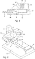
- FIG. 3 depicts an embodiment of such an apparatus.
- This apparatus comprises a base plate 10 onto which a column 11 is solidly connected.
- the base plate 10 and the column 11 together form a frame.
- a yoke 12 is slidably connected, to drive the yoke in the vertical direction drive means not depicted in the drawing, comprising and electric motor, and possibly a rack and pinion system may be provided.
- the yoke 12 comprises two clamps 13A, 13B connected symmetrically to the yoke 12.
- the clamps 13 are adapted to clamp the two opposite edges of the flexible mould 3.
- a support 14 is provided for supporting and fixating the substrate to be provided of a relief layer.
- This support may be firmly connected to the base plate 10, but in the embodiment depicted, it is slidably connected to a rail 15, allowing the support to be transferred between the position under the mould 3 and a second position 16 in which the substrate may be provided with the liquid layer or in which the substrate may be provided complete with a liquid layer. Further, the substrate 2, complete with the cured layer 3 can be removed from said second position 16, to allow further processing.
- a LED 17 functioning as a radiation source is provided on the yoke 12. The Led 17 may however also be located in another position adapted to let the radiation emitted by the LED to reach the liquid layer to be cured.
- connection between the clamps 13 and the yoke 12 can be embodied in different ways.
- the connection may be fixed, so that the clamps 13 are fixed to the yoke 12.
- This embodiment is only applicable if the mould 3 is substantially longer than the length of the substrate 2, to allow the flexibility of the mould 3 to cater for the variations in shape of the mould 3, such as the rate of sagging.
- the clamps 13 are connected slidably with a horizontal component to the yoke 12 to allow variation of the distance between the clamps 13. This variation caters for the decreasing rate of sagging of the mould 2 when the yoke 12 is lowered and the contact surface area between the mould 3 and the liquid layer 2 increases.
- the horizontal movement of the clamps 13 is preferably coupled to the vertical movement of the yoke 12 .
- clamps 13 rotatably to the yoke 12, possibly in combination with the slidable connection between the clamps 13 and the yoke 12. This feature allows to cater for the decreasing angle at the clamps 13 between the mould 3 and the horizontal when the mould 12 covers an increasing area of the fluid layer 2. It is possible to have the clamps 13 freely rotatable, but it is preferred that the rotation of the clamps 13 is preferably coupled to the vertical movement of the yoke 12.
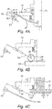
- Figures 4A-4E show several different embodiments of the connection between the clamps and the yoke. It is noted that only a half of a yoke 12 is depicted in drawing. In the embodiment depicted in figure 4A a carriage 18 has been slidably mounted to the yoke 12 and the clamp 13 is rotatably connected to the carriage 18 by a shaft 19, thus allowing for both translation and rotation of the clamp 13. In the shaft 19 a through going slot 20 has been provided and a curved leaf spring 21 fixed to the column extends through the slot 20.
- the embodiment depicted in figure 4B comprises a rack rail 23 extending over the base plate 10 and a gear 24 of which the teeth engage the rack rail 23.
- a first end of an arm 26 is rigidly connected with the gear 24, so that the rotation of the arm 26 causes rotation of the gear 24 and, as caused by the rack rail 23, translation of the gear 24 and of the first end of the arm 26.
- a slot 25 is located in the arm and a pin 25A is connected to the yoke 12 and extends through the slot 25.
- the clamp 13 is fixed to the second end of the arm 26. Vertical movement of the yoke 12 results in both a rotation and translation of the arm 26 relative to the base. This results in an involute movement of the clamp 13.
- FIG. 4C A simpler embodiment is depicted in figure 4C ; one end of an arm 27 is rotatably connected to the base plate 10 or the column 11.
- a slot 28 is provided in the arm 27 and a pin 29 connected to the yoke 12 extends into the slot 28, allowing relative translation and rotation of the arm 27 relative to the yoke 12.
- the clamp 13 is fixed to the second end of the arm 27. Vertical movement of the yoke 12 results in both rotation of the arm 27, wherein the second end of the arm and hence the clamp 13 describes a rotation and a translation.
- FIG. 4D An embodiment allowing more freedom in design is depicted in figure 4D .
- This embodiment comprises a plate 30 extending in vertical direction perpendicular to the rail 15 and wherein two slots 31, 32 have been provided.
- the slots 31,32 have a curved shape and they both extend with a horizontal and a vertical component.
- a carriage 33 is attached to the clamp 13 and two pins 34, 35 extend from the carriage 33 through the slots 31.
- the shape of the slots 31, 32 determine the path of the carriage 33 and of the clamp 13.
- One of the pins 34 extends also into a horizontal slot 36 provided in the yoke 12. Vertical movement of the yoke 12 results in vertical movement of the pin 34.
- the pin 34 As the pin 34 also extends through the slot 31 which has a horizontal component, the pin 34 also moves in horizontal direction, also moving the other pin 35, of which the movement is determined by the other slot 32. Now that the path of the movement of the both pins 34, 35 is determined, the path of the carriage 33 and the clamp 13 connected thereto is determined, both in translation and rotation.
- FIG 4E shows an embodiment wherein the both the translation and the rotation of the clamp can be freely determined.
- each comprising one column 11 this embodiment comprises two columns 40, 41, one for each of the clamps 13 and only one of the columns 40 is depicted.
- the column 40 is mounted on a carriage 42, which is movable over a rail 44 mounted on the base plate.
- a controllable motor 46 is provided to drive the carriage over the rail 44.
- a yoke 48 is mounted movable in vertical direction over the column 40 and a controllable motor 50 is provided to drive the yoke 48 over the column 40.
- the clamp 13 is mounted rotatable relative to the yoke 48, and a controllable motor 52 is provided to drive the clamp 13. It will be clear that a similar, preferably mirrored structure is present to control the other clamp 13. By controlling the motors 46, 50 and 52, the position in two directions and the angle of the clamp is controllable.
- FIG. 5 An embodiment of the clamps is shown in figure 5 .
- the embodiment of the clamp 13 depicted in figure 5 comprises a fixed part 60 and a moveable part 61 connected to the fixed part 60 by a shaft 62, allowing the moveable part 61 to move relative to the fixed part 60.
- On the moveable part 61 a pressing member 63 has been mounted, into which a cavity 64 has been provided.
- the cavity comprises a continuation 65 having a smaller diameter and extending through the moveable part 61.
- a screw 66 extends through the cavity 64 and its continuation 65 and it is screwed into the fixed part of the clamp 13.
- a helical spring 67 is pressed between the bottom of the cavity and the head of the screw 66, pressing the pressing member 63 and hence the moveable part 61 of the clamp to the fixed part thereof, thus providing a controllable pressing force for pressing the mould 3 between the two parts 60, 61 of the clamp.
- a piece of sanding paper 68 is glued to the fixed part 60 of the clamp 13.
- other friction materials may be used as well.
- Figure 6 depicts an apparatus similar to that depicted in figure 3 , but wherein the connection between the clamps 13 to the yoke 12 has been modified to allow rotation or tilt of the clamps 13 around an axis extending in the longitudinal direction of the mould 3. As the mould 3 extends between the clamps, the axis extends between the centres of the clamps 13. To control the tilt, two electric motors 70 are connected to the ends of the yoke 12 and a shaft 71 extends from each of the motors 70 to the clamps 13. The clamps 13 are fixed to the shafts 71. The motors 70 are controlled such that the motors rotate simultaneously.
- Tilting of the clamps 13 makes the mould 3 tilt such that, when the assembly of the yoke 12, the motors 70, the clamps 13 and the mould 3 lowers, the mould 3 initially touches the substrate 1, or rather the liquid layer 2 on the substrate 1 in a point, rather than over a line, as is the case in the situation depicted in figure 3 .
- the initial tilt of the mould 3 is to be reversed, preferably simultaneously with the lowering of the mould 3, to allow the mould to extend over the full surface area of the liquid layer 2 of the substrate 1.
Landscapes
- Physics & Mathematics (AREA)
- Engineering & Computer Science (AREA)
- Health & Medical Sciences (AREA)
- Mechanical Engineering (AREA)
- Electromagnetism (AREA)
- Toxicology (AREA)
- Oral & Maxillofacial Surgery (AREA)
- Thermal Sciences (AREA)
- General Physics & Mathematics (AREA)
- Quality & Reliability (AREA)
- Coating Apparatus (AREA)
Abstract
Description
- The present invention relates to a method for applying a layer having a relief on a flat face of a substrate.
- In some situations there is a desire to provide a layer with a relief on a substrate. This may be the case in the provision of a frosted layer on clear glass or the provision of optical structures on printed matter to obtain visual effects. Although voluminous substrates are not excluded, it is envisaged that the layer having a relief is applied on a thin substrate, such as a card or a piece of paper. The substrate may be laminated but it may also be formed by a single layer. The substrate is preferably, but not necessarily formed by a security document such as an identity card, a personalized card in a passport or a credit card.
- From the prior art a method is known, comprising the steps of securing the substrate with the surface onto which the relief is to be provided on top, applying a layer of a curable liquid on the upper surface of the substrate, bringing a mould having a counter relief into contact with at least a part of the upper surface of the liquid layer, curing the liquid layer while the mould is in contact with the curable liquid and separating the mould from the substrate.
- This prior art method makes use of a rigid mould. This leads to the disadvantage that when the mould is brought into contact with the liquid on the substrate, air inclusions may develop, leading to bubbles in the liquid and to later to irregularities in the relief after curing. Further there the liquid may be pushed away from the substrate by the mould.
- To avoid these disadvantages, another prior art method provides a method of the kind referred above wherein the mould is still rigid, but wherein the substrate is bent. Although possible if the substrate can be bended, this method has the disadvantage that, after making contact with the mould, the substrate must be brought back to its original flat shape before the curing can take place, requiring complicated machinery and likely leading to deformation of the relief. The substrate can be brought back to its original flat shape after curing, but this would lead to deformation and breakage of the relief layer.
- The present invention aims to avoid these disadvantages, by providing such a method wherein initially the mould is brought into contact with the upper surface of the liquid layer in bent position while the substrate is kept flat and subsequently the mould is brought into contact with an increasing surface area, keeping the mould in a bent position until the complete liquid layer is in contact with the mould and at least the part of the mould in contact with the liquid layer being flat, keeping the substrate flat. The bent mould is kept in a form wherein the profile of the mould is a catenary. Upon contact of the mould with the surface, the profile of the mould is kept to be the same catenary. This is achieved by moving the ends of the mould which are guided by a manipulator not only in a vertical direction but also in a horizontal direction in such a way that the mould not being in contact with the surface of the liquid layer has the profile of the same catenary than before. By this guidance, the profile of the mould not being in contact with the surface can be kept as the same catenary over the whole process of bringing the mould into contact with the surface. At the end, the whole mould is in contact with the surface and after that there is no catenary profile but the mould is horizontal to the surface.
- A catenary is the curve that an idealized hanging chain or cable assumes under its own weight when supported only at its ends. The curve has a U-like shape, superficially similar in appearance to a parabola, but it is not a parabola: it is a (scaled, rotated) graph of the hyperbolic cosine. Before the mould is in contact with the surface, it has a profile of a catenary. During the lowering process on the surface, this profile is kept by moving the ends of the mould along a curve that constrains the remaining profile of the mould not being in contact with the surface to that catenary of the free hanging mould with no contact with the surface. In practice, this might not be achieved mathematically precisely, but the method follows this theoretical curve approximately.
- This method provides the gradual bringing into contact of the mould with the fluid layer on the substrate, avoiding any air inclusions. Further it avoids the urging of the liquid away from the substrate, as the process is gradual. Finally it avoids deformation of the relief layer either in liquid or in cured form with the associated problems.
- If the substrate is a security document, the substrate is provided with a print, often with a personalized section. The relief layer needs to be transparent for visible light to allow the print of the substrate to be viewed. For further enhancement of the security it is preferred that the relief layer itself is also provided with a print. This extra print on the relief layer may cooperate with the print under the relief layer to give a visible effect, possibly in cooperation with the relief layer. The relief layer may have properties leading to a visible effect such as a lenticular effect. All these features enhance the security, that is increase the difficulty of copying and falsification.
- It is noted that in the above paragraph the mould is brought to the substrate; it will be clear that it is also possible to move the substrate to mould or to move both the substrate and the mould to each other. Any amendments to the apparatus required to perform these kinematic variations will be clear for a skilled man.
- Further the present invention provides an apparatus for applying a layer having a relief on a flat surface of a substrate, the apparatus comprising a frame, securing means connected to the frame and adapted to secure the substrate with the surface of the substrate onto which the relief is to be applied, on top, a flat mould carrying a counter relief, a radiation source adapted to emit radiation curing the liquid applied in a layer on the substrate to a solid layer having a relief, wherein the mould is flexible and that the flexible mould has a profile of a catenary before being brought in contact with the upper surface of the liquid layer and the apparatus comprises a manipulator connected to the frame, the manipulator being adapted to initially bring the mould into contact with the upper surface of the liquid layer and to subsequently bring the mould into contact over an adjacent upper surface area of the liquid layer until the complete liquid layer is in contact with the mould wherein the mould is kept bent until the complete liquid layer is in contact with the mould and at least the part of the mould in contact with the liquid layer is flat, wherein the manipulator is adapted to guide the mould such that the profile of the mould not being in contact with the surface is kept as the same catenary over the whole process of bringing the mould into contact with the surface. With this guidance of the manipulators along a curve which is not only vertically moving downwards but at the same time moving horizontally outwards to a degree that the profile of the mould can be kept to follow the same catenary, constant conditions at the line of contact between the mould and the surface can be achieved.
- For most mould materials, such as silicone, the flexibility of the mould allows bending of the mould over a single axis only. Assuming the axis of the bent of the mould to be parallel to the upper surface of the substrate, the mould is initially brought into contact with the substrate over a line.
- However it is also possible that the mould is initially brought into contact with the substrate in a point. This requires the axis of the bent of mould being tilted relative to the surface of the substrate during initial contact. Having such a tilted axis of bending prevents later contact of the mould over the complete surface of the substrate with the flat mould. To make contact over the full surface area of the substrate, the mould needs to be moved to a position with its axis of bending parallel to the surface of the substrate.
- This embodiment also provides an apparatus wherein the clamps are connected to the yoke rotatably over an axis extending substantially between the centres of the clamps.
- According to an embodiment, the initial contact location coincides with one side of the upper surface of the substrate and that subsequently the mould is brought into contact with the further upper surface area of the liquid layer in a single direction. Herein the complete surface of the liquid must be covered in a single process, but which requires complicated manipulation equipment and which requires some time.
- It is however preferred that the initial contact location is on a distance from the sides of the upper surface of the substrate and that subsequently the mould is brought into contact with the further surface area of the liquid layer in two opposite directions. In this process the two areas at either side of the initial contact are covered simultaneously, hence requiring less time. Further the process is preferably executed symmetrically, making the manipulator relatively simple as the flexible mould can be gripped at its ends, allowing the mould to sag so that the lowest part of the mould contacts the liquid initially.
- According to another preferred embodiment the liquid layer applied is transparent for curing radiation when liquid and transparent for visible light when cured. The transparency in the liquid state allows to reach the complete layer with the radiation. Although it is possible to make the resulting cured layer opaque and coloured, it is preferred that the cured layer is transparent for visible light. This allows to provide optical features in the transparent layer such as small lenses etc.
- The same feature provides an apparatus of the kind referred to above, wherein the mould is transparent for radiation emitted by the radiation source. Further it is noted that it is also possible to irradiate the liquid layer from the underside that is through the substrate. It will be clear that this would require the transparency of the substrate for the radiation curing the liquid.
- As explained earlier the most attractive way of bringing the mould into contact with the liquid, is to make contact between the mould and the liquid in an intermediate position and to gradually increase the surface area of the contact in both directions. This is made easier when the manipulator comprises two clamps, each being adapted to grip one of two opposite sides of the mould and each being connected with a yoke moveable in a vertical direction and comprising driving means for driving the vertical movement of the yoke. Then the distance between the clamps is smaller than the length of the mould so that the mould sags and the lowest part of the mould contacts the liquid first and the contact face is increased when the clamps are lowered further.
- To allow sagging of the mould, it is preferred when at least one of the clamps is mounted on the yoke rotatable around an axis extending parallel to the contact line and that the apparatus comprises rotation coupling means adapted to couple the rotation movement of the at least one clamp relative to the yoke to the vertical movement of the yoke. This feature allows to have the mould extend downwardly sloping from the clamps, wherein the slope may change during the lowering of the mould as caused by the movement of the separation between the increasing part of the mould in contact with the liquid and the decreasing part of the mould, not in contact with the liquid.
- For the same reason it is preferred when at least one of the clamps is mounted on the yoke translatable in horizontal direction and the apparatus comprises coupling means adapted to couple the horizontal movement of the at least one clamp relative to the yoke.
- The same effect is reached when the clamps are symmetrically arranged relative to the centre of the fixation means.
- In a constructive simple embodiment the rotation coupling means comprise an arm of which one end is rotatably connected to the frame and the other end is solidly connected to the clamp and wherein the yoke comprises a part slidably connected to the arm.
- Although other means of temporary fixation are not excluded, it is preferred when the securing means for fixation of the substrate, comprise a carrier provided of switchable vacuum securing means.
- Preferably the carrier is moveable in substantial horizontal direction on a rail. This feature allows to transport the substrate with the liquid from a station wherein the liquid is applied to the substrate to the apparatus according to the invention and to transport the substrate with the cured liquid away for further processing.
- In another constructive simple embodiment the radiation source is formed by a LED mounted on the yoke. The mounting on the yoke, makes the distance between the radiation source and the liquid to be cured small, allowing to use a small radiation source such as a LED.
- Of course the apparatus may accept substrates already provided with a layer of liquid to be cured. It is however preferred when the apparatus comprises an applicator for application of the layer of liquid on the substrate.
- To allow an easy exchange of moulds it is preferred that the clamps each comprise a pair of jaws mutually moveable between an active and an inactive position and a spring adapted to urge the jaws to towards one another in the active position, both jaws being adapted to pinch opposite strips of the mould.
- In many cases the flexibility of the mould combined with the ability to contain a relief, can be obtained with materials possibly having the structure of a gel, making it troublesome to be securely gripped. To allow a sure gripping of opposite ends of the mould, it is preferred when at least one of the jaws on its pinching surface comprises an friction layer, such as a layer of sanding paper. Silicone is a good example of a material to be used for the mould, although other materials, such as other polymers, are not excluded.
- Subsequently the present invention will be elucidated with the help of the following drawings, wherein depict:
-
Figures 1A-1C : cross sectional diagrams depicting three phases in the process of applying the mould to the liquid layer according to a first embodiment; -
Figures 2A-2C : diagrams depicting three phases in the process of applying the mould to the liquid layer according to a second, alternative embodiment; -
Figure 3 : a diagrammatic perspective view of an apparatus adapted to perform a method according to the second embodiment; -
Figures 4A-4E : diagrams showing different constructional possibilities of the second embodiment; -
Figure 5 : a cross section view of a clamp to be used in the apparatus according to the invention; and -
Figure 6 : a view similar tofigure 3 , depicting an alternative embodiment. - The present invention relates to the application of a relief layer on a substrate such as a plastic card, like a credit card. The method according to the invention comprises - assuming the presence of a card with a layer of curable liquid - the application of a mound on the liquid, wherein the mould has a relief which is the negative of the relief to be applied to the layer. The invention provides the gradual bringing into contact of the mould with the layer avoiding the inclusion of air between the mould and the liquid. After the mould has been brought into contact with the liquid, the liquid is cured by radiation. The gradual contact between the mould and the liquid requires a flexible or bendable mould. This mould is initially brought into contact with the liquid on the substrate in a single line, and
figure 1 depicts a first embodiment in cross section. -
Figures 1A-C depict acard 1, acting as a substrate onto which athin layer 2 of curable liquid has been provided. Infigure 1A anedge 4 of amould 3 is brought into contact with theliquid layer 2. This figure shows that the part of themould 3 in contact with the liquid extends substantially parallel to the surface of the liquid as a preparation for the next step. Infigure 1B roughly half of the surface of theliquid layer 2 is covered by themould 3. Again thepart 3a of themould 3 in contact with theliquid layer 2 extends parallel to the surface of said layer. Due to the flexibility of the mould, the angle of thepart 3b of the mould not in contact with the liquid 2 with the horizontal increases gradually from zero, as caused by the flexibility of themould 3. In the final situation, depicted infigure 1C , thecomplete mould 3 extends parallel to the surface of theliquid layer 2. It is however also possible that only the part of the mould extending parallel to the substrate is flat and that the part of the mould not in contact with the substrate is curved, but the tangent to the curve at the border of the substrate is parallel to the substrate. - It can be seen in a comparison from
Fig. 1A and 1B that the end of the mould being lowered does not only follow a vertical downward movement but that at the same time the end moves horizontally outwards. Thus, the profile of the mould can keep the same catenary and thus the conditions at the line of contact are the same during the whole process of lowering the mould. - In the embodiment discussed above, it is assumed that the substrate is substantially rectangular, and that the initial contact line between the
edge 4 of the mould coincides with an edge of the liquid layer on the substrate. It is however also possible that thesubstrate 1 has another, non-rectangular shape and or that the initial contact line is formed by a single point on a corner of thesubstrate 1. - Another possibility is represented in
figure 2 . Herein the middle of theflexible mould 3 is initially brought into contact with aline 4 traversing the surface area of theliquid layer 2. This situation is represented infigure 2A . This embodiment is preferably although not necessarily symmetrical. The process of bringing themould 3 into contact with theliquid layer 2 is substantially equivalent to that described with the help of thefigure 1 , although performed at both sides of the initial contact line. Again theparts figures 2A and 2C one can see the curve that the extreme of the left part of themould 3b describes. Infigure 2A this extreme point of the part of themould 3b is at point S. When lowering the mould onto the surface, this extreme point travels to point T as shown infigure 2B . By this guidance, the profile of the mould not being in contact with the surface keeps the form of a catenary like the catenary of the mould infigure 2A . Following through until the final position as shown infigure 2C , the extreme point is in position U. Here, the mould is parallel to the surface of theliquid layer 2. Infigure 2C the whole curve from points S to U via T can be seen and this curve of the extreme point of the mould allows for the mould not being in contact with the surface to keep the profile of a catenary with the same parameters than the catenary of the free hanging mould. When the edges of themould 3 are lowered, the surface area of thepart 3a of themould 3 being into contact with theliquid layer 2 increases, as is represented infigure 3b . This process is continued until the full surface area of theliquid layer 2 is covered by themould 3, as is represented infigure 2C . - The above two figures only relate to the actual process. An apparatus is required to allow the process to be performed.
Figure 3 depicts an embodiment of such an apparatus. This apparatus comprises abase plate 10 onto which acolumn 11 is solidly connected. Thebase plate 10 and thecolumn 11 together form a frame. On the column 11 ayoke 12 is slidably connected, to drive the yoke in the vertical direction drive means not depicted in the drawing, comprising and electric motor, and possibly a rack and pinion system may be provided. Theyoke 12 comprises twoclamps yoke 12. Theclamps 13 are adapted to clamp the two opposite edges of theflexible mould 3. Under the position between the clamps asupport 14 is provided for supporting and fixating the substrate to be provided of a relief layer. This support may be firmly connected to thebase plate 10, but in the embodiment depicted, it is slidably connected to arail 15, allowing the support to be transferred between the position under themould 3 and asecond position 16 in which the substrate may be provided with the liquid layer or in which the substrate may be provided complete with a liquid layer. Further, thesubstrate 2, complete with the curedlayer 3 can be removed from saidsecond position 16, to allow further processing. Finally aLED 17 functioning as a radiation source is provided on theyoke 12. TheLed 17 may however also be located in another position adapted to let the radiation emitted by the LED to reach the liquid layer to be cured. - The connection between the
clamps 13 and theyoke 12 can be embodied in different ways. The connection may be fixed, so that theclamps 13 are fixed to theyoke 12. This embodiment is only applicable if themould 3 is substantially longer than the length of thesubstrate 2, to allow the flexibility of themould 3 to cater for the variations in shape of themould 3, such as the rate of sagging. - It is however preferred that the
clamps 13 are connected slidably with a horizontal component to theyoke 12 to allow variation of the distance between theclamps 13. This variation caters for the decreasing rate of sagging of themould 2 when theyoke 12 is lowered and the contact surface area between themould 3 and theliquid layer 2 increases. The horizontal movement of theclamps 13 is preferably coupled to the vertical movement of theyoke 12 . - It is also preferred to connect the
clamps 13 rotatably to theyoke 12, possibly in combination with the slidable connection between theclamps 13 and theyoke 12. This feature allows to cater for the decreasing angle at theclamps 13 between themould 3 and the horizontal when themould 12 covers an increasing area of thefluid layer 2. It is possible to have theclamps 13 freely rotatable, but it is preferred that the rotation of theclamps 13 is preferably coupled to the vertical movement of theyoke 12. -
Figures 4A-4E show several different embodiments of the connection between the clamps and the yoke. It is noted that only a half of ayoke 12 is depicted in drawing.
In the embodiment depicted infigure 4A acarriage 18 has been slidably mounted to theyoke 12 and theclamp 13 is rotatably connected to thecarriage 18 by ashaft 19, thus allowing for both translation and rotation of theclamp 13. In the shaft 19 a through goingslot 20 has been provided and acurved leaf spring 21 fixed to the column extends through theslot 20. The vertical movement of theyoke 12 relative to thecolumn 11 results in a relative movement of theshaft 19 relative to theleaf spring 21 and the curved shape of theleaf spring 21 results in both rotation and translation of theshaft 19 and theclamp 13 connected to theshaft 19. Your attention is drawn to the fact that only one half of the apparatus is depicted in this figure and that the complete apparatus comprises a second mirrored half. Further it is possible that the complete apparatus comprises asingle leaf spring 21 with double length extending to both sides of thecolumn 11. - The embodiment depicted in
figure 4B comprises arack rail 23 extending over thebase plate 10 and agear 24 of which the teeth engage therack rail 23. A first end of anarm 26 is rigidly connected with thegear 24, so that the rotation of thearm 26 causes rotation of thegear 24 and, as caused by therack rail 23, translation of thegear 24 and of the first end of thearm 26. Aslot 25 is located in the arm and a pin 25A is connected to theyoke 12 and extends through theslot 25. Theclamp 13 is fixed to the second end of thearm 26. Vertical movement of theyoke 12 results in both a rotation and translation of thearm 26 relative to the base. This results in an involute movement of theclamp 13. - A simpler embodiment is depicted in
figure 4C ; one end of anarm 27 is rotatably connected to thebase plate 10 or thecolumn 11. Aslot 28 is provided in thearm 27 and a pin 29 connected to theyoke 12 extends into theslot 28, allowing relative translation and rotation of thearm 27 relative to theyoke 12. Theclamp 13 is fixed to the second end of thearm 27. Vertical movement of theyoke 12 results in both rotation of thearm 27, wherein the second end of the arm and hence theclamp 13 describes a rotation and a translation. - An embodiment allowing more freedom in design is depicted in
figure 4D . This embodiment comprises aplate 30 extending in vertical direction perpendicular to therail 15 and wherein twoslots slots carriage 33 is attached to theclamp 13 and twopins carriage 33 through theslots 31. The shape of theslots carriage 33 and of theclamp 13. One of thepins 34 extends also into ahorizontal slot 36 provided in theyoke 12. Vertical movement of theyoke 12 results in vertical movement of thepin 34. As thepin 34 also extends through theslot 31 which has a horizontal component, thepin 34 also moves in horizontal direction, also moving theother pin 35, of which the movement is determined by theother slot 32. Now that the path of the movement of the bothpins carriage 33 and theclamp 13 connected thereto is determined, both in translation and rotation. - Finally
figure 4E shows an embodiment wherein the both the translation and the rotation of the clamp can be freely determined. Contrary to the embodiments discussed hitherto, each comprising onecolumn 11 this embodiment comprises twocolumns 40, 41, one for each of theclamps 13 and only one of thecolumns 40 is depicted. Thecolumn 40 is mounted on acarriage 42, which is movable over arail 44 mounted on the base plate. Acontrollable motor 46 is provided to drive the carriage over therail 44. Ayoke 48 is mounted movable in vertical direction over thecolumn 40 and acontrollable motor 50 is provided to drive theyoke 48 over thecolumn 40. Theclamp 13 is mounted rotatable relative to theyoke 48, and acontrollable motor 52 is provided to drive theclamp 13. It will be clear that a similar, preferably mirrored structure is present to control theother clamp 13. By controlling themotors - An embodiment of the clamps is shown in
figure 5 . As stated before themould 3 has to be flexible, and at the same time to have a certain thickness to contain a counter relief, making the clamping of such amould 3 cumbersome. The embodiment of theclamp 13 depicted infigure 5 comprises afixed part 60 and amoveable part 61 connected to the fixedpart 60 by ashaft 62, allowing themoveable part 61 to move relative to the fixedpart 60. On the moveable part 61 a pressingmember 63 has been mounted, into which acavity 64 has been provided. The cavity comprises acontinuation 65 having a smaller diameter and extending through themoveable part 61. Ascrew 66 extends through thecavity 64 and itscontinuation 65 and it is screwed into the fixed part of theclamp 13. Ahelical spring 67 is pressed between the bottom of the cavity and the head of thescrew 66, pressing thepressing member 63 and hence themoveable part 61 of the clamp to the fixed part thereof, thus providing a controllable pressing force for pressing themould 3 between the twoparts clamp 13 and themould 2, a piece of sandingpaper 68 is glued to the fixedpart 60 of theclamp 13. However other friction materials may be used as well. -
Figure 6 depicts an apparatus similar to that depicted infigure 3 , but wherein the connection between theclamps 13 to theyoke 12 has been modified to allow rotation or tilt of theclamps 13 around an axis extending in the longitudinal direction of themould 3. As themould 3 extends between the clamps, the axis extends between the centres of theclamps 13. To control the tilt, two electric motors 70 are connected to the ends of theyoke 12 and a shaft 71 extends from each of the motors 70 to theclamps 13. Theclamps 13 are fixed to the shafts 71. The motors 70 are controlled such that the motors rotate simultaneously. Tilting of theclamps 13 makes themould 3 tilt such that, when the assembly of theyoke 12, the motors 70, theclamps 13 and themould 3 lowers, themould 3 initially touches thesubstrate 1, or rather theliquid layer 2 on thesubstrate 1 in a point, rather than over a line, as is the case in the situation depicted infigure 3 . When the assembly is lowered further, the initial tilt of themould 3 is to be reversed, preferably simultaneously with the lowering of themould 3, to allow the mould to extend over the full surface area of theliquid layer 2 of thesubstrate 1. - Especially, though not exclusively it appears to be is attractive to apply the kinematic variations mentioned before in this embodiment, for instance by providing a lift for the block carrying the substrate.
- The above description elucidates some embodiments of the invention, but the invention is not restricted to these embodiments, of which different features may be combined; rather the scope of the invention is determined by the claims.
Claims (20)
- Method for applying a layer having a relief on a flat surface of a substrate, the method comprising the following steps:- securing the substrate with the surface onto which the relief is to be provided on top;- applying a layer of a curable liquid on the upper surface of the substrate;- bringing a mould having a relief being the negative of the relief to be provided on the substrate, into contact with at least a part of the upper surface of the liquid layer;- curing the liquid layer while the mould is in contact with the curable liquid; and- separating the mould from the substrate,characterized in that- initially the mould is brought into contact with the upper surface of the liquid layer in a bent position while the substrate is kept flat wherein the profile of the mould is a catenary; and- subsequently the mould is brought into contact over an increasing surface area keeping the mould in a bent position until the complete liquid layer is in contact with the mould and at least the part of the mould in contact with the liquid layer is flat, keeping the substrate flat, wherein the profile of the mould not being in contact with the surface is kept as the same catenary over the whole process of bringing the mould into contact with the surface.
- Method as claimed in claim 1, characterized in that the mould is initially brought into contact with the liquid layer on the substrate over a line.
- Method as claimed in claim 1, characterized in that the mould is initially brought into contact with the liquid layer on the substrate in a point.
- Method as claimed in claim 1, 2 or 3, characterized in that the initial contact location coincides with a side of the upper surface of the substrate and that subsequently the mould is brought into contact with the further upper surface area of the liquid layer in a single direction.
- Method as claimed in claim 1, 2 or 3, characterized in that the initial contact location is located on a distance from the sides of the upper surface of the substrate and that subsequently the mould is brought into contact with the further surface area of the liquid layer in two opposite directions.
- Method as claimed in any of the claims 1-5, characterized in that the liquid layer applied is substantially transparent for curing radiation when liquid and transparent for visible light when cured.
- Apparatus for applying a layer having a relief on a flat surface of a substrate, the apparatus comprising:- a frame;- fixation means connected to the frame and adapted to fixate the substrate with the surface of the substrate onto which the relief is to be applied on top;- a mould carrying a counter relief;- a radiation source adapted to emit radiation curing the liquid applied in a layer on the substrate,characterized in that the mould is flexible and that the flexible mould has a profile of a catenary before being brought in contact with the upper surface of the liquid layer and that the apparatus comprises a manipulator connected to the frame, the manipulator being adapted to initially bring the bent mould into contact with the upper surface of the liquid layer and to subsequently bring the mould into contact over an adjacent upper surface area of the liquid layer until the complete liquid layer is in contact with the mould wherein the mould is kept bent until the complete liquid layer is in contact with the mould and at least the part of the mould in contact with the liquid layer is flat, wherein the manipulator is adapted to guide the mould such that the profile of the mould not being in contact with the surface is kept as the same catenary over the whole process of bringing the mould into contact with the surface.
- Apparatus as claimed in claim 7, characterized in that the mould is substantially transparent for radiation emitted by the radiation source.
- Apparatus as claimed in claim 7 or 8, characterized in that the manipulator comprises two clamps, each being adapted to grip one of two opposite sides of the mould and each being connected with a yoke moveable in a vertical direction and comprising driving means for driving the vertical movement of the yoke.
- Apparatus as claimed in claim 9, characterized in that the clamps are connected to the yoke rotatable over an axis extending between the centres of the clamps.
- Apparatus as claimed in claim 9 or 10. characterized in that at least one of the clamps is mounted on the yoke rotatable around an axis extending parallel to the contact line and that the apparatus comprises rotation coupling means adapted to couple the rotation movement of the at least one clamp relative to the yoke to the vertical movement of the yoke.
- Apparatus as claimed in claim 9 or 10, characterized in that at least one of the clamps is mounted on the yoke translatable in horizontal direction and that the apparatus comprises coupling means adapted to couple the horizontal movement of the at least one clamp relative to the yoke.
- Apparatus as claimed in claim 10, 11 or 12, characterized in that the clamps are arranged symmetrically relative to the centre of the fixation means.
- Apparatus as claimed in claim 13, characterized in that the rotation coupling means comprise:- an arm of which one end is rotatably connected to the frame and the other end is solidly connected to the clamp; and- the yoke comprising a part slidably connected to the arm.
- Apparatus as claimed in any of the claims 7-14, characterized in that the fixation means for fixation of the substrate, comprise a block provided with switchable vacuum fixation means.
- Apparatus as claimed in claim 15, characterized in that the block is moveable in substantial horizontal direction on a rail.
- Apparatus as claimed in any of the claims 7-16, characterized in that the radiation source is formed by a LED mounted on the yoke.
- Apparatus as claimed in any of the claims 7-17, characterized in that the apparatus comprises an applicator for application of the layer of liquid on the substrate.
- Apparatus as claimed in any of the claims 7-18, characterized in that the clamps each comprise a pair of jaws mutually moveable between an active and an inactive position and a spring adapted to urge the jaws towards one another in the active position, both jaws being adapted to pinch opposite strips of the mould.
- Apparatus as claimed in claim 19, characterized in that at least one of the jaws on its pinching surface comprises an friction layer, such as a layer of sanding paper.
Priority Applications (1)
| Application Number | Priority Date | Filing Date | Title |
|---|---|---|---|
| US15/485,810 US10611078B2 (en) | 2016-04-12 | 2017-04-12 | Method and apparatus for applying a layer having a relief on a flat face of a substrate |
Applications Claiming Priority (1)
| Application Number | Priority Date | Filing Date | Title |
|---|---|---|---|
| NL2016593A NL2016593B1 (en) | 2016-04-12 | 2016-04-12 | Method and apparatus for applying a layer having a relief on a flat face of a substrate. |
Publications (2)
| Publication Number | Publication Date |
|---|---|
| EP3235626A1 true EP3235626A1 (en) | 2017-10-25 |
| EP3235626B1 EP3235626B1 (en) | 2022-07-06 |
Family
ID=56097251
Family Applications (1)
| Application Number | Title | Priority Date | Filing Date |
|---|---|---|---|
| EP17166251.3A Active EP3235626B1 (en) | 2016-04-12 | 2017-04-12 | Method and apparatus for applying a layer having a relief on a flat face of a substrate |
Country Status (3)
| Country | Link |
|---|---|
| US (1) | US10611078B2 (en) |
| EP (1) | EP3235626B1 (en) |
| NL (1) | NL2016593B1 (en) |
Cited By (1)
| Publication number | Priority date | Publication date | Assignee | Title |
|---|---|---|---|---|
| US10611078B2 (en) | 2016-04-12 | 2020-04-07 | Iai Industrial Systems B.V. | Method and apparatus for applying a layer having a relief on a flat face of a substrate |
Citations (4)
| Publication number | Priority date | Publication date | Assignee | Title |
|---|---|---|---|---|
| US20100255139A1 (en) * | 2009-04-03 | 2010-10-07 | Ryuta Washiya | Micropattern transfer stamper and micropattern transfer device |
| US20100303947A1 (en) * | 2009-06-02 | 2010-12-02 | Hitachi High-Technologies Corporation | Fine-structure transfer apparatus |
| US8163222B2 (en) * | 2009-02-20 | 2012-04-24 | Api Group Plc | Machine head for production of a surface relief |
| US20150021798A1 (en) * | 2012-03-22 | 2015-01-22 | Toyo Seikan Group Holdings, Ltd. | Method of molding a thermoplastic resin article and apparatus for molding same |
Family Cites Families (8)
| Publication number | Priority date | Publication date | Assignee | Title |
|---|---|---|---|---|
| NL177721B (en) * | 1977-03-14 | 1985-06-03 | Philips Nv | METHOD FOR MANUFACTURING A PLASTIC INFORMATION CARRIER WITH LAYERED STRUCTURE AND AN APPARATUS FOR CARRYING OUT THE METHOD |
| US5500067A (en) * | 1991-10-01 | 1996-03-19 | Jenkner; Brian D. | Apparatus and methods for forming, filling and sealing fluid filled cavities |
| US5804017A (en) * | 1995-07-27 | 1998-09-08 | Imation Corp. | Method and apparatus for making an optical information record |
| US7019819B2 (en) * | 2002-11-13 | 2006-03-28 | Molecular Imprints, Inc. | Chucking system for modulating shapes of substrates |
| US7641840B2 (en) * | 2002-11-13 | 2010-01-05 | Molecular Imprints, Inc. | Method for expelling gas positioned between a substrate and a mold |
| US20060065989A1 (en) * | 2004-09-29 | 2006-03-30 | Thad Druffel | Lens forming systems and methods |
| US8047252B2 (en) * | 2008-12-19 | 2011-11-01 | United Technologies Corporation | Modular component pressure application fixture |
| NL2016593B1 (en) | 2016-04-12 | 2017-11-01 | Iai Ind Systems B V | Method and apparatus for applying a layer having a relief on a flat face of a substrate. |
-
2016
- 2016-04-12 NL NL2016593A patent/NL2016593B1/en not_active IP Right Cessation
-
2017
- 2017-04-12 US US15/485,810 patent/US10611078B2/en active Active
- 2017-04-12 EP EP17166251.3A patent/EP3235626B1/en active Active
Patent Citations (4)
| Publication number | Priority date | Publication date | Assignee | Title |
|---|---|---|---|---|
| US8163222B2 (en) * | 2009-02-20 | 2012-04-24 | Api Group Plc | Machine head for production of a surface relief |
| US20100255139A1 (en) * | 2009-04-03 | 2010-10-07 | Ryuta Washiya | Micropattern transfer stamper and micropattern transfer device |
| US20100303947A1 (en) * | 2009-06-02 | 2010-12-02 | Hitachi High-Technologies Corporation | Fine-structure transfer apparatus |
| US20150021798A1 (en) * | 2012-03-22 | 2015-01-22 | Toyo Seikan Group Holdings, Ltd. | Method of molding a thermoplastic resin article and apparatus for molding same |
Cited By (1)
| Publication number | Priority date | Publication date | Assignee | Title |
|---|---|---|---|---|
| US10611078B2 (en) | 2016-04-12 | 2020-04-07 | Iai Industrial Systems B.V. | Method and apparatus for applying a layer having a relief on a flat face of a substrate |
Also Published As
| Publication number | Publication date |
|---|---|
| US20170291350A1 (en) | 2017-10-12 |
| NL2016593B1 (en) | 2017-11-01 |
| US10611078B2 (en) | 2020-04-07 |
| EP3235626B1 (en) | 2022-07-06 |
Similar Documents
| Publication | Publication Date | Title |
|---|---|---|
| CN104471630B (en) | Base Plate Lamination Device and method for bonding substrate | |
| JP5852746B2 (en) | Precise glass sheet bending process and system | |
| CN110461604A (en) | Fitting device | |
| CN102187255B (en) | Optical transmission medium forming method, optical transmission medium forming device, and optical transmission medium manufacturing method | |
| US11318664B2 (en) | Adhering device and adhering method | |
| EP3235626B1 (en) | Method and apparatus for applying a layer having a relief on a flat face of a substrate | |
| CN111823558A (en) | Fitting system | |
| US5695537A (en) | Apparatus for and method of bending glass sheets | |
| KR101419363B1 (en) | Laminating apparatus | |
| CN110064133A (en) | Radiation therapeutical bed bedplate angle adjusts device | |
| CN108817783A (en) | Welding equipment | |
| JP2007223010A (en) | Chamfering device of curved surface glass | |
| CN113570962B (en) | Manufacturing device and manufacturing method of flexible display screen | |
| CN108698343A (en) | Machine for preforming functional membrane to be transferred on ophthalmic substrates and include method for preformed film to be transferred to the method on base material for produce ophthalmic lens | |
| CN1144763C (en) | Method of bending glass sheets | |
| US5634957A (en) | Apparatus for and method for bending glass sheets | |
| TWI713602B (en) | Pasting device and pasting method | |
| EP0830320B1 (en) | Apparatus for and method of bending glass sheets | |
| CN212194618U (en) | System for laminating optical film to windshield | |
| JP3265740B2 (en) | Plate bonding apparatus and bonding method | |
| EP0830321B1 (en) | Apparatus for and method of bending glass sheets | |
| CN115485142A (en) | Bonding apparatus and bonding method | |
| JP2023503242A (en) | Apparatus, assembly and method for transferring sheets of brittle material | |
| CN203377199U (en) | A crimping apparatus | |
| CN113358490A (en) | A flexible material bending test device |
Legal Events
| Date | Code | Title | Description |
|---|---|---|---|
| PUAI | Public reference made under article 153(3) epc to a published international application that has entered the european phase |
Free format text: ORIGINAL CODE: 0009012 |
|
| STAA | Information on the status of an ep patent application or granted ep patent |
Free format text: STATUS: THE APPLICATION HAS BEEN PUBLISHED |
|
| AK | Designated contracting states |
Kind code of ref document: A1 Designated state(s): AL AT BE BG CH CY CZ DE DK EE ES FI FR GB GR HR HU IE IS IT LI LT LU LV MC MK MT NL NO PL PT RO RS SE SI SK SM TR |
|
| AX | Request for extension of the european patent |
Extension state: BA ME |
|
| STAA | Information on the status of an ep patent application or granted ep patent |
Free format text: STATUS: REQUEST FOR EXAMINATION WAS MADE |
|
| 17P | Request for examination filed |
Effective date: 20180314 |
|
| RBV | Designated contracting states (corrected) |
Designated state(s): AL AT BE BG CH CY CZ DE DK EE ES FI FR GB GR HR HU IE IS IT LI LT LU LV MC MK MT NL NO PL PT RO RS SE SI SK SM TR |
|
| STAA | Information on the status of an ep patent application or granted ep patent |
Free format text: STATUS: EXAMINATION IS IN PROGRESS |
|
| 17Q | First examination report despatched |
Effective date: 20191211 |
|
| REG | Reference to a national code |
Ref country code: DE Ref legal event code: R079 Ref document number: 602017059152 Country of ref document: DE Free format text: PREVIOUS MAIN CLASS: B29C0059020000 Ipc: B29C0035080000 |
|
| GRAP | Despatch of communication of intention to grant a patent |
Free format text: ORIGINAL CODE: EPIDOSNIGR1 |
|
| STAA | Information on the status of an ep patent application or granted ep patent |
Free format text: STATUS: GRANT OF PATENT IS INTENDED |
|
| RIC1 | Information provided on ipc code assigned before grant |
Ipc: B32B 38/00 20060101ALN20220107BHEP Ipc: B32B 37/24 20060101ALN20220107BHEP Ipc: B32B 38/06 20060101ALI20220107BHEP Ipc: B32B 37/00 20060101ALI20220107BHEP Ipc: G03F 7/00 20060101ALI20220107BHEP Ipc: B29C 59/02 20060101ALI20220107BHEP Ipc: B29C 35/08 20060101AFI20220107BHEP |
|
| INTG | Intention to grant announced |
Effective date: 20220214 |
|
| GRAS | Grant fee paid |
Free format text: ORIGINAL CODE: EPIDOSNIGR3 |
|
| GRAA | (expected) grant |
Free format text: ORIGINAL CODE: 0009210 |
|
| STAA | Information on the status of an ep patent application or granted ep patent |
Free format text: STATUS: THE PATENT HAS BEEN GRANTED |
|
| AK | Designated contracting states |
Kind code of ref document: B1 Designated state(s): AL AT BE BG CH CY CZ DE DK EE ES FI FR GB GR HR HU IE IS IT LI LT LU LV MC MK MT NL NO PL PT RO RS SE SI SK SM TR |
|
| REG | Reference to a national code |
Ref country code: AT Ref legal event code: REF Ref document number: 1502559 Country of ref document: AT Kind code of ref document: T Effective date: 20220715 Ref country code: CH Ref legal event code: EP |
|
| REG | Reference to a national code |
Ref country code: DE Ref legal event code: R096 Ref document number: 602017059152 Country of ref document: DE |
|
| REG | Reference to a national code |
Ref country code: IE Ref legal event code: FG4D |
|
| REG | Reference to a national code |
Ref country code: NL Ref legal event code: FP |
|
| REG | Reference to a national code |
Ref country code: LT Ref legal event code: MG9D |
|
| PG25 | Lapsed in a contracting state [announced via postgrant information from national office to epo] |
Ref country code: SE Free format text: LAPSE BECAUSE OF FAILURE TO SUBMIT A TRANSLATION OF THE DESCRIPTION OR TO PAY THE FEE WITHIN THE PRESCRIBED TIME-LIMIT Effective date: 20220706 Ref country code: RS Free format text: LAPSE BECAUSE OF FAILURE TO SUBMIT A TRANSLATION OF THE DESCRIPTION OR TO PAY THE FEE WITHIN THE PRESCRIBED TIME-LIMIT Effective date: 20220706 Ref country code: PT Free format text: LAPSE BECAUSE OF FAILURE TO SUBMIT A TRANSLATION OF THE DESCRIPTION OR TO PAY THE FEE WITHIN THE PRESCRIBED TIME-LIMIT Effective date: 20221107 Ref country code: NO Free format text: LAPSE BECAUSE OF FAILURE TO SUBMIT A TRANSLATION OF THE DESCRIPTION OR TO PAY THE FEE WITHIN THE PRESCRIBED TIME-LIMIT Effective date: 20221006 Ref country code: LV Free format text: LAPSE BECAUSE OF FAILURE TO SUBMIT A TRANSLATION OF THE DESCRIPTION OR TO PAY THE FEE WITHIN THE PRESCRIBED TIME-LIMIT Effective date: 20220706 Ref country code: LT Free format text: LAPSE BECAUSE OF FAILURE TO SUBMIT A TRANSLATION OF THE DESCRIPTION OR TO PAY THE FEE WITHIN THE PRESCRIBED TIME-LIMIT Effective date: 20220706 Ref country code: FI Free format text: LAPSE BECAUSE OF FAILURE TO SUBMIT A TRANSLATION OF THE DESCRIPTION OR TO PAY THE FEE WITHIN THE PRESCRIBED TIME-LIMIT Effective date: 20220706 Ref country code: ES Free format text: LAPSE BECAUSE OF FAILURE TO SUBMIT A TRANSLATION OF THE DESCRIPTION OR TO PAY THE FEE WITHIN THE PRESCRIBED TIME-LIMIT Effective date: 20220706 |
|
| REG | Reference to a national code |
Ref country code: AT Ref legal event code: MK05 Ref document number: 1502559 Country of ref document: AT Kind code of ref document: T Effective date: 20220706 |
|
| PG25 | Lapsed in a contracting state [announced via postgrant information from national office to epo] |
Ref country code: PL Free format text: LAPSE BECAUSE OF FAILURE TO SUBMIT A TRANSLATION OF THE DESCRIPTION OR TO PAY THE FEE WITHIN THE PRESCRIBED TIME-LIMIT Effective date: 20220706 Ref country code: IS Free format text: LAPSE BECAUSE OF FAILURE TO SUBMIT A TRANSLATION OF THE DESCRIPTION OR TO PAY THE FEE WITHIN THE PRESCRIBED TIME-LIMIT Effective date: 20221106 Ref country code: GR Free format text: LAPSE BECAUSE OF FAILURE TO SUBMIT A TRANSLATION OF THE DESCRIPTION OR TO PAY THE FEE WITHIN THE PRESCRIBED TIME-LIMIT Effective date: 20221007 |
|
| REG | Reference to a national code |
Ref country code: DE Ref legal event code: R097 Ref document number: 602017059152 Country of ref document: DE |
|
| PG25 | Lapsed in a contracting state [announced via postgrant information from national office to epo] |
Ref country code: SM Free format text: LAPSE BECAUSE OF FAILURE TO SUBMIT A TRANSLATION OF THE DESCRIPTION OR TO PAY THE FEE WITHIN THE PRESCRIBED TIME-LIMIT Effective date: 20220706 Ref country code: RO Free format text: LAPSE BECAUSE OF FAILURE TO SUBMIT A TRANSLATION OF THE DESCRIPTION OR TO PAY THE FEE WITHIN THE PRESCRIBED TIME-LIMIT Effective date: 20220706 Ref country code: DK Free format text: LAPSE BECAUSE OF FAILURE TO SUBMIT A TRANSLATION OF THE DESCRIPTION OR TO PAY THE FEE WITHIN THE PRESCRIBED TIME-LIMIT Effective date: 20220706 Ref country code: CZ Free format text: LAPSE BECAUSE OF FAILURE TO SUBMIT A TRANSLATION OF THE DESCRIPTION OR TO PAY THE FEE WITHIN THE PRESCRIBED TIME-LIMIT Effective date: 20220706 Ref country code: AT Free format text: LAPSE BECAUSE OF FAILURE TO SUBMIT A TRANSLATION OF THE DESCRIPTION OR TO PAY THE FEE WITHIN THE PRESCRIBED TIME-LIMIT Effective date: 20220706 |
|
| PLBE | No opposition filed within time limit |
Free format text: ORIGINAL CODE: 0009261 |
|
| STAA | Information on the status of an ep patent application or granted ep patent |
Free format text: STATUS: NO OPPOSITION FILED WITHIN TIME LIMIT |
|
| PG25 | Lapsed in a contracting state [announced via postgrant information from national office to epo] |
Ref country code: SK Free format text: LAPSE BECAUSE OF FAILURE TO SUBMIT A TRANSLATION OF THE DESCRIPTION OR TO PAY THE FEE WITHIN THE PRESCRIBED TIME-LIMIT Effective date: 20220706 Ref country code: EE Free format text: LAPSE BECAUSE OF FAILURE TO SUBMIT A TRANSLATION OF THE DESCRIPTION OR TO PAY THE FEE WITHIN THE PRESCRIBED TIME-LIMIT Effective date: 20220706 |
|
| 26N | No opposition filed |
Effective date: 20230411 |
|
| PG25 | Lapsed in a contracting state [announced via postgrant information from national office to epo] |
Ref country code: AL Free format text: LAPSE BECAUSE OF FAILURE TO SUBMIT A TRANSLATION OF THE DESCRIPTION OR TO PAY THE FEE WITHIN THE PRESCRIBED TIME-LIMIT Effective date: 20220706 |
|
| P01 | Opt-out of the competence of the unified patent court (upc) registered |
Effective date: 20230629 |
|
| PG25 | Lapsed in a contracting state [announced via postgrant information from national office to epo] |
Ref country code: SI Free format text: LAPSE BECAUSE OF FAILURE TO SUBMIT A TRANSLATION OF THE DESCRIPTION OR TO PAY THE FEE WITHIN THE PRESCRIBED TIME-LIMIT Effective date: 20220706 |
|
| REG | Reference to a national code |
Ref country code: CH Ref legal event code: PL |
|
| GBPC | Gb: european patent ceased through non-payment of renewal fee |
Effective date: 20230412 |
|
| PG25 | Lapsed in a contracting state [announced via postgrant information from national office to epo] |
Ref country code: LU Free format text: LAPSE BECAUSE OF NON-PAYMENT OF DUE FEES Effective date: 20230412 |
|
| REG | Reference to a national code |
Ref country code: BE Ref legal event code: MM Effective date: 20230430 |
|
| PG25 | Lapsed in a contracting state [announced via postgrant information from national office to epo] |
Ref country code: MC Free format text: LAPSE BECAUSE OF FAILURE TO SUBMIT A TRANSLATION OF THE DESCRIPTION OR TO PAY THE FEE WITHIN THE PRESCRIBED TIME-LIMIT Effective date: 20220706 |
|
| PG25 | Lapsed in a contracting state [announced via postgrant information from national office to epo] |
Ref country code: GB Free format text: LAPSE BECAUSE OF NON-PAYMENT OF DUE FEES Effective date: 20230412 |
|
| PG25 | Lapsed in a contracting state [announced via postgrant information from national office to epo] |
Ref country code: MC Free format text: LAPSE BECAUSE OF FAILURE TO SUBMIT A TRANSLATION OF THE DESCRIPTION OR TO PAY THE FEE WITHIN THE PRESCRIBED TIME-LIMIT Effective date: 20220706 Ref country code: LI Free format text: LAPSE BECAUSE OF NON-PAYMENT OF DUE FEES Effective date: 20230430 Ref country code: IT Free format text: LAPSE BECAUSE OF FAILURE TO SUBMIT A TRANSLATION OF THE DESCRIPTION OR TO PAY THE FEE WITHIN THE PRESCRIBED TIME-LIMIT Effective date: 20220706 Ref country code: GB Free format text: LAPSE BECAUSE OF NON-PAYMENT OF DUE FEES Effective date: 20230412 Ref country code: CH Free format text: LAPSE BECAUSE OF NON-PAYMENT OF DUE FEES Effective date: 20230430 |
|
| REG | Reference to a national code |
Ref country code: IE Ref legal event code: MM4A |
|
| PG25 | Lapsed in a contracting state [announced via postgrant information from national office to epo] |
Ref country code: BE Free format text: LAPSE BECAUSE OF NON-PAYMENT OF DUE FEES Effective date: 20230430 |
|
| PG25 | Lapsed in a contracting state [announced via postgrant information from national office to epo] |
Ref country code: IE Free format text: LAPSE BECAUSE OF NON-PAYMENT OF DUE FEES Effective date: 20230412 |
|
| PG25 | Lapsed in a contracting state [announced via postgrant information from national office to epo] |
Ref country code: IE Free format text: LAPSE BECAUSE OF NON-PAYMENT OF DUE FEES Effective date: 20230412 |
|
| PG25 | Lapsed in a contracting state [announced via postgrant information from national office to epo] |
Ref country code: HR Free format text: LAPSE BECAUSE OF FAILURE TO SUBMIT A TRANSLATION OF THE DESCRIPTION OR TO PAY THE FEE WITHIN THE PRESCRIBED TIME-LIMIT Effective date: 20220706 |
|
| PG25 | Lapsed in a contracting state [announced via postgrant information from national office to epo] |
Ref country code: HR Free format text: LAPSE BECAUSE OF FAILURE TO SUBMIT A TRANSLATION OF THE DESCRIPTION OR TO PAY THE FEE WITHIN THE PRESCRIBED TIME-LIMIT Effective date: 20220706 |
|
| PG25 | Lapsed in a contracting state [announced via postgrant information from national office to epo] |
Ref country code: BG Free format text: LAPSE BECAUSE OF FAILURE TO SUBMIT A TRANSLATION OF THE DESCRIPTION OR TO PAY THE FEE WITHIN THE PRESCRIBED TIME-LIMIT Effective date: 20220706 |
|
| PG25 | Lapsed in a contracting state [announced via postgrant information from national office to epo] |
Ref country code: BG Free format text: LAPSE BECAUSE OF FAILURE TO SUBMIT A TRANSLATION OF THE DESCRIPTION OR TO PAY THE FEE WITHIN THE PRESCRIBED TIME-LIMIT Effective date: 20220706 |
|
| PGFP | Annual fee paid to national office [announced via postgrant information from national office to epo] |
Ref country code: DE Payment date: 20250311 Year of fee payment: 9 |
|
| PG25 | Lapsed in a contracting state [announced via postgrant information from national office to epo] |
Ref country code: CY Free format text: LAPSE BECAUSE OF FAILURE TO SUBMIT A TRANSLATION OF THE DESCRIPTION OR TO PAY THE FEE WITHIN THE PRESCRIBED TIME-LIMIT; INVALID AB INITIO Effective date: 20170412 |
|
| PG25 | Lapsed in a contracting state [announced via postgrant information from national office to epo] |
Ref country code: HU Free format text: LAPSE BECAUSE OF FAILURE TO SUBMIT A TRANSLATION OF THE DESCRIPTION OR TO PAY THE FEE WITHIN THE PRESCRIBED TIME-LIMIT; INVALID AB INITIO Effective date: 20170412 |
|
| PG25 | Lapsed in a contracting state [announced via postgrant information from national office to epo] |
Ref country code: TR Free format text: LAPSE BECAUSE OF FAILURE TO SUBMIT A TRANSLATION OF THE DESCRIPTION OR TO PAY THE FEE WITHIN THE PRESCRIBED TIME-LIMIT Effective date: 20220706 |
|
| PGFP | Annual fee paid to national office [announced via postgrant information from national office to epo] |
Ref country code: NL Payment date: 20260317 Year of fee payment: 10 |
|
| PGFP | Annual fee paid to national office [announced via postgrant information from national office to epo] |
Ref country code: FR Payment date: 20260323 Year of fee payment: 10 |