EP3235565A1 - Honeycomb structured body - Google Patents
Honeycomb structured body Download PDFInfo
- Publication number
- EP3235565A1 EP3235565A1 EP15870037.7A EP15870037A EP3235565A1 EP 3235565 A1 EP3235565 A1 EP 3235565A1 EP 15870037 A EP15870037 A EP 15870037A EP 3235565 A1 EP3235565 A1 EP 3235565A1
- Authority
- EP
- European Patent Office
- Prior art keywords
- face
- partition walls
- flow passages
- structured body
- inlet
- Prior art date
- Legal status (The legal status is an assumption and is not a legal conclusion. Google has not performed a legal analysis and makes no representation as to the accuracy of the status listed.)
- Withdrawn
Links
Images



Classifications
-
- B—PERFORMING OPERATIONS; TRANSPORTING
- B01—PHYSICAL OR CHEMICAL PROCESSES OR APPARATUS IN GENERAL
- B01D—SEPARATION
- B01D46/00—Filters or filtering processes specially modified for separating dispersed particles from gases or vapours
- B01D46/24—Particle separators, e.g. dust precipitators, using rigid hollow filter bodies
- B01D46/2403—Particle separators, e.g. dust precipitators, using rigid hollow filter bodies characterised by the physical shape or structure of the filtering element
- B01D46/2418—Honeycomb filters
- B01D46/2451—Honeycomb filters characterized by the geometrical structure, shape, pattern or configuration or parameters related to the geometry of the structure
- B01D46/2474—Honeycomb filters characterized by the geometrical structure, shape, pattern or configuration or parameters related to the geometry of the structure of the walls along the length of the honeycomb
-
- B—PERFORMING OPERATIONS; TRANSPORTING
- B01—PHYSICAL OR CHEMICAL PROCESSES OR APPARATUS IN GENERAL
- B01D—SEPARATION
- B01D39/00—Filtering material for liquid or gaseous fluids
- B01D39/14—Other self-supporting filtering material ; Other filtering material
- B01D39/20—Other self-supporting filtering material ; Other filtering material of inorganic material, e.g. asbestos paper, metallic filtering material of non-woven wires
- B01D39/2068—Other inorganic materials, e.g. ceramics
- B01D39/2093—Ceramic foam
-
- B—PERFORMING OPERATIONS; TRANSPORTING
- B01—PHYSICAL OR CHEMICAL PROCESSES OR APPARATUS IN GENERAL
- B01D—SEPARATION
- B01D39/00—Filtering material for liquid or gaseous fluids
- B01D39/14—Other self-supporting filtering material ; Other filtering material
- B01D39/20—Other self-supporting filtering material ; Other filtering material of inorganic material, e.g. asbestos paper, metallic filtering material of non-woven wires
-
- B—PERFORMING OPERATIONS; TRANSPORTING
- B01—PHYSICAL OR CHEMICAL PROCESSES OR APPARATUS IN GENERAL
- B01D—SEPARATION
- B01D46/00—Filters or filtering processes specially modified for separating dispersed particles from gases or vapours
-
- B—PERFORMING OPERATIONS; TRANSPORTING
- B01—PHYSICAL OR CHEMICAL PROCESSES OR APPARATUS IN GENERAL
- B01D—SEPARATION
- B01D46/00—Filters or filtering processes specially modified for separating dispersed particles from gases or vapours
- B01D46/24—Particle separators, e.g. dust precipitators, using rigid hollow filter bodies
- B01D46/2403—Particle separators, e.g. dust precipitators, using rigid hollow filter bodies characterised by the physical shape or structure of the filtering element
- B01D46/2418—Honeycomb filters
- B01D46/2451—Honeycomb filters characterized by the geometrical structure, shape, pattern or configuration or parameters related to the geometry of the structure
- B01D46/247—Honeycomb filters characterized by the geometrical structure, shape, pattern or configuration or parameters related to the geometry of the structure of the cells
-
- B—PERFORMING OPERATIONS; TRANSPORTING
- B01—PHYSICAL OR CHEMICAL PROCESSES OR APPARATUS IN GENERAL
- B01D—SEPARATION
- B01D46/00—Filters or filtering processes specially modified for separating dispersed particles from gases or vapours
- B01D46/24—Particle separators, e.g. dust precipitators, using rigid hollow filter bodies
- B01D46/2403—Particle separators, e.g. dust precipitators, using rigid hollow filter bodies characterised by the physical shape or structure of the filtering element
- B01D46/2418—Honeycomb filters
- B01D46/2451—Honeycomb filters characterized by the geometrical structure, shape, pattern or configuration or parameters related to the geometry of the structure
- B01D46/2476—Monolithic structures
-
- B—PERFORMING OPERATIONS; TRANSPORTING
- B01—PHYSICAL OR CHEMICAL PROCESSES OR APPARATUS IN GENERAL
- B01D—SEPARATION
- B01D46/00—Filters or filtering processes specially modified for separating dispersed particles from gases or vapours
- B01D46/24—Particle separators, e.g. dust precipitators, using rigid hollow filter bodies
- B01D46/2403—Particle separators, e.g. dust precipitators, using rigid hollow filter bodies characterised by the physical shape or structure of the filtering element
- B01D46/2418—Honeycomb filters
- B01D46/2451—Honeycomb filters characterized by the geometrical structure, shape, pattern or configuration or parameters related to the geometry of the structure
- B01D46/2482—Thickness, height, width, length or diameter
-
- B—PERFORMING OPERATIONS; TRANSPORTING
- B01—PHYSICAL OR CHEMICAL PROCESSES OR APPARATUS IN GENERAL
- B01D—SEPARATION
- B01D46/00—Filters or filtering processes specially modified for separating dispersed particles from gases or vapours
- B01D46/24—Particle separators, e.g. dust precipitators, using rigid hollow filter bodies
- B01D46/2403—Particle separators, e.g. dust precipitators, using rigid hollow filter bodies characterised by the physical shape or structure of the filtering element
- B01D46/2418—Honeycomb filters
- B01D46/2451—Honeycomb filters characterized by the geometrical structure, shape, pattern or configuration or parameters related to the geometry of the structure
- B01D46/2484—Cell density, area or aspect ratio
-
- B—PERFORMING OPERATIONS; TRANSPORTING
- B01—PHYSICAL OR CHEMICAL PROCESSES OR APPARATUS IN GENERAL
- B01D—SEPARATION
- B01D46/00—Filters or filtering processes specially modified for separating dispersed particles from gases or vapours
- B01D46/24—Particle separators, e.g. dust precipitators, using rigid hollow filter bodies
- B01D46/2403—Particle separators, e.g. dust precipitators, using rigid hollow filter bodies characterised by the physical shape or structure of the filtering element
- B01D46/2418—Honeycomb filters
- B01D46/2498—The honeycomb filter being defined by mathematical relationships
-
- B—PERFORMING OPERATIONS; TRANSPORTING
- B01—PHYSICAL OR CHEMICAL PROCESSES OR APPARATUS IN GENERAL
- B01J—CHEMICAL OR PHYSICAL PROCESSES, e.g. CATALYSIS OR COLLOID CHEMISTRY; THEIR RELEVANT APPARATUS
- B01J35/00—Catalysts, in general, characterised by their form or physical properties
- B01J35/50—Catalysts, in general, characterised by their form or physical properties characterised by their shape or configuration
- B01J35/56—Foraminous structures having flow-through passages or channels, e.g. grids or three-dimensional [3D] monoliths
- B01J35/57—Honeycombs
-
- F—MECHANICAL ENGINEERING; LIGHTING; HEATING; WEAPONS; BLASTING
- F01—MACHINES OR ENGINES IN GENERAL; ENGINE PLANTS IN GENERAL; STEAM ENGINES
- F01N—GAS-FLOW SILENCERS OR EXHAUST APPARATUS FOR MACHINES OR ENGINES IN GENERAL; GAS-FLOW SILENCERS OR EXHAUST APPARATUS FOR INTERNAL-COMBUSTION ENGINES
- F01N3/00—Exhaust or silencing apparatus having means for purifying, rendering innocuous, or otherwise treating exhaust
- F01N3/02—Exhaust or silencing apparatus having means for purifying, rendering innocuous, or otherwise treating exhaust for cooling, or for removing solid constituents of, exhaust
- F01N3/021—Exhaust or silencing apparatus having means for purifying, rendering innocuous, or otherwise treating exhaust for cooling, or for removing solid constituents of, exhaust by means of filters
- F01N3/022—Exhaust or silencing apparatus having means for purifying, rendering innocuous, or otherwise treating exhaust for cooling, or for removing solid constituents of, exhaust by means of filters characterised by specially adapted filtering structure, e.g. honeycomb, mesh or fibrous
- F01N3/0222—Exhaust or silencing apparatus having means for purifying, rendering innocuous, or otherwise treating exhaust for cooling, or for removing solid constituents of, exhaust by means of filters characterised by specially adapted filtering structure, e.g. honeycomb, mesh or fibrous the structure being monolithic, e.g. honeycombs
Definitions
- the present invention relates to a honeycomb structured body.
- honeycomb structured body in which flow passages as closing targets are closed not by closing with plugs but by deforming partition walls, that is, by inclining the partition walls at an end part in such a way as to expand the sectional areas of flow passages adjacent to the flow passages as the closing targets.
- honeycomb structured body achieves a smaller pressure loss as compared with a honeycomb structured body closed with plugs, the effect of reducing a pressure loss is not sufficient.
- the present invention is devised in view of the aforementioned problem, and an object thereof is to provide a honeycomb structured body high in effect of reducing a pressure loss.
- a honeycomb structured body according to the present invention is a column-shaped porous honeycomb structured body which forms a plurality of first flow passages that are opened on one end face and closed on the other end face and a plurality of second flow passages that are closed on the one end face and opened on the other end face.
- This honeycomb structured body comprises: central partition walls where sectional areas of each first flow passage and each second flow passage are individually constant in an axial direction; and other-end-side inclined partition walls where the sectional area of each first flow passage is shrunk and the sectional area of each second flow passage is expanded from the central partition walls toward the other end face. Further, an axial-directional length of the other-end-side inclined partition wall is 4 mm or more.
- the axial-directional length of the other-end-side inclined partition wall is secured to be 4 mm or more, an effect of reducing a pressure loss by means of inclined surfaces of the inclined partition walls can be sufficiently secured.
- the axial-directional length of the other-end-face-side inclined partition wall be 20 mm or less.
- the honeycomb structured body further comprises one-end-side inclined partition walls where the sectional area of each first flow passage is expanded and the sectional area of each second flow passage is shrunk from the central partition walls toward the one end face.
- the one end face can be an inlet side of gas and the other end face can be an outlet side of the gas.
- a honeycomb structured body high in effect of reducing a pressure loss is provided.
- a honeycomb filter 100 includes a column-shaped porous honeycomb structured body 10 as shown in Figure 1 .
- the honeycomb structured body 10 has an inlet end face (one end face) 10E in and an outlet end face (the other end face) 10E out .
- the honeycomb structured body 10 forms a plurality of inlet flow passages (plurality of first flow passages) 70H in that are opened on the inlet end face 10E in and closed on the outlet end face 10E out , and a plurality of outlet flow passages (plurality of second flow passages) 70H out that are closed on the inlet end face 10E in and opened on the outlet end face 10E out , and these flow passages extend in the axial direction of the honeycomb structured body 10.
- the honeycomb structured body 10 has inlet-side inclined partition walls (one-end-side inclined partition walls) 10 in having the inlet end face 10E in , outlet-side inclined partition walls (other-end-side inclined partition walls) 10 out having the outlet end face 10E out , and central partition walls 10 cent between these.
- the outer diameter of the honeycomb structured body 10 can be set, for example, to be 50 to 250 mm.
- the axial-directional length of the honeycomb structured body 10 can be set, for example, to be 50 to 300 mm.
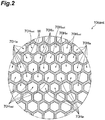
- Figure 2 is a cross-section of the central partition walls 10 cent of the honeycomb structured body 10.
- the central partition walls 10 cent form many inlet flow passages 70H in and many outlet flow passages 70H out sectional areas of which are individually substantially constant along the axial direction.
- the inlet flow passages 70H in and the outlet flow passages 70H out are regularly arranged in such a way that in the central partition walls 10 cent , one inlet flow passage 70H in is adjacent to three other inlet flow passages 70H in and adjacent to three outlet flow passages 70H out .
- One outlet flow passage 70H out is adjacent to six inlet flow passages 70H in and not adjacent to the other outlet flow passages 70H out .
- Each flow passage is adjacent to totally six flow passages respectively via the partition walls.
- the sectional shapes of the inlet flow passages 70H in and the outlet flow passages 70H out are substantially hexagonal.
- the thickness of a portion W that separates two flow passages in the central partition wall 10 cent can be set, for example, to be 0.10 to 0.35 mm.
- the density of the flow passages can be set, for example, to be 150 to 400 cpsi.
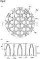
- inlet-side inclined partition walls 10 in are inclined relative to the axis of the inlet flow passages 70H in and the outlet flow passages 70H out in such a way as to gradually expand the sectional areas of the inlet flow passages 70H in and to gradually shrink and close the sectional areas of the outlet flow passages 70H out as compared with the central partition walls 10 cent , from the central partition walls 10 cent toward the inlet end face 10E in .
- the inlet-side inclined partition walls 10 in gradually expand the sectional areas of the inlet flow passages 70H in which are substantially hexagonal in the central partition walls 10 cent and make the sectional shapes triangular on the inlet end face 10E in , and make the sectional areas of the outlet flow passages 70H out 0 before reaching the inlet end face 10E in , from the central partition walls 10 cent toward the inlet end face 10E in .
- the vertices of each triangle forming the expanded inlet flow passage 70H in reach the centers of the outlet flow passages 70H out , and in this way, the outlet flow passages 70H out are closed.
- the thickness of a plate-like portion separating two flow passages can be set, for example, to be 0.10 to 0.35 mm. This thickness can be a thickness within ⁇ 10% relative to the thickness of the partition wall in the central partition walls 10 cent .
- outlet-side inclined partition walls (other-end-side inclined partition walls) 10 out are shown.
- the outlet-side inclined partition walls 10 out are inclined relative to the axis of the inlet flow passages 70H in and the outlet flow passages 70H out in such a way as to gradually expand the sectional areas of the outlet flow passages 70H out and to gradually shrink and close the sectional areas of the inlet flow passages 70H in as compared with the central partition walls 10 cent , from the central partition walls 10 cent toward the outlet end face 10E out .
- the outlet-side inclined partition walls 10 out gradually expand the sectional areas of the outlet flow passages 70H out which are substantially hexagonal in the central partition walls 10 cent into hexagons, side portions of each of the outlet flow passages 70H out becoming the corners of the hexagon, and make the sectional areas of the outlet flow passages 70H out 0 before reaching the outlet end face 10E out , from the central partition walls 10 cent to the outlet end face 10E out .
- the vertices of each hexagon of the expanded outlet flow passage 70H out reach the vicinities of the centers of the inlet flow passages 70H in , and in this way, the inlet flow passages 70H in are closed.
- the thickness of a plate-like portion separating two flow passages can be set, for example, to be 0.10 to 0.8 mm.
- This thickness can set to be a thickness equivalent to (for example, not less than 0.9 times) the thickness of the partition wall in the central partition walls 10 cent or not less than the thickness of the partition wall, and its upper limit can be made large up to the length of opposite sides (see Figure 2 ) out of the contour lines of substantial hexagons of two adjacent inlet flow passages 70H in in the central partition walls 10 cent .
- An aperture ratio on the inlet end face 10E in can be made larger than an aperture ratio on the outlet end face 10E out .
- an axial-directional length H out of the outlet-side inclined partition wall 10 out is 4 mm or more.
- the upper limit of H out does not specially exist but it can be set, for example, to be 20 mm or less.
- An axial-directional length H in of the inlet-side inclined partition wall 10 in is not specially limited but it can be set, for example, to be 4 mm or more, and also, to be 20 mm or less.
- the axial-directional lengths H in and H out of the inclined partition walls can also have dispersions on the individual flow passages, and in such a case, the arithmetic mean of those only has to satisfy the aforementioned requirement.
- the material of the honeycomb structured body 10 is porous ceramics, which have pores that gas can pass through, and on the other hand, that can capture particles such as soot.
- the ceramics include aluminum titanate, silicon carbide and cordierite.
- Aluminum titanate can contain magnesium, silicon and the like.
- the porosity of the partition wall of the honeycomb structured body 10 can be set, for example, to be 40 to 70%.
- a catalyst may be supported on the surface of the honeycomb structured body 10.
- the catalyst include particles of at least one metal element selected from the group consisting of Pt, Pd, Rh, silver, vanadium, chromium, manganese, iron, cobalt, nickel and copper, or a zeolite catalyst.
- the particle diameter of the catalyst can be set, for example, to be 1 nm to 10 ⁇ m.
- the catalyst may be directly supported on the surface of the honeycomb structured body 10, it can also be held on a support held on the honeycomb structured body.
- the support sometimes functions as a co-catalyst.
- the support examples include particles of oxides such as alumina, silica, magnesia, titania, zirconia, ceria, La 2 O 3 , BaO and zeolite, or composite oxides containing one or more of these.
- the particle diameter of the support can be set, for example, to be 0.1 to 100 ⁇ m.
- the honeycomb filter 100 as above can have a lower initial pressure loss. Specifically, the effect of reducing a pressure loss by an end surface of the inlet flow passage 70H in being set to be an inclined surface by the outlet-side inclined partition wall 10 out is high.
- the axial-directional length H out of the outlet-side inclined partition wall 10 out is 4 mm or more, the end surface is sufficiently inclined relative to the axis as compared with the case where the end surface of the inlet flow passage 70H in is orthogonal to the axis of the flow passage as in conventional plug closing, and hence, sufficient reduction of the pressure loss is possible. Accordingly, an initial pressure loss of the honeycomb filter 100 can be suppressed.
- a ceramic raw material undergoes extrusion molding by an extrusion molding machine to produce a honeycomb compact having the same sectional shape as that of the central partition walls 10 cent .
- This honeycomb compact has unclosed inlet flow passages 70H in and unclosed outlet flow passages 70H out in the state of these being penetrated.
- the composition of the ceramic raw material only has to be one with which porous ceramics are given after firing it.
- it can contain the ceramic raw material, an organic binder, a pore-forming agent, a solvent, and an additive which is added as needed.
- the ceramic raw material is powder containing elements composing the ceramics.
- the binder can be an organic binder, and examples thereof include: celluloses such as methylcelluloses, carboxymethylcelluloses, hydroxyalkylmethylcelluloses and sodium carboxymethylcelluloses; alcohols such as poly(vinyl alcohol); and lignin sulfonate salts.
- the additive include, for example, lubricants, plasticizers and dispersants.
- the inlet-side inclined partition walls 10 in are formed on the inlet end face 10E in of an obtained unfired honeycomb compact 100'.
- a closing jig 400 having many triangular pyramidal projections 410a is prepared.
- the closing jig 400 is moved in such a way that each projection 410a comes into the inlet flow passage 70H in .
- the partition walls of the inlet flow passage 70H in are deformed and the sectional area of the flow passage is expanded, and meanwhile, the sectional areas of the outlet flow passages 70H out are shrunk.
- the outlet-side inclined partition walls 10 out are formed on the outlet end face 10E out .
- Projections of a closing jig inserted into the outlet flow passages 70H out can be set to be hexagonal pyramidal. After that, after drying as needed, the honeycomb compact 100' both of whose end faces have been sealed is fired to obtain the honeycomb structured body.
- the catalyst can be supported on the honeycomb structured body 10 as needed by a known method.
- each flow passage can be arranged in such a way that one inlet flow passage 70H in is adjacent to four other inlet flow passages 70H in and adjacent to two outlet flow passages 70H out and that one outlet flow passage 70H out is adjacent to six inlet flow passages 70H in and not adjacent to the other outlet flow passages 70H out .
- that "two flow passages are adjacent to each other" can mean that two flow passages are separated from each other via one partition wall in the thickness direction of the partition wall.
- any shapes of the inclined partition walls are sufficient as long as the sectional area of each inlet flow passage is shrunk and the sectional area of each outlet flow passage is expanded from the central partition walls toward the other end face, and detailed shapes can be properly modified in accordance with the sectional shape of each flow passage and the arrangement of the flow passages.
- sectional shape of the flow passage is not specially limited to that in the aforementioned embodiment but a polygon such as a tetragon or an octagon, a circle, or the like is possible.
- honeycomb structured body 10 of the aforementioned embodiment has a structure having inlet inclined partition walls on the inlet side
- implementation thereof is possible even with a structure in which the inlet flow passages are closed with plugs at the inlet end and which does not have the inlet-side inclined partition walls.
- the external shape of the filter does not have to be a cylindrical body but may be, for example, a quadrangular prism.
- a cordierite-made porous honeycomb structured body onto which a catalyst was not adhered and that had a structure as shown in Figure 1 to Figure 4 for the aforementioned embodiment was prepared.
- the outer diameter was 118.4 mm
- the length was 113.4 mm
- the cell density was 360 cpsi
- the wall thickness was 10 mil (0.25 mm)
- the aperture ratio at the inlet end was 42%
- the aperture ratio at the outlet end was 27%
- the porosity of the partition walls was 58%
- the average pore diameter was 18 ⁇ m.
- the axial-directional length H in of the inlet-side inclined partition walls and the axial-directional length H out of the outlet-side inclined partition walls were set to be 2 to 3 mm (2.5 mm on average) and 2 to 3 mm (2.5 mm on average), respectively.
- a pressure loss when air at 600 Nm 3 /h was fed at room temperature was 5.80 kPa.
- the cell density was changed from 360 cpsi to 250 cpsi. Due to the change of the cell density, the inlet-side aperture ratio became 43% from 42%, and the outlet-side aperture ratio became 30% from 27%. This was set to be the same as Reference Example 1 except the above.
- the pressure loss was 4.46 kPa.
- Table 1 presents the results.
- Table 1 Cell Density [cpsi] Wall Thickness [mil] Inlet-Side Aperture Ratio [%] Outlet-Side Aperture Ratio [%] Hin [mm] Hout [mm] Pressure Loss at 600 Nm 3 /h [kPa]
- Reference Example 1 360 10 42 27 2.5 mm on Average 2.5 mm on Average 5.80
- Reference Example 2 360 10 42 27 0 2.5 mm on Average 6.00
- Reference Example 3 360 10 42 27 2.5 mm on Average 0 6.86 Reference Example 4 360 10 42 27 0 0 7.67 Comparative Example 1 250 10 43 30 2.5 mm on Average 2.5 mm on Average 4.46
- Example 1 250 10 43 30 2.5 mm on Average 4.5 mm on Average 4.18
Landscapes
- Chemical & Material Sciences (AREA)
- Physics & Mathematics (AREA)
- Geometry (AREA)
- Chemical Kinetics & Catalysis (AREA)
- Engineering & Computer Science (AREA)
- Geology (AREA)
- Life Sciences & Earth Sciences (AREA)
- Ceramic Engineering (AREA)
- Materials Engineering (AREA)
- Organic Chemistry (AREA)
- Inorganic Chemistry (AREA)
- Filtering Materials (AREA)
- Filtering Of Dispersed Particles In Gases (AREA)
- Exhaust Gas Treatment By Means Of Catalyst (AREA)
- Catalysts (AREA)
Abstract
Description
- The present invention relates to a honeycomb structured body.
- There is conventionally known a honeycomb structured body in which flow passages as closing targets are closed not by closing with plugs but by deforming partition walls, that is, by inclining the partition walls at an end part in such a way as to expand the sectional areas of flow passages adjacent to the flow passages as the closing targets.
-
- Patent Literature 1: Japanese Unexamined Patent Publication No.
2003-166410 - Patent Literature 2: Japanese Unexamined Patent Publication No.
2003-49631 - Although it is expected that such a honeycomb structured body achieves a smaller pressure loss as compared with a honeycomb structured body closed with plugs, the effect of reducing a pressure loss is not sufficient.
- The present invention is devised in view of the aforementioned problem, and an object thereof is to provide a honeycomb structured body high in effect of reducing a pressure loss.
- A honeycomb structured body according to the present invention is a column-shaped porous honeycomb structured body which forms a plurality of first flow passages that are opened on one end face and closed on the other end face and a plurality of second flow passages that are closed on the one end face and opened on the other end face. This honeycomb structured body comprises: central partition walls where sectional areas of each first flow passage and each second flow passage are individually constant in an axial direction; and other-end-side inclined partition walls where the sectional area of each first flow passage is shrunk and the sectional area of each second flow passage is expanded from the central partition walls toward the other end face. Further, an axial-directional length of the other-end-side inclined partition wall is 4 mm or more.
- According to the present invention, since the axial-directional length of the other-end-side inclined partition wall is secured to be 4 mm or more, an effect of reducing a pressure loss by means of inclined surfaces of the inclined partition walls can be sufficiently secured.
- Here, since even if the axial-directional length of the other-end-face-side inclined partition wall is made too large, their production becomes difficult, and in addition, the effect of reducing a pressure loss is not improved very much, it is preferable that the axial-directional length of the other-end-side inclined partition wall be 20 mm or less.
- Moreover, the honeycomb structured body further comprises one-end-side inclined partition walls where the sectional area of each first flow passage is expanded and the sectional area of each second flow passage is shrunk from the central partition walls toward the one end face.
- Moreover, the one end face can be an inlet side of gas and the other end face can be an outlet side of the gas.
- According to the present invention, a honeycomb structured body high in effect of reducing a pressure loss is provided.
-
- [
Figure 1] Figure 1 is a perspective view of ahoneycomb filter 100 according to a first embodiment. - [
Figure 2] Figure 2 is a cross-sectional view ofcentral partition walls 10cent of a honeycomb structuredbody 10 taken along II-II inFigure 1 . - [
Figure 3] Figure 3(a) is an expanded view of an end face of an inlet (one-end-side) end face 10Ein inFigure 1 , andFigure 3(b) is a cross-sectional view taken along b-b inFigure 3(a) . - [
Figure 4] Figure 4(a) is an expanded view of an end face of an outlet (other-end-side) end face 10Eout inFigure 1 , andFigure 4(b) is a cross-sectional view taken along b-b inFigure 4(a) - [
Figure 5] Figure 5 is a schematic diagram showing a method for producing a honeycomb filter according to the first embodiment. - A first embodiment of the present invention is described with reference to the drawings.
- A
honeycomb filter 100 according to the embodiment includes a column-shaped porous honeycomb structuredbody 10 as shown inFigure 1 . The honeycomb structuredbody 10 has an inlet end face (one end face) 10Ein and an outlet end face (the other end face) 10Eout. The honeycomb structuredbody 10 forms a plurality of inlet flow passages (plurality of first flow passages) 70Hin that are opened on the inlet end face 10Ein and closed on the outlet end face 10Eout, and a plurality of outlet flow passages (plurality of second flow passages) 70Hout that are closed on the inlet end face 10Ein and opened on the outlet end face 10Eout, and these flow passages extend in the axial direction of the honeycomb structuredbody 10. Moreover, the honeycomb structuredbody 10 has inlet-side inclined partition walls (one-end-side inclined partition walls) 10in having the inlet end face 10Ein, outlet-side inclined partition walls (other-end-side inclined partition walls) 10out having the outlet end face 10Eout, andcentral partition walls 10cent between these. - The outer diameter of the honeycomb structured
body 10 can be set, for example, to be 50 to 250 mm. The axial-directional length of the honeycomb structuredbody 10 can be set, for example, to be 50 to 300 mm. -
Figure 2 is a cross-section of thecentral partition walls 10cent of the honeycomb structuredbody 10. Thecentral partition walls 10cent form many inlet flow passages 70Hin and many outlet flow passages 70Hout sectional areas of which are individually substantially constant along the axial direction. In the embodiment, the inlet flow passages 70Hin and the outlet flow passages 70Hout are regularly arranged in such a way that in thecentral partition walls 10cent, one inlet flow passage 70Hin is adjacent to three other inlet flow passages 70Hin and adjacent to three outlet flow passages 70Hout. One outlet flow passage 70Hout is adjacent to six inlet flow passages 70Hin and not adjacent to the other outlet flow passages 70Hout. Each flow passage is adjacent to totally six flow passages respectively via the partition walls. In thecentral partition walls 10cent, the sectional shapes of the inlet flow passages 70Hin and the outlet flow passages 70Hout are substantially hexagonal. The thickness of a portion W that separates two flow passages in thecentral partition wall 10cent can be set, for example, to be 0.10 to 0.35 mm. The density of the flow passages can be set, for example, to be 150 to 400 cpsi. - Next, referring to
Figure 3(a) and Figure 3(b) , a structure of the inlet-side inclined partition walls (one-end-side inclined partition walls) 10in is shown. The inlet-sideinclined partition walls 10in are inclined relative to the axis of the inlet flow passages 70Hin and the outlet flow passages 70Hout in such a way as to gradually expand the sectional areas of the inlet flow passages 70Hin and to gradually shrink and close the sectional areas of the outlet flow passages 70Hout as compared with thecentral partition walls 10cent, from thecentral partition walls 10cent toward the inlet end face 10Ein. Specifically, the inlet-sideinclined partition walls 10in gradually expand the sectional areas of the inlet flow passages 70Hin which are substantially hexagonal in thecentral partition walls 10cent and make the sectional shapes triangular on the inlet end face 10Ein, and make the sectional areas of the outlet flow passages 70Hout 0 before reaching the inlet end face 10Ein, from thecentral partition walls 10cent toward the inlet end face 10Ein. On the inlet end face 10Ein, the vertices of each triangle forming the expanded inlet flow passage 70Hin reach the centers of the outlet flow passages 70Hout, and in this way, the outlet flow passages 70Hout are closed. In the inlet-sideinclined partition walls 10in, the thickness of a plate-like portion separating two flow passages can be set, for example, to be 0.10 to 0.35 mm. This thickness can be a thickness within ±10% relative to the thickness of the partition wall in thecentral partition walls 10cent. - Next, referring to
Figure 4(a) and Figure 4(b) , a structure of the outlet-side inclined partition walls (other-end-side inclined partition walls) 10out is shown. The outlet-sideinclined partition walls 10out are inclined relative to the axis of the inlet flow passages 70Hin and the outlet flow passages 70Hout in such a way as to gradually expand the sectional areas of the outlet flow passages 70Hout and to gradually shrink and close the sectional areas of the inlet flow passages 70Hin as compared with thecentral partition walls 10cent, from thecentral partition walls 10cent toward the outlet end face 10Eout. Specifically, the outlet-sideinclined partition walls 10out gradually expand the sectional areas of the outlet flow passages 70Hout which are substantially hexagonal in thecentral partition walls 10cent into hexagons, side portions of each of the outlet flow passages 70Hout becoming the corners of the hexagon, and make the sectional areas of the outlet flow passages 70Hout 0 before reaching the outlet end face 10Eout, from thecentral partition walls 10cent to the outlet end face 10Eout. On the outlet end face 10Eout, the vertices of each hexagon of the expanded outlet flow passage 70Hout reach the vicinities of the centers of the inlet flow passages 70Hin, and in this way, the inlet flow passages 70Hin are closed. In the outlet-sideinclined partition walls 10out, the thickness of a plate-like portion separating two flow passages can be set, for example, to be 0.10 to 0.8 mm. This thickness can set to be a thickness equivalent to (for example, not less than 0.9 times) the thickness of the partition wall in thecentral partition walls 10cent or not less than the thickness of the partition wall, and its upper limit can be made large up to the length of opposite sides (seeFigure 2 ) out of the contour lines of substantial hexagons of two adjacent inlet flow passages 70Hin in thecentral partition walls 10cent. - An aperture ratio on the inlet end face 10Ein can be made larger than an aperture ratio on the outlet end face 10Eout.
- In the embodiment, an axial-directional length Hout of the outlet-side
inclined partition wall 10out is 4 mm or more. The upper limit of Hout does not specially exist but it can be set, for example, to be 20 mm or less. An axial-directional length Hin of the inlet-sideinclined partition wall 10in is not specially limited but it can be set, for example, to be 4 mm or more, and also, to be 20 mm or less. - Notably, the axial-directional lengths Hin and Hout of the inclined partition walls can also have dispersions on the individual flow passages, and in such a case, the arithmetic mean of those only has to satisfy the aforementioned requirement.
- The material of the honeycomb structured
body 10 is porous ceramics, which have pores that gas can pass through, and on the other hand, that can capture particles such as soot. Examples of the ceramics include aluminum titanate, silicon carbide and cordierite. Aluminum titanate can contain magnesium, silicon and the like. The porosity of the partition wall of the honeycomb structuredbody 10 can be set, for example, to be 40 to 70%. - A catalyst may be supported on the surface of the honeycomb structured
body 10. Examples of the catalyst include particles of at least one metal element selected from the group consisting of Pt, Pd, Rh, silver, vanadium, chromium, manganese, iron, cobalt, nickel and copper, or a zeolite catalyst. The particle diameter of the catalyst can be set, for example, to be 1 nm to 10 µm. - While the catalyst may be directly supported on the surface of the honeycomb structured
body 10, it can also be held on a support held on the honeycomb structured body. The support sometimes functions as a co-catalyst. - Examples of the support include particles of oxides such as alumina, silica, magnesia, titania, zirconia, ceria, La2O3, BaO and zeolite, or composite oxides containing one or more of these. The particle diameter of the support can be set, for example, to be 0.1 to 100 µm.
- Subsequently, operation of the honeycomb filter according to the embodiment is described. As compared with a
honeycomb filter 100 in which flow passages are closed with plugs, thehoneycomb filter 100 as above can have a lower initial pressure loss. Specifically, the effect of reducing a pressure loss by an end surface of the inlet flow passage 70Hin being set to be an inclined surface by the outlet-sideinclined partition wall 10out is high. In particular, since in the embodiment, the axial-directional length Hout of the outlet-sideinclined partition wall 10out is 4 mm or more, the end surface is sufficiently inclined relative to the axis as compared with the case where the end surface of the inlet flow passage 70Hin is orthogonal to the axis of the flow passage as in conventional plug closing, and hence, sufficient reduction of the pressure loss is possible. Accordingly, an initial pressure loss of thehoneycomb filter 100 can be suppressed. - Subsequently, a method for producing such a honeycomb filter is described. First, a ceramic raw material undergoes extrusion molding by an extrusion molding machine to produce a honeycomb compact having the same sectional shape as that of the
central partition walls 10cent. This honeycomb compact has unclosed inlet flow passages 70Hin and unclosed outlet flow passages 70Hout in the state of these being penetrated. - The composition of the ceramic raw material only has to be one with which porous ceramics are given after firing it. For example, it can contain the ceramic raw material, an organic binder, a pore-forming agent, a solvent, and an additive which is added as needed.
- The ceramic raw material is powder containing elements composing the ceramics. The binder can be an organic binder, and examples thereof include: celluloses such as methylcelluloses, carboxymethylcelluloses, hydroxyalkylmethylcelluloses and sodium carboxymethylcelluloses; alcohols such as poly(vinyl alcohol); and lignin sulfonate salts. Examples of the additive include, for example, lubricants, plasticizers and dispersants.
- Subsequently, as shown in
Figure 5 , the inlet-sideinclined partition walls 10in are formed on the inlet end face 10Ein of an obtained unfired honeycomb compact 100'. Specifically, a closingjig 400 having many triangularpyramidal projections 410a is prepared. Then, the closingjig 400 is moved in such a way that eachprojection 410a comes into the inlet flow passage 70Hin. In this way, the partition walls of the inlet flow passage 70Hin are deformed and the sectional area of the flow passage is expanded, and meanwhile, the sectional areas of the outlet flow passages 70Hout are shrunk. Then, finally, as shown inFigure 3(a) and Figure 3(b) , the sectional shapes of the inlet flow passages 70Hin become triangular, and the partition walls are completely crimped in the outlet flow passages 70Hout and the outlet flow passages 70Hout are sealed. Namely, the outlet flow passages 70Hout are closed on the inlet end face 10Ein. Notably, vibration or ultrasonic waves may be given to the closingjig 400. - Next, likewise, the outlet-side
inclined partition walls 10out are formed on the outlet end face 10Eout. Projections of a closing jig inserted into the outlet flow passages 70Hout can be set to be hexagonal pyramidal. After that, after drying as needed, the honeycomb compact 100' both of whose end faces have been sealed is fired to obtain the honeycomb structured body. - Subsequently, the catalyst can be supported on the honeycomb structured
body 10 as needed by a known method. - Notably, the present invention is not limited to the aforementioned embodiment but various modifications thereof are possible. For example, arrangements of the inlet flow passages and the outlet flow passages, that is, the numbers of flow passages adjacent to each flow passage are also not limited to those in the aforementioned embodiment. For example, each flow passage can be arranged in such a way that one inlet flow passage 70Hin is adjacent to four other inlet flow passages 70Hin and adjacent to two outlet flow passages 70Hout and that one outlet flow passage 70Hout is adjacent to six inlet flow passages 70Hin and not adjacent to the other outlet flow passages 70Hout. Notably, in the present specification, that "two flow passages are adjacent to each other" can mean that two flow passages are separated from each other via one partition wall in the thickness direction of the partition wall.
- Moreover, any shapes of the inclined partition walls are sufficient as long as the sectional area of each inlet flow passage is shrunk and the sectional area of each outlet flow passage is expanded from the central partition walls toward the other end face, and detailed shapes can be properly modified in accordance with the sectional shape of each flow passage and the arrangement of the flow passages.
- Moreover, the sectional shape of the flow passage is not specially limited to that in the aforementioned embodiment but a polygon such as a tetragon or an octagon, a circle, or the like is possible.
- Moreover, while the honeycomb structured
body 10 of the aforementioned embodiment has a structure having inlet inclined partition walls on the inlet side, implementation thereof is possible even with a structure in which the inlet flow passages are closed with plugs at the inlet end and which does not have the inlet-side inclined partition walls. - Furthermore, the external shape of the filter does not have to be a cylindrical body but may be, for example, a quadrangular prism.
- A cordierite-made porous honeycomb structured body onto which a catalyst was not adhered and that had a structure as shown in
Figure 1 to Figure 4 for the aforementioned embodiment was prepared. The outer diameter was 118.4 mm, the length was 113.4 mm, the cell density was 360 cpsi, the wall thickness was 10 mil (0.25 mm), the aperture ratio at the inlet end was 42%, the aperture ratio at the outlet end was 27%, the porosity of the partition walls was 58%, and the average pore diameter was 18 µm. The axial-directional length Hin of the inlet-side inclined partition walls and the axial-directional length Hout of the outlet-side inclined partition walls were set to be 2 to 3 mm (2.5 mm on average) and 2 to 3 mm (2.5 mm on average), respectively. A pressure loss when air at 600 Nm3/h was fed at room temperature was 5.80 kPa. - This was set to be the same as Reference Example 1 except that the axial-directional length Hin of the inlet-side inclined partition walls was set to be 0, that is, the inlet side was closed with plugs. The pressure loss was 6.00 kPa.
- This was set to be the same as Reference Example 1 except that the axial-directional length Hout of the outlet-side inclined partition walls was set to be 0, that is, the outlet side was closed with plugs. The pressure loss was 6.86 kPa.
- This was set to be the same as Reference Example 1 except that the axial-directional length Hin of the inlet-side inclined partition walls was set to be 0 and the axial-directional length Hout of the outlet-side inclined partition walls, that is, both the inlet side and the outlet side were closed with plugs. The pressure loss was 7.67 kPa.
- It is found from these experiments that to provide the inclined partition walls on the outlet side is more effective for reduction of a pressure loss than to provide the inclined partition walls on the inlet side.
- The cell density was changed from 360 cpsi to 250 cpsi. Due to the change of the cell density, the inlet-side aperture ratio became 43% from 42%, and the outlet-side aperture ratio became 30% from 27%. This was set to be the same as Reference Example 1 except the above. The pressure loss was 4.46 kPa.
- This was set to be the same as Comparative Example 1 except that the axial-directional length Hout of the outlet-side inclined partition walls was set to be 4 to 5 mm (4.5 mm on average). The pressure loss was 4.18 kPa.
- Table 1 presents the results.
[Table 1] Table 1 Cell Density [cpsi] Wall Thickness [mil] Inlet-Side Aperture Ratio [%] Outlet-Side Aperture Ratio [%] Hin [mm] Hout [mm] Pressure Loss at 600 Nm3/h [kPa] Reference Example 1 360 10 42 27 2.5 mm on Average 2.5 mm on Average 5.80 Reference Example 2 360 10 42 27 0 2.5 mm on Average 6.00 Reference Example 3 360 10 42 27 2.5 mm on Average 0 6.86 Reference Example 4 360 10 42 27 0 0 7.67 Comparative Example 1 250 10 43 30 2.5 mm on Average 2.5 mm on Average 4.46 Example 1 250 10 43 30 2.5 mm on Average 4.5 mm on Average 4.18 -
- 70Hin Inlet flow passage (first flow passage)
- 70Hout Outlet flow passage (second flow passage)
- 10 Honeycomb structured body
- 10cent Central partition wall
- 10out Outlet-side inclined partition wall (other-end-side inclined partition wall)
- 10in Inlet-side inclined partition wall (one-end-side inclined partition wall)
- 10Ein Inlet end face (one end face)
- 10Eout Outlet end face (the other end face)
- 100 Honeycomb filter
- W Portion separating two flow passages
- Hin Axial-directional length of the inlet-side inclined partition wall
- (one-end-side inclined partition wall)
- Hout Axial-directional length of the outlet-side inclined partition wall (other-end-side inclined partition wall)
- 400 Closing jig
- 410a Projection
Claims (5)
- A column-shaped porous honeycomb structured body which forms a plurality of first flow passages that are opened on one end face and closed on the other end face and a plurality of second flow passages that are closed on the one end face and opened on the other end face, the honeycomb structured body comprising:central partition walls where sectional areas of each first flow passage and each second flow passage are individually constant in an axial direction; andother-end-side inclined partition walls where the sectional area of each first flow passage is shrunk and the sectional area of each second flow passage is expanded from the central partition walls toward the other end face, whereinan axial-directional length of the other-end-side inclined partition wall is 4 mm or more.
- The honeycomb structured body according to claim 1, wherein the axial-directional length of the other-end-side inclined partition wall is 20 mm or less.
- The honeycomb structured body according to claim 1 or 2, further comprising one-end-side inclined partition walls where the sectional area of each first flow passage is expanded and the sectional area of each second flow passage is shrunk from the central partition walls toward the one end face.
- The honeycomb structured body according to any one of claims 1 to 3, wherein the one end face is an inlet side of gas and the other end face is an outlet side of the gas.
- A honeycomb filter comprising:the honeycomb structured body according to any one of claims 1 to 4; anda catalyst.
Applications Claiming Priority (2)
| Application Number | Priority Date | Filing Date | Title |
|---|---|---|---|
| JP2014255508 | 2014-12-17 | ||
| PCT/JP2015/085279 WO2016098835A1 (en) | 2014-12-17 | 2015-12-16 | Honeycomb structured body |
Publications (2)
| Publication Number | Publication Date |
|---|---|
| EP3235565A1 true EP3235565A1 (en) | 2017-10-25 |
| EP3235565A4 EP3235565A4 (en) | 2018-08-01 |
Family
ID=56126719
Family Applications (1)
| Application Number | Title | Priority Date | Filing Date |
|---|---|---|---|
| EP15870037.7A Withdrawn EP3235565A4 (en) | 2014-12-17 | 2015-12-16 | Honeycomb structured body |
Country Status (4)
| Country | Link |
|---|---|
| US (1) | US20170354913A1 (en) |
| EP (1) | EP3235565A4 (en) |
| JP (1) | JPWO2016098835A1 (en) |
| WO (1) | WO2016098835A1 (en) |
Families Citing this family (7)
| Publication number | Priority date | Publication date | Assignee | Title |
|---|---|---|---|---|
| USD894361S1 (en) * | 2018-02-20 | 2020-08-25 | Ngk Insulators, Ltd. | Catalyst carrier for exhaust gas purification |
| JP7253892B2 (en) * | 2018-10-12 | 2023-04-07 | イビデン株式会社 | honeycomb structure |
| JP2020059638A (en) * | 2018-10-12 | 2020-04-16 | イビデン株式会社 | Honeycomb structure |
| JP7213054B2 (en) * | 2018-10-12 | 2023-01-26 | イビデン株式会社 | honeycomb structure |
| JP7154931B2 (en) * | 2018-10-12 | 2022-10-18 | イビデン株式会社 | honeycomb structure |
| JP2020059635A (en) * | 2018-10-12 | 2020-04-16 | イビデン株式会社 | Honeycomb structure |
| JP2020059011A (en) * | 2018-10-12 | 2020-04-16 | イビデン株式会社 | Honeycomb structure |
Family Cites Families (7)
| Publication number | Priority date | Publication date | Assignee | Title |
|---|---|---|---|---|
| DK40293D0 (en) * | 1993-04-05 | 1993-04-05 | Per Stobbe | METHOD OF PREPARING A FILTER BODY |
| JP4186530B2 (en) * | 2001-08-28 | 2008-11-26 | 株式会社デンソー | Manufacturing method of exhaust gas purification filter |
| JP3872384B2 (en) * | 2002-06-13 | 2007-01-24 | トヨタ自動車株式会社 | Exhaust gas purification filter catalyst |
| JP2004321848A (en) * | 2003-04-21 | 2004-11-18 | Ngk Insulators Ltd | Honeycomb structure and its manufacturing method |
| JP4767491B2 (en) * | 2003-12-11 | 2011-09-07 | 日本碍子株式会社 | Honeycomb structure |
| JP4946033B2 (en) * | 2005-03-01 | 2012-06-06 | 株式会社デンソー | Manufacturing method of exhaust gas purification filter |
| WO2015133435A1 (en) * | 2014-03-03 | 2015-09-11 | 住友化学株式会社 | Honeycomb filter |
-
2015
- 2015-12-16 WO PCT/JP2015/085279 patent/WO2016098835A1/en not_active Ceased
- 2015-12-16 EP EP15870037.7A patent/EP3235565A4/en not_active Withdrawn
- 2015-12-16 JP JP2016564894A patent/JPWO2016098835A1/en active Pending
- 2015-12-16 US US15/537,221 patent/US20170354913A1/en not_active Abandoned
Also Published As
| Publication number | Publication date |
|---|---|
| EP3235565A4 (en) | 2018-08-01 |
| US20170354913A1 (en) | 2017-12-14 |
| WO2016098835A1 (en) | 2016-06-23 |
| JPWO2016098835A1 (en) | 2017-10-05 |
Similar Documents
| Publication | Publication Date | Title |
|---|---|---|
| EP3235565A1 (en) | Honeycomb structured body | |
| EP2505570B1 (en) | Honeycomb structure, manufacturing method thereof, and catalyst carrying honeycomb structure | |
| JP5405538B2 (en) | Honeycomb structure | |
| CN102933279B (en) | Ceramic honeycomb structural body | |
| US9346043B2 (en) | Honeycomb structure and honeycomb catalyst | |
| US20170065919A1 (en) | Honeycomb Filter, and Method for Manufacturing Honeycomb Filter | |
| JP2004315346A (en) | Honeycomb structure | |
| JP5964205B2 (en) | Green honeycomb molded body pedestal and diesel particulate filter manufacturing method | |
| WO2013099814A1 (en) | Extrusion-molding die | |
| WO2016098834A1 (en) | Honeycomb filter and method for manufacturing honeycomb filter | |
| US11312662B2 (en) | High isostatic strength honeycomb structures and extrusion dies therefor | |
| US20180169896A1 (en) | Manufacturing method of honeycomb structure | |
| JP2013132881A (en) | Extrusion molding die | |
| JP5667663B2 (en) | Honeycomb structure | |
| WO2020075602A1 (en) | Honeycomb structure | |
| WO2015159823A1 (en) | Method for manufacturing honeycomb filter and honeycomb filter | |
| WO2020075601A1 (en) | Honeycomb structure | |
| JP2013154549A (en) | Method for sealing honeycomb structure |
Legal Events
| Date | Code | Title | Description |
|---|---|---|---|
| STAA | Information on the status of an ep patent application or granted ep patent |
Free format text: STATUS: THE INTERNATIONAL PUBLICATION HAS BEEN MADE |
|
| PUAI | Public reference made under article 153(3) epc to a published international application that has entered the european phase |
Free format text: ORIGINAL CODE: 0009012 |
|
| STAA | Information on the status of an ep patent application or granted ep patent |
Free format text: STATUS: REQUEST FOR EXAMINATION WAS MADE |
|
| 17P | Request for examination filed |
Effective date: 20170717 |
|
| AK | Designated contracting states |
Kind code of ref document: A1 Designated state(s): AL AT BE BG CH CY CZ DE DK EE ES FI FR GB GR HR HU IE IS IT LI LT LU LV MC MK MT NL NO PL PT RO RS SE SI SK SM TR |
|
| AX | Request for extension of the european patent |
Extension state: BA ME |
|
| DAV | Request for validation of the european patent (deleted) | ||
| DAX | Request for extension of the european patent (deleted) | ||
| RAP1 | Party data changed (applicant data changed or rights of an application transferred) |
Owner name: IBIDEN CO., LTD. |
|
| A4 | Supplementary search report drawn up and despatched |
Effective date: 20180704 |
|
| RIC1 | Information provided on ipc code assigned before grant |
Ipc: B01D 46/24 20060101AFI20180628BHEP Ipc: F01N 3/022 20060101ALI20180628BHEP Ipc: B01D 46/00 20060101ALI20180628BHEP Ipc: B01J 35/04 20060101ALI20180628BHEP Ipc: B01D 39/20 20060101ALI20180628BHEP |
|
| STAA | Information on the status of an ep patent application or granted ep patent |
Free format text: STATUS: EXAMINATION IS IN PROGRESS |
|
| 17Q | First examination report despatched |
Effective date: 20220228 |
|
| STAA | Information on the status of an ep patent application or granted ep patent |
Free format text: STATUS: THE APPLICATION HAS BEEN WITHDRAWN |
|
| 18W | Application withdrawn |
Effective date: 20220621 |