EP3235532A1 - Injection-needle cover - Google Patents
Injection-needle cover Download PDFInfo
- Publication number
- EP3235532A1 EP3235532A1 EP15870063.3A EP15870063A EP3235532A1 EP 3235532 A1 EP3235532 A1 EP 3235532A1 EP 15870063 A EP15870063 A EP 15870063A EP 3235532 A1 EP3235532 A1 EP 3235532A1
- Authority
- EP
- European Patent Office
- Prior art keywords
- base
- injection needle
- injection
- needle
- axial space
- Prior art date
- Legal status (The legal status is an assumption and is not a legal conclusion. Google has not performed a legal analysis and makes no representation as to the accuracy of the status listed.)
- Granted
Links
Images





Classifications
-
- A—HUMAN NECESSITIES
- A61—MEDICAL OR VETERINARY SCIENCE; HYGIENE
- A61M—DEVICES FOR INTRODUCING MEDIA INTO, OR ONTO, THE BODY; DEVICES FOR TRANSDUCING BODY MEDIA OR FOR TAKING MEDIA FROM THE BODY; DEVICES FOR PRODUCING OR ENDING SLEEP OR STUPOR
- A61M5/00—Devices for bringing media into the body in a subcutaneous, intra-vascular or intramuscular way; Accessories therefor, e.g. filling or cleaning devices, arm-rests
- A61M5/178—Syringes
- A61M5/31—Details
- A61M5/32—Needles; Details of needles pertaining to their connection with syringe or hub; Accessories for bringing the needle into, or holding the needle on, the body; Devices for protection of needles
- A61M5/3202—Devices for protection of the needle before use, e.g. caps
- A61M5/3204—Needle cap remover, i.e. devices to dislodge protection cover from needle or needle hub, e.g. deshielding devices
-
- A—HUMAN NECESSITIES
- A61—MEDICAL OR VETERINARY SCIENCE; HYGIENE
- A61M—DEVICES FOR INTRODUCING MEDIA INTO, OR ONTO, THE BODY; DEVICES FOR TRANSDUCING BODY MEDIA OR FOR TAKING MEDIA FROM THE BODY; DEVICES FOR PRODUCING OR ENDING SLEEP OR STUPOR
- A61M5/00—Devices for bringing media into the body in a subcutaneous, intra-vascular or intramuscular way; Accessories therefor, e.g. filling or cleaning devices, arm-rests
- A61M5/178—Syringes
- A61M5/31—Details
- A61M5/32—Needles; Details of needles pertaining to their connection with syringe or hub; Accessories for bringing the needle into, or holding the needle on, the body; Devices for protection of needles
-
- A—HUMAN NECESSITIES
- A61—MEDICAL OR VETERINARY SCIENCE; HYGIENE
- A61M—DEVICES FOR INTRODUCING MEDIA INTO, OR ONTO, THE BODY; DEVICES FOR TRANSDUCING BODY MEDIA OR FOR TAKING MEDIA FROM THE BODY; DEVICES FOR PRODUCING OR ENDING SLEEP OR STUPOR
- A61M5/00—Devices for bringing media into the body in a subcutaneous, intra-vascular or intramuscular way; Accessories therefor, e.g. filling or cleaning devices, arm-rests
- A61M5/178—Syringes
- A61M5/31—Details
- A61M5/32—Needles; Details of needles pertaining to their connection with syringe or hub; Accessories for bringing the needle into, or holding the needle on, the body; Devices for protection of needles
- A61M5/3205—Apparatus for removing or disposing of used needles or syringes, e.g. containers; Means for protection against accidental injuries from used needles
- A61M5/321—Means for protection against accidental injuries by used needles
- A61M5/3216—Caps placed transversally onto the needle, e.g. pivotally attached to the needle base
-
- A—HUMAN NECESSITIES
- A61—MEDICAL OR VETERINARY SCIENCE; HYGIENE
- A61M—DEVICES FOR INTRODUCING MEDIA INTO, OR ONTO, THE BODY; DEVICES FOR TRANSDUCING BODY MEDIA OR FOR TAKING MEDIA FROM THE BODY; DEVICES FOR PRODUCING OR ENDING SLEEP OR STUPOR
- A61M5/00—Devices for bringing media into the body in a subcutaneous, intra-vascular or intramuscular way; Accessories therefor, e.g. filling or cleaning devices, arm-rests
- A61M5/178—Syringes
- A61M5/31—Details
- A61M5/32—Needles; Details of needles pertaining to their connection with syringe or hub; Accessories for bringing the needle into, or holding the needle on, the body; Devices for protection of needles
- A61M5/3205—Apparatus for removing or disposing of used needles or syringes, e.g. containers; Means for protection against accidental injuries from used needles
- A61M5/321—Means for protection against accidental injuries by used needles
- A61M5/3243—Means for protection against accidental injuries by used needles being axially-extensible, e.g. protective sleeves coaxially slidable on the syringe barrel
- A61M5/3245—Constructional features thereof, e.g. to improve manipulation or functioning
-
- A—HUMAN NECESSITIES
- A61—MEDICAL OR VETERINARY SCIENCE; HYGIENE
- A61M—DEVICES FOR INTRODUCING MEDIA INTO, OR ONTO, THE BODY; DEVICES FOR TRANSDUCING BODY MEDIA OR FOR TAKING MEDIA FROM THE BODY; DEVICES FOR PRODUCING OR ENDING SLEEP OR STUPOR
- A61M5/00—Devices for bringing media into the body in a subcutaneous, intra-vascular or intramuscular way; Accessories therefor, e.g. filling or cleaning devices, arm-rests
- A61M5/178—Syringes
- A61M5/31—Details
- A61M5/32—Needles; Details of needles pertaining to their connection with syringe or hub; Accessories for bringing the needle into, or holding the needle on, the body; Devices for protection of needles
- A61M5/3205—Apparatus for removing or disposing of used needles or syringes, e.g. containers; Means for protection against accidental injuries from used needles
- A61M5/321—Means for protection against accidental injuries by used needles
- A61M5/3243—Means for protection against accidental injuries by used needles being axially-extensible, e.g. protective sleeves coaxially slidable on the syringe barrel
- A61M5/3275—Means for protection against accidental injuries by used needles being axially-extensible, e.g. protective sleeves coaxially slidable on the syringe barrel being connected to the needle hub or syringe by radially deflectable members, e.g. longitudinal slats, cords or bands
Definitions
- the present invention relates to an injection-needle cover.
- Patent Document 1 discloses a safe injection-needle cover which is extendable with respect to an injection needle.
- the injection-needle cover is formed by a plurality of rigid segments serially connected by a plurality of intersegment hinges.
- the rigid segments are disposed around the injection needle, folded upon each other during a medical procedure, and extended at the end of the medical procedure.
- the extended injection-needle cover protectively sheathes the injection needle.
- Patent Document 1 Japanese Translation of PCT Publication No. 2001-515767
- the injection-needle cover disclosed in Patent Document 1 fails to be extended smoothly depending on size of the needle. If the injection-needle cover cannot be extended smoothly, a health practitioner is forced to handle this trouble. If it takes time to handle the trouble, provision of care for a patient may be delayed. The delay in the provision of the care for the patient may be seriously detrimental to the patient in some cases.
- Patent Document 1 If the injection-needle cover disclosed in Patent Document 1 cannot be extended smoothly and the health practitioner tries to extend the injection-needle cover, it may cause an accident in some cases. As an example of the accident, the health practitioner may accidentally stick himself/herself with the injection needle. Such an accident may cause infection of the health practitioner in some cases.
- the present invention has been made to solve the problem. It is an object of the invention to provide an injection-needle cover which can be extended easily and smoothly.
- the invention is as follows.
- An injection-needle cover includes:
- the easy sliding portion has an injection needle contact zone extending along a direction of movement of the easy sliding portion in opening of the connecting hinge.
- the injection needle contact zone is provided with a curved face extending from one end to the other end of the injection needle contact zone in the direction of the movement of the easy sliding portion in the opening of the connecting hinge.
- the connected portion fitting space forming portion has a moment receiving portion 44 for receiving moment about the base axis as a turning center.
- the connecting portion has a bottom plate portion which is disposed in the base-side axial space to be adjacent to a boundary between the base-side axial space and the intra-cylinder space and opposite ends of which are connected to the base-side wall portions and a structural body portion protruding from an end portion of the bottom plate portion facing the intra-cylinder space toward the base-side axial space and a curved face is provided to a portion of the bottom plate portion extending from the opposite face from a face facing the base-side axial space to the end portion.
- the connecting portion has a flexible body portion which bends more in a direction from the tip-end-side axial space toward the base-side axial space than in a direction orthogonal to the direction from the tip-end-side axial space toward the base-side axial space when the force receiving portion receives the force from the injection needle.
- the flexible body portion has a plate-shaped portion disposed to be orthogonal to a bending direction which is the direction from the tip-end-side axial space toward the base-side axial space.
- the plate-shaped portion faces one of the paired base-side wall portions with a clearance left therebetween and the force receiving portion faces the one of the paired base-side wall portions, which the plate-shaped portion faces with the clearance left therebetween, with a clearance left therebetween.
- the injection needle enclosure portion further has a hook portion which is protruding into the base-side axial space and which hooks the injection needle when the injection needle becomes fitted in the base-side axial space and the tip-end-side axial space
- the hook portion has a columnar portion disposed along the paired base-side wall portions in the base-side axial space, a detachment preventing portion protruding from the columnar portion toward one of the paired base-side wall portions, and an inclined face disposed from a tip end portion of the columnar portion to a tip end portion of the detachment preventing portion and inclined with respect to a direction along the paired base-side wall portions
- the plate-shaped portion is connected to the base-side wall portion, toward which the detachment preventing portion is protruding, and faces the different base-side wall portion from the base-side wall portion, toward which the detachment preventing portion is
- the flexible body portion has a less deformable portion extending in a direction crossing the base-side wall portions and a more deformable portion extending along the less deformable portion and more deformable than the less deformable portion.
- the more deformable portion is provided with a slit extending along the less deformable portion.
- an injection-needle cover which can be extended easily and smoothly.
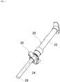
- Fig. 1 is a view showing an attached state of an injection-needle cover 30 according to the embodiment to a syringe 20.
- the injection-needle cover 30 according to the embodiment is attached to the known syringe 20.
- an injection needle 24 is covered with a cylindrical cover 26.
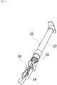
- the injection-needle cover 30 according to the embodiment encloses the injection needle 24 of the syringe 20 after the use of the syringe 20.
- Fig. 2 is a view showing a state of the injection-needle cover 30 according to the embodiment enclosing the injection needle 24.
- the cylindrical cover 26 is removed to use the syringe 20.
- a known cylinder to which the known injection needle 24 is attached is referred to as a cylinder 22.
- the injection needle 24 and the cylinder 22 to which the injection needle 24 is attached are collectively referred to as the syringe 20.
- Figs. 3(A) to 3(C) are external views of the injection-needle cover 30 according to the embodiment of the invention.
- Fig. 3(A) is a plan view of the injection-needle cover 30 according to the embodiment.
- Fig. 3(B) is a front view of the injection-needle cover 30 according to the embodiment.
- Fig. 3(C) is a bottom view of the injection-needle cover 30 according to the embodiment.
- the injection-needle cover 30 according to the embodiment will be described based on Figs. 3(A) to 3(C) .
- the injection-needle cover 30 according to the embodiment is made of synthetic resin.
- the injection-needle cover 30 includes a base portion 32, paired base hinges 34, a connected portion fitting space forming portion 36, paired connecting hinges 38, and an injection needle enclosure portion 40. In the embodiment, these parts are integrated with each other.
- the base portion 32 is in an annular shape from opposite ends of which ribs 48 are protruding.
- a smooth side face of the base portion 32 facing an injection needle protruding face 28 of the cylinder 22 and the injection needle protruding face 28 are integrated with each other by welding.
- the welding is achieved by rotating the former while pushing the former against the latter.
- the base portion 32 is fixed to the injection needle protruding face 28.
- the injection needle protruding face 28 is a smooth face of the cylinder 22 from which the injection needle 24 is protruding.
- the base portion 32 is fixed so as to enclose the injection needle 24.
- the base portion 32 includes retaining portions 42 as well. Fixing lugs 90 (described later) get caught on the retaining portions 42.
- the base hinges 34 are hinges provided to the base portion 32.
- the base hinges 34 are continuous with the ribs 48 at opposite ends of the base portion 32.
- the connected portion fitting space forming portion 36 is connected to the base portion 32 by the base hinges 34. In this way, the connected portion fitting space forming portion 36 turns about a base axis 52.
- the base axis 52 passes through the base hinges 34 and is orthogonal to a central axis 50 of the injection-needle cover 30 (the central axis 50 passes through a center of the base portion 32).
- the connected portion fitting space forming portion 36 forms a space. In the space, a portion of the injection needle 24 connected to the cylinder 22 is to become fitted (in the embodiment, not only a portion formed by a metal tube but also the connected portion is a part of the injection needle 24).
- the connected portion fitting space forming portion 36 includes paired arm portions 46 and a moment receiving portion 44.
- the arm portions 46 connect the base hinges 34 and the moment receiving portion 44.
- the paired arm portions 46 are respectively connected to the different base hinges 34.
- the moment receiving portion 44 receives moment about the base axis 52 as a turning
- the connecting hinges 38 are hinges provided to the connected portion fitting space forming portion 36 with the moment receiving portion 44 interposed therebetween.
- the injection needle enclosure portion 40 is connected to the connected portion fitting space forming portion 36 by the paired connecting hinges 38.
- the injection needle enclosure portion 40 turns about a connection axis 54.
- the connection axis 54 passes through the connecting hinges 38 and is parallel to the base axis 52.
- Fig. 4 is a perspective view of an injection needle enclosure portion 40 according to the embodiment of the invention.
- the injection needle enclosure portion 40 according to the embodiment will be described based on Fig. 4 .
- the injection needle enclosure portion 40 according to the embodiment includes paired base-side wall portions 60, a cylinder portion 62, paired tip-end-side wall portions 64, an injection needle contact portion 66, a hook portion 68, and a needle tip end fixing portion 70.
- the paired base-side wall portions 60 are disposed to face each other.
- a space between the paired base-side wall portions 60 is a base-side axial space 80.
- the paired base-side wall portions 60 form the base-side axial space 80.
- a part of the injection needle 24 is to become fitted.
- Each of the base-side wall portions 60 has the fixing lug 90.
- the fixing lugs 90 pass through the space formed by the connected portion fitting space forming portion 36 and get caught on the retaining portions 42 of the base portion 32.
- the injection-needle cover 30 takes the form shown in Fig. 1 .
- the cylinder portion 62 is continuous with the paired base-side wall portions 60.
- the cylinder portion 62 forms an intra-cylinder space 82.
- the space surrounded with an inner peripheral face of the cylinder portion 62 is the intra-cylinder space 82.
- the intra-cylinder space 82 communicates with the base-side axial space 80 through a notch formed in the cylinder portion 62.
- the paired tip-end-side wall portions 64 are disposed to face each other.
- the paired tip-end-side wall portions 64 are continuous with the cylinder portion 62.
- a space between the paired tip-end-side wall portions 64 is a tip-end-side axial space 84.
- the paired tip-end-side wall portions 64 form the tip-end-side axial space 84.
- a tip end portion of the injection needle 24 is to become fitted in the tip-end-side axial space 84.
- the tip-end-side axial space 84 communicates with the intra-cylinder space 82 through a notch formed in the cylinder portion 62.
- the paired tip-end-side wall portions 64 are disposed on the opposite side of the cylinder portion 62 from the paired base-side wall portions 60.
- the paired tip-end-side wall portions 64 are disposed so that the base-side axial space 80 and the tip-end-side axial space 84 are aligned with each other.
- the injection needle contact portion 66 is disposed at a position in the base-side axial space 80 which is a boundary between the base-side axial space 80 and the intra-cylinder space 82.
- the hook portion 68 is protruding into the base-side axial space 80.
- the hook portion 68 according to the embodiment includes a columnar portion 150, a detachment preventing portion 152, and an inclined face 154.
- the columnar portion 150 is disposed in the base-side axial space 80.
- the columnar portion 150 is provided along the paired base-side wall portions 60.
- the detachment preventing portion 152 is protruding from the columnar portion 150 toward one of the paired base-side wall portions 60.
- the inclined face 154 is disposed from a tip end portion of the columnar portion 150 to a tip end portion of the detachment preventing portion 152.
- the inclined face 154 is inclined with respect to a direction along the paired base-side wall portions 60.
- the needle tip end fixing portion 70 is protruding from one of the tip-end-side wall portions 64 into the tip-end-side axial space 84.
- the hook portion 68 and the needle tip end fixing portion 70 catch the injection needle 24 when the injection needle 24 becomes fitted into the base-side axial space 80 and the tip-end-side axial space 84.
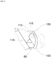
- Fig. 5 is a sectional view of an injection needle contact portion 66 according to the embodiment.
- Fig. 5 shows a section of the injection needle contact portion 66 along the central axis 50 of the injection-needle cover 30.
- the injection needle contact portion 66 according to the embodiment will be described based on Fig. 5 .
- the injection needle contact portion 66 according to the embodiment includes a force receiving portion 100 and a connecting portion 102. In the embodiment, the force receiving portion 100 and the connecting portion 102 are integrated with each other.
- the force receiving portion 100 receives a force from the injection needle 24 when the force receiving portion 100 comes in contact with the injection needle 24.
- the force receiving portion 100 includes an injection needle facing portion 110 and an easy sliding portion 112.
- the injection needle facing portion 110 faces the injection needle 24 after the injection needle 24 becomes fitted in the base-side axial space 80 and the tip-end-side axial space 84.
- the easy sliding portion 112 is disposed in an area adjacent to the injection needle.
- the area adjacent to the injection needle refers to an area of the force receiving portion 100 on a side closer to the intra-cylinder space 82 and the tip-end-side axial space 84 than the injection needle facing portion 110.
- Fig. 6 is a perspective view of the easy sliding portion 112 according to the embodiment.
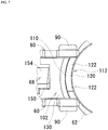
- Fig. 7 is an enlarged view of an area around a boundary between the base-side axial space 80 and the intra-cylinder space 82 in Fig. 3(A) .
- Fig. 8 is a sectional view taken along line A-A in Fig. 3(A) .
- the easy sliding portion 112 according to the embodiment will be described based on Figs. 6 to 8 .
- the easy sliding portion 112 is a portion which slides more easily along the injection needle 24 than a case where an edge 114 having an equal coefficient of static friction to the connecting portion 102 and crossing the injection needle 24 slides along the injection needle 24.
- the easy sliding portion 112 includes an injection needle contact zone 120 and paired injection needle position correcting zones 122.
- the injection needle contact zone 120 is extending along a direction of movement of the easy sliding portion 112 in opening of the connecting hinges 38. This direction is a direction from the hook portion 68 toward the injection needle facing portion 110 in Fig. 7 .
- a curved face is provided throughout the injection needle contact zone 120. The curved face extends from one end to the other end of the injection needle contact zone 120 in the direction of the movement of the easy sliding portion 112 in the opening of the connecting hinges 38.
- a radius of curvature of the curved face equals to a thickness of the injection needle contact portion 66 at a base of the force receiving portion 100 (a connection between the force receiving portion 100 and the connecting portion 102).
- the radius of curvature may be larger or smaller than the thickness of the injection needle contact portion 66.
- the paired injection needle position correcting zones 122 are disposed to sandwich the injection needle facing portion 110.
- the injection needle position correcting zones 122 are extending in a direction along the inner peripheral face of the cylinder portion 62 as well as in the direction of the movement of the easy sliding portion 112 in the opening of the connecting hinges 38. In this way, when a metal tube portion of the injection needle 24 bends, the injection needle position correcting zones 122 can correct the bend.
- curved faces are respectively provided throughout the injection needle position correcting zones 122.
- the curved faces and the curved face provided throughout the injection needle contact zone 120 are integrated with each other. In this way, it is possible to smoothly correct the bend when the metal tube portion of the injection needle 24 bends.
- the connecting portion 102 connects the paired base-side wall portions 60 and the force receiving portion 100.
- the connecting portion 102 according to the embodiment will be described based on Figs. 5 , 7 , and 8 .
- the connecting portion 102 includes a bottom plate portion 130 and a plate-shaped portion 132.
- the bottom plate portion 130 is disposed in the base-side axial space 80 to extend from a boundary between the base-side axial space 80 and the intra-cylinder space 82 to a vicinity of the connecting hinges 38. As shown in Fig. 7 , opposite ends of the bottom plate portion 130 are connected to the base-side wall portions 60. As shown in Fig. 5 , the bottom plate portion 130 is provided with a bottom curved face 140. In the embodiment, one end of the bottom curved face 140 is positioned on a face of the bottom plate portion 130 facing an outside of the injection-needle cover 30 (i.e., a face opposite from a face facing the base-side axial space 80). The other end of the bottom curved face 140 faces the intra-cylinder space 82.
- the plate-shaped portion 132 is protruding from the end portion of the bottom plate portion 130 facing the intra-cylinder space 82 (end portion provided with the bottom curved face 140) toward the base-side axial space 80.
- the plate-shaped portion 132 is disposed to be orthogonal to a bending direction.
- the bending direction refers to a direction from the tip-end-side axial space 84 toward the base-side axial space 80.
- the plate-shaped portion 132 bends more in the direction from the tip-end-side axial space 84 toward the base-side axial space 80 than in the direction orthogonal to the direction from the tip-end-side axial space 84 toward the base-side axial space 80.
- An example of "the direction orthogonal to the direction from the tip-end-side axial space 84 toward the base-side axial space 80" is a direction from one of the paired base-side wall portions 60 toward the other.
- the plate-shaped portion 132 is connected to the base-side wall portion 60 toward which the detachment preventing portion 152 of the hook portion 68 is protruding. As shown in Fig.
- the plate-shaped portion 132 faces the different base-side wall portion 60 from the base-side wall portion 60 toward which the detachment preventing portion 152 is protruding (the base-side wall portion 60 toward which the detachment preventing portion 152 is not protruding) with a clearance 160 left therebetween.
- the force receiving portion 100 is disposed similarly. Therefore, the force receiving portion 100 faces the base-side wall portion 60, which the plate-shaped portion 132 faces with the clearance 160 left therebetween, with the clearance 160 therebetween.
- the clearance 160 is 1.3 mm in width. The width of the clearance 160 is determined based on the following basis. In other words, a clearance between the paired base-side wall portions 60 is 5.8 mm.
- An outer diameter of the metal tube portion of the injection needle 24 is assumed to be between 0.65 mm and 0.50 mm inclusive.
- An assumed maximum value of the outer diameter of the metal tube portion of the injection needle 24 is 0.65 mm. If the width of the clearance 160 exceeds a half of the clearance between the paired base-side wall portions 60, the injection needle 24 may fall into the clearance 160. In order to avoid this, the width of the clearance 160 is preferably not greater than the half of the interval between the paired base-side wall portions 60. It is more preferable that the width of the clearance 160 is not greater than a value obtained by subtracting a half of the outer diameter of the injection needle 24 from the half of the interval between the paired base-side wall portions 60.
- a maximum value of the width of the clearance 160 is set to 2.575 mm. This corresponds to about 44.4% of the interval between the paired base-side wall portions 60.
- the width of the clearance 160 in the embodiment is 1.3 mm. Needless to say, the width of the clearance 160 may be different.
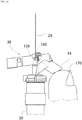
- Fig. 9 is a view showing a state of the injection-needle cover 30 according to the embodiment immediately before operation.
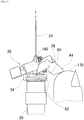
- Fig. 10 is a view showing a state of the injection-needle cover 30 according to the embodiment during operation. In this view, a part of the injection-needle cover 30 is cut away.
- Fig. 11 is a view of the injection-needle cover 30 according to the embodiment during the operation when the connecting hinges 38 insufficiently open. In this view, again, a part of the injection-needle cover 30 is cut away. The operation of the injection-needle cover 30 according to the embodiment will be described based on Figs. 9 to 11 .
- a user takes the cylindrical cover 26 off the syringe 20 held in his/her hand. If the cylindrical cover 26 is taken off, the user uses the syringe 20. A method of using the syringe 20 is known. Therefore, the method will not be described here in detail.
- the user After use of the syringe 20 is finished, the user holds the cylinder 22 of the syringe 20 in his/her hand. At this time, the user lightly touches the moment receiving portion 44 with his/her thumb 170 as shown in Fig. 9 . When the user touches the moment receiving portion 44 with his/her thumb 170, the user pushes the moment receiving portion 44 in a direction parallel to the injection needle 24 with his/her thumb 170.
- the fixing lugs 90 caught on the retaining portions 42 are detached from the retaining portions 42. If the fixing lugs 90 are detached from the retaining portions 42, the folded injection-needle cover 30 is naturally extended by resilience of the base hinges 34 and resilience of the connecting hinges 38. The base hinges 34 and the connecting hinges 38 open. As a result, as shown in Fig. 10 , the injection needle contact zone 120 of the easy sliding portion 112 comes in contact with a connected portion of the injection needle 24. At this time, the user keeps pushing the moment receiving portion 44 in the direction parallel to the injection needle 24 with his/her thumb 170. As the moment receiving portion 44 is kept pushed, the injection needle contact zone 120 moves along a base portion of the injection needle 24. A direction of movement of the injection needle contact zone 120 at this time is a direction of movement of the easy sliding portion 112 in opening of the connecting hinges 38.
- the bottom curved face 140 first comes in contact with the connected portion of the injection needle 24 as shown in Fig. 11 .
- the bottom curved face 140 moves along the connected portion of the injection needle 24.
- the direction of movement of the injection needle contact zone 120 at this time is also the direction of the movement of the easy sliding portion 112 in the opening of the connecting hinges 38.
- the injection needle contact zone 120 of the easy sliding portion 112 comes in contact with the connected portion of the injection needle 24.
- the injection needle 24 first becomes fitted in the tip-end-side axial space 84.
- the tip end portion of the injection needle 24 fitted in the tip-end-side axial space 84 gets caught on the needle tip end fixing portion 70.
- the injection needle 24 becomes fitted in the base-side axial space 80.
- the injection needle 24 fitted in the base-side axial space 80 gets caught on the hook portion 68. If a vibration caused when the hook portion 68 hooks the tip end portion of the injection needle 24 is transmitted to the user's hand, the user stops pushing the moment receiving portion 44.
- the injection-needle cover 30 protects the injection needle 24 as shown in Fig. 2 . If the injection-needle cover 30 protects the injection needle 24, the user disposes of the syringe 20 with the injection-needle cover 30 on it.
- the injection-needle cover 30 in the folded state is attached to the syringe 20 in advance.
- the injection-needle cover 30 is fixed by the base portion 32 to a face of the syringe 20 from which the injection needle 24 is protruding.
- the injection needle 24 passes through the intra-cylinder space 82.
- the injection-needle cover 30 is extended by sliding the injection needle contact portion 66 along a side face of the injection needle 24. As the injection needle contact portion 66 slides along the side face of the injection needle 24, the portion of the injection needle 24 connected to the cylinder 22 is housed in the space formed by the connected portion fitting space forming portion 36.
- the injection needle 24 passing through the intra-cylinder space 82 gradually becomes fitted in the base-side axial space 80 and the tip-end-side axial space 84.
- the injection needle 24 passes through the intra-cylinder space 82 when the injection needle 24 becomes fitted in the base-side axial space 80 and the tip-end-side axial space 84.
- the base-side axial space 80 communicates with the intra-cylinder space 82
- the intra-cylinder space 82 communicates with the tip-end-side axial space 84
- the base-side axial space 80 and the tip-end-side axial space 84 are aligned with each other, and the paired tip-end-side wall portions 64 are disposed on the opposite side of the cylinder portion 62 from the paired base-side wall portions 60.
- the base hinges 34 open.
- the connected portion fitting space forming portion 36 turns.
- the injection needle enclosure portion 40 turns as well. This is because the injection needle enclosure portion 40 is connected to the connected portion fitting space forming portion 36 by the connecting hinges 38.
- the injection needle contact portion 66 comes in contact with the side face of the injection needle 24.
- the connecting hinges 38 open insufficiently, a portion of the force receiving portion 100 which faces the injection needle 24 after the injection needle 24 becomes fitted in the base-side axial space 80 and the tip-end-side axial space 84 (i.e., injection needle facing portion 110) and an area on a side of the portion close to the tip-end-side axial space 84 come in direct contact with the side face of the injection needle 24 in many cases. If the connecting hinges 38 open insufficiently, the bottom curved face 140 rather than the injection needle facing portion 110 and the easy sliding portion 112 is likely to come in direct contact with the side face of the injection needle 24 as shown in Fig. 11 when the injection needle contact portion 66 starts to slide on the side face of the injection needle 24.
- the base hinges 34 open more than the connecting hinges 38 when the injection needle contact portion 66 starts to slide on the side face of the injection needle 24. Because the base hinges 34 open, the injection needle enclosure portion 40 turns. As a result, the injection needle contact portion 66 comes in contact with the side face of the injection needle 24. Because the force receiving portion 100 has the easy sliding portion 112 and the easy sliding portion 112 is disposed in an area adjacent to the injection needle, the force receiving portion 100 slides more easily when the injection needle contact portion 66 starts to slide on the side face of the injection needle 24 than the case where the edge 114 having the equal coefficient of static friction to a surface of the connecting portion 102 and crossing the injection needle 24 slides along the injection needle 24. Because the force receiving portion 100 slides easily, the injection-needle cover 30 is likely to be extended smoothly.
- the injection needle contact zone 120 is extending along the direction of the movement of the easy sliding portion 112 in the opening of the connecting hinges 38. Because the injection needle contact zone 120 is a zone provided to the easy sliding portion 112, the easy sliding portion 112 slides on the side face of the injection needle 24 as the connecting hinges 38 open when the injection needle contact portion 66 slides on the side face of the injection needle 24. In this way, as compared with the case in which the injection needle contact zone 120 is not extending along the direction of the movement of the easy sliding portion 112 in the opening of the connecting hinges 38, it is possible to extend the injection-needle cover 30 smoothly for a longer time.
- the injection needle contact zone 120 smoothly slides on the side face of the injection needle 24. If the injection needle contact zone 120 can slide smoothly, as compared with the case in which the injection needle contact zone 120 cannot slide smoothly, it is possible to extend the injection-needle cover 30 smoothly.
- the moment receiving portion 44 receives the moment, as compared with the case in which a portion of the injection-needle cover 30 other than the connected portion fitting space forming portion 36 receives moment (e.g., the case in which the moment is applied to the connected portion fitting space forming portion 36 via the connecting hinges 38 by pinching the tip-end-side wall portions 64 between a thumb and a finger and moving the tip-end-side wall portions 64 in the direction along the injection needle 24), direct contact of the area adjacent to the injection needle with the side face of the injection needle 24 is facilitated.
- moment e.g., the case in which the moment is applied to the connected portion fitting space forming portion 36 via the connecting hinges 38 by pinching the tip-end-side wall portions 64 between a thumb and a finger and moving the tip-end-side wall portions 64 in the direction along the injection needle 24
- the injection-needle cover 30 is more likely to be extended smoothly as compared with the case in which the connected portion fitting space forming portion 36 does not have the moment receiving portion 44.
- a portion of the bottom plate portion 130 from the opposite face from a face facing the base-side axial space 80 to an end portion facing the intra-cylinder space 82 may come in contact with the injection needle 24 earlier than the area adjacent to the injection needle in some cases. If this portion is provided with the bottom curved face 140, even if the portion comes in contact with the injection needle 24 earlier than the area adjacent to the injection needle, the portion can move smoothly after the contact.
- the injection needle contact portion 66 is more likely to start to slide on the side face of the injection needle 24 than when the plate-shaped portion 132 does not bend. If the injection needle contact portion 66 is more likely to start to slide on the side face of the injection needle 24, the injection-needle cover 30 is move likely to be extended smoothly than when the injection needle contact portion 66 is less likely to start to slide.
- the plate-shaped portion 132 By increasing a difference between a thickness and a width of the plate-shaped portion 132, it is possible to easily increase a difference between bendability of the plate-shaped portion 132 in the direction from the tip-end-side axial space 84 toward the base-side axial space 80 and bendability of the plate-shaped portion 132 in the direction orthogonal to the direction. By increasing the difference in bendability, the plate-shaped portion 132 becomes more likely to bend in the direction from the tip-end-side axial space 84 toward the base-side axial space 80. As a result, the injection-needle cover 30 becomes more likely to be extended smoothly.
- the plate-shaped portion 132 faces one of the paired base-side wall portions 60 with the clearance 160 left therebetween, a portion where the clearance 160 is provided bends easily. If the force receiving portion 100 similarly has the clearance 160, the plate-shaped portion 132 becomes more likely to bend in the direction from the tip-end-side axial space 84 toward the base-side axial space 80 than when the force receiving portion 100 does not have the clearance 160. As a result, the injection-needle cover 30 becomes more likely to be extended smoothly.
- the injection needle enclosure portion 40 further has the hook portion 68, the injection needle 24 which has become fitted in the base-side axial space 80 and the tip-end-side axial space 84 is less likely to be detached than when the injection needle enclosure portion 40 does not have the hook portion 68.
- the plate-shaped portion 132 is connected to the base-side wall portion 60 toward which the detachment preventing portion 152 is protruding, faces the different base-side wall portion 60 from the base-side wall portion 60, toward which the detachment preventing portion 152 is protruding, with the clearance 160 left therebetween, and the inclined face 154 is disposed from the tip end portion of the columnar portion 150 to the tip end portion of the detachment preventing portion 152, the injection needle 24 is less likely to become fitted in the clearance 160 than when such a hook portion 68 does not exist. If the injection needle 24 is less likely to become fitted in the clearance 160, the injection needle 24 is less likely to be covered with the injection-needle cover 30.
- the injection needle 24 which has become fitted in the base-side axial space 80 and the tip-end-side axial space 84 is less likely to be detached than when the injection needle enclosure portion 40 does not have the needle tip end fixing portion 70.
- the injection-needle cover 30 described by using Figs. 1 to 11 (hereafter referred to as "the injection-needle cover according to the invention") and a comparative injection-needle cover described below were compared with each other in terms of operation.
- the comparative injection-needle cover has the same structure as the injection-needle cover according to the invention except the following points. The points are that the comparative injection-needle cover has an edge 114 instead of the easy sliding portion 112 of the injection-needle cover according to the invention and that the comparative injection-needle cover has a bottom edge 180 instead of the bottom curved face 140.
- Fig. 12 is a sectional view of an injection needle contact portion 190 of the comparative injection-needle cover.
- An examiner prepared 1100 injection-needle covers according to the invention respectively attached to syringes as first-type samples.
- the examiner prepared 1100 injection-needle covers according to the invention respectively attached to other syringes with thick injection needles.
- the examiner prepared 1100 comparative injection-needle covers respectively attached to the same kind of syringes as the syringes with the thick injection needles.
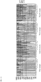
- 22 examinees evaluated smoothness of operation of each of the samples.
- Each of the examinees used 50 samples of each type.
- a percentage of A ratings for the first-type samples was 84.5%.
- a percentage of B ratings for the first-type samples was 15.5%.
- a percentage of C ratings for the first-type samples was 0.0%.
- a percentage of A ratings for the second-type samples was 57.4%.
- a percentage of B ratings for the second-type samples was 42.0%.
- a percentage of C ratings for the second-type samples was 0.6%.
- a percentage of A ratings for the third-type samples was 83.6%.
- a percentage of B ratings for the third-type sample was 16.4%.
- a percentage of C ratings for the third-type samples was 0%.
- a percentage of A ratings for the fourth-type samples was 60.4%.
- a percentage of B ratings for the fourth-type samples was 39.6%.
- a percentage of C ratings for the fourth-type samples was 0%.
- the percentage of A ratings for the first-type samples is about 30% higher than the percentage of A ratings for the second-type samples.
- the percentage of A ratings for the third-type samples is about 20% higher than the percentage of A ratings for the fourth-type samples.
- the connecting portion 102 may have a portion which is a kind of flexible body portion similarly to the plate-shaped portion but is not in a plate shape in place of the plate-shaped portion. Similarly to the plate-shaped portion, the flexible body portion bends more in a direction from a tip-end-side axial space 84 toward a base-side axial space 80 than in a direction orthogonal to the direction from the tip-end-side axial space 84 toward the base-side axial space 80 when a force receiving portion 100 receives a force from an injection needle 24.
- an injection needle contact portion 66 becomes more likely to start to slide on a side face of the injection needle 24 than when the flexible body portion does not bend. If the injection needle contact portion 66 is more likely to start to slide on the side face of the injection needle 24, an injection-needle cover 30 is more likely to be extended smoothly than when the injection needle contact portion 66 is less likely to start to slide.
- a specific structure of the flexible body portion is not especially restricted.
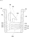
- Fig. 14 shows an example of such a flexible body portion 200.
- the flexible body portion 200 may have less deformable portions 210 and more deformable portions 212.
- the less deformable portions 210 are extending in directions crossing base-side wall portions 60.
- the more deformable portions 212 are extending along the less deformable portions 210 and more likely to be deformed than the less deformable portions 210.
- the more deformable portions 212 may be provided with slits 220. Moreover, the slits 220 are extending along the less deformable portions 210.
- the flexible body portion 200 is more likely to be deformed in a direction from a tip-end-side axial space 84 toward a base-side axial space 80 than when flexible body portion 200 has uniform deformability throughout itself or when less deformable portions 210 and more deformable portions 212 are extending in directions along base-side wall portions 60. Furthermore, bending in a direction orthogonal to the direction is suppressed.
- the flexible body portion 200 is likely to be deformed in the direction from the tip-end-side axial space 84 toward the base-side axial space 80 and the bending of the flexible body portion 200 in the direction orthogonal to the direction is suppressed, the flexible body portion 200 is less likely to deform an injection needle when an injection needle contact portion 66 slides on a side face of the injection needle 24.
- the slits 220 to the more deformable portions 212, it is possible to reduce an amount of material for manufacture.
- the connecting portion 102 may have a portion which is a kind of structural body portion similarly to the flexible body portion and which is different from the flexible body portion in place of the flexible body portion.
- the structural body portion is protruding from an end portion of a bottom plate portion 130 facing an intra-cylinder space 82 (the end portion provided with a bottom curved face 140) toward a base-side axial space 80.
- a specific structure of the structural body portion is not especially restricted.
- a form of the easy sliding portion 112 is not restricted to the form described above.
- an easy sliding portion 112 may be a porous structure which can contain lubricant.
- An easy sliding portion 112 may have a flat face which comes in contact with an injection needle 24.
- the position of the injection needle contact portion 66 is not restricted to the position described above.
- an injection needle contact portion 66 may be disposed in an intra-cylinder space 82.
- a connecting portion 102 may connect a cylinder portion 62 and a force receiving portion 100.
- a form of the injection needle contact portion 66 is not especially restricted.
- different portions of an injection needle contact portion 66 may have different thicknesses.
Landscapes
- Health & Medical Sciences (AREA)
- Engineering & Computer Science (AREA)
- Heart & Thoracic Surgery (AREA)
- Vascular Medicine (AREA)
- Anesthesiology (AREA)
- Biomedical Technology (AREA)
- Hematology (AREA)
- Life Sciences & Earth Sciences (AREA)
- Animal Behavior & Ethology (AREA)
- General Health & Medical Sciences (AREA)
- Public Health (AREA)
- Veterinary Medicine (AREA)
- Environmental & Geological Engineering (AREA)
- Infusion, Injection, And Reservoir Apparatuses (AREA)
Abstract
Description
- The present invention relates to an injection-needle cover.
-
Patent Document 1 discloses a safe injection-needle cover which is extendable with respect to an injection needle. The injection-needle cover is formed by a plurality of rigid segments serially connected by a plurality of intersegment hinges. The rigid segments are disposed around the injection needle, folded upon each other during a medical procedure, and extended at the end of the medical procedure. The extended injection-needle cover protectively sheathes the injection needle. - Patent Document 1: Japanese Translation of PCT Publication No.
2001-515767 - However, the injection-needle cover disclosed in
Patent Document 1 fails to be extended smoothly depending on size of the needle. If the injection-needle cover cannot be extended smoothly, a health practitioner is forced to handle this trouble. If it takes time to handle the trouble, provision of care for a patient may be delayed. The delay in the provision of the care for the patient may be seriously detrimental to the patient in some cases. - If the injection-needle cover disclosed in
Patent Document 1 cannot be extended smoothly and the health practitioner tries to extend the injection-needle cover, it may cause an accident in some cases. As an example of the accident, the health practitioner may accidentally stick himself/herself with the injection needle. Such an accident may cause infection of the health practitioner in some cases. - The present invention has been made to solve the problem. It is an object of the invention to provide an injection-needle cover which can be extended easily and smoothly.
- As a result of hard studies on the problem, the present inventors have found that specific operation of the injection-needle cover obstructs following operation and have achieved the invention. The invention is as follows.
- An injection-needle cover according to a first aspect of the present invention includes:
- a base portion which is fixed to an injection needle protruding face of a syringe, having a cylinder and an injection needle protruding from the cylinder, so as to enclose the injection needle, the injection needle protruding face being a face of the syringe from which the injection needle is protruding from the cylinder;
- a base hinge which is a hinge provided to the base portion;
- a connected portion fitting space forming portion which is connected to the base portion by the base hinge so as to turn about a base axis orthogonal to a central axis of the injection needle and which forms a space where a portion of the injection needle connected to the cylinder is to become fitted;
- a connecting hinge which is a hinge provided to the connected portion fitting space forming portion; and
- an injection needle enclosure portion which is connected to the connected portion fitting space forming portion by the connecting hinge so as to turn about a connection axis parallel to the base axis,
- the injection needle enclosure portion including
- paired base-side wall portions forming a base-side axial space where a portion of the injection needle is to become fitted,
- a cylinder portion which is continuous from the paired base-side wall portions and which forms an intra-cylinder space communicating with the base-side axial space,
- paired tip-end-side wall portions which are continuous from the cylinder portion, which form a tip-end-side axial space where a tip end portion of the injection needle is to become fitted, so that the tip-end-side axial space communicates with the intra-cylinder space, and which are disposed on the opposite side of the cylinder portion from the paired base-side wall portions so that the base-side axial space and the tip-end-side axial space are aligned with each other, and
- an injection needle contact portion disposed at such a position in one of the base-side axial space and the intra-cylinder space as to come in contact with the injection needle when the base hinge opens,
- wherein the injection needle contact portion has
- a force receiving portion which receives a force from the injection needle when the force receiving portion comes in contact with the injection needle and
- a connecting portion which connects the paired base-side wall portions or the cylinder portion to the force receiving portion and
- the force receiving portion has an easy sliding portion which is disposed in an area adjacent to an injection needle and which slides along the injection needle more easily than a case where an edge having an equal coefficient of static friction to a surface of the connecting portion and crossing the injection needle slides , the area being closer to an area on a side of the tip-end-side axial space than a portion, which faces the injection needle after the injection needle becomes fitted in the base-side axial space and the tip-end-side axial space.
- In addition to the structures according to the first aspect, in the injection-needle cover according to a second aspect of the invention,
the easy sliding portion has an injection needle contact zone extending along a direction of movement of the easy sliding portion in opening of the connecting hinge. - In addition to the structures according to the second aspect, in the injection-needle cover according to a third aspect of the invention,
the injection needle contact zone is provided with a curved face extending from one end to the other end of the injection needle contact zone in the direction of the movement of the easy sliding portion in the opening of the connecting hinge. - In addition to the structures according to the first to third aspects, in the injection-needle cover according to a fourth aspect of the invention,
the connected portion fitting space forming portion has amoment receiving portion 44 for receiving moment about the base axis as a turning center. - In addition to the structures according to the first to fourth aspects, in the injection-needle cover according to a fifth aspect of the invention,
the connecting portion has
a bottom plate portion which is disposed in the base-side axial space to be adjacent to a boundary between the base-side axial space and the intra-cylinder space and opposite ends of which are connected to the base-side wall portions and
a structural body portion protruding from an end portion of the bottom plate portion facing the intra-cylinder space toward the base-side axial space and
a curved face is provided to a portion of the bottom plate portion extending from the opposite face from a face facing the base-side axial space to the end portion. - In addition to the structures according to the first to fifth aspects, in the injection-needle cover according to a sixth aspect of the invention,
the connecting portion has a flexible body portion which bends more in a direction from the tip-end-side axial space toward the base-side axial space than in a direction orthogonal to the direction from the tip-end-side axial space toward the base-side axial space when the force receiving portion receives the force from the injection needle. - In addition to the structures according to the sixth aspect, in the injection-needle cover according to a seventh aspect of the invention,
the flexible body portion has a plate-shaped portion disposed to be orthogonal to a bending direction which is the direction from the tip-end-side axial space toward the base-side axial space. - In addition to the structures according to the seventh aspect, in the injection-needle cover according to an eighth aspect of the invention,
the plate-shaped portion faces one of the paired base-side wall portions with a clearance left therebetween and
the force receiving portion faces the one of the paired base-side wall portions, which the plate-shaped portion faces with the clearance left therebetween, with a clearance left therebetween. - In addition to the structures according to the eighth aspect, in the injection-needle cover according to a ninth aspect of the invention,
the injection needle enclosure portion further has a hook portion which is protruding into the base-side axial space and which hooks the injection needle when the injection needle becomes fitted in the base-side axial space and the tip-end-side axial space,
the hook portion has
a columnar portion disposed along the paired base-side wall portions in the base-side axial space,
a detachment preventing portion protruding from the columnar portion toward one of the paired base-side wall portions, and
an inclined face disposed from a tip end portion of the columnar portion to a tip end portion of the detachment preventing portion and inclined with respect to a direction along the paired base-side wall portions, and
the plate-shaped portion is connected to the base-side wall portion, toward which the detachment preventing portion is protruding, and faces the different base-side wall portion from the base-side wall portion, toward which the detachment preventing portion is protruding, with the clearance left therebetween. - In addition to the structures according to the sixth to ninth aspects, in the injection-needle cover according to a tenth aspect of the invention,
the flexible body portion has
a less deformable portion extending in a direction crossing the base-side wall portions and
a more deformable portion extending along the less deformable portion and more deformable than the less deformable portion. - In addition to the structures according to the tenth aspect, in the injection-needle cover according to an eleventh aspect of the invention,
the more deformable portion is provided with a slit extending along the less deformable portion. - According to the aspects of the present invention, it is possible to provide an injection-needle cover which can be extended easily and smoothly.
-
-
Fig. 1 is a view showing an attached state of an injection-needle cover according to an embodiment of the present invention to a syringe. -
Fig. 2 is a view showing a state of the injection-needle cover according to the embodiment of the invention enclosing an injection needle. -
Figs. 3(A) to 3(C) are external views of the injection-needle cover according to the embodiment of the invention. -
Fig. 4 is a perspective view of an injection needle enclosure portion according to the embodiment of the invention. -
Fig. 5 is a sectional view of an injection needle contact portion according to the embodiment of the invention. -
Fig. 6 is a perspective view of an easy sliding portion according to the embodiment of the invention. -
Fig. 7 is an enlarged view ofFig. 3(A) . -
Fig. 8 is a sectional view taken along line A-A inFig. 3(A) . -
Fig. 9 is a view showing a state of the injection-needle cover according to the embodiment of the invention immediately before operation. -
Fig. 10 is a view showing a state of the injection-needle cover according to the embodiment of the invention during the operation. -
Fig. 11 is a view of the injection-needle cover according to the embodiment of the invention during the operation when connecting hinges open insufficiently. -
Fig. 12 is a sectional view of an injection needle contact portion of a comparative injection-needle cover. -
Fig. 13 is a diagram showing evaluation of the injection-needle covers according to the embodiment of the invention. -
Fig. 14 is a view showing a flexible body portion according to a variation of the invention. - With reference to the drawings, an embodiment of the present invention will be described. In the following description, the same parts will be provided with the same reference signs and have the same names and functions and therefore will not be described in detail repeatedly.
-
Fig. 1 is a view showing an attached state of an injection-needle cover 30 according to the embodiment to asyringe 20. As shown inFIG. 1 , the injection-needle cover 30 according to the embodiment is attached to the knownsyringe 20. Before use of thesyringe 20, aninjection needle 24 is covered with acylindrical cover 26. The injection-needle cover 30 according to the embodiment encloses theinjection needle 24 of thesyringe 20 after the use of thesyringe 20.Fig. 2 is a view showing a state of the injection-needle cover 30 according to the embodiment enclosing theinjection needle 24. Thecylindrical cover 26 is removed to use thesyringe 20. In the embodiment, a known cylinder to which the knowninjection needle 24 is attached is referred to as acylinder 22. In the embodiment, theinjection needle 24 and thecylinder 22 to which theinjection needle 24 is attached are collectively referred to as thesyringe 20. -
Figs. 3(A) to 3(C) are external views of the injection-needle cover 30 according to the embodiment of the invention.Fig. 3(A) is a plan view of the injection-needle cover 30 according to the embodiment.Fig. 3(B) is a front view of the injection-needle cover 30 according to the embodiment.Fig. 3(C) is a bottom view of the injection-needle cover 30 according to the embodiment. The injection-needle cover 30 according to the embodiment will be described based onFigs. 3(A) to 3(C) . The injection-needle cover 30 according to the embodiment is made of synthetic resin. The injection-needle cover 30 according to the embodiment includes abase portion 32, paired base hinges 34, a connected portion fittingspace forming portion 36, paired connectinghinges 38, and an injectionneedle enclosure portion 40. In the embodiment, these parts are integrated with each other. - In the embodiment, the
base portion 32 is in an annular shape from opposite ends of whichribs 48 are protruding. In the embodiment, a smooth side face of thebase portion 32 facing an injectionneedle protruding face 28 of thecylinder 22 and the injectionneedle protruding face 28 are integrated with each other by welding. In the embodiment, the welding is achieved by rotating the former while pushing the former against the latter. In this way, thebase portion 32 is fixed to the injectionneedle protruding face 28. The injectionneedle protruding face 28 is a smooth face of thecylinder 22 from which theinjection needle 24 is protruding. Thebase portion 32 is fixed so as to enclose theinjection needle 24. As shown inFig. 3(C) , thebase portion 32 includes retainingportions 42 as well. Fixing lugs 90 (described later) get caught on the retainingportions 42. - The base hinges 34 are hinges provided to the
base portion 32. In the embodiment, the base hinges 34 are continuous with theribs 48 at opposite ends of thebase portion 32. - The connected portion fitting
space forming portion 36 is connected to thebase portion 32 by the base hinges 34. In this way, the connected portion fittingspace forming portion 36 turns about abase axis 52. Thebase axis 52 passes through the base hinges 34 and is orthogonal to acentral axis 50 of the injection-needle cover 30 (thecentral axis 50 passes through a center of the base portion 32). The connected portion fittingspace forming portion 36 forms a space. In the space, a portion of theinjection needle 24 connected to thecylinder 22 is to become fitted (in the embodiment, not only a portion formed by a metal tube but also the connected portion is a part of the injection needle 24). The connected portion fittingspace forming portion 36 includes pairedarm portions 46 and amoment receiving portion 44. Thearm portions 46 connect the base hinges 34 and themoment receiving portion 44. The pairedarm portions 46 are respectively connected to the different base hinges 34. Themoment receiving portion 44 receives moment about thebase axis 52 as a turning center. - The connecting hinges 38 are hinges provided to the connected portion fitting
space forming portion 36 with themoment receiving portion 44 interposed therebetween. - The injection
needle enclosure portion 40 is connected to the connected portion fittingspace forming portion 36 by the paired connecting hinges 38. The injectionneedle enclosure portion 40 turns about aconnection axis 54. Theconnection axis 54 passes through the connecting hinges 38 and is parallel to thebase axis 52. -
Fig. 4 is a perspective view of an injectionneedle enclosure portion 40 according to the embodiment of the invention. The injectionneedle enclosure portion 40 according to the embodiment will be described based onFig. 4 . The injectionneedle enclosure portion 40 according to the embodiment includes paired base-side wall portions 60, acylinder portion 62, paired tip-end-side wall portions 64, an injectionneedle contact portion 66, ahook portion 68, and a needle tipend fixing portion 70. - The paired base-
side wall portions 60 are disposed to face each other. A space between the paired base-side wall portions 60 is a base-sideaxial space 80. In this way, the paired base-side wall portions 60 form the base-sideaxial space 80. In the base-sideaxial space 80, a part of theinjection needle 24 is to become fitted. Each of the base-side wall portions 60 has the fixinglug 90. The fixing lugs 90 pass through the space formed by the connected portion fittingspace forming portion 36 and get caught on the retainingportions 42 of thebase portion 32. As a result, the injection-needle cover 30 according to the embodiment takes the form shown inFig. 1 . - The
cylinder portion 62 is continuous with the paired base-side wall portions 60. Thecylinder portion 62 forms anintra-cylinder space 82. The space surrounded with an inner peripheral face of thecylinder portion 62 is theintra-cylinder space 82. As is clear fromFig. 4 , theintra-cylinder space 82 communicates with the base-sideaxial space 80 through a notch formed in thecylinder portion 62. - The paired tip-end-
side wall portions 64 are disposed to face each other. The paired tip-end-side wall portions 64 are continuous with thecylinder portion 62. A space between the paired tip-end-side wall portions 64 is a tip-end-sideaxial space 84. In this way, the paired tip-end-side wall portions 64 form the tip-end-sideaxial space 84. A tip end portion of theinjection needle 24 is to become fitted in the tip-end-sideaxial space 84. The tip-end-sideaxial space 84 communicates with theintra-cylinder space 82 through a notch formed in thecylinder portion 62. The paired tip-end-side wall portions 64 are disposed on the opposite side of thecylinder portion 62 from the paired base-side wall portions 60. The paired tip-end-side wall portions 64 are disposed so that the base-sideaxial space 80 and the tip-end-sideaxial space 84 are aligned with each other. - In the embodiment, the injection
needle contact portion 66 is disposed at a position in the base-sideaxial space 80 which is a boundary between the base-sideaxial space 80 and theintra-cylinder space 82. - The
hook portion 68 is protruding into the base-sideaxial space 80. Thehook portion 68 according to the embodiment includes acolumnar portion 150, adetachment preventing portion 152, and aninclined face 154. Thecolumnar portion 150 is disposed in the base-sideaxial space 80. Thecolumnar portion 150 is provided along the paired base-side wall portions 60. Thedetachment preventing portion 152 is protruding from thecolumnar portion 150 toward one of the paired base-side wall portions 60. Theinclined face 154 is disposed from a tip end portion of thecolumnar portion 150 to a tip end portion of thedetachment preventing portion 152. Theinclined face 154 is inclined with respect to a direction along the paired base-side wall portions 60. - The needle tip
end fixing portion 70 is protruding from one of the tip-end-side wall portions 64 into the tip-end-sideaxial space 84. Thehook portion 68 and the needle tipend fixing portion 70 catch theinjection needle 24 when theinjection needle 24 becomes fitted into the base-sideaxial space 80 and the tip-end-sideaxial space 84. -
Fig. 5 is a sectional view of an injectionneedle contact portion 66 according to the embodiment.Fig. 5 shows a section of the injectionneedle contact portion 66 along thecentral axis 50 of the injection-needle cover 30. The injectionneedle contact portion 66 according to the embodiment will be described based onFig. 5 . The injectionneedle contact portion 66 according to the embodiment includes aforce receiving portion 100 and a connectingportion 102. In the embodiment, theforce receiving portion 100 and the connectingportion 102 are integrated with each other. - The
force receiving portion 100 receives a force from theinjection needle 24 when theforce receiving portion 100 comes in contact with theinjection needle 24. Theforce receiving portion 100 includes an injectionneedle facing portion 110 and an easy slidingportion 112. - The injection
needle facing portion 110 faces theinjection needle 24 after theinjection needle 24 becomes fitted in the base-sideaxial space 80 and the tip-end-sideaxial space 84. The easy slidingportion 112 is disposed in an area adjacent to the injection needle. In the embodiment, the area adjacent to the injection needle refers to an area of theforce receiving portion 100 on a side closer to theintra-cylinder space 82 and the tip-end-sideaxial space 84 than the injectionneedle facing portion 110. -
Fig. 6 is a perspective view of the easy slidingportion 112 according to the embodiment.Fig. 7 is an enlarged view of an area around a boundary between the base-sideaxial space 80 and theintra-cylinder space 82 inFig. 3(A) .Fig. 8 is a sectional view taken along line A-A inFig. 3(A) . The easy slidingportion 112 according to the embodiment will be described based onFigs. 6 to 8 . The easy slidingportion 112 is a portion which slides more easily along theinjection needle 24 than a case where anedge 114 having an equal coefficient of static friction to the connectingportion 102 and crossing theinjection needle 24 slides along theinjection needle 24. As shown inFigs. 7 and8 , in the embodiment, the easy slidingportion 112 includes an injectionneedle contact zone 120 and paired injection needleposition correcting zones 122. - The injection
needle contact zone 120 is extending along a direction of movement of the easy slidingportion 112 in opening of the connecting hinges 38. This direction is a direction from thehook portion 68 toward the injectionneedle facing portion 110 inFig. 7 . In the embodiment, a curved face is provided throughout the injectionneedle contact zone 120. The curved face extends from one end to the other end of the injectionneedle contact zone 120 in the direction of the movement of the easy slidingportion 112 in the opening of the connecting hinges 38. In the embodiment, a radius of curvature of the curved face equals to a thickness of the injectionneedle contact portion 66 at a base of the force receiving portion 100 (a connection between theforce receiving portion 100 and the connecting portion 102). Needless to say, the radius of curvature may be larger or smaller than the thickness of the injectionneedle contact portion 66. The paired injection needleposition correcting zones 122 are disposed to sandwich the injectionneedle facing portion 110. In the embodiment, the injection needleposition correcting zones 122 are extending in a direction along the inner peripheral face of thecylinder portion 62 as well as in the direction of the movement of the easy slidingportion 112 in the opening of the connecting hinges 38. In this way, when a metal tube portion of theinjection needle 24 bends, the injection needleposition correcting zones 122 can correct the bend. In the embodiment, curved faces are respectively provided throughout the injection needleposition correcting zones 122. In the embodiment, the curved faces and the curved face provided throughout the injectionneedle contact zone 120 are integrated with each other. In this way, it is possible to smoothly correct the bend when the metal tube portion of theinjection needle 24 bends. - In the embodiment, the connecting
portion 102 connects the paired base-side wall portions 60 and theforce receiving portion 100. The connectingportion 102 according to the embodiment will be described based onFigs. 5 ,7 , and8 . In the embodiment, the connectingportion 102 includes abottom plate portion 130 and a plate-shapedportion 132. - In the embodiment, the
bottom plate portion 130 is disposed in the base-sideaxial space 80 to extend from a boundary between the base-sideaxial space 80 and theintra-cylinder space 82 to a vicinity of the connecting hinges 38. As shown inFig. 7 , opposite ends of thebottom plate portion 130 are connected to the base-side wall portions 60. As shown inFig. 5 , thebottom plate portion 130 is provided with a bottomcurved face 140. In the embodiment, one end of the bottomcurved face 140 is positioned on a face of thebottom plate portion 130 facing an outside of the injection-needle cover 30 (i.e., a face opposite from a face facing the base-side axial space 80). The other end of the bottomcurved face 140 faces theintra-cylinder space 82. - As shown in
Fig. 5 , the plate-shapedportion 132 is protruding from the end portion of thebottom plate portion 130 facing the intra-cylinder space 82 (end portion provided with the bottom curved face 140) toward the base-sideaxial space 80. The plate-shapedportion 132 is disposed to be orthogonal to a bending direction. In this case, the bending direction refers to a direction from the tip-end-sideaxial space 84 toward the base-sideaxial space 80. When theforce receiving portion 100 receives a force from theinjection needle 24, the plate-shapedportion 132 bends more in the direction from the tip-end-sideaxial space 84 toward the base-sideaxial space 80 than in the direction orthogonal to the direction from the tip-end-sideaxial space 84 toward the base-sideaxial space 80. An example of "the direction orthogonal to the direction from the tip-end-sideaxial space 84 toward the base-sideaxial space 80" is a direction from one of the paired base-side wall portions 60 toward the other. In the embodiment, the plate-shapedportion 132 is connected to the base-side wall portion 60 toward which thedetachment preventing portion 152 of thehook portion 68 is protruding. As shown inFig. 8 , in the embodiment, the plate-shapedportion 132 faces the different base-side wall portion 60 from the base-side wall portion 60 toward which thedetachment preventing portion 152 is protruding (the base-side wall portion 60 toward which thedetachment preventing portion 152 is not protruding) with aclearance 160 left therebetween. In the embodiment, theforce receiving portion 100 is disposed similarly. Therefore, theforce receiving portion 100 faces the base-side wall portion 60, which the plate-shapedportion 132 faces with theclearance 160 left therebetween, with theclearance 160 therebetween. In the embodiment, theclearance 160 is 1.3 mm in width. The width of theclearance 160 is determined based on the following basis. In other words, a clearance between the paired base-side wall portions 60 is 5.8 mm. An outer diameter of the metal tube portion of theinjection needle 24 is assumed to be between 0.65 mm and 0.50 mm inclusive. An assumed maximum value of the outer diameter of the metal tube portion of theinjection needle 24 is 0.65 mm. If the width of theclearance 160 exceeds a half of the clearance between the paired base-side wall portions 60, theinjection needle 24 may fall into theclearance 160. In order to avoid this, the width of theclearance 160 is preferably not greater than the half of the interval between the paired base-side wall portions 60. It is more preferable that the width of theclearance 160 is not greater than a value obtained by subtracting a half of the outer diameter of theinjection needle 24 from the half of the interval between the paired base-side wall portions 60. The half of the interval between the paired base-side wall portions 60 is 5.8 mm ÷ 2 = 2.9 mm. A half of the assumed maximum value of the outer diameter of theinjection needle 24 is 0.65 mm ÷ 2 = 0.325 mm. 2.9 mm - 0.325 mm = 2.575 mm. Based on this, a maximum value of the width of theclearance 160 is set to 2.575 mm. This corresponds to about 44.4% of the interval between the paired base-side wall portions 60. As a result, the width of theclearance 160 in the embodiment is 1.3 mm. Needless to say, the width of theclearance 160 may be different. -
Fig. 9 is a view showing a state of the injection-needle cover 30 according to the embodiment immediately before operation.Fig. 10 is a view showing a state of the injection-needle cover 30 according to the embodiment during operation. In this view, a part of the injection-needle cover 30 is cut away.Fig. 11 is a view of the injection-needle cover 30 according to the embodiment during the operation when the connecting hinges 38 insufficiently open. In this view, again, a part of the injection-needle cover 30 is cut away. The operation of the injection-needle cover 30 according to the embodiment will be described based onFigs. 9 to 11 . - First, a user takes the
cylindrical cover 26 off thesyringe 20 held in his/her hand. If thecylindrical cover 26 is taken off, the user uses thesyringe 20. A method of using thesyringe 20 is known. Therefore, the method will not be described here in detail. - After use of the
syringe 20 is finished, the user holds thecylinder 22 of thesyringe 20 in his/her hand. At this time, the user lightly touches themoment receiving portion 44 with his/herthumb 170 as shown inFig. 9 . When the user touches themoment receiving portion 44 with his/herthumb 170, the user pushes themoment receiving portion 44 in a direction parallel to theinjection needle 24 with his/herthumb 170. - As the
moment receiving portion 44 is pushed, the fixing lugs 90 caught on the retainingportions 42 are detached from the retainingportions 42. If the fixing lugs 90 are detached from the retainingportions 42, the folded injection-needle cover 30 is naturally extended by resilience of the base hinges 34 and resilience of the connecting hinges 38. The base hinges 34 and the connecting hinges 38 open. As a result, as shown inFig. 10 , the injectionneedle contact zone 120 of the easy slidingportion 112 comes in contact with a connected portion of theinjection needle 24. At this time, the user keeps pushing themoment receiving portion 44 in the direction parallel to theinjection needle 24 with his/herthumb 170. As themoment receiving portion 44 is kept pushed, the injectionneedle contact zone 120 moves along a base portion of theinjection needle 24. A direction of movement of the injectionneedle contact zone 120 at this time is a direction of movement of the easy slidingportion 112 in opening of the connecting hinges 38. - If the connecting hinges 38 open insufficiently when the fixing lugs 90 are detached from the retaining
portions 42, the bottomcurved face 140 first comes in contact with the connected portion of theinjection needle 24 as shown inFig. 11 . The bottomcurved face 140 moves along the connected portion of theinjection needle 24. The direction of movement of the injectionneedle contact zone 120 at this time is also the direction of the movement of the easy slidingportion 112 in the opening of the connecting hinges 38. Then, in place of the bottomcurved face 140, the injectionneedle contact zone 120 of the easy slidingportion 112 comes in contact with the connected portion of theinjection needle 24. - If the injection
needle contact zone 120 of the easy slidingportion 112 moves along the connected portion of theinjection needle 24 in this state, theinjection needle 24 first becomes fitted in the tip-end-sideaxial space 84. The tip end portion of theinjection needle 24 fitted in the tip-end-sideaxial space 84 gets caught on the needle tipend fixing portion 70. Then, theinjection needle 24 becomes fitted in the base-sideaxial space 80. Theinjection needle 24 fitted in the base-sideaxial space 80 gets caught on thehook portion 68. If a vibration caused when thehook portion 68 hooks the tip end portion of theinjection needle 24 is transmitted to the user's hand, the user stops pushing themoment receiving portion 44. At this time, the injection-needle cover 30 protects theinjection needle 24 as shown inFig. 2 . If the injection-needle cover 30 protects theinjection needle 24, the user disposes of thesyringe 20 with the injection-needle cover 30 on it. - In the embodiment, the injection-
needle cover 30 in the folded state is attached to thesyringe 20 in advance. The injection-needle cover 30 is fixed by thebase portion 32 to a face of thesyringe 20 from which theinjection needle 24 is protruding. At this time, theinjection needle 24 passes through theintra-cylinder space 82. The injection-needle cover 30 is extended by sliding the injectionneedle contact portion 66 along a side face of theinjection needle 24. As the injectionneedle contact portion 66 slides along the side face of theinjection needle 24, the portion of theinjection needle 24 connected to thecylinder 22 is housed in the space formed by the connected portion fittingspace forming portion 36. Theinjection needle 24 passing through theintra-cylinder space 82 gradually becomes fitted in the base-sideaxial space 80 and the tip-end-sideaxial space 84. Theinjection needle 24 passes through theintra-cylinder space 82 when theinjection needle 24 becomes fitted in the base-sideaxial space 80 and the tip-end-sideaxial space 84. This is because the base-sideaxial space 80 communicates with theintra-cylinder space 82, theintra-cylinder space 82 communicates with the tip-end-sideaxial space 84, the base-sideaxial space 80 and the tip-end-sideaxial space 84 are aligned with each other, and the paired tip-end-side wall portions 64 are disposed on the opposite side of thecylinder portion 62 from the paired base-side wall portions 60. Before the injectionneedle contact portion 66 starts to slide on the side face of theinjection needle 24, the base hinges 34 open. When the base hinges 34 open, the connected portion fittingspace forming portion 36 turns. When the connected portion fittingspace forming portion 36 turns, the injectionneedle enclosure portion 40 turns as well. This is because the injectionneedle enclosure portion 40 is connected to the connected portion fittingspace forming portion 36 by the connecting hinges 38. When the injectionneedle enclosure portion 40 turns, the injectionneedle contact portion 66 comes in contact with the side face of theinjection needle 24. Unless the connecting hinges 38 open insufficiently, a portion of theforce receiving portion 100 which faces theinjection needle 24 after theinjection needle 24 becomes fitted in the base-sideaxial space 80 and the tip-end-side axial space 84 (i.e., injection needle facing portion 110) and an area on a side of the portion close to the tip-end-sideaxial space 84 come in direct contact with the side face of theinjection needle 24 in many cases. If the connecting hinges 38 open insufficiently, the bottomcurved face 140 rather than the injectionneedle facing portion 110 and the easy slidingportion 112 is likely to come in direct contact with the side face of theinjection needle 24 as shown inFig. 11 when the injectionneedle contact portion 66 starts to slide on the side face of theinjection needle 24. In either case, the base hinges 34 open more than the connecting hinges 38 when the injectionneedle contact portion 66 starts to slide on the side face of theinjection needle 24. Because the base hinges 34 open, the injectionneedle enclosure portion 40 turns. As a result, the injectionneedle contact portion 66 comes in contact with the side face of theinjection needle 24. Because theforce receiving portion 100 has the easy slidingportion 112 and the easy slidingportion 112 is disposed in an area adjacent to the injection needle, theforce receiving portion 100 slides more easily when the injectionneedle contact portion 66 starts to slide on the side face of theinjection needle 24 than the case where theedge 114 having the equal coefficient of static friction to a surface of the connectingportion 102 and crossing theinjection needle 24 slides along theinjection needle 24. Because theforce receiving portion 100 slides easily, the injection-needle cover 30 is likely to be extended smoothly. - When the injection
needle contact portion 66 slides on the side face of theinjection needle 24, the connecting hinges 38 open. The injectionneedle contact zone 120 is extending along the direction of the movement of the easy slidingportion 112 in the opening of the connecting hinges 38. Because the injectionneedle contact zone 120 is a zone provided to the easy slidingportion 112, the easy slidingportion 112 slides on the side face of theinjection needle 24 as the connecting hinges 38 open when the injectionneedle contact portion 66 slides on the side face of theinjection needle 24. In this way, as compared with the case in which the injectionneedle contact zone 120 is not extending along the direction of the movement of the easy slidingportion 112 in the opening of the connecting hinges 38, it is possible to extend the injection-needle cover 30 smoothly for a longer time. - If the curved face is provided from one end to the other end of the injection
needle contact zone 120, as compared with the case in which a plurality of flat faces are arranged in a row, for example, in the injectionneedle contact zone 120, the injectionneedle contact zone 120 smoothly slides on the side face of theinjection needle 24. If the injectionneedle contact zone 120 can slide smoothly, as compared with the case in which the injectionneedle contact zone 120 cannot slide smoothly, it is possible to extend the injection-needle cover 30 smoothly. - If the
moment receiving portion 44 receives the moment, as compared with the case in which a portion of the injection-needle cover 30 other than the connected portion fittingspace forming portion 36 receives moment (e.g., the case in which the moment is applied to the connected portion fittingspace forming portion 36 via the connecting hinges 38 by pinching the tip-end-side wall portions 64 between a thumb and a finger and moving the tip-end-side wall portions 64 in the direction along the injection needle 24), direct contact of the area adjacent to the injection needle with the side face of theinjection needle 24 is facilitated. Because the direct contact of the area adjacent to the injection needle with the side face of theinjection needle 24 is facilitated, the injection-needle cover 30 is more likely to be extended smoothly as compared with the case in which the connected portion fittingspace forming portion 36 does not have themoment receiving portion 44. - Depending on degrees of opening of the connecting hinges 38 when the base hinges 34 start to open, a portion of the
bottom plate portion 130 from the opposite face from a face facing the base-sideaxial space 80 to an end portion facing theintra-cylinder space 82 may come in contact with theinjection needle 24 earlier than the area adjacent to the injection needle in some cases. If this portion is provided with the bottomcurved face 140, even if the portion comes in contact with theinjection needle 24 earlier than the area adjacent to the injection needle, the portion can move smoothly after the contact. - Because the plate-shaped
portion 132 bends when theforce receiving portion 100 receives the force from theinjection needle 24, the injectionneedle contact portion 66 is more likely to start to slide on the side face of theinjection needle 24 than when the plate-shapedportion 132 does not bend. If the injectionneedle contact portion 66 is more likely to start to slide on the side face of theinjection needle 24, the injection-needle cover 30 is move likely to be extended smoothly than when the injectionneedle contact portion 66 is less likely to start to slide. - By increasing a difference between a thickness and a width of the plate-shaped
portion 132, it is possible to easily increase a difference between bendability of the plate-shapedportion 132 in the direction from the tip-end-sideaxial space 84 toward the base-sideaxial space 80 and bendability of the plate-shapedportion 132 in the direction orthogonal to the direction. By increasing the difference in bendability, the plate-shapedportion 132 becomes more likely to bend in the direction from the tip-end-sideaxial space 84 toward the base-sideaxial space 80. As a result, the injection-needle cover 30 becomes more likely to be extended smoothly. - Because the plate-shaped
portion 132 faces one of the paired base-side wall portions 60 with theclearance 160 left therebetween, a portion where theclearance 160 is provided bends easily. If theforce receiving portion 100 similarly has theclearance 160, the plate-shapedportion 132 becomes more likely to bend in the direction from the tip-end-sideaxial space 84 toward the base-sideaxial space 80 than when theforce receiving portion 100 does not have theclearance 160. As a result, the injection-needle cover 30 becomes more likely to be extended smoothly. - If the injection
needle enclosure portion 40 further has thehook portion 68, theinjection needle 24 which has become fitted in the base-sideaxial space 80 and the tip-end-sideaxial space 84 is less likely to be detached than when the injectionneedle enclosure portion 40 does not have thehook portion 68. Moreover, if the plate-shapedportion 132 is connected to the base-side wall portion 60 toward which thedetachment preventing portion 152 is protruding, faces the different base-side wall portion 60 from the base-side wall portion 60, toward which thedetachment preventing portion 152 is protruding, with theclearance 160 left therebetween, and theinclined face 154 is disposed from the tip end portion of thecolumnar portion 150 to the tip end portion of thedetachment preventing portion 152, theinjection needle 24 is less likely to become fitted in theclearance 160 than when such ahook portion 68 does not exist. If theinjection needle 24 is less likely to become fitted in theclearance 160, theinjection needle 24 is less likely to be covered with the injection-needle cover 30. If the injectionneedle enclosure portion 40 further has the needle tipend fixing portion 70, theinjection needle 24 which has become fitted in the base-sideaxial space 80 and the tip-end-sideaxial space 84 is less likely to be detached than when the injectionneedle enclosure portion 40 does not have the needle tipend fixing portion 70. - The injection-
needle cover 30 described by usingFigs. 1 to 11 (hereafter referred to as "the injection-needle cover according to the invention") and a comparative injection-needle cover described below were compared with each other in terms of operation. The comparative injection-needle cover has the same structure as the injection-needle cover according to the invention except the following points. The points are that the comparative injection-needle cover has anedge 114 instead of the easy slidingportion 112 of the injection-needle cover according to the invention and that the comparative injection-needle cover has abottom edge 180 instead of the bottomcurved face 140.Fig. 12 is a sectional view of an injectionneedle contact portion 190 of the comparative injection-needle cover. - An examiner prepared 1100 injection-needle covers according to the invention respectively attached to syringes as first-type samples. As second-type samples, the examiner prepared 1100 comparative injection-needle covers respectively attached to the same kind of syringes as the syringes of the first-type samples. As third-type samples, the examiner prepared 1100 injection-needle covers according to the invention respectively attached to other syringes with thick injection needles. As fourth-type samples, the examiner prepared 1100 comparative injection-needle covers respectively attached to the same kind of syringes as the syringes with the thick injection needles. On request from the examiner, 22 examinees evaluated smoothness of operation of each of the samples. Each of the examinees used 50 samples of each type.
- The smoothness of operation was rated on a three-point scale. If a cover operated very smoothly, the cover was rated as A. If a cover operated to the end while giving a scratchy feeling, the cover was rated as B. If a cover got caught firmly and stopped operating, the cover was rated as C. Results of the evaluation are shown in Table 1. Percentages of A, B, and C ratings given by the respective examinees are shown in
Fig. 13. Fig. 13 shows the percentages of the ratings for each type of samples. Respective percentage bar charts inFig. 13 show the percentages of the ratings by the respective examinees.[Table 1] First type Second type Third type Fourth type Injection-needle cover according to the invention (22 examinees × 50 covers/examinee) Comparative injection-needle cover (22 examinees × 50 covers/examinee) Injection-needle cover according to the invention (22 examinees × 50 covers/examinee) Comparative injection-needle cover (22 examinees × 50 covers/examinee) A rating 84.5% 57.4% 83.6% 60.4% B rating 15.5% 42.0% 16.4% 39.6% C rating 0.0% 0.6% 0.0% 0.0% - As is clear from Table 1, a percentage of A ratings for the first-type samples was 84.5%. A percentage of B ratings for the first-type samples was 15.5%. A percentage of C ratings for the first-type samples was 0.0%. A percentage of A ratings for the second-type samples was 57.4%. A percentage of B ratings for the second-type samples was 42.0%. A percentage of C ratings for the second-type samples was 0.6%. A percentage of A ratings for the third-type samples was 83.6%. A percentage of B ratings for the third-type sample was 16.4%. A percentage of C ratings for the third-type samples was 0%. A percentage of A ratings for the fourth-type samples was 60.4%. A percentage of B ratings for the fourth-type samples was 39.6%. A percentage of C ratings for the fourth-type samples was 0%.
- According to Table 1, the percentage of A ratings for the first-type samples is about 30% higher than the percentage of A ratings for the second-type samples. The percentage of A ratings for the third-type samples is about 20% higher than the percentage of A ratings for the fourth-type samples. From these results, it can be seen that the injection-needle cover according to the invention is much less likely to give a scratchy feeling than the comparative injection-needle cover.
- The embodiment disclosed this time is just one example in every respect. The scope of the invention is not restricted by the above-described embodiment. It is needless to say that the invention can be changed in various ways in design without departing from the gist of the invention.
- For example, the structure of the connecting
portion 102 is not restricted to that described above. The connectingportion 102 may have a portion which is a kind of flexible body portion similarly to the plate-shaped portion but is not in a plate shape in place of the plate-shaped portion. Similarly to the plate-shaped portion, the flexible body portion bends more in a direction from a tip-end-sideaxial space 84 toward a base-sideaxial space 80 than in a direction orthogonal to the direction from the tip-end-sideaxial space 84 toward the base-sideaxial space 80 when aforce receiving portion 100 receives a force from aninjection needle 24. In this case, again, because the flexible body portion bends when theforce receiving portion 100 receives the force from theinjection needle 24, an injectionneedle contact portion 66 becomes more likely to start to slide on a side face of theinjection needle 24 than when the flexible body portion does not bend. If the injectionneedle contact portion 66 is more likely to start to slide on the side face of theinjection needle 24, an injection-needle cover 30 is more likely to be extended smoothly than when the injectionneedle contact portion 66 is less likely to start to slide. A specific structure of the flexible body portion is not especially restricted. For example,Fig. 14 shows an example of such aflexible body portion 200. Theflexible body portion 200 may have lessdeformable portions 210 and moredeformable portions 212. The lessdeformable portions 210 are extending in directions crossing base-side wall portions 60. The moredeformable portions 212 are extending along the lessdeformable portions 210 and more likely to be deformed than the lessdeformable portions 210. The moredeformable portions 212 may be provided withslits 220. Moreover, theslits 220 are extending along the lessdeformable portions 210. In this case, if the lessdeformable portions 210 and the moredeformable portions 212 are extending in the directions crossing the base-side wall portions 60, theflexible body portion 200 is more likely to be deformed in a direction from a tip-end-sideaxial space 84 toward a base-sideaxial space 80 than whenflexible body portion 200 has uniform deformability throughout itself or when lessdeformable portions 210 and moredeformable portions 212 are extending in directions along base-side wall portions 60. Furthermore, bending in a direction orthogonal to the direction is suppressed. Because theflexible body portion 200 is likely to be deformed in the direction from the tip-end-sideaxial space 84 toward the base-sideaxial space 80 and the bending of theflexible body portion 200 in the direction orthogonal to the direction is suppressed, theflexible body portion 200 is less likely to deform an injection needle when an injectionneedle contact portion 66 slides on a side face of theinjection needle 24. Moreover, by providing theslits 220 to the moredeformable portions 212, it is possible to reduce an amount of material for manufacture. Besides the flexible body portion shown inFig. 14 , it is also possible to employ a flexible body portion having slits (and lessdeformable portions 210 and more deformable portions 212) extending in directions different from those shown inFig. 14 or a flexible body portion having circular holes instead of slits. The connectingportion 102 may have a portion which is a kind of structural body portion similarly to the flexible body portion and which is different from the flexible body portion in place of the flexible body portion. The structural body portion is protruding from an end portion of abottom plate portion 130 facing an intra-cylinder space 82 (the end portion provided with a bottom curved face 140) toward a base-sideaxial space 80. A specific structure of the structural body portion is not especially restricted. - A form of the easy sliding
portion 112 is not restricted to the form described above. For example, an easy slidingportion 112 may be a porous structure which can contain lubricant. An easy slidingportion 112 may have a flat face which comes in contact with aninjection needle 24. - The position of the injection
needle contact portion 66 is not restricted to the position described above. For example, an injectionneedle contact portion 66 may be disposed in anintra-cylinder space 82. In this case, a connectingportion 102 may connect acylinder portion 62 and aforce receiving portion 100. A form of the injectionneedle contact portion 66 is not especially restricted. For example, different portions of an injectionneedle contact portion 66 may have different thicknesses. - In this paragraph, an invention different from the present invention will be mentioned. In the invention described in this paragraph, it is essential only that a connecting portion have a flexible body portion and a force receiving portion may not have an easy sliding portion. In this case, if the connecting portion has the flexible body portion, the injection-
needle cover 30 becomes more likely to be extended smoothly. In other respects, the invention described in this paragraph is similar to the present invention, i.e., the invention described in paragraphs earlier than this paragraph. -
- 20:
- Syringe
- 22:
- Cylinder
- 24:
- Injection needle
- 26:
- Cylindrical cover
- 28:
- Injection needle protruding face
- 30:
- Injection-needle cover
- 32:
- Base portion
- 34:
- Base hinge
- 36:
- Connected portion fitting space forming portion
- 38:
- Connecting hinge
- 40:
- Injection needle enclosure portion
- 42:
- Retaining portion
- 44:
- Moment receiving portion
- 46:
- Arm portion
- 48:
- Rib
- 50:
- Central axis
- 52:
- Base axis
- 54:
- Connection axis
- 60:
- Base-side wall portion
- 62:
- Cylinder portion
- 64:
- Tip-end-side wall portion
- 66:
- Injection needle contact portion
- 68:
- Hook portion
- 70:
- Needle tip end fixing portion
- 80:
- Base-side axial space
- 82:
- Intra-cylinder space
- 84:
- Tip-end-side axial space
- 90:
- Fixing lug
- 100:
- Force receiving portion
- 102:
- Connecting portion
- 110:
- Injection needle facing portion
- 112:
- Easy sliding portion
- 114:
- Edge
- 120:
- Injection needle contact zone
- 122:
- Injection needle position correcting zone
- 130:
- Bottom plate portion
- 132:
- Plate-shaped portion
- 140:
- Bottom curved face
- 150:
- Columnar portion
- 152:
- Detachment preventing portion
- 154:
- Inclined face
- 160:
- Clearance
- 170:
- Thumb
- 180:
- Bottom edge
- 190:
- Injection needle contact portion
- 210:
- Less deformable portion
- 212:
- More deformable portion
- 220:
- Slit
Claims (11)
- An injection-needle cover comprising:a base portion which is fixed to an injection needle protruding face of a syringe, having a cylinder and an injection needle protruding from the cylinder, so as to enclose the injection needle, the injection needle protruding face being a face of the syringe from which the injection needle is protruding from the cylinder;a base hinge which is a hinge provided to the base portion;a connected portion fitting space forming portion which is connected to the base portion by the base hinge so as to turn about a base axis orthogonal to a central axis of the injection needle and which forms a space where a portion of the injection needle connected to the cylinder is to become fitted;a connecting hinge which is a hinge provided to the connected portion fitting space forming portion; andan injection needle enclosure portion which is connected to the connected portion fitting space forming portion by the connecting hinge so as to turn about a connection axis parallel to the base axis,the injection needle enclosure portion includingpaired base-side wall portions forming a base-side axial space where a portion of the injection needle is to become fitted,a cylinder portion which is continuous from the paired base-side wall portions and which forms an intra-cylinder space communicating with the base-side axial space,paired tip-end-side wall portions which are continuous from the cylinder portion, which form a tip-end-side axial space where a tip end portion of the injection needle is to become fitted, so that the tip-end-side axial space communicates with the intra-cylinder space, and which are disposed on the opposite side of the cylinder portion from the paired base-side wall portions so that the base-side axial space and the tip-end-side axial space are aligned with each other, andan injection needle contact portion disposed at such a position in one of the base-side axial space and the intra-cylinder space as to come in contact with the injection needle when the base hinge opens,wherein the injection needle contact portion hasa force receiving portion which receives a force from the injection needle when the force receiving portion comes in contact with the injection needle anda connecting portion which connects the paired base-side wall portions or the cylinder portion to the force receiving portion andthe force receiving portion has an easy sliding portion which is disposed in an area adjacent to an injection needle and which slides along the injection needle more easily than a case where an edge having an equal coefficient of static friction to a surface of the connecting portion and crossing the injection needle slides along the injection needle, the area being closer to an area on a side of the tip-end-side axial space than a portion, which faces the injection needle after the injection needle becomes fitted in the base-side axial space and the tip-end-side axial space.
- The injection-needle cover according to claim 1, wherein the easy sliding portion has an injection needle contact zone extending along a direction of movement of the easy sliding portion in opening of the connecting hinge.
- The injection-needle cover according to claim 2, wherein the injection needle contact zone is provided with a curved face extending from one end to the other end of the injection needle contact zone in the direction of the movement of the easy sliding portion in the opening of the connecting hinge.
- The injection-needle cover according to any one of claims 1 to 3, wherein the connected portion fitting space forming portion has a moment receiving portion for receiving moment about the base axis as a turning center.
- The injection-needle cover according to any one of claims 1 to 4, wherein the connecting portion has
a bottom plate portion which is disposed in the base-side axial space to be adjacent to a boundary between the base-side axial space and the intra-cylinder space and opposite ends of which are connected to the base-side wall portions and
a structural body portion protruding from an end portion of the bottom plate portion facing the intra-cylinder space toward the base-side axial space and
a curved face is provided to a portion of the bottom plate portion extending from the opposite face from a face facing the base-side axial space to the end portion. - The injection-needle cover according to any one of claims 1 to 5, wherein the connecting portion has a flexible body portion which bends more in a direction from the tip-end-side axial space toward the base-side axial space than in a direction orthogonal to the direction from the tip-end-side axial space toward the base-side axial space when the force receiving portion receives the force from the injection needle.
- The injection-needle cover according to claim 6, wherein the flexible body portion has a plate-shaped portion disposed to be orthogonal to a bending direction which is the direction from the tip-end-side axial space toward the base-side axial space.
- The injection-needle cover according to claim 7,
wherein the plate-shaped portion faces one of the paired base-side wall portions with a clearance left therebetween and
the force receiving portion faces the one of the paired base-side wall portions, which the plate-shaped portion faces with the clearance left therebetween, with a clearance left therebetween. - The injection-needle cover according to claim 8,
wherein the injection needle enclosure portion further has a hook portion which is protruding into the base-side axial space and which hooks the injection needle when the injection needle becomes fitted in the base-side axial space and the tip-end-side axial space,
the hook portion has
a columnar portion disposed along the paired base-side wall portions in the base-side axial space,
a detachment preventing portion protruding from the columnar portion toward one of the paired base-side wall portions, and
an inclined face disposed from a tip end portion of the columnar portion to a tip end portion of the detachment preventing portion and inclined with respect to a direction along the paired base-side wall portions, and
the plate-shaped portion is connected to the base-side wall portion, toward which the detachment preventing portion is protruding, and faces the different base-side wall portion from the base-side wall portion, toward which the detachment preventing portion is protruding, with the clearance left therebetween. - The injection-needle cover according to any one of claims 6 to 9,
wherein the flexible body portion has
a less deformable portion extending in a direction crossing the base-side wall portions and
a more deformable portion extending along the less deformable portion and more deformable than the less deformable portion. - The injection-needle cover according to claim 10, wherein the more deformable portion is provided with a slit extending along the less deformable portion.
Applications Claiming Priority (2)
| Application Number | Priority Date | Filing Date | Title |
|---|---|---|---|
| JP2014257759 | 2014-12-19 | ||
| PCT/JP2015/085393 WO2016098861A1 (en) | 2014-12-19 | 2015-12-17 | Injection-needle cover |
Publications (4)
| Publication Number | Publication Date |
|---|---|
| EP3235532A1 true EP3235532A1 (en) | 2017-10-25 |
| EP3235532A4 EP3235532A4 (en) | 2018-07-18 |
| EP3235532B1 EP3235532B1 (en) | 2019-07-31 |
| EP3235532B8 EP3235532B8 (en) | 2019-09-18 |
Family
ID=56126744
Family Applications (1)
| Application Number | Title | Priority Date | Filing Date |
|---|---|---|---|
| EP15870063.3A Active EP3235532B8 (en) | 2014-12-19 | 2015-12-17 | Injection-needle cover |
Country Status (6)
| Country | Link |
|---|---|
| US (1) | US10357618B2 (en) |
| EP (1) | EP3235532B8 (en) |
| JP (1) | JP6588466B2 (en) |
| CN (1) | CN106999676B (en) |
| ES (1) | ES2748704T3 (en) |
| WO (1) | WO2016098861A1 (en) |
Families Citing this family (2)
| Publication number | Priority date | Publication date | Assignee | Title |
|---|---|---|---|---|
| EP3607983B1 (en) * | 2017-04-05 | 2024-12-11 | Takeda Pharmaceutical Company Limited | Syringe |
| WO2021011244A1 (en) * | 2019-07-12 | 2021-01-21 | Becton, Dickinson And Company | Syringe tip cap |
Family Cites Families (10)
| Publication number | Priority date | Publication date | Assignee | Title |
|---|---|---|---|---|
| US5232454A (en) | 1990-08-01 | 1993-08-03 | Smiths Industries Medical Systems, Inc. | Safety needle container |
| US5348544A (en) * | 1993-11-24 | 1994-09-20 | Becton, Dickinson And Company | Single-handedly actuatable safety shield for needles |
| US5823997A (en) * | 1995-01-10 | 1998-10-20 | Specialized Health Products, Inc. | Medical needle safety apparatus and methods |
| US8226617B2 (en) * | 1999-11-04 | 2012-07-24 | Tyco Healthcare Group Lp | Safety shield apparatus and mounting structure for use with medical needle devices |
| US7029461B2 (en) * | 1999-11-04 | 2006-04-18 | Tyco Healthcare Group Lp | Safety shield for medical needles |
| US7198618B2 (en) * | 1999-11-04 | 2007-04-03 | Tyco Healthcare Group Lp | Safety shield for medical needles |
| US6280420B1 (en) * | 1999-11-04 | 2001-08-28 | Specialized Health Products | Reaccessible medical needle safety devices and methods |
| US7361159B2 (en) * | 2001-03-02 | 2008-04-22 | Covidien Ag | Passive safety shield |
| US7001363B2 (en) | 2002-04-05 | 2006-02-21 | F. Mark Ferguson | Safety shield for medical needles |
| US7938800B2 (en) * | 2008-05-13 | 2011-05-10 | Lawrence R. Koh and Nina Merrell-Koh | Needleshield assembly and methods of use |
-
2015
- 2015-12-17 WO PCT/JP2015/085393 patent/WO2016098861A1/en not_active Ceased
- 2015-12-17 JP JP2016564906A patent/JP6588466B2/en active Active
- 2015-12-17 ES ES15870063T patent/ES2748704T3/en active Active
- 2015-12-17 US US15/535,186 patent/US10357618B2/en active Active
- 2015-12-17 EP EP15870063.3A patent/EP3235532B8/en active Active
- 2015-12-17 CN CN201580063511.0A patent/CN106999676B/en active Active
Also Published As
| Publication number | Publication date |
|---|---|
| CN106999676A (en) | 2017-08-01 |
| CN106999676B (en) | 2020-01-31 |
| JP6588466B2 (en) | 2019-10-09 |
| US10357618B2 (en) | 2019-07-23 |
| WO2016098861A1 (en) | 2016-06-23 |
| EP3235532B8 (en) | 2019-09-18 |
| ES2748704T3 (en) | 2020-03-17 |
| US20170326307A1 (en) | 2017-11-16 |
| JPWO2016098861A1 (en) | 2017-11-02 |
| EP3235532B1 (en) | 2019-07-31 |
| EP3235532A4 (en) | 2018-07-18 |
Similar Documents
| Publication | Publication Date | Title |
|---|---|---|
| CN209036593U (en) | Hair diced system and attachment | |
| JP4998165B2 (en) | Medical needle device | |
| JP2000116768A (en) | Puncture appliance | |
| EP3235532B1 (en) | Injection-needle cover | |
| US8535273B2 (en) | Device for removing a huber needle from a patient | |
| HK1252507A1 (en) | Syringe | |
| US8512233B2 (en) | Curved laryngoscope and operation instrument assembly applying the same | |
| JP4608603B1 (en) | Medical needle | |
| EP3607983B1 (en) | Syringe | |
| EP3269411A1 (en) | Needle puncture device | |
| EP4552669A1 (en) | Needle tip protector for winged needles | |
| KR20250088031A (en) | Non-sterile puncture needle containing assembly-enhancing structures | |
| US10842930B2 (en) | Device for infusing a fluid substance to the body of a living being | |
| KR101910189B1 (en) | Guide for fixing of bone fracture and manufacturing method of the same | |
| JPS6068866A (en) | Catheter unit with wing for dripping cannula | |
| CN216135226U (en) | Acupuncture protection device | |
| CN216568526U (en) | Protective gloves | |
| CN209898339U (en) | Novel wrist protective sleeve | |
| JP2007195827A (en) | Safety needle assembly having a curved portion | |
| CN219397499U (en) | Puncture needle | |
| EP4658348A2 (en) | Needle guard | |
| JP7808281B2 (en) | needle assembly | |
| CN213554493U (en) | Insulin needle | |
| EP3275484A1 (en) | Protective element for medical needle assemblies | |
| CN115137439A (en) | Distal end radial artery fixing compression hemostasis device |
Legal Events
| Date | Code | Title | Description |
|---|---|---|---|
| STAA | Information on the status of an ep patent application or granted ep patent |
Free format text: STATUS: THE INTERNATIONAL PUBLICATION HAS BEEN MADE |
|
| PUAI | Public reference made under article 153(3) epc to a published international application that has entered the european phase |
Free format text: ORIGINAL CODE: 0009012 |
|
| STAA | Information on the status of an ep patent application or granted ep patent |
Free format text: STATUS: REQUEST FOR EXAMINATION WAS MADE |
|
| 17P | Request for examination filed |
Effective date: 20170719 |
|
| AK | Designated contracting states |
Kind code of ref document: A1 Designated state(s): AL AT BE BG CH CY CZ DE DK EE ES FI FR GB GR HR HU IE IS IT LI LT LU LV MC MK MT NL NO PL PT RO RS SE SI SK SM TR |
|
| AX | Request for extension of the european patent |
Extension state: BA ME |
|
| RIN1 | Information on inventor provided before grant (corrected) |
Inventor name: CHUMA, YUSUKE Inventor name: OKAJIMA, KIYOSHI Inventor name: IMANISHI, YUKI Inventor name: ASAKAWA, NAOKI Inventor name: TANAKA, NOBUO |
|
| DAV | Request for validation of the european patent (deleted) | ||
| DAX | Request for extension of the european patent (deleted) | ||
| A4 | Supplementary search report drawn up and despatched |
Effective date: 20180619 |
|
| RIC1 | Information provided on ipc code assigned before grant |
Ipc: A61M 5/32 20060101AFI20180613BHEP |
|
| GRAP | Despatch of communication of intention to grant a patent |
Free format text: ORIGINAL CODE: EPIDOSNIGR1 |
|
| STAA | Information on the status of an ep patent application or granted ep patent |
Free format text: STATUS: GRANT OF PATENT IS INTENDED |
|
| INTG | Intention to grant announced |
Effective date: 20190301 |
|
| INTG | Intention to grant announced |
Effective date: 20190306 |
|
| GRAS | Grant fee paid |
Free format text: ORIGINAL CODE: EPIDOSNIGR3 |
|
| GRAA | (expected) grant |
Free format text: ORIGINAL CODE: 0009210 |
|
| STAA | Information on the status of an ep patent application or granted ep patent |
Free format text: STATUS: THE PATENT HAS BEEN GRANTED |
|
| AK | Designated contracting states |
Kind code of ref document: B1 Designated state(s): AL AT BE BG CH CY CZ DE DK EE ES FI FR GB GR HR HU IE IS IT LI LT LU LV MC MK MT NL NO PL PT RO RS SE SI SK SM TR |
|
| RAP1 | Party data changed (applicant data changed or rights of an application transferred) |
Owner name: ARTE CORPORATION Owner name: YOSHINO KOGYOSHO CO., LTD. Owner name: TAKEDA PHARMACEUTICAL COMPANY LIMITED |
|
| REG | Reference to a national code |
Ref country code: CH Ref legal event code: EP Ref country code: GB Ref legal event code: FG4D |
|
| REG | Reference to a national code |
Ref country code: AT Ref legal event code: REF Ref document number: 1160274 Country of ref document: AT Kind code of ref document: T Effective date: 20190815 |
|
| REG | Reference to a national code |
Ref country code: IE Ref legal event code: FG4D |
|
| REG | Reference to a national code |
Ref country code: DE Ref legal event code: R096 Ref document number: 602015035023 Country of ref document: DE |
|
| REG | Reference to a national code |
Ref country code: CH Ref legal event code: PK Free format text: BERICHTIGUNG B8 |
|
| RAP2 | Party data changed (patent owner data changed or rights of a patent transferred) |
Owner name: ARTE CORPORATION Owner name: YOSHINO KOGYOSHO CO., LTD. Owner name: TAKEDA PHARMACEUTICAL COMPANY LIMITED |
|
| REG | Reference to a national code |
Ref country code: NL Ref legal event code: MP Effective date: 20190731 |
|
| REG | Reference to a national code |
Ref country code: LT Ref legal event code: MG4D |
|
| REG | Reference to a national code |
Ref country code: AT Ref legal event code: MK05 Ref document number: 1160274 Country of ref document: AT Kind code of ref document: T Effective date: 20190731 |
|
| PG25 | Lapsed in a contracting state [announced via postgrant information from national office to epo] |
Ref country code: LT Free format text: LAPSE BECAUSE OF FAILURE TO SUBMIT A TRANSLATION OF THE DESCRIPTION OR TO PAY THE FEE WITHIN THE PRESCRIBED TIME-LIMIT Effective date: 20190731 Ref country code: HR Free format text: LAPSE BECAUSE OF FAILURE TO SUBMIT A TRANSLATION OF THE DESCRIPTION OR TO PAY THE FEE WITHIN THE PRESCRIBED TIME-LIMIT Effective date: 20190731 Ref country code: NO Free format text: LAPSE BECAUSE OF FAILURE TO SUBMIT A TRANSLATION OF THE DESCRIPTION OR TO PAY THE FEE WITHIN THE PRESCRIBED TIME-LIMIT Effective date: 20191031 Ref country code: BG Free format text: LAPSE BECAUSE OF FAILURE TO SUBMIT A TRANSLATION OF THE DESCRIPTION OR TO PAY THE FEE WITHIN THE PRESCRIBED TIME-LIMIT Effective date: 20191031 Ref country code: AT Free format text: LAPSE BECAUSE OF FAILURE TO SUBMIT A TRANSLATION OF THE DESCRIPTION OR TO PAY THE FEE WITHIN THE PRESCRIBED TIME-LIMIT Effective date: 20190731 Ref country code: NL Free format text: LAPSE BECAUSE OF FAILURE TO SUBMIT A TRANSLATION OF THE DESCRIPTION OR TO PAY THE FEE WITHIN THE PRESCRIBED TIME-LIMIT Effective date: 20190731 Ref country code: PT Free format text: LAPSE BECAUSE OF FAILURE TO SUBMIT A TRANSLATION OF THE DESCRIPTION OR TO PAY THE FEE WITHIN THE PRESCRIBED TIME-LIMIT Effective date: 20191202 Ref country code: FI Free format text: LAPSE BECAUSE OF FAILURE TO SUBMIT A TRANSLATION OF THE DESCRIPTION OR TO PAY THE FEE WITHIN THE PRESCRIBED TIME-LIMIT Effective date: 20190731 Ref country code: SE Free format text: LAPSE BECAUSE OF FAILURE TO SUBMIT A TRANSLATION OF THE DESCRIPTION OR TO PAY THE FEE WITHIN THE PRESCRIBED TIME-LIMIT Effective date: 20190731 |
|
| PG25 | Lapsed in a contracting state [announced via postgrant information from national office to epo] |
Ref country code: RS Free format text: LAPSE BECAUSE OF FAILURE TO SUBMIT A TRANSLATION OF THE DESCRIPTION OR TO PAY THE FEE WITHIN THE PRESCRIBED TIME-LIMIT Effective date: 20190731 Ref country code: LV Free format text: LAPSE BECAUSE OF FAILURE TO SUBMIT A TRANSLATION OF THE DESCRIPTION OR TO PAY THE FEE WITHIN THE PRESCRIBED TIME-LIMIT Effective date: 20190731 Ref country code: AL Free format text: LAPSE BECAUSE OF FAILURE TO SUBMIT A TRANSLATION OF THE DESCRIPTION OR TO PAY THE FEE WITHIN THE PRESCRIBED TIME-LIMIT Effective date: 20190731 Ref country code: GR Free format text: LAPSE BECAUSE OF FAILURE TO SUBMIT A TRANSLATION OF THE DESCRIPTION OR TO PAY THE FEE WITHIN THE PRESCRIBED TIME-LIMIT Effective date: 20191101 |
|
| REG | Reference to a national code |
Ref country code: ES Ref legal event code: FG2A Ref document number: 2748704 Country of ref document: ES Kind code of ref document: T3 Effective date: 20200317 |
|
| PG25 | Lapsed in a contracting state [announced via postgrant information from national office to epo] |
Ref country code: TR Free format text: LAPSE BECAUSE OF FAILURE TO SUBMIT A TRANSLATION OF THE DESCRIPTION OR TO PAY THE FEE WITHIN THE PRESCRIBED TIME-LIMIT Effective date: 20190731 |
|
| PG25 | Lapsed in a contracting state [announced via postgrant information from national office to epo] |
Ref country code: DK Free format text: LAPSE BECAUSE OF FAILURE TO SUBMIT A TRANSLATION OF THE DESCRIPTION OR TO PAY THE FEE WITHIN THE PRESCRIBED TIME-LIMIT Effective date: 20190731 Ref country code: PL Free format text: LAPSE BECAUSE OF FAILURE TO SUBMIT A TRANSLATION OF THE DESCRIPTION OR TO PAY THE FEE WITHIN THE PRESCRIBED TIME-LIMIT Effective date: 20190731 Ref country code: EE Free format text: LAPSE BECAUSE OF FAILURE TO SUBMIT A TRANSLATION OF THE DESCRIPTION OR TO PAY THE FEE WITHIN THE PRESCRIBED TIME-LIMIT Effective date: 20190731 Ref country code: RO Free format text: LAPSE BECAUSE OF FAILURE TO SUBMIT A TRANSLATION OF THE DESCRIPTION OR TO PAY THE FEE WITHIN THE PRESCRIBED TIME-LIMIT Effective date: 20190731 |
|
| PG25 | Lapsed in a contracting state [announced via postgrant information from national office to epo] |
Ref country code: SK Free format text: LAPSE BECAUSE OF FAILURE TO SUBMIT A TRANSLATION OF THE DESCRIPTION OR TO PAY THE FEE WITHIN THE PRESCRIBED TIME-LIMIT Effective date: 20190731 Ref country code: IS Free format text: LAPSE BECAUSE OF FAILURE TO SUBMIT A TRANSLATION OF THE DESCRIPTION OR TO PAY THE FEE WITHIN THE PRESCRIBED TIME-LIMIT Effective date: 20200224 Ref country code: CZ Free format text: LAPSE BECAUSE OF FAILURE TO SUBMIT A TRANSLATION OF THE DESCRIPTION OR TO PAY THE FEE WITHIN THE PRESCRIBED TIME-LIMIT Effective date: 20190731 Ref country code: SM Free format text: LAPSE BECAUSE OF FAILURE TO SUBMIT A TRANSLATION OF THE DESCRIPTION OR TO PAY THE FEE WITHIN THE PRESCRIBED TIME-LIMIT Effective date: 20190731 |
|
| REG | Reference to a national code |
Ref country code: DE Ref legal event code: R097 Ref document number: 602015035023 Country of ref document: DE |
|
| PLBE | No opposition filed within time limit |
Free format text: ORIGINAL CODE: 0009261 |
|
| STAA | Information on the status of an ep patent application or granted ep patent |
Free format text: STATUS: NO OPPOSITION FILED WITHIN TIME LIMIT |
|
| PG2D | Information on lapse in contracting state deleted |
Ref country code: IS |
|
| PG25 | Lapsed in a contracting state [announced via postgrant information from national office to epo] |
Ref country code: IS Free format text: LAPSE BECAUSE OF FAILURE TO SUBMIT A TRANSLATION OF THE DESCRIPTION OR TO PAY THE FEE WITHIN THE PRESCRIBED TIME-LIMIT Effective date: 20191030 |
|
| 26N | No opposition filed |
Effective date: 20200603 |
|
| REG | Reference to a national code |
Ref country code: BE Ref legal event code: MM Effective date: 20191231 |
|
| PG25 | Lapsed in a contracting state [announced via postgrant information from national office to epo] |
Ref country code: SI Free format text: LAPSE BECAUSE OF FAILURE TO SUBMIT A TRANSLATION OF THE DESCRIPTION OR TO PAY THE FEE WITHIN THE PRESCRIBED TIME-LIMIT Effective date: 20190731 Ref country code: MC Free format text: LAPSE BECAUSE OF FAILURE TO SUBMIT A TRANSLATION OF THE DESCRIPTION OR TO PAY THE FEE WITHIN THE PRESCRIBED TIME-LIMIT Effective date: 20190731 |
|
| PG25 | Lapsed in a contracting state [announced via postgrant information from national office to epo] |
Ref country code: IE Free format text: LAPSE BECAUSE OF NON-PAYMENT OF DUE FEES Effective date: 20191217 Ref country code: LU Free format text: LAPSE BECAUSE OF NON-PAYMENT OF DUE FEES Effective date: 20191217 |
|
| PG25 | Lapsed in a contracting state [announced via postgrant information from national office to epo] |
Ref country code: BE Free format text: LAPSE BECAUSE OF NON-PAYMENT OF DUE FEES Effective date: 20191231 |
|
| PG25 | Lapsed in a contracting state [announced via postgrant information from national office to epo] |
Ref country code: CY Free format text: LAPSE BECAUSE OF FAILURE TO SUBMIT A TRANSLATION OF THE DESCRIPTION OR TO PAY THE FEE WITHIN THE PRESCRIBED TIME-LIMIT Effective date: 20190731 |
|
| PG25 | Lapsed in a contracting state [announced via postgrant information from national office to epo] |
Ref country code: HU Free format text: LAPSE BECAUSE OF FAILURE TO SUBMIT A TRANSLATION OF THE DESCRIPTION OR TO PAY THE FEE WITHIN THE PRESCRIBED TIME-LIMIT; INVALID AB INITIO Effective date: 20151217 Ref country code: MT Free format text: LAPSE BECAUSE OF FAILURE TO SUBMIT A TRANSLATION OF THE DESCRIPTION OR TO PAY THE FEE WITHIN THE PRESCRIBED TIME-LIMIT Effective date: 20190731 |
|
| PG25 | Lapsed in a contracting state [announced via postgrant information from national office to epo] |
Ref country code: MK Free format text: LAPSE BECAUSE OF FAILURE TO SUBMIT A TRANSLATION OF THE DESCRIPTION OR TO PAY THE FEE WITHIN THE PRESCRIBED TIME-LIMIT Effective date: 20190731 |
|
| P01 | Opt-out of the competence of the unified patent court (upc) registered |
Effective date: 20230530 |
|
| REG | Reference to a national code |
Ref country code: CH Ref legal event code: U11 Free format text: ST27 STATUS EVENT CODE: U-0-0-U10-U11 (AS PROVIDED BY THE NATIONAL OFFICE) Effective date: 20260101 |
|
| PGFP | Annual fee paid to national office [announced via postgrant information from national office to epo] |
Ref country code: DE Payment date: 20251209 Year of fee payment: 11 |
|
| PGFP | Annual fee paid to national office [announced via postgrant information from national office to epo] |
Ref country code: GB Payment date: 20251210 Year of fee payment: 11 |
|
| PGFP | Annual fee paid to national office [announced via postgrant information from national office to epo] |
Ref country code: IT Payment date: 20251215 Year of fee payment: 11 |
|
| PGFP | Annual fee paid to national office [announced via postgrant information from national office to epo] |
Ref country code: FR Payment date: 20251210 Year of fee payment: 11 |
|
| PGFP | Annual fee paid to national office [announced via postgrant information from national office to epo] |
Ref country code: ES Payment date: 20260102 Year of fee payment: 11 |
|
| PGFP | Annual fee paid to national office [announced via postgrant information from national office to epo] |
Ref country code: CH Payment date: 20260101 Year of fee payment: 11 |