EP3235367A1 - Baler with improved cross member for mounting the gearbox - Google Patents
Baler with improved cross member for mounting the gearbox Download PDFInfo
- Publication number
- EP3235367A1 EP3235367A1 EP17157827.1A EP17157827A EP3235367A1 EP 3235367 A1 EP3235367 A1 EP 3235367A1 EP 17157827 A EP17157827 A EP 17157827A EP 3235367 A1 EP3235367 A1 EP 3235367A1
- Authority
- EP
- European Patent Office
- Prior art keywords
- cross member
- baler
- gearbox
- coupling flange
- frame
- Prior art date
- Legal status (The legal status is an assumption and is not a legal conclusion. Google has not performed a legal analysis and makes no representation as to the accuracy of the status listed.)
- Granted
Links
Images

Classifications
-
- A—HUMAN NECESSITIES
- A01—AGRICULTURE; FORESTRY; ANIMAL HUSBANDRY; HUNTING; TRAPPING; FISHING
- A01F—PROCESSING OF HARVESTED PRODUCE; HAY OR STRAW PRESSES; DEVICES FOR STORING AGRICULTURAL OR HORTICULTURAL PRODUCE
- A01F15/00—Baling presses for straw, hay or the like
- A01F15/08—Details
-
- A—HUMAN NECESSITIES
- A01—AGRICULTURE; FORESTRY; ANIMAL HUSBANDRY; HUNTING; TRAPPING; FISHING
- A01F—PROCESSING OF HARVESTED PRODUCE; HAY OR STRAW PRESSES; DEVICES FOR STORING AGRICULTURAL OR HORTICULTURAL PRODUCE
- A01F15/00—Baling presses for straw, hay or the like
- A01F15/08—Details
- A01F15/0841—Drives for balers
-
- B—PERFORMING OPERATIONS; TRANSPORTING
- B30—PRESSES
- B30B—PRESSES IN GENERAL
- B30B9/00—Presses specially adapted for particular purposes
- B30B9/30—Presses specially adapted for particular purposes for baling; Compression boxes therefor
- B30B9/306—Mechanically-driven presses
Definitions
- the present invention relates to balers comprising a frame, a gearbox, and a cross member extending in the transverse direction for coupling a top part of the gearbox to the frame. More in particular the invention relates to rectangular balers provided with a heavy gearbox.
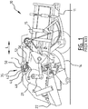
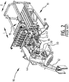
- balers In prior art balers a top fork-like part of the gearbox is connected via a pin to a coupling flange which is welded to a cross member extending in a transverse direction of the baler, and the cross member is welded to the frame of the baler. Such a prior art baler will be discussed in detail below with reference to FIG. 1 and FIG. 2 .
- the assembly of the cross member and gearbox involve a lot of machining and welding, resulting in an expensive construction. Misalignments in the transverse direction can be taken up by the parts during assembly.
- a square baler having a chassis, a plunger assembly and a plunger drive
- the chassis includes a baler frame with a baling chamber to receive crop material to be baled into square bales.
- the plunger assembly includes a reciprocating plunger head and a pair of connecting rods attached to the plunger head.
- the reciprocating plunger head is slidably mounted relative to the frame and is operable to reciprocate into and out of the chamber and apply a compressive force to the crop material.
- the connecting rods each include end housings, bearings mounted in each of the end housings, and an arm that interconnects the end housings.
- Each connecting rod is pivotally attached to a crank arm of the plunger drive at one end and to the plunger head at the other end.
- the connecting rods drivingly interconnect the crank arms and plunger head so that rotation of the crank arms causes reciprocating sliding movement of the plunger head.
- the crank arms and plunger assembly operate so that the crank arms are rotatable between the outermost location and the innermost location.
- US 6 457 405 discloses a baler comprising a frame, a pick-up assembly for picking up crop material from a field and a baling chamber for receiving crop material from the pick-up assembly.
- a plunger is mounted for reciprocating movement in the baling chamber for compression of the crop material therein.
- the plunger is driven by a gearbox which is affixed to the frame.
- a control unit adjusts the position of a movable wall portion in response to the signal from a load sensor, which is connected by a lever to the plunger gearbox for monitoring the reaction forces of the crop material on the plunger during the compression stroke.
- the lever arrangement includes a longitudinal pull member connected to one arm of the lever and a ball bearing mounted over the load sensor and connected to the other arm of the lever for precluding the effects of transverse or upward vibrations of the gearbox on the sensor.
- the object of the present invention is to provide a baler in which the forces exerted on the gearbox can be transferred by the cross member to the frame through a more cost efficient construction, whilst allowing to take up any misalignments in the transverse direction.
- a baler having a longitudinal direction extending in the traveling direction of the baler, and a transverse direction.
- the baler comprising a frame, a gearbox, and a cross member extending in the transverse direction and having a first end coupled to the frame and a second end coupled to the frame, wherein a top part of the gearbox is coupled to the cross member between said first end and said second end.
- the cross member is provided with a coupling flange extending perpendicular on the transverse direction, wherein the coupling flange is coupled with the top part of the gearbox, and wherein the coupling flange is clamped on the cross member in a weld-free manner.
- the baler of the second aspect has the advantage that the shape of the cross member can be more simple whilst the forces from the gearbox can be transferred efficiently to the frame.
- first and second ends of the cross member may either be mounted with mounting brackets as in the first aspect of the invention, or may be connected by other means to the frame, such as by bolts or by welding.
- the cross member has a cylindrical part between the first end and the second end, and the coupling flange has a cylindrical inner surface in contact with the cylindrical part of the cross member.
- the coupling flange is a single piece with an opening having dimensions corresponding with the dimensions of the cross section of the cross member such that the cross member can be arranged through said opening in order to clamp the coupling flange on the cross member.
- the coupling flange comprises two parts which are connected to each other around the cross member.
- Embodiments of the present invention can be used in agricultural balers for the production of rectangular bales of agricultural material such as hay, straw, silage or similar crop material that previously has been cut, windrowed or swathed, and is picked up from an agricultural field.
- the produced rectangular bales may have high density, hence a high mass, for example of 500 kg or more.
- Baler 10 has a longitudinal direction L extending in the traveling direction of the baler, and a transverse direction T.
- the baler 10 comprises a main frame 11 onto which all parts are mounted.
- the frame 11 of the baler 10 is typically a welded construction.
- the baler 10 comprises a baling chamber 15.
- a carrying member 30 carries a lower part of a gearbox 21 of the baler 10.
- the baling chamber 15 is positioned in line with the carrying member.
- the gearbox 21 provides actuation of the different parts of the baler 10 that need to be actuated.
- the gearbox 21 may be actuated by the tractor pulling the baler 10 by means of a transmission shaft 22 between the tractor and the baler 10, as illustrated in FIG. 1 .
- the gearbox 21 provides a direct actuation of the plunger 18.
- the plunger 18 may for example be connected to the gearbox 21 by means of crank arms 20 and pitman rods 19. The plunger 18 presses the collected crop material obtained from the feeder duct 14 against the bale being formed in the baling chamber 15.
- the plunger 18 moves on and against bottom plunger rails 41 which are provided for that purpose at both sides of the baling chamber 15, at right and left hand chamber walls.
- Top plunger rails 42 may optionally also be provided for forcing the movement of the plunger 18 onto the bottom plunger rails 41 and for restricting the movement of the plunger 18, thus preventing that the plunger 18 moves up and down.
- the gearbox 21 is affixed at its lower section to the carrying member 30.
- the top portion of the gearbox is held in place by a linkage and sensor assembly 35 connecting the top portion to a cross member 1.
- the linkage assembly 35 is designed to withstand the reaction forces of the plunger 18 on the body of the gearbox 21. It comprises a lever 40 which is mounted by a transverse cylindrical pin 42 to a flat protrusion 44 on the upper housing portion of the gearbox 21.
- the linkage assembly 35 further comprises a pull member 50 having a front end which is pivotally connected to the upper arm of the lever 40. The rear end of the pull member 50 is mounted between a pair of upright support plates 52 which are welded to the cross member 1 of the main frame 11.
- the support plates 52 have portions extending over and below cross member 1 and between which a transverse bracket plate 56 is welded. This plate 56 is facing the lower end of the lever 40.
- a bolt extends through a hole in the plate 56 and into the rear portion of a bearing block 60. At its front end the block 60 holds a spherical bearing which is mounted between the lower ends of the lever 40.
- a load sensor is inserted through holes in these lower ends and through the bearing. The load sensor is operable to sense the force exerted by the lever 40 on the bracket plate 56. Preferably, the sensor senses the force in a substantially longitudinal direction.
- FIG. 3A and FIG. 3B Now a cross member 110 with corresponding mounting brackets 120 according to a first embodiment of the invention will be illustrated referring to FIG. 3, FIG. 3A and FIG. 3B .
- the cross member 110 has a first end 111 and a second end 112.
- the first end 111 and the second end 112 are received in a first and second mounting bracket 120, such that the first end and the second end of the cross member is coupled to the frame in a weld-free way.
- the mounting brackets 120 can be welded or otherwise fixed to the frame 11 of the baler 10.
- a top part 40 of a gearbox 21 is coupled to the cross member 110 between the first end 111 and the second end 112.
- the first end 111 and the second end 112 comprise a part 113 having a circular cylindrical outer surface, wherein the axis of the cylindrical outer surface extends in the transverse direction of the baler.
- the radius R1, R2 may vary in the transverse direction, see FIG. 3B .
- Each mounting bracket 120 has an a cylindrical mounting surface 121, i.e. the inner surface of the bracket 120, which is adapted for receiving said first end and said second end, respectively.
- the part 113 has a vaulted outer surface seen in the transverse direction T of the baler, whilst the mounting bracket 120 has a straight cylindrical outer surface seen in the transverse direction T.
- the mounting bracket 120 has a near side 122 and a far side 123, said near side 122 being closer to the gearbox 21 than said far side 123.
- the part 113 is located at the near side 122 of the mounting bracket 120. In that way the part 113 is adapted for transferring forces F exerted by the gearbox 21 on the cross member 110 in the traveling direction of the baler, to the frame 11. Because of the vaulted form of the part 113, the forces can be well transferred, also when the cross member is subject to bending forces.
- the cross member 110 has a substantially H shaped cross section, wherein the first and second end parts of the cross member each comprise the part 113, a second flange part 114 and a middle part 115.
- the middle part 115 connects the first flange part 113 with the second flange part 114.
- the cross member 110 is provided with a coupling flange 116 extending in the longitudinal direction L of the baler 10 between the first end 111 and the second end 112, typically centrally between the first end 111 and the second end 112.
- the cross member 110 and the coupling flange 116 are made as a single piece, e.g. a cast piece.
- the coupling flange 116 is meant to be coupled with a top fork part 44 of the gearbox 21.
- the flange 116 is meant to fit between the fork legs of top part 44, and a pen 42 extends through the fork part 44 and through a ball 117 in a through-opening 119 of the flange 116, such that the ball 117 and through-opening 119 form a ball joint.
- the ball 117 can be placed in the through-opening 119 in a rotated position (with the through-opening therein extending in the longitudinal direction L), whereupon the ball 117 can be rotated into position with the through-opening therein extending in the transverse direction T.
- the pen 42 extends through the through-opening of the ball 117. In that manner the forces on the gear box 21 can be transferred to the cross member 110 whilst limiting high localized stresses in the cross member.
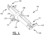
- FIG. 4 illustrates a second embodiment of a cross member 110 with corresponding mounting brackets 120.
- the cross member 110 has a first end 111 and a second end 112.
- the first end 111 and the second end 112 are received in a mounting bracket 120, such that the first end 111 and the second end 112 of the cross member is coupled to the frame in a weld-free way.
- the connection is free from shear and friction force transferring bolts which extend vertically through the cross member.
- a pushing member such as a push bolt 140
- a pull member such as a pull bolt (not shown), for maintaining in position the first and second ends 111, 112.
- a coupling flange 216 for coupling the cross member 110 to a gearbox is clamped on the cross member 110 in a weld-free manner.
- the cross member 110 has a cylindrical part 118 in the middle between the first end 111 and the second end 112, and the coupling flange 216 has a cylindrical inner surface 218 in contact with the cylindrical part 118 of the cross member 110.
- the coupling flange 216 is a piece with a cylindrical through-hole having a diameter corresponding with the diameter of the cylindrical middle part 118 of the cross member, such that the cross member 110 can be arranged through the through-hole in order to clamp the coupling flange 216 on the cross member 110.
- the stress in the cross member 110 caused by the forces exerted by the gearbox on the cross member 110 will be more focused around the coupling flange 216.
- Both the first and second embodiment give results which are significantly improved compared to prior art embodiments where the cross member is welded to the frame.
- the coupling flange 216 is coupled with a top fork part 44 of the gearbox 21, see FIG. 5 . More in particular, the flange 216 fits between the fork legs of top part 44, and a pen 42 extends through the fork part 44 and through a ball 217 in a through-opening 219 of the flange 216, such that the ball 217 and through-opening 219 form a ball joint.
- the ball 217 can be placed in the through-opening 219 in a rotated position (with the through-opening therein extending in the longitudinal direction L), whereupon the ball 217 can be rotated into position with the through-opening therein extending in the transverse direction T.
- the pen 42 extends through the through-opening of the ball 217. This will allow the forces on the gear box 21 to be transferred to the cross member 110 in an improved manner.
- FIG. 5 illustrates the cross member 110 arranged in a baler 10 via the mounting brackets 120 of the first embodiment.
- the mounting brackets 120 may be welded to the respective sidewalls of the baler.
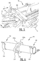
- FIG. 6 illustrates a third embodiment of a cross member 110 with mounting brackets 120.
- the cross member 110 has a first end 111 and a second end 112.
- the first end 111 and the second end 112 are received in the mounting brackets 120, such that the first end and the second end of the cross member is coupled to the frame in a weld-free way.
- a coupling flange 316a, 316b for coupling the cross member 110 to a gearbox is clamped on the cross member 110 in a weld-free manner.
- the cross member 110 has a circular cylindrical shape over the entire length between the first end 111 and the second end 112.
- the coupling flange is formed by two parts 316a, 316b which are connected to each other in order to be clamped around the cross member 110. When the two parts 316a, 316b are clamped against each other, they define a cylindrical inner surface which is in contact with the cylindrical outer surface of the cross member 110.
- the coupling flange 316 is meant to be coupled with a top fork part 44 of the gearbox 21. More in particular, the flange 316 is meant to fit between the fork legs of top part 44, and a pen 42 extends through the fork part 44 and through a ball 317 in a through-opening 319 of the flange 316, such that the ball 317 and through-opening 319 form a ball joint. The pen 42 extends through the through-opening of the ball 317.
Landscapes
- Life Sciences & Earth Sciences (AREA)
- Environmental Sciences (AREA)
- Engineering & Computer Science (AREA)
- Mechanical Engineering (AREA)
- Agricultural Machines (AREA)
- Body Structure For Vehicles (AREA)
- Harvester Elements (AREA)
Abstract
Description
- The present invention relates to balers comprising a frame, a gearbox, and a cross member extending in the transverse direction for coupling a top part of the gearbox to the frame. More in particular the invention relates to rectangular balers provided with a heavy gearbox.
- In prior art balers a top fork-like part of the gearbox is connected via a pin to a coupling flange which is welded to a cross member extending in a transverse direction of the baler, and the cross member is welded to the frame of the baler. Such a prior art baler will be discussed in detail below with reference to
FIG. 1 andFIG. 2 . - In such an embodiment the assembly of the cross member and gearbox involve a lot of machining and welding, resulting in an expensive construction. Misalignments in the transverse direction can be taken up by the parts during assembly.
- Such an embodiment is shown in
US 2014/158002 in which a square baler having a chassis, a plunger assembly and a plunger drive is disclosed. The chassis includes a baler frame with a baling chamber to receive crop material to be baled into square bales. The plunger assembly includes a reciprocating plunger head and a pair of connecting rods attached to the plunger head. The reciprocating plunger head is slidably mounted relative to the frame and is operable to reciprocate into and out of the chamber and apply a compressive force to the crop material. The connecting rods each include end housings, bearings mounted in each of the end housings, and an arm that interconnects the end housings. Each connecting rod is pivotally attached to a crank arm of the plunger drive at one end and to the plunger head at the other end.
The connecting rods drivingly interconnect the crank arms and plunger head so that rotation of the crank arms causes reciprocating sliding movement of the plunger head. The crank arms and plunger assembly operate so that the crank arms are rotatable between the outermost location and the innermost location. - Also
US 6 457 405 discloses a baler comprising a frame, a pick-up assembly for picking up crop material from a field and a baling chamber for receiving crop material from the pick-up assembly. A plunger is mounted for reciprocating movement in the baling chamber for compression of the crop material therein. The plunger is driven by a gearbox which is affixed to the frame. A control unit adjusts the position of a movable wall portion in response to the signal from a load sensor, which is connected by a lever to the plunger gearbox for monitoring the reaction forces of the crop material on the plunger during the compression stroke. The lever arrangement includes a longitudinal pull member connected to one arm of the lever and a ball bearing mounted over the load sensor and connected to the other arm of the lever for precluding the effects of transverse or upward vibrations of the gearbox on the sensor. - In such prior art embodiments heavy loads on the gearbox are not dealt with in an optimal way, and may result in high local stresses in the cross member.
- The object of the present invention is to provide a baler in which the forces exerted on the gearbox can be transferred by the cross member to the frame through a more cost efficient construction, whilst allowing to take up any misalignments in the transverse direction.
- According to an aspect of the invention, there is provided a baler having a longitudinal direction extending in the traveling direction of the baler, and a transverse direction. The baler comprising a frame, a gearbox, and a cross member extending in the transverse direction and having a first end coupled to the frame and a second end coupled to the frame, wherein a top part of the gearbox is coupled to the cross member between said first end and said second end. The cross member is provided with a coupling flange extending perpendicular on the transverse direction, wherein the coupling flange is coupled with the top part of the gearbox, and wherein the coupling flange is clamped on the cross member in a weld-free manner.
- The baler of the second aspect has the advantage that the shape of the cross member can be more simple whilst the forces from the gearbox can be transferred efficiently to the frame.
- According to the second aspect the first and second ends of the cross member may either be mounted with mounting brackets as in the first aspect of the invention, or may be connected by other means to the frame, such as by bolts or by welding.
- In a preferred embodiment the cross member has a cylindrical part between the first end and the second end, and the coupling flange has a cylindrical inner surface in contact with the cylindrical part of the cross member.
- In an exemplary embodiment the coupling flange is a single piece with an opening having dimensions corresponding with the dimensions of the cross section of the cross member such that the cross member can be arranged through said opening in order to clamp the coupling flange on the cross member. In another exemplary embodiment the coupling flange comprises two parts which are connected to each other around the cross member.
- The advantages of this invention will be apparent upon consideration of the following detailed disclosure of exemplary non-limiting embodiments of the invention, especially when taken in conjunction with the accompanying drawings wherein:
-
FIG. 1 is a schematic side view of a prior art rectangular baler; -
FIG. 2 is a schematic perspective view of a prior art rectangular baler; -
FIG. 3 is a schematic perspective view of a first embodiment of a cross member with mounting brackets of the invention; -
FIG. 3A is a cross section along line A-A across an end part of the cross member with mounting brackets offigure 3 ; -
FIG. 3B is a partial section along line B-B of the cross member with mounting brackets offigure 3 ; -
FIG. 4 is a schematic perspective view of a second embodiment of a cross member with mounting brackets of the invention; -
FIG. 5 is a perspective view of a part of an embodiment of a baler of the invention; and -
FIG. 6 is a schematic perspective view of a third embodiment of a cross member with mounting brackets of the invention. - The drawings are only schematic and are non-limiting. In the drawings, the size of some of the elements may be exaggerated and not drawn on scale for illustrative purposes.
- Any reference signs in the claims shall not be construed as limiting the scope. In the drawings, the same reference signs refer to the same or analogous elements.
- The terms "front", "rear", "forward", "rearward", "left" and "right" used throughout this description are determined with respect to the normal direction of travel of the machine in operation. However, they are not to be construed as limiting terms.
- Embodiments of the present invention can be used in agricultural balers for the production of rectangular bales of agricultural material such as hay, straw, silage or similar crop material that previously has been cut, windrowed or swathed, and is picked up from an agricultural field. The produced rectangular bales may have high density, hence a high mass, for example of 500 kg or more.
- Part of an
agricultural baler 10 of the prior art is illustrated inFIG. 1 andFIG. 2 .Baler 10 has a longitudinal direction L extending in the traveling direction of the baler, and a transverse direction T. Thebaler 10 comprises amain frame 11 onto which all parts are mounted. Theframe 11 of thebaler 10 is typically a welded construction. - The
baler 10 comprises a balingchamber 15. A carryingmember 30 carries a lower part of agearbox 21 of thebaler 10. Typically, the balingchamber 15 is positioned in line with the carrying member. Thegearbox 21 provides actuation of the different parts of thebaler 10 that need to be actuated. Thegearbox 21 may be actuated by the tractor pulling thebaler 10 by means of atransmission shaft 22 between the tractor and thebaler 10, as illustrated inFIG. 1 . Thegearbox 21 provides a direct actuation of theplunger 18. Hereto, theplunger 18 may for example be connected to thegearbox 21 by means of crankarms 20 andpitman rods 19. Theplunger 18 presses the collected crop material obtained from thefeeder duct 14 against the bale being formed in thebaling chamber 15. Theplunger 18 moves on and against bottom plunger rails 41 which are provided for that purpose at both sides of the balingchamber 15, at right and left hand chamber walls. Top plunger rails 42 may optionally also be provided for forcing the movement of theplunger 18 onto the bottom plunger rails 41 and for restricting the movement of theplunger 18, thus preventing that theplunger 18 moves up and down. - The
gearbox 21 is affixed at its lower section to the carryingmember 30. The top portion of the gearbox is held in place by a linkage andsensor assembly 35 connecting the top portion to a cross member 1. Thelinkage assembly 35 is designed to withstand the reaction forces of theplunger 18 on the body of thegearbox 21. It comprises alever 40 which is mounted by a transversecylindrical pin 42 to aflat protrusion 44 on the upper housing portion of thegearbox 21. Thelinkage assembly 35 further comprises apull member 50 having a front end which is pivotally connected to the upper arm of thelever 40. The rear end of thepull member 50 is mounted between a pair ofupright support plates 52 which are welded to the cross member 1 of themain frame 11. Thesupport plates 52 have portions extending over and below cross member 1 and between which atransverse bracket plate 56 is welded. Thisplate 56 is facing the lower end of thelever 40. A bolt extends through a hole in theplate 56 and into the rear portion of a bearing block 60. At its front end the block 60 holds a spherical bearing which is mounted between the lower ends of thelever 40. A load sensor is inserted through holes in these lower ends and through the bearing. The load sensor is operable to sense the force exerted by thelever 40 on thebracket plate 56. Preferably, the sensor senses the force in a substantially longitudinal direction. - During each compression stroke of the
plunger 18, the reaction forces of the crop material upon theplunger 18 are transmitted by thepitman rod 19 and thecrank arm 20 upon thegearbox 21. Part of these forces is assumed by the attachment of the lower part of thegearbox 21 to themain frame 11. The remainder of the reaction forces is assumed by thelinkage assembly 35 at the top part of thegearbox 21. - Now a
cross member 110 with corresponding mountingbrackets 120 according to a first embodiment of the invention will be illustrated referring toFIG. 3, FIG. 3A and FIG. 3B . - The
cross member 110 has afirst end 111 and asecond end 112. Thefirst end 111 and thesecond end 112 are received in a first and second mountingbracket 120, such that the first end and the second end of the cross member is coupled to the frame in a weld-free way. The mountingbrackets 120 can be welded or otherwise fixed to theframe 11 of thebaler 10. Atop part 40 of agearbox 21 is coupled to thecross member 110 between thefirst end 111 and thesecond end 112. - The
first end 111 and thesecond end 112 comprise apart 113 having a circular cylindrical outer surface, wherein the axis of the cylindrical outer surface extends in the transverse direction of the baler. The radius R1, R2 may vary in the transverse direction, seeFIG. 3B . Each mountingbracket 120 has an acylindrical mounting surface 121, i.e. the inner surface of thebracket 120, which is adapted for receiving said first end and said second end, respectively. - Preferably, the
part 113 has a vaulted outer surface seen in the transverse direction T of the baler, whilst the mountingbracket 120 has a straight cylindrical outer surface seen in the transverse direction T. The mountingbracket 120 has anear side 122 and afar side 123, said nearside 122 being closer to thegearbox 21 than saidfar side 123. Thepart 113 is located at thenear side 122 of the mountingbracket 120. In that way thepart 113 is adapted for transferring forces F exerted by thegearbox 21 on thecross member 110 in the traveling direction of the baler, to theframe 11. Because of the vaulted form of thepart 113, the forces can be well transferred, also when the cross member is subject to bending forces. - The
cross member 110 has a substantially H shaped cross section, wherein the first and second end parts of the cross member each comprise thepart 113, asecond flange part 114 and amiddle part 115. Themiddle part 115 connects thefirst flange part 113 with thesecond flange part 114. - The
cross member 110 is provided with acoupling flange 116 extending in the longitudinal direction L of thebaler 10 between thefirst end 111 and thesecond end 112, typically centrally between thefirst end 111 and thesecond end 112. In the first embodiment thecross member 110 and thecoupling flange 116 are made as a single piece, e.g. a cast piece. Thecoupling flange 116 is meant to be coupled with atop fork part 44 of thegearbox 21. More in particular, theflange 116 is meant to fit between the fork legs oftop part 44, and apen 42 extends through thefork part 44 and through aball 117 in a through-opening 119 of theflange 116, such that theball 117 and through-opening 119 form a ball joint. Theball 117 can be placed in the through-opening 119 in a rotated position (with the through-opening therein extending in the longitudinal direction L), whereupon theball 117 can be rotated into position with the through-opening therein extending in the transverse direction T. Thepen 42 extends through the through-opening of theball 117. In that manner the forces on thegear box 21 can be transferred to thecross member 110 whilst limiting high localized stresses in the cross member. -
FIG. 4 illustrates a second embodiment of across member 110 with corresponding mountingbrackets 120. Thecross member 110 has afirst end 111 and asecond end 112. Thefirst end 111 and thesecond end 112 are received in a mountingbracket 120, such that thefirst end 111 and thesecond end 112 of the cross member is coupled to the frame in a weld-free way. Also, the connection is free from shear and friction force transferring bolts which extend vertically through the cross member. However, there may be provided a pushing member, such as apush bolt 140, which keeps thecross member 110 in place with its first and second ends 111, 112 received in first and second mountingbrackets 120. Alternatively, there may be provided a pull member, such as a pull bolt (not shown), for maintaining in position the first and second ends 111, 112. - In the second embodiment a
coupling flange 216 for coupling thecross member 110 to a gearbox is clamped on thecross member 110 in a weld-free manner. To that end thecross member 110 has acylindrical part 118 in the middle between thefirst end 111 and thesecond end 112, and thecoupling flange 216 has a cylindricalinner surface 218 in contact with thecylindrical part 118 of thecross member 110. - In the second embodiment the
coupling flange 216 is a piece with a cylindrical through-hole having a diameter corresponding with the diameter of the cylindricalmiddle part 118 of the cross member, such that thecross member 110 can be arranged through the through-hole in order to clamp thecoupling flange 216 on thecross member 110. Compared to the first embodiment the stress in thecross member 110 caused by the forces exerted by the gearbox on thecross member 110 will be more focused around thecoupling flange 216. Both the first and second embodiment give results which are significantly improved compared to prior art embodiments where the cross member is welded to the frame. - The
coupling flange 216 is coupled with atop fork part 44 of thegearbox 21, seeFIG. 5 . More in particular, theflange 216 fits between the fork legs oftop part 44, and apen 42 extends through thefork part 44 and through aball 217 in a through-opening 219 of theflange 216, such that theball 217 and through-opening 219 form a ball joint. Theball 217 can be placed in the through-opening 219 in a rotated position (with the through-opening therein extending in the longitudinal direction L), whereupon theball 217 can be rotated into position with the through-opening therein extending in the transverse direction T. Thepen 42 extends through the through-opening of theball 217. This will allow the forces on thegear box 21 to be transferred to thecross member 110 in an improved manner. -
FIG. 5 illustrates thecross member 110 arranged in abaler 10 via the mountingbrackets 120 of the first embodiment. The mountingbrackets 120 may be welded to the respective sidewalls of the baler. -
FIG. 6 illustrates a third embodiment of across member 110 with mountingbrackets 120. Thecross member 110 has afirst end 111 and asecond end 112. Thefirst end 111 and thesecond end 112 are received in the mountingbrackets 120, such that the first end and the second end of the cross member is coupled to the frame in a weld-free way. In the third embodiment acoupling flange cross member 110 to a gearbox, is clamped on thecross member 110 in a weld-free manner. - The
cross member 110 has a circular cylindrical shape over the entire length between thefirst end 111 and thesecond end 112. The coupling flange is formed by twoparts cross member 110. When the twoparts cross member 110. - The coupling flange 316 is meant to be coupled with a
top fork part 44 of thegearbox 21. More in particular, the flange 316 is meant to fit between the fork legs oftop part 44, and apen 42 extends through thefork part 44 and through aball 317 in a through-opening 319 of the flange 316, such that theball 317 and through-opening 319 form a ball joint. Thepen 42 extends through the through-opening of theball 317. - While the principles of the invention have been set out above in connection with specific embodiments, it is to be understood that this description is merely made by way of example and not as a limitation of the scope of protection, which is determined by the appended claims.
Claims (6)
- Baler having a longitudinal direction extending in the traveling direction of the baler, and a transverse direction, the baler comprising a frame, a gearbox (21), and a cross member (110) extending in the transverse direction for coupling a top part (44) of the gearbox (21) to the frame (11) and having a first end (111) coupled to the frame (11) and a second end (112) coupled to the frame (11), wherein said top part (44) of the gearbox (21) is coupled to the cross member (110) between said first end (111) and said second end (112); the cross member (110) is provided with a coupling flange (216; 316a,316b) extending perpendicular on the transverse direction, wherein said coupling flange is coupled with the top part (44) of the gearbox (21);
characterized in that the coupling flange (216; 316a,316b) is clamped around the cross member (110) in a weld-free manner. - Baler of claim 1, wherein the cross member (110) has a cylindrical part between the first end (111) and the second end (112), and the coupling flange (216; 316a,316b) has a cylindrical inner surface in contact with the cylindrical part of the cross member (110).
- Baler of claim 1 or 2, wherein the coupling flange (216) is a single piece with an opening having dimensions corresponding with the dimensions of the cross section of the cross member (110), such that the cross member (110) can be arranged through said opening in order to clamp the coupling flange on the cross member (110).
- Baler of claim 1 or 2, wherein the coupling flange (316a,316b) comprises two parts which are connected to each other around the cross member (110).
- Baler of any one of the claims 1-4, wherein the coupling flange (216; 316a,316b) is provided with a through-opening (217; 317) extending in the transverse direction (T), and wherein a pen (42) extends through the through-opening (217; 317) connecting the top part (44) of the gearbox (21) with the cross member (110).
- Baler of claim 5, wherein a ball (217; 317) having a through-opening is inserted in said through-opening (219; 319) of the coupling flange, and said pen (42) extends through the through-opening of the ball.
Applications Claiming Priority (3)
| Application Number | Priority Date | Filing Date | Title |
|---|---|---|---|
| BE2014/0592A BE1022407B1 (en) | 2014-07-30 | 2014-07-30 | BALL PRESS WITH IMPROVED CROSS BEAR FOR MOUNTING THE GEARBOX |
| PCT/EP2015/066909 WO2016016095A1 (en) | 2014-07-30 | 2015-07-23 | Baler with improved cross member for mounting the gearbox |
| EP15742009.2A EP3190868B1 (en) | 2014-07-30 | 2015-07-23 | Baler with improved cross member for mounting the gearbox |
Related Parent Applications (2)
| Application Number | Title | Priority Date | Filing Date |
|---|---|---|---|
| EP15742009.2A Division EP3190868B1 (en) | 2014-07-30 | 2015-07-23 | Baler with improved cross member for mounting the gearbox |
| EP15742009.2A Division-Into EP3190868B1 (en) | 2014-07-30 | 2015-07-23 | Baler with improved cross member for mounting the gearbox |
Publications (2)
| Publication Number | Publication Date |
|---|---|
| EP3235367A1 true EP3235367A1 (en) | 2017-10-25 |
| EP3235367B1 EP3235367B1 (en) | 2020-01-29 |
Family
ID=51609871
Family Applications (2)
| Application Number | Title | Priority Date | Filing Date |
|---|---|---|---|
| EP15742009.2A Not-in-force EP3190868B1 (en) | 2014-07-30 | 2015-07-23 | Baler with improved cross member for mounting the gearbox |
| EP17157827.1A Active EP3235367B1 (en) | 2014-07-30 | 2015-07-23 | Baler with improved cross member for mounting the gearbox |
Family Applications Before (1)
| Application Number | Title | Priority Date | Filing Date |
|---|---|---|---|
| EP15742009.2A Not-in-force EP3190868B1 (en) | 2014-07-30 | 2015-07-23 | Baler with improved cross member for mounting the gearbox |
Country Status (4)
| Country | Link |
|---|---|
| US (1) | US10201129B2 (en) |
| EP (2) | EP3190868B1 (en) |
| BE (1) | BE1022407B1 (en) |
| WO (1) | WO2016016095A1 (en) |
Families Citing this family (2)
| Publication number | Priority date | Publication date | Assignee | Title |
|---|---|---|---|---|
| BE1022406B1 (en) * | 2014-07-30 | 2016-03-24 | Cnh Industrial Belgium Nv | RECTANGULAR BALER PRESS WITH IMPROVED TRANSFER OF FORCES TO THE CHASSIS |
| EP3646710B1 (en) * | 2018-11-02 | 2021-06-30 | CNH Industrial Belgium NV | A mounting for a baling machine gearbox |
Citations (4)
| Publication number | Priority date | Publication date | Assignee | Title |
|---|---|---|---|---|
| US5123338A (en) * | 1989-03-03 | 1992-06-23 | Hesston Braud | Apparatus for regulating the density of fodder bales |
| EP1060652A1 (en) * | 1999-06-12 | 2000-12-20 | Case Harvesting Systems GmbH | Drive for a plunger press for agricultural produce |
| US6457405B1 (en) | 1999-07-08 | 2002-10-01 | New Holland North America, Inc. | Sensor arrangement for an agricultural baler |
| US20140158002A1 (en) | 2012-12-11 | 2014-06-12 | Agco Corporation | Square baler having planetary plunger drive |
Family Cites Families (20)
| Publication number | Priority date | Publication date | Assignee | Title |
|---|---|---|---|---|
| US4062172A (en) * | 1976-02-09 | 1977-12-13 | Sperry Rand Corporation | Raising and lowering mechanism for the rear chamber in a crop material roll forming machine |
| US4525991A (en) * | 1984-01-09 | 1985-07-02 | Sperry Corporation | Baler feeder mechanism |
| US4503762A (en) * | 1984-04-12 | 1985-03-12 | Sperry Corporation | Knotter trip mechanism |
| DE3820367A1 (en) | 1988-06-15 | 1989-12-21 | Claas Ohg | CONTROL DEVICE OF A STRAW BALE PRESS |
| DE4140483C2 (en) | 1991-12-09 | 1994-03-10 | Claas Ohg | Straw baler with load tester |
| US5488883A (en) * | 1992-12-18 | 1996-02-06 | Vermeer Manufacturing Company | Direct drive system for a baler |
| US5661961A (en) * | 1995-09-01 | 1997-09-02 | Westhoff; Gerald F. | Crop processor for round hay balers |
| DE19628604A1 (en) | 1996-07-16 | 1998-01-22 | Claas Usines France | Drive system for agricultural big balers |
| GB9702791D0 (en) | 1997-02-11 | 1997-04-02 | Ford New Holland Nv | Bale density control system for agricultural balers |
| GB2330110A (en) | 1997-10-07 | 1999-04-14 | Ford New Holland Nv | Bale density control system for agricultural balers |
| DE19748748C2 (en) | 1997-11-05 | 2000-06-15 | Lely Welger Maschinenfabrik Gm | Channel baling press with a control device |
| DE19818127C1 (en) | 1998-04-23 | 1999-11-18 | Welger Geb | Channel baling press |
| US6050052A (en) * | 1998-06-17 | 2000-04-18 | Hay & Forage Industries | Round baler having positive start wrapper dispensing mechanism |
| GB2351940A (en) | 1999-07-08 | 2001-01-17 | Ford New Holland Nv | Baler capacity display and method |
| US6247291B1 (en) * | 1999-07-21 | 2001-06-19 | New Holland North America, Inc. | Storage apparatus for round baler wrapping material |
| US6272825B1 (en) * | 1999-09-15 | 2001-08-14 | Hay & Forage Industries | Round baler having hydraulically sequenced clutch and tailgate cylinders |
| US6543342B2 (en) | 2000-06-29 | 2003-04-08 | New Holland North America, Inc. | Method for determining a value relating to compressing rate of a baler |
| BE1019181A3 (en) | 2010-02-12 | 2012-04-03 | Cnh Belgium Nv | SQUARE BALL PRESS AND ACCOMPANYING CONTROL METHOD. |
| BE1019886A3 (en) | 2011-03-22 | 2013-02-05 | Cnh Belgium Nv | ALIGNMENT OF PLUNGER WITH GEARBOX IN A BALL PRESS. |
| BE1023781B1 (en) * | 2016-05-18 | 2017-07-24 | Cnh Industrial Belgium Nv | RECTANGULAR BALL PRESS WITH AN IMPROVED SYSTEM AND AN IMPROVED CONTROL METHOD FOR CONTROLLING THE BALE FORM |
-
2014
- 2014-07-30 BE BE2014/0592A patent/BE1022407B1/en not_active IP Right Cessation
-
2015
- 2015-07-23 US US15/500,395 patent/US10201129B2/en active Active
- 2015-07-23 EP EP15742009.2A patent/EP3190868B1/en not_active Not-in-force
- 2015-07-23 WO PCT/EP2015/066909 patent/WO2016016095A1/en not_active Ceased
- 2015-07-23 EP EP17157827.1A patent/EP3235367B1/en active Active
Patent Citations (4)
| Publication number | Priority date | Publication date | Assignee | Title |
|---|---|---|---|---|
| US5123338A (en) * | 1989-03-03 | 1992-06-23 | Hesston Braud | Apparatus for regulating the density of fodder bales |
| EP1060652A1 (en) * | 1999-06-12 | 2000-12-20 | Case Harvesting Systems GmbH | Drive for a plunger press for agricultural produce |
| US6457405B1 (en) | 1999-07-08 | 2002-10-01 | New Holland North America, Inc. | Sensor arrangement for an agricultural baler |
| US20140158002A1 (en) | 2012-12-11 | 2014-06-12 | Agco Corporation | Square baler having planetary plunger drive |
Also Published As
| Publication number | Publication date |
|---|---|
| EP3190868A1 (en) | 2017-07-19 |
| US10201129B2 (en) | 2019-02-12 |
| EP3190868B1 (en) | 2019-01-02 |
| US20170215343A1 (en) | 2017-08-03 |
| BE1022407B1 (en) | 2016-03-24 |
| WO2016016095A1 (en) | 2016-02-04 |
| EP3235367B1 (en) | 2020-01-29 |
Similar Documents
| Publication | Publication Date | Title |
|---|---|---|
| EP3053430B1 (en) | Baler | |
| EP3245862B1 (en) | Rectangular baler with improved baling control system and control method | |
| EP3235367B1 (en) | Baler with improved cross member for mounting the gearbox | |
| CN109548498B (en) | Square baler with side walls that can be set into oscillation | |
| EP3809818B1 (en) | Axle arrangement for an agricultural baler | |
| EP1066748A1 (en) | Sensor arrangement for an agricultural baler | |
| US12041884B2 (en) | Agricultural baling machines | |
| EP2725891B1 (en) | Agricultural baler with bale chute | |
| US20210243959A1 (en) | Agricultural baling machines | |
| EP3473080B1 (en) | Baler plunger guide system | |
| EP3231275B1 (en) | Rectangular baler with improved stuffer mechanism | |
| US11793116B2 (en) | Agricultural baler with frameless and weldless plunger | |
| EP4111848B1 (en) | Stuffer assembly for an agricultural baler | |
| EP3190867B1 (en) | Rectangular baler with improved transmission of forces to the chassis | |
| EP3809817B1 (en) | Agricultural baler with an axle arrangement | |
| US12120986B2 (en) | Agricultural baling machines | |
| US4063405A (en) | Shock-isolated electric actuator for moving a harvesting machine header | |
| EP4466978A1 (en) | Panel compression system for baler implement | |
| EP4445719A1 (en) | Panel compression system for baler implement | |
| HU191273B (en) | Baling apparats | |
| JPS5843715A (en) | Horizontal type baler |
Legal Events
| Date | Code | Title | Description |
|---|---|---|---|
| PUAI | Public reference made under article 153(3) epc to a published international application that has entered the european phase |
Free format text: ORIGINAL CODE: 0009012 |
|
| STAA | Information on the status of an ep patent application or granted ep patent |
Free format text: STATUS: THE APPLICATION HAS BEEN PUBLISHED |
|
| AC | Divisional application: reference to earlier application |
Ref document number: 3190868 Country of ref document: EP Kind code of ref document: P |
|
| AK | Designated contracting states |
Kind code of ref document: A1 Designated state(s): AL AT BE BG CH CY CZ DE DK EE ES FI FR GB GR HR HU IE IS IT LI LT LU LV MC MK MT NL NO PL PT RO RS SE SI SK SM TR |
|
| AX | Request for extension of the european patent |
Extension state: BA ME |
|
| STAA | Information on the status of an ep patent application or granted ep patent |
Free format text: STATUS: REQUEST FOR EXAMINATION WAS MADE |
|
| 17P | Request for examination filed |
Effective date: 20180425 |
|
| RBV | Designated contracting states (corrected) |
Designated state(s): AL AT BE BG CH CY CZ DE DK EE ES FI FR GB GR HR HU IE IS IT LI LT LU LV MC MK MT NL NO PL PT RO RS SE SI SK SM TR |
|
| GRAP | Despatch of communication of intention to grant a patent |
Free format text: ORIGINAL CODE: EPIDOSNIGR1 |
|
| STAA | Information on the status of an ep patent application or granted ep patent |
Free format text: STATUS: GRANT OF PATENT IS INTENDED |
|
| INTG | Intention to grant announced |
Effective date: 20190320 |
|
| GRAJ | Information related to disapproval of communication of intention to grant by the applicant or resumption of examination proceedings by the epo deleted |
Free format text: ORIGINAL CODE: EPIDOSDIGR1 |
|
| STAA | Information on the status of an ep patent application or granted ep patent |
Free format text: STATUS: REQUEST FOR EXAMINATION WAS MADE |
|
| INTC | Intention to grant announced (deleted) | ||
| GRAP | Despatch of communication of intention to grant a patent |
Free format text: ORIGINAL CODE: EPIDOSNIGR1 |
|
| STAA | Information on the status of an ep patent application or granted ep patent |
Free format text: STATUS: GRANT OF PATENT IS INTENDED |
|
| INTG | Intention to grant announced |
Effective date: 20190904 |
|
| GRAS | Grant fee paid |
Free format text: ORIGINAL CODE: EPIDOSNIGR3 |
|
| GRAA | (expected) grant |
Free format text: ORIGINAL CODE: 0009210 |
|
| STAA | Information on the status of an ep patent application or granted ep patent |
Free format text: STATUS: THE PATENT HAS BEEN GRANTED |
|
| AC | Divisional application: reference to earlier application |
Ref document number: 3190868 Country of ref document: EP Kind code of ref document: P |
|
| AK | Designated contracting states |
Kind code of ref document: B1 Designated state(s): AL AT BE BG CH CY CZ DE DK EE ES FI FR GB GR HR HU IE IS IT LI LT LU LV MC MK MT NL NO PL PT RO RS SE SI SK SM TR |
|
| REG | Reference to a national code |
Ref country code: GB Ref legal event code: FG4D |
|
| REG | Reference to a national code |
Ref country code: CH Ref legal event code: EP |
|
| REG | Reference to a national code |
Ref country code: AT Ref legal event code: REF Ref document number: 1227820 Country of ref document: AT Kind code of ref document: T Effective date: 20200215 |
|
| REG | Reference to a national code |
Ref country code: IE Ref legal event code: FG4D |
|
| REG | Reference to a national code |
Ref country code: DE Ref legal event code: R096 Ref document number: 602015046333 Country of ref document: DE |
|
| REG | Reference to a national code |
Ref country code: NL Ref legal event code: MP Effective date: 20200129 |
|
| PG25 | Lapsed in a contracting state [announced via postgrant information from national office to epo] |
Ref country code: FI Free format text: LAPSE BECAUSE OF FAILURE TO SUBMIT A TRANSLATION OF THE DESCRIPTION OR TO PAY THE FEE WITHIN THE PRESCRIBED TIME-LIMIT Effective date: 20200129 Ref country code: PT Free format text: LAPSE BECAUSE OF FAILURE TO SUBMIT A TRANSLATION OF THE DESCRIPTION OR TO PAY THE FEE WITHIN THE PRESCRIBED TIME-LIMIT Effective date: 20200621 Ref country code: NO Free format text: LAPSE BECAUSE OF FAILURE TO SUBMIT A TRANSLATION OF THE DESCRIPTION OR TO PAY THE FEE WITHIN THE PRESCRIBED TIME-LIMIT Effective date: 20200429 Ref country code: RS Free format text: LAPSE BECAUSE OF FAILURE TO SUBMIT A TRANSLATION OF THE DESCRIPTION OR TO PAY THE FEE WITHIN THE PRESCRIBED TIME-LIMIT Effective date: 20200129 |
|
| REG | Reference to a national code |
Ref country code: LT Ref legal event code: MG4D |
|
| PG25 | Lapsed in a contracting state [announced via postgrant information from national office to epo] |
Ref country code: BG Free format text: LAPSE BECAUSE OF FAILURE TO SUBMIT A TRANSLATION OF THE DESCRIPTION OR TO PAY THE FEE WITHIN THE PRESCRIBED TIME-LIMIT Effective date: 20200429 Ref country code: HR Free format text: LAPSE BECAUSE OF FAILURE TO SUBMIT A TRANSLATION OF THE DESCRIPTION OR TO PAY THE FEE WITHIN THE PRESCRIBED TIME-LIMIT Effective date: 20200129 Ref country code: IS Free format text: LAPSE BECAUSE OF FAILURE TO SUBMIT A TRANSLATION OF THE DESCRIPTION OR TO PAY THE FEE WITHIN THE PRESCRIBED TIME-LIMIT Effective date: 20200529 Ref country code: SE Free format text: LAPSE BECAUSE OF FAILURE TO SUBMIT A TRANSLATION OF THE DESCRIPTION OR TO PAY THE FEE WITHIN THE PRESCRIBED TIME-LIMIT Effective date: 20200129 Ref country code: LV Free format text: LAPSE BECAUSE OF FAILURE TO SUBMIT A TRANSLATION OF THE DESCRIPTION OR TO PAY THE FEE WITHIN THE PRESCRIBED TIME-LIMIT Effective date: 20200129 Ref country code: GR Free format text: LAPSE BECAUSE OF FAILURE TO SUBMIT A TRANSLATION OF THE DESCRIPTION OR TO PAY THE FEE WITHIN THE PRESCRIBED TIME-LIMIT Effective date: 20200430 |
|
| PG25 | Lapsed in a contracting state [announced via postgrant information from national office to epo] |
Ref country code: NL Free format text: LAPSE BECAUSE OF FAILURE TO SUBMIT A TRANSLATION OF THE DESCRIPTION OR TO PAY THE FEE WITHIN THE PRESCRIBED TIME-LIMIT Effective date: 20200129 |
|
| PG25 | Lapsed in a contracting state [announced via postgrant information from national office to epo] |
Ref country code: ES Free format text: LAPSE BECAUSE OF FAILURE TO SUBMIT A TRANSLATION OF THE DESCRIPTION OR TO PAY THE FEE WITHIN THE PRESCRIBED TIME-LIMIT Effective date: 20200129 Ref country code: CZ Free format text: LAPSE BECAUSE OF FAILURE TO SUBMIT A TRANSLATION OF THE DESCRIPTION OR TO PAY THE FEE WITHIN THE PRESCRIBED TIME-LIMIT Effective date: 20200129 Ref country code: LT Free format text: LAPSE BECAUSE OF FAILURE TO SUBMIT A TRANSLATION OF THE DESCRIPTION OR TO PAY THE FEE WITHIN THE PRESCRIBED TIME-LIMIT Effective date: 20200129 Ref country code: RO Free format text: LAPSE BECAUSE OF FAILURE TO SUBMIT A TRANSLATION OF THE DESCRIPTION OR TO PAY THE FEE WITHIN THE PRESCRIBED TIME-LIMIT Effective date: 20200129 Ref country code: SK Free format text: LAPSE BECAUSE OF FAILURE TO SUBMIT A TRANSLATION OF THE DESCRIPTION OR TO PAY THE FEE WITHIN THE PRESCRIBED TIME-LIMIT Effective date: 20200129 Ref country code: EE Free format text: LAPSE BECAUSE OF FAILURE TO SUBMIT A TRANSLATION OF THE DESCRIPTION OR TO PAY THE FEE WITHIN THE PRESCRIBED TIME-LIMIT Effective date: 20200129 Ref country code: SM Free format text: LAPSE BECAUSE OF FAILURE TO SUBMIT A TRANSLATION OF THE DESCRIPTION OR TO PAY THE FEE WITHIN THE PRESCRIBED TIME-LIMIT Effective date: 20200129 Ref country code: DK Free format text: LAPSE BECAUSE OF FAILURE TO SUBMIT A TRANSLATION OF THE DESCRIPTION OR TO PAY THE FEE WITHIN THE PRESCRIBED TIME-LIMIT Effective date: 20200129 |
|
| REG | Reference to a national code |
Ref country code: DE Ref legal event code: R097 Ref document number: 602015046333 Country of ref document: DE |
|
| REG | Reference to a national code |
Ref country code: AT Ref legal event code: MK05 Ref document number: 1227820 Country of ref document: AT Kind code of ref document: T Effective date: 20200129 |
|
| PLBE | No opposition filed within time limit |
Free format text: ORIGINAL CODE: 0009261 |
|
| STAA | Information on the status of an ep patent application or granted ep patent |
Free format text: STATUS: NO OPPOSITION FILED WITHIN TIME LIMIT |
|
| 26N | No opposition filed |
Effective date: 20201030 |
|
| PG25 | Lapsed in a contracting state [announced via postgrant information from national office to epo] |
Ref country code: AT Free format text: LAPSE BECAUSE OF FAILURE TO SUBMIT A TRANSLATION OF THE DESCRIPTION OR TO PAY THE FEE WITHIN THE PRESCRIBED TIME-LIMIT Effective date: 20200129 |
|
| PG25 | Lapsed in a contracting state [announced via postgrant information from national office to epo] |
Ref country code: PL Free format text: LAPSE BECAUSE OF FAILURE TO SUBMIT A TRANSLATION OF THE DESCRIPTION OR TO PAY THE FEE WITHIN THE PRESCRIBED TIME-LIMIT Effective date: 20200129 Ref country code: SI Free format text: LAPSE BECAUSE OF FAILURE TO SUBMIT A TRANSLATION OF THE DESCRIPTION OR TO PAY THE FEE WITHIN THE PRESCRIBED TIME-LIMIT Effective date: 20200129 Ref country code: MC Free format text: LAPSE BECAUSE OF FAILURE TO SUBMIT A TRANSLATION OF THE DESCRIPTION OR TO PAY THE FEE WITHIN THE PRESCRIBED TIME-LIMIT Effective date: 20200129 |
|
| REG | Reference to a national code |
Ref country code: CH Ref legal event code: PL |
|
| REG | Reference to a national code |
Ref country code: BE Ref legal event code: MM Effective date: 20200731 |
|
| PG25 | Lapsed in a contracting state [announced via postgrant information from national office to epo] |
Ref country code: CH Free format text: LAPSE BECAUSE OF NON-PAYMENT OF DUE FEES Effective date: 20200731 Ref country code: LU Free format text: LAPSE BECAUSE OF NON-PAYMENT OF DUE FEES Effective date: 20200723 Ref country code: LI Free format text: LAPSE BECAUSE OF NON-PAYMENT OF DUE FEES Effective date: 20200731 |
|
| PG25 | Lapsed in a contracting state [announced via postgrant information from national office to epo] |
Ref country code: BE Free format text: LAPSE BECAUSE OF NON-PAYMENT OF DUE FEES Effective date: 20200731 |
|
| PG25 | Lapsed in a contracting state [announced via postgrant information from national office to epo] |
Ref country code: IE Free format text: LAPSE BECAUSE OF NON-PAYMENT OF DUE FEES Effective date: 20200723 |
|
| PG25 | Lapsed in a contracting state [announced via postgrant information from national office to epo] |
Ref country code: TR Free format text: LAPSE BECAUSE OF FAILURE TO SUBMIT A TRANSLATION OF THE DESCRIPTION OR TO PAY THE FEE WITHIN THE PRESCRIBED TIME-LIMIT Effective date: 20200129 Ref country code: MT Free format text: LAPSE BECAUSE OF FAILURE TO SUBMIT A TRANSLATION OF THE DESCRIPTION OR TO PAY THE FEE WITHIN THE PRESCRIBED TIME-LIMIT Effective date: 20200129 Ref country code: CY Free format text: LAPSE BECAUSE OF FAILURE TO SUBMIT A TRANSLATION OF THE DESCRIPTION OR TO PAY THE FEE WITHIN THE PRESCRIBED TIME-LIMIT Effective date: 20200129 |
|
| PG25 | Lapsed in a contracting state [announced via postgrant information from national office to epo] |
Ref country code: MK Free format text: LAPSE BECAUSE OF FAILURE TO SUBMIT A TRANSLATION OF THE DESCRIPTION OR TO PAY THE FEE WITHIN THE PRESCRIBED TIME-LIMIT Effective date: 20200129 Ref country code: AL Free format text: LAPSE BECAUSE OF FAILURE TO SUBMIT A TRANSLATION OF THE DESCRIPTION OR TO PAY THE FEE WITHIN THE PRESCRIBED TIME-LIMIT Effective date: 20200129 |
|
| PGFP | Annual fee paid to national office [announced via postgrant information from national office to epo] |
Ref country code: DE Payment date: 20250728 Year of fee payment: 11 |
|
| PGFP | Annual fee paid to national office [announced via postgrant information from national office to epo] |
Ref country code: IT Payment date: 20250721 Year of fee payment: 11 |
|
| PGFP | Annual fee paid to national office [announced via postgrant information from national office to epo] |
Ref country code: GB Payment date: 20250722 Year of fee payment: 11 |
|
| PGFP | Annual fee paid to national office [announced via postgrant information from national office to epo] |
Ref country code: FR Payment date: 20250725 Year of fee payment: 11 |