EP3233410B1 - Method and apparatus relating to manufacture of molds for forming contact lenses - Google Patents
Method and apparatus relating to manufacture of molds for forming contact lenses Download PDFInfo
- Publication number
- EP3233410B1 EP3233410B1 EP15813544.2A EP15813544A EP3233410B1 EP 3233410 B1 EP3233410 B1 EP 3233410B1 EP 15813544 A EP15813544 A EP 15813544A EP 3233410 B1 EP3233410 B1 EP 3233410B1
- Authority
- EP
- European Patent Office
- Prior art keywords
- collet
- plate
- robot
- replacement
- extraction head
- Prior art date
- Legal status (The legal status is an assumption and is not a legal conclusion. Google has not performed a legal analysis and makes no representation as to the accuracy of the status listed.)
- Active
Links
Images






Classifications
-
- B—PERFORMING OPERATIONS; TRANSPORTING
- B29—WORKING OF PLASTICS; WORKING OF SUBSTANCES IN A PLASTIC STATE IN GENERAL
- B29C—SHAPING OR JOINING OF PLASTICS; SHAPING OF MATERIAL IN A PLASTIC STATE, NOT OTHERWISE PROVIDED FOR; AFTER-TREATMENT OF THE SHAPED PRODUCTS, e.g. REPAIRING
- B29C45/00—Injection moulding, i.e. forcing the required volume of moulding material through a nozzle into a closed mould; Apparatus therefor
- B29C45/17—Component parts, details or accessories; Auxiliary operations
- B29C45/26—Moulds
- B29C45/2673—Moulds with exchangeable mould parts, e.g. cassette moulds
-
- B—PERFORMING OPERATIONS; TRANSPORTING
- B29—WORKING OF PLASTICS; WORKING OF SUBSTANCES IN A PLASTIC STATE IN GENERAL
- B29C—SHAPING OR JOINING OF PLASTICS; SHAPING OF MATERIAL IN A PLASTIC STATE, NOT OTHERWISE PROVIDED FOR; AFTER-TREATMENT OF THE SHAPED PRODUCTS, e.g. REPAIRING
- B29C45/00—Injection moulding, i.e. forcing the required volume of moulding material through a nozzle into a closed mould; Apparatus therefor
- B29C45/17—Component parts, details or accessories; Auxiliary operations
- B29C45/26—Moulds
- B29C45/2673—Moulds with exchangeable mould parts, e.g. cassette moulds
- B29C45/2675—Mounting of exchangeable mould inserts
-
- B—PERFORMING OPERATIONS; TRANSPORTING
- B23—MACHINE TOOLS; METAL-WORKING NOT OTHERWISE PROVIDED FOR
- B23Q—DETAILS, COMPONENTS, OR ACCESSORIES FOR MACHINE TOOLS, e.g. ARRANGEMENTS FOR COPYING OR CONTROLLING; MACHINE TOOLS IN GENERAL CHARACTERISED BY THE CONSTRUCTION OF PARTICULAR DETAILS OR COMPONENTS; COMBINATIONS OR ASSOCIATIONS OF METAL-WORKING MACHINES, NOT DIRECTED TO A PARTICULAR RESULT
- B23Q7/00—Arrangements for handling work specially combined with or arranged in, or specially adapted for use in connection with, machine tools, e.g. for conveying, loading, positioning, discharging, sorting
- B23Q7/04—Arrangements for handling work specially combined with or arranged in, or specially adapted for use in connection with, machine tools, e.g. for conveying, loading, positioning, discharging, sorting by means of grippers
-
- B—PERFORMING OPERATIONS; TRANSPORTING
- B29—WORKING OF PLASTICS; WORKING OF SUBSTANCES IN A PLASTIC STATE IN GENERAL
- B29C—SHAPING OR JOINING OF PLASTICS; SHAPING OF MATERIAL IN A PLASTIC STATE, NOT OTHERWISE PROVIDED FOR; AFTER-TREATMENT OF THE SHAPED PRODUCTS, e.g. REPAIRING
- B29C45/00—Injection moulding, i.e. forcing the required volume of moulding material through a nozzle into a closed mould; Apparatus therefor
- B29C45/0084—General arrangement or lay-out of plants
-
- B—PERFORMING OPERATIONS; TRANSPORTING
- B29—WORKING OF PLASTICS; WORKING OF SUBSTANCES IN A PLASTIC STATE IN GENERAL
- B29D—PRODUCING PARTICULAR ARTICLES FROM PLASTICS OR FROM SUBSTANCES IN A PLASTIC STATE
- B29D11/00—Producing optical elements, e.g. lenses or prisms
- B29D11/00009—Production of simple or compound lenses
- B29D11/00038—Production of contact lenses
-
- B—PERFORMING OPERATIONS; TRANSPORTING
- B29—WORKING OF PLASTICS; WORKING OF SUBSTANCES IN A PLASTIC STATE IN GENERAL
- B29D—PRODUCING PARTICULAR ARTICLES FROM PLASTICS OR FROM SUBSTANCES IN A PLASTIC STATE
- B29D11/00—Producing optical elements, e.g. lenses or prisms
- B29D11/00009—Production of simple or compound lenses
- B29D11/00038—Production of contact lenses
- B29D11/00259—Plants for the production of contact lenses
-
- B—PERFORMING OPERATIONS; TRANSPORTING
- B29—WORKING OF PLASTICS; WORKING OF SUBSTANCES IN A PLASTIC STATE IN GENERAL
- B29C—SHAPING OR JOINING OF PLASTICS; SHAPING OF MATERIAL IN A PLASTIC STATE, NOT OTHERWISE PROVIDED FOR; AFTER-TREATMENT OF THE SHAPED PRODUCTS, e.g. REPAIRING
- B29C45/00—Injection moulding, i.e. forcing the required volume of moulding material through a nozzle into a closed mould; Apparatus therefor
- B29C45/17—Component parts, details or accessories; Auxiliary operations
- B29C45/1756—Handling of moulds or mould parts, e.g. mould exchanging means
-
- B—PERFORMING OPERATIONS; TRANSPORTING
- B29—WORKING OF PLASTICS; WORKING OF SUBSTANCES IN A PLASTIC STATE IN GENERAL
- B29L—INDEXING SCHEME ASSOCIATED WITH SUBCLASS B29C, RELATING TO PARTICULAR ARTICLES
- B29L2011/00—Optical elements, e.g. lenses, prisms
- B29L2011/0016—Lenses
- B29L2011/0041—Contact lenses
Definitions
- the present disclosure relates to methods of, and apparatus for, manufacturing, by injection molding, mold halves suitable for use in forming contact lenses.
- it relates to apparatus and methods for exchanging tools and/or tool assemblies in injection molding machines in order to manufacture mold halves for different powers or types of contact lenses.
- contact lenses Various methods of manufacturing contact lenses are known, including spin casting, lathing (for example, by diamond turning) and cast molding (for example, using injection molded mold halves).
- Manufacture of soft contact lenses, including conventional hydrogel and silicone hydrogel contact lenses presents particular difficulties, as contact lenses are delicate.
- Surfaces and edges of a contact lens, including surfaces providing vision correction, as well as surfaces and edges used to cast mold surfaces of a contact lens must be manufactured and maintained to optical precision and all surfaces and edges must be manufactured within tight tolerances to provide a desired level of vision correction and/or provide a desired cosmetic appearance to the eye, and to avoid potential issues with discomfort or even damage to the eye of the wearer.
- contact lenses can be manufactured in very large numbers, for example, tens of thousands each day. Increases in the rate of manufacture of contact lenses can be expected to bring down the cost of each lens. It is important, however, that increased rates of manufacture do not compromise the quality of the lenses produced.
- US5445511 discloses apparatus, preferably applicable to a molding machine using the core change type dies, capable of pushing out an inserted core from a mother mold, thereby facilitating a core extracting operation by robots.
- a mother mold of a complementary die in the core change type dies is constituted by a main body and an intermediate plate which is disposed behind the main body and is movable in both the forward and backward directions.
- a core fixing and releasing mechanism is provided on the intermediate plate.
- a push-out device disposed in a clearance formed between the main body and the intermediate plate when the intermediate plate is shifted rearward.
- the push-out device has its one surface abutting on a front surface of a core and another surface abutting on a rear surface of the main body.
- the push-out device is attached to a distal end of an arm of a robot, combined with a molding machine, so that the push-out device is slidable in both the forward and backward directions and is urged rearward, if necessary
- JPH01275111 discloses that inserts to be attached on a mold body are held with the arm of a robot, moved horizontally from left to right and T-clamp members are joined with the tip ends of T-grooves of the inserts. Thereafter, the piston rod of a hydraulic cylinder is moved upward to pull up the insert while the piston rod of a hydraulic cylinder is moved downward to pull down the insert, and then these inserts are placed into the insert engagement parts.
- the inserts are moved in the direction orthogonal to a parting line and put into insert engagement parts which have a shape and size suitable to the insert to attach them to upper and lower mold bodies with a predetermined positioning precision.
- contact lenses can be manufactured by cast molding using single-use mold halves.
- Mold halves of a first type and of a second type can be manufactured.
- the mold halves can be shaped so that a mold half of the first type can be brought together with a mold half of the second type to define a cavity there between, the cavity having the shape of a contact lens that is to be manufactured.
- the mold halves of the first type can be female mold halves, each having a concave surface of optical quality and that defines the front of the contact lens.
- the mold halves of the second type can then be male mold halves, each having a convex surface of optical quality and that defines the back of the contact lens.
- a polymerizable composition can be placed in the female mold half.
- the male mold half can then be mated with the female mold half, defining a cavity in which the polymerizable composition is contained.
- the polymerizable composition can be cured in the cavity, for example, by exposure to ultraviolet light and/or by heating, and a polymerized contact lens body is thereby formed.
- the mold halves can then be separated and the contact lens body can be released or removed.
- the contact lens body can then be subjected to further processing, for example, hydration, to form a finished contact lens.
- the mold halves can be disposed of during the manufacturing process.
- the present disclosure provides an apparatus and method so that they can be made as efficiently as possible, without loss of quality.
- Contact lenses of several different powers can be made to provide lenses for different patients with different spherical refractive errors, i.e., different amounts of myopia or hyperopia.
- Toric lenses (lenses providing cylindrical correction), multifocal lenses, or lenses of other specific forms, can also be made.
- the apparatus and method of the present disclosure can use interchangeable tools or tool assemblies that can be robotically exchanged in order to manufacture different powers or types of lenses.
- the apparatus and method of the present disclosure reduce tool exchange time, maximize production, facilitate high speed manufacturing of contact lenses, and enable high speed manufacturing of a wide variety of powers and types of lenses.
- a first aspect of the present disclosure provides apparatus for manufacturing mold halves for use in the manufacture of contact lenses.
- the apparatus comprises the features set out in claim 1 below.
- a second aspect of the disclosure provides a method of manufacturing a contact lens.
- the method comprises the steps set out in claim 4 below.
- Using the robot to remove the first collet from the plate, using the robot to transport and insert the first collet, using the robot to remove the replacement collet, using the robot to transport and insert the replacement collet, or any combination thereof can comprise moving a collet extraction head of the robot in three dimensions.
- Using the robot to remove the first collet from the plate, using the robot to transport the first collet and insert the first collet in the collet store, using the robot to remove the replacement collet from the collet store, using the robot to transport the replacement collet and insert the replacement collet in the plate, or any combination thereof can comprise using a position sensor located on the robot. The position sensor can be located on the collet extraction head of the robot.
- Using the robot to remove the first collet from the plate, using the robot to transport the first collet and insert the first collet into the collet store, using the robot to remove the replacement collet from the collet store, using the robot to transport the replacement collet and insert the replacement collet in the plate, or any combination thereof, can comprise both moving the collet extraction head of the robot in three dimensions, and using a position sensor located on the robot.
- a first aspect of the present disclosure provides an apparatus for manufacturing mold halves for use in the manufacture of contact lenses, the apparatus comprising: an injection-molding apparatus including a plate, a removable collet in the plate; and a collet-exchange robot comprising at least one collet extraction head; characterized in that: a tool half is mounted in the removable collet; the apparatus includes a collet store for storing at least one removable collet configured to be inserted into the plate; the collet-exchange robot is configured to grip the removable collet from the plate, move the removable collet to the collet store, insert the removable collet into the collet store, grip a replacement collet from the collet store, move the replacement collet to the plate, and insert the replacement collet into the plate; wherein the injection-molding apparatus comprises a clamp configured to hold the removable collet in the plate and the removable collet includes a frustoconical rear portion and a circumferential groove upon which the clamp acts;
- the collet extraction head can be a collet extraction head that can be moved in three dimensions.
- the robot can be configured to move the collet extraction head not merely along a line or plane but in three-dimensional space, for example as defined by orthogonal x, y, and z axes.
- the collet extraction head of the collet-exchange robot can be rotatably mounted on the robot.
- Each collet extraction head of the collet-exchange robot can be rotatably mounted on the robot.
- the collet extraction head of the robot can comprise a gripping portion.
- Each collet extraction head of the robot can comprise a gripping portion.
- the apparatus can further comprise a rail arrangement, and the robot can be configured to move from a position on the rail arrangement in which the collet exchange head is in front of the plate, to a position on the rail arrangement in which the collet extraction head is in front of the collet store.
- the apparatus can be any contact lens mold assembly embodying the invention, wherein the circumferential groove is a circumferential groove upon which a plate clamp is arranged to act.
- each mold half is not necessarily half of, or 50% of, the mold assembly.
- One mold half can comprise 20%, 30%, 40%, 45%, or the like, of a mold assembly while the other mold half can comprise 80%, 70%, 60%, 55%, or the like, of the mold assembly.
- the two mold halves can make one whole mold assembly, it is to be understood that the two mold halves neither have to be of the same size nor do they have to be mirror images of one another.
- tool halves it is to be understood that two tool halves, that complement each other and together define a mold cavity, do not have to be of the same size or mirror images of one another.
- the collet of the apparatus can be a first collet or a replacement collet.
- the tool half can be carried in a front portion of the collet.
- the collet can include a disc-shaped front portion.
- the collet can include a frustoconical rear portion.
- the collet can include a disc-shaped front portion and a frustoconical rear portion.
- the circumferential groove can be, for example, around the disc-shaped front portion, if present.
- Each plate of the at least one plate of the apparatus can comprise a plurality of collets.
- the plurality of collets can be a plurality of first collets or a plurality of replacement collets.
- the plurality of collets carried by the at least one plate can be arranged in a two-dimensional array.
- the collet store of the apparatus can comprise a plurality of collets.
- the plurality of collets can comprise a plurality of first collets or a plurality of replacement collets.
- the plurality of collets carried by the collet store can be arranged in a two-dimensional array.
- the at least one collet extraction head of the robot can be rotatably mounted on the robot.
- the collet exchange robot can comprise a drive unit carrying an arm, at a distal end of which is mounted a collet extraction head.
- the arm can be rotatably mounted on the drive unit.
- the arm can be rotatable from a first orientation in which the collet extraction head is on a first side of the drive unit, to a second orientation in which the collet extraction head is on a second side of the drive unit.
- the collet extraction head can be rotatably mounted on the arm.
- the collet extraction head can, for example, rotate up to 180 degrees.
- the apparatus can include a rail arrangement, upon which the drive unit is mounted, such that the robot is configured to move from a position on the rail arrangement, in which the collet extraction head is in front of the plate, to a position on the rail arrangement in which the collet extraction head is in front of the collet store.
- the collet extraction head in the first orientation, can have access to the collets in the quick-change plate, and, in the second orientation, the arm can have access to the collets in the collet store.
- the collet exchange robot can be able to access collets from the plate, and transfer them to and insert them into, the collet store, and vice versa.
- the collet extraction head can comprise a gripping portion.
- the gripping portion can include a sensor.
- the sensor can comprise a proximity sensor.
- the gripping portion can include a plurality of (for example, three) gripping fingers.
- the gripping fingers can be sized and configured to grip a circumferential groove in a collet.
- the collet can have multiple circumferential grooves, or a single circumferential groove.
- the plate clamp and the gripping fingers of the collet extraction head can both be configured to grab, secure, fit into, or otherwise act on, the same circumferential groove of the collet or different, respective, circumferential grooves of the collet.
- the injection-molding apparatus, collet exchange robot, and collet store turntable can be controlled by a control unit.
- the control unit can control movement of the collet exchange robot arm, the collet extraction head, the drive units carrying the arm, the gripping features of the collet extraction head, the gripping features of the injection-molding apparatus, and the collet store turntable.
- the control unit can comprise one or more microprocessors for controlling the various drive units and motors, including those of the collet exchange robot and of the collet store turntable. Each motor and drive unit can be configured to communicate with the control unit.
- the one or more microprocessors can each have and execute control logic software.
- the drive units and motors can be connected via wiring to the control unit.
- the control unit can be located or housed proximate to the motors and drive units, or it can be remotely located.
- the control unit can be connected to the injection-molding apparatus, collet exchange robot, and collet store turntable via at least one USB connection, wired and/or wireless connection, Ethernet connection, or any combination thereof.
- the control unit can receive control signals from a graphical user interface, from a control board, or the like.
- An operator can operate an operator control unit (OCU) for programming the control unit or for starting or stopping a manufacturing operation.
- Control signals generated by the OCU automatically or in response to an operator's input, can be processed and controlled by the control unit, and delivered to the drive units and motors.
- the drive units and motors can communicate directly with the OCU.
- the injection-molding apparatus, collet exchange robot, and collet store turntable can be controlled by an autonomous control program in one or more microprocessor, giving the apparatus microprocessor autonomous capability to maneuver or manipulate the injection-molding apparatus, collet exchange robot, and collet store turntable.
- Commands can come from the Internet via Wi-Fi, remote computer terminal, GPRS modem, satellite phone, mobile phone, infrared, Ethernet, Firewire, other wireless or wired connection protocols, or combinations thereof.
- a second aspect of the disclosure provides a method of manufacturing a contact lens, comprising: using a robot to remove a first collet from a plate in an injection-molding apparatus; using the robot to transport a replacement collet to the plate and insert the replacement collet into the plate; and forming a contact lens mold half in a second injection-molding cavity; characterized by: using the robot to transport the first collet to a collet store and insert the first collet into the collet store; and using the robot to remove the replacement collet from the collet store, the replacement collet comprising a second tool half defining at least a portion of the second injection-molding cavity for molding a contact lens mold half; and in that: the first collet comprising a first tool half mounted therein, the first tool half defining at least a portion of a first injection-molding cavity for molding a contact lens mold half; the first collet includes a frustoconical rear portion and a circumferential groove and
- Using the robot to remove the first collet from the plate, using the robot to transport and insert the first collet, using the robot to remove the replacement collet, using the robot to transport and insert the replacement collet, or any combination thereof can comprise moving a collet extraction head of the robot in three dimensions.
- Using the robot to remove the first collet from the plate, using the robot to transport the first collet and insert the first collet in the collet store, using the robot to remove the replacement collet from the collet store, using the robot to transport the replacement collet and insert the replacement collet in the plate, or any combination thereof can comprise using a position sensor located on the robot. The position sensor can be located on the collet extraction head of the robot.
- Using the robot to remove the first collet from the plate, using the robot to transport the first collet and insert the first collet into the collet store, using the robot to remove the replacement collet from the collet store, using the robot to transport the replacement collet and insert the replacement collet in the plate, or any combination thereof, can comprise both moving the collet extraction head of the robot in three dimensions, and using a position sensor located on the robot.
- the method can be any method embodying the invention, further comprising the step of stopping production of the molds in the injection-molding apparatus before using the robot to remove the first collet from the plate.
- the method can further comprise re-starting production of the molds in the injection-molding apparatus after using the robot to transport the replacement collet and to insert the replacement collet into the plate.
- Forming a contact lens mold half in the second injection-molding cavity can comprise forming a plurality of contact lens mold halves.
- the method can be any method embodying the invention, wherein using the robot to remove the first collet from the plate comprises: moving a collet extraction head of the robot to a position in front of the first collet; moving the collet extraction head forwards toward the first collet; gripping the first collet with the extraction head; and moving the collet extraction head backwards, thereby extracting the first collet from the plate.
- Moving the collet extraction head of the robot to a position in front of the first collet can comprise determining a distance from the extraction head to the first collet, or from the extraction head to the plate. Determining the distance can comprise using a proximity sensor on the extraction head to determine the distance from the extraction head to the first collet.
- Using the robot to remove the first collet from the plate can comprise rotating the collet extraction head, for example, rotating the collet extraction head around an axis of rotation by an amount of from 90 degrees to 180 degrees.
- the method can be any method embodying the invention, wherein gripping the first collet with the extraction head comprises gripping the first collet at a circumferential groove formed in the first collet.
- the method can be any method embodying the invention, wherein coolant is removed from coolant passages associated with the first collet, prior to the removal of the first collet from the plate, and resupplied to said coolant passages after insertion of the replacement collet into the plate.
- the removal and resupply of the coolant can be synchronized with the movement of the robot, for example to reduce the time required to exchange the first collet and the replacement collet, and hence to reduce downtime of the injection molding apparatus.
- the method can further comprise clamping the replacement collet into the plate from which the first collet was extracted.
- the method can further comprise moving the robot to a resting location after using the robot to insert the replacement collet in the plate.
- the method can be any method embodying the invention, wherein using the robot to transport the first collet and insert the first collet into the collet store comprises moving the collet extraction head of the robot to a position in front of an empty aperture in the collet store; moving the collet extraction head forward, toward the empty aperture; and releasing the first collet into the empty aperture.
- Moving the collet extraction head of the robot to a position in front of the empty aperture can comprise determining a distance from the extraction head to the aperture, or from the extraction head to the collet store. Determining the distance can comprise using a proximity sensor on the extraction head to determine the distance from the extraction head to the aperture.
- Using the robot to insert the first collet into the collet store can comprise rotating the collet extraction head of the robot by an amount of from 90 degrees to 180 degrees.
- the method can be any method embodying the invention, wherein using the robot to transport the replacement collet comprises moving the collet extraction head of the robot to a position in front of the replacement collet; gripping the replacement collet with the collet extraction head; moving the collet extraction head to the position in front of the plate from which the first collet was extracted; and inserting the replacement collet into the plate.
- Moving the collet extraction head of the robot to a position in front of the replacement collet can comprise determining a distance from the extraction head to the first collet, or from the extraction head to the plate. Determining the distance can comprise using a proximity sensor on the collet extraction head in determining the distance.
- the inserting the replacement collet into the plate can comprise rotating the collet extraction head of the robot by an amount of from 90 degrees to 180 degrees.
- the method can be any method embodying the invention, wherein gripping the replacement collet with the collet extraction head comprises gripping the replacement collet at a circumferential groove formed in the replacement collet.
- the method can be any method embodying the invention, wherein further comprising the steps of providing a complementary contact lens mold half; filling a polymerizable lens-forming composition into a concave lens-forming surface of the mold half or into the complementary mold half; combining the mold half and the complementary mold half to form a mold assembly having a lens-shaped cavity there between, containing the polymerizable composition; curing the polymerizable composition in the filled mold assembly, to form a polymeric lens body, by polymerizing the lens-forming composition in the lens-shaped cavity; demolding and delensing the polymeric lens body from both the mold half and the complementary mold half; optionally washing, extracting, hydrating, or any combination thereof, the released polymeric lens body; placing the released polymeric lens body in a contact lens package, optionally along with packaging solution; sealing the contact lens package; and sterilizing the sealed contact lens package to form a finished contact lens package containing a finished contact lens.
- the method can include the step of stopping production of the molds in the injection-molding apparatus, for example, to exchange a collet.
- Forming a contact lens mold half in the second injection-molding cavity can comprise injection-molding a female contact lens mold half, or a male contact lens mold half.
- Forming a contact lens mold half can comprise injection-molding a plurality of contact lens mold halves.
- Using the robot to remove the first collet from the plate can comprise moving a collet extraction head of the robot to a position in front of the first collet; moving the collet extraction head forward, toward the first collet; gripping the first collet with the collet extraction head; and moving the collet extraction head backward, extracting the first collet from the plate.
- Gripping the first collet with the collet extraction head can comprise gripping the first collet at a circumferential groove formed in the first collet.
- Using the robot to transport the first collet and insert the first collet into the collet store can comprise: moving the collet extraction head so that the collet extraction head is in a position in front of an empty aperture in the collet store; moving the collet extraction head forward, toward the empty aperture; and releasing the first collet into the empty aperture.
- Using the robot to transport the replacement collet can comprise: moving the collet extraction head to a position in front of the replacement collet; gripping the replacement collet with the collet extraction head; moving the collet extraction head to a position in front of the plate from which the first collet was extracted; and inserting the replacement collet into the plate.
- the replacement collet can be inserted into the same position in the plate, from where the first collet was removed, or inserted into a different position in the plate.
- Gripping the replacement collet with the collet extraction head can comprise gripping the replacement collet at a circumferential groove formed in the replacement collet.
- the method can further comprise releasing a clamp holding the first collet in place in the plate.
- the method can further comprise clamping the replacement collet into the plate from which the first collet was extracted.
- the method can further comprise moving the robot to a resting location after using the robot to insert the replacement collet into the plate.
- a collet extraction head of the robot can be moved to a position in front of the collet that is to be removed from the plate.
- the extraction head can be moved forward, toward the collet that is to be removed from the plate.
- the collet extraction head can grip the collet, for example, in a circumferential groove of the collet.
- a clamp holding the collet in place in the plate can be released, leaving the collet free to be removed from the plate by the robot.
- the collet extraction head can move backward, extracting the collet from the plate.
- the robot can move the collet extraction head so that the collet extraction head is at a position in front of an empty aperture in the collet store.
- the collet extraction head can be moved forward, toward the empty aperture.
- the collet can be released into the empty aperture.
- the collet extraction head can be moved to a position in front of the replacement collet.
- the collet extraction head can grip the replacement collet.
- the collet extraction head can move backward, extracting the replacement collet from the collet store.
- the collet extraction head can be moved to a position in front of the plate from which it extracted the first collet.
- the robot can insert the replacement collet into the plate.
- the replacement collet can be clamped in place in the plate, for example, by action of a clamp acting on a circumferential groove of the replacement collet.
- the clamp can be part of the injection-molding apparatus, for example, a part of the plate.
- the robot can move to a resting location after inserting the replacement collet into the plate, and production of mold halves can be restarted.
- the method can further comprise the steps of: providing a complementary contact lens mold half; filling a polymerizable lens-forming composition into a concave lens-forming surface of the mold half or of a complementary mold half; combining the mold half and the complementary mold half to form a mold assembly having a lens-shaped cavity there between, containing the polymerizable composition; curing the polymerizable composition in the filled mold assembly to form a polymeric lens body by polymerizing the lens-forming composition in the lens-shaped cavity; demolding and delensing the polymeric lens body from both the mold half and the complementary mold half; optionally washing, extracting, hydrating, or any combination thereof, the released polymeric lens body; placing the released polymeric lens body in a contact lens package, optionally along with packaging solution; sealing the filled contact lens package; and sterilizing the sealed contact lens package to form a finished contact lens package containing a finished contact lens.
- FIG. 1 shows an exemplary apparatus 10 for manufacturing molds for use in forming a contact lens.
- Apparatus 10 includes an injection-molding apparatus 20 and a take-out cell 30 housing a collet store and a collet-exchange robot.
- Injection-molding apparatus 20 includes an injection unit and a reciprocating unit 50 ( FIG. 4 ).
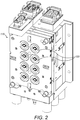
- Injection unit includes a fixed plate 110 ( FIG. 2 ) carrying, in this example, eight tool halves 120. As illustrated in FIG. 3 , each tool half 120 includes an injection nozzle 130, a thermocouple 140, a tool portion 150, and a stripper plate at the front surface of fixed plate 110 ( FIG. 2 ), which is arranged to move forward a few millimeters to eject formed molds.
- Tool portion 150 includes an outermost surface 160 that, in the example shown in FIG. 3 , is concave and shaped to define a (convex) outer surface of a mold half to be formed in the injection cavity.
- a concave inner surface of a mold half is formed by providing a tool portion having an outermost surface that is convex. Coolant flow passages 165 are provided behind tool portion 150, passing approximately 4 mm from outermost surface 160 at their closest approach.
- the stripper plate defines a surface of peripheral regions 170 of the mold halves. The provision of peripheral regions 170 enables injection nozzle 130 and thermocouple 140 to be sited or located away from the center of tool portion 150, which in-turn makes room for coolant passages 165 to pass close to tool portion 150, where the surface of the contact lens mold half used to cast-mold the optic zone of a contact lens, is formed.
- the stripper plate is moveable from a rearward, mold-formation position, to a forward, mold-ejection position.
- Reciprocating unit 50 ( FIG. 4 ) comprises a mounting plate 190 mounted in a vertical orientation on a reciprocating drive 200.
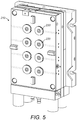
- mounting plate 190 carries a quick-change plate 210 that includes tool halves 220 that co-operate with tool halves 120 ( FIG. 2 ) of the injection unit, to form injection cavities for formation of the molds.
- quick-change plate 210 defines eight substantially cylindrical bushings 230 each carrying a collet 240 shown in FIG. 6 .
- Each bushing 230 includes coolant passages 250 around its outer circumference.
- Each collet 240 carries a tool insert 260.
- Each collet 240 has a front disc portion 270 and a frustoconical body portion 280.
- Frustoconical body portion 280 includes, toward its rear, an annular groove 290.
- Reciprocating unit 50 includes a clamp 300 having a distal clamping portion 310 that engages with groove 290 of collet 240 and secures collet 240 toward the rear of quick-change plate 210, away from the face of plate 210, to retain collet 240 in quick-change plate 210.
- This clamping prevents both leakage of coolant, and collet 240 from dropping out of quick-change plate 210 when quick-change plate 210 is not in contact with fixed plate 110.
- a tube 320 runs along the centre of frustoconical body portion 280 forming a coolant passage, with coolant passing inside the tube 320 from the rear of body portion 280 to the rear of tool insert 260, and then back towards the rear of body portion 280 along the outside of the tube 320
- Each collet 240 can be unclamped, removed, and replaced independently of other collets 240, enabling flexible interchange of collets 240, and each collet can carry a different tool insert 260.
- it is not necessary to replace the whole quick-change plate 210, nor is it necessary to replace individual tool inserts 260, which are vulnerable to damage, directly.
- Inserts 260 include an outermost surface 330 that is convex in this example, and that defines an optical-quality surface that in-turn defines a concave surface of a mold half.
- the surface of the mold half in-turn defines an optical surface of a contact lens to be formed using the mold half.
- Optical surface 330 and an outermost portion of collet 240 together define an inner surface of a mold half to be formed in the injection cavity.
- the injection cavity for forming the mold half is defined, on one hand, by the outermost surface of tool portion 150 and the stripper plate carried in each tool half 120 of fixed plate 110 of the injection unit.
- the mold half is also defined by the outermost portion of collet 240 and optical-quality surface 330 of tool insert 260 carried by quick-change plate 210 on reciprocating unit 50.
- the tool providing the optical surface in the mold is in quick-change plate 210 and not in fixed plate 110 that instead has the injection-molding parts. Consequently, a different optical surface can be readily provided in a mold by changing tool insert 260, without a need to disassemble the injection mechanism.
- a screw In injection unit, a screw is arranged to transport pellets from a pellet inlet to a nozzle. The pellets then pass into the heated inlet bush, where they are heated beyond their melting point, and the resultant liquid polymer flows into a manifold and then to the outlets of the manifold and into ( FIG. 3 ) injection nozzles 130 of tool halves 120 of fixed plate 110. The melted polymer then passes into the injection cavity for forming the mold half.
- Heating is provided by a coil around injection nozzle 130.
- Thermocouple 140 arranged on the opposite side of tool portion 150 from injection nozzle 130, is used to monitor the temperature of the injected polymer. Heating of nozzle 130 is controlled to ensure that the liquid polymer is injected into each of the eight injection cavities at the same temperature, and hence at the same flow rate.
- Non-constant flow rates result in stresses in the formed mold, which in turn result in deformations and inconsistencies in contact lenses formed from the molds, for example, different levels of fit, different radii, and hence, different powers.
- Careful control of pressure and cooling gives consistency and uniformity; in contrast, poor control can result in a need to stop injection, selectively, into cavities for which the flow rate has deviated too far from a target value.
- Coolant for example, water
- coolant flow passages 165, 250 in tool halves 120, 220 pass close to the outermost surface of tool portion 150 and the optical-quality surface of tool insert 260 carried by quick-change plate 210, respectively.
- Such an arrangement provides direct cooling in the portion of the mold half that forms the optic zone of the lens as the mold half forms in the cavity. (Rapid cooling of nucleated material results in good quality, uniform molds.
- reciprocating drive 200 moves mounting plate 190, and with it, quick-change plate 210, away from fixed plate 110, opening the cavity.
- the newly formed mold remains in tool portion 150 in fixed plate 110.
- the stripper plate moves from the rearward, mold-forming position, to the forward, mold-ejecting position, pushing on the peripheral regions of the mold to eject it from the tool portion in fixed plate 110.
- one or more ejector pins can be used to eject the mold.
- reciprocating drive 200 moves quick-change plate 210 into contact with fixed plate 110 of the injection unit, forming the injection cavities. Molten polymer is injected and cooled, and eight molds are thereby formed. Reciprocating drive 200 then moves quick-change plate 210 out of contact with fixed plate 110 of the injection unit, leaving the mold halves in tool portions 150 of fixed plate 110.
- a collet-exchange subsystem When it is desired to change the tool or tool assembly in order to change the power or type of contact lenses being manufactured, a collet-exchange subsystem is activated.
- the collet-exchange subsystem comprises a collet store 810 ( FIG. 11 ) and a collet-exchange robot 820 ( FIG. 7 ).
- collet-exchange robot 820 removes a collet 220 from quick-change plate 210, and replaces it with a replacement collet 240 from collet store 810.
- collet exchange robot 820 comprises a drive unit 850 carrying an arm 860, at a distal end of which is rotatably mounted a collet extraction head 870.
- Drive unit 850 is mounted on a first rail 830, along which drive unit 850 is translated by a first linear motor 835.
- First rail 830 is itself mounted on a rail pair 840 that is perpendicular to first rail 830.
- First rail 830, and together with it, drive unit 850, are translated along rail pair 840 by a second linear motor 845.
- Such a mounting arrangement enables drive unit 850 to be moved to anywhere within a two-dimensional, horizontal area.
- Drive unit 850 includes two electric motors 880, 890 mounted on first rail 830 by a bracket 855. Arm 860 is rotatably mounted on an axle passing into bracket 855.
- the drive shaft of lower electric motor 880 carries a pulley 881 which is connected via a drive belt (not shown) to a pulley (not shown) rigidly connected to the axle on which arm 860 is mounted, so that operation of lower electric motor 880 causes arm 860 to rotate about the axle.
- the drive shaft of upper motor 890 carries a pulley 891 that is connected via a drive belt 892 to a pulley 893 that is rigidly connected to head 870. Operation of upper electric motor 890 thereby causes head 870 to rotate.
- FIG. 8 illustrates how collets 900 mounted in a plate 910 are accessed. Movement of drive unit 850 along first rail 830 moves collet extraction head 870 between vertical columns of collets 900. Rotation of arm 860, in combination with movement of drive unit 850 along first rail 830, moves collet extraction head 870 between horizontal rows of collets 900. Movement of drive unit 850 forward and backward along rail pair 840 moves collet extraction head 870 toward and away from plate 910, permitting insertion and extraction of collets 900 from plate 910.
- Arm 860 can also rotate about 180 degrees around an axis of rotation, from a first orientation in which collet extraction head 870 is on a first side of arm 860, and a second orientation in which collet extraction head 870 is on a second side of arm 860.
- collet extraction head 870 can be moved in three dimensions, enabling access to each collet 900.
- arm 860 in the first orientation has access to collets 240 in quick-change plate 210, and, in the second orientation, it has access to collets 240 in collet store 810.
- collet exchange robot 820 is able to remove collets 240 from quick-change plate 210, and transfer them to, and insert them into, collet store 810, and vice versa.
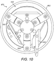
- Collet extraction head 870 ( FIGS. 9 and 10 ) comprises an axle 920, pulley 893, and gripping portion 940.
- Gripping portion 940 includes three gripping fingers 950.
- a proximity sensor 930 is also provided.
- gripping fingers 950 are sized and configured to grip a groove 272 that runs around the circumference of front disc portion 270 of collet 240. When gripping portion 940 is in position to grip collet 240, fingers 950 close into groove 272.
- Collet extraction head 870 can thus grip a collet 240 and carry it from quick-change plate 210 to collet store 810, or vice versa.
- collet store 810 includes a housing 960 mounted on a turntable 970.
- Housing 960 carries holding plates 980 that define ten circular apertures 990, each sized and configured to receive a collet 240.
- collet 240 in the quick-change plate 210 When a collet 240 in the quick-change plate 210 is to be changed, the fixed plate 110 and the quick change plate 210 are separated and cooling water is evacuated from the coolant passages 250 and the tube 320. Air is blown through the coolant passages 250 and the tube 320 to remove residual water. Clamp 300 is released, leaving collet 240 free to be removed by exchange robot 820. Collet extraction head 870 of collet exchange robot 820 is then moved to a position in front of the particular collet 240 to be changed. Extraction head 870 is moved forward, and gripping fingers 950 grip groove 272 of collet 240.
- Exchange robot 820 moves backward, extracting collet 240 from quick-change plate 210, and then moves itself and extraction head 870 so that extraction head 870 is at a position in front of an empty aperture 990 in collet store 810.
- Robot 820 moves forward, and collet 240 is released from fingers 950, into aperture 990.
- Extraction head 870 is then moved to a position in front of replacement collet 240 that is to replace the collet that has just been moved. Gripping fingers 950 grip replacement collet 240 and extract it from collet store 810.
- Extraction head 870 is moved, with replacement collet 240, to the position in front of the quick-change plate from which it extracted moved collet 240.
- Replacement collet 240 is inserted into quick-change plate 210.
- Clamp 300 re-engages with annular groove 290 toward the rear of collet 240, clamping replacement collet 240 in place.
- Gripping fingers 950 release collet 240.
- Robot 820 moves out of the way, to a resting location. The supply of water is restored to the coolant passages 250 and the tube 320 and production of molds restarts.
- the steps involved in changing the collet 240 including the evacuation and re-supply of cooling water, are synchronised under the control of a central controller (not shown) to minimize the time required for the exchange.
Landscapes
- Engineering & Computer Science (AREA)
- Mechanical Engineering (AREA)
- Manufacturing & Machinery (AREA)
- Health & Medical Sciences (AREA)
- Ophthalmology & Optometry (AREA)
- Moulds For Moulding Plastics Or The Like (AREA)
Description
- The present disclosure relates to methods of, and apparatus for, manufacturing, by injection molding, mold halves suitable for use in forming contact lenses. In particular, it relates to apparatus and methods for exchanging tools and/or tool assemblies in injection molding machines in order to manufacture mold halves for different powers or types of contact lenses.
- Various methods of manufacturing contact lenses are known, including spin casting, lathing (for example, by diamond turning) and cast molding (for example, using injection molded mold halves). Manufacture of soft contact lenses, including conventional hydrogel and silicone hydrogel contact lenses, presents particular difficulties, as contact lenses are delicate. Surfaces and edges of a contact lens, including surfaces providing vision correction, as well as surfaces and edges used to cast mold surfaces of a contact lens, must be manufactured and maintained to optical precision and all surfaces and edges must be manufactured within tight tolerances to provide a desired level of vision correction and/or provide a desired cosmetic appearance to the eye, and to avoid potential issues with discomfort or even damage to the eye of the wearer. Using high speed manufacturing lines, contact lenses can be manufactured in very large numbers, for example, tens of thousands each day. Increases in the rate of manufacture of contact lenses can be expected to bring down the cost of each lens. It is important, however, that increased rates of manufacture do not compromise the quality of the lenses produced.
-
US5445511 discloses apparatus, preferably applicable to a molding machine using the core change type dies, capable of pushing out an inserted core from a mother mold, thereby facilitating a core extracting operation by robots. A mother mold of a complementary die in the core change type dies is constituted by a main body and an intermediate plate which is disposed behind the main body and is movable in both the forward and backward directions. A core fixing and releasing mechanism is provided on the intermediate plate. Furthermore, there is provided a push-out device disposed in a clearance formed between the main body and the intermediate plate when the intermediate plate is shifted rearward. The push-out device has its one surface abutting on a front surface of a core and another surface abutting on a rear surface of the main body. The push-out device is attached to a distal end of an arm of a robot, combined with a molding machine, so that the push-out device is slidable in both the forward and backward directions and is urged rearward, if necessary. - JPH01275111 (A) discloses that inserts to be attached on a mold body are held with the arm of a robot, moved horizontally from left to right and T-clamp members are joined with the tip ends of T-grooves of the inserts. Thereafter, the piston rod of a hydraulic cylinder is moved upward to pull up the insert while the piston rod of a hydraulic cylinder is moved downward to pull down the insert, and then these inserts are placed into the insert engagement parts. The inserts are moved in the direction orthogonal to a parting line and put into insert engagement parts which have a shape and size suitable to the insert to attach them to upper and lower mold bodies with a predetermined positioning precision.
- In accordance with the present disclosure, contact lenses can be manufactured by cast molding using single-use mold halves. Mold halves of a first type and of a second type can be manufactured. The mold halves can be shaped so that a mold half of the first type can be brought together with a mold half of the second type to define a cavity there between, the cavity having the shape of a contact lens that is to be manufactured. For example, the mold halves of the first type can be female mold halves, each having a concave surface of optical quality and that defines the front of the contact lens. The mold halves of the second type can then be male mold halves, each having a convex surface of optical quality and that defines the back of the contact lens. In forming the lens, a polymerizable composition can be placed in the female mold half. The male mold half can then be mated with the female mold half, defining a cavity in which the polymerizable composition is contained. The polymerizable composition can be cured in the cavity, for example, by exposure to ultraviolet light and/or by heating, and a polymerized contact lens body is thereby formed. The mold halves can then be separated and the contact lens body can be released or removed. The contact lens body can then be subjected to further processing, for example, hydration, to form a finished contact lens. The mold halves can be disposed of during the manufacturing process.
- As the mold halves are typically single-use, the present disclosure provides an apparatus and method so that they can be made as efficiently as possible, without loss of quality. Contact lenses of several different powers can be made to provide lenses for different patients with different spherical refractive errors, i.e., different amounts of myopia or hyperopia. Toric lenses (lenses providing cylindrical correction), multifocal lenses, or lenses of other specific forms, can also be made. As it is not practical to provide a separate manufacturing line for each power of each type of lens, the apparatus and method of the present disclosure can use interchangeable tools or tool assemblies that can be robotically exchanged in order to manufacture different powers or types of lenses. The apparatus and method of the present disclosure reduce tool exchange time, maximize production, facilitate high speed manufacturing of contact lenses, and enable high speed manufacturing of a wide variety of powers and types of lenses.
- A first aspect of the present disclosure provides apparatus for manufacturing mold halves for use in the manufacture of contact lenses. The apparatus comprises the features set out in claim 1 below.
- A second aspect of the disclosure provides a method of manufacturing a contact lens. The method comprises the steps set out in claim 4 below.
- Using the robot to remove the first collet from the plate, using the robot to transport and insert the first collet, using the robot to remove the replacement collet, using the robot to transport and insert the replacement collet, or any combination thereof, can comprise moving a collet extraction head of the robot in three dimensions. Using the robot to remove the first collet from the plate, using the robot to transport the first collet and insert the first collet in the collet store, using the robot to remove the replacement collet from the collet store, using the robot to transport the replacement collet and insert the replacement collet in the plate, or any combination thereof, can comprise using a position sensor located on the robot. The position sensor can be located on the collet extraction head of the robot. Using the robot to remove the first collet from the plate, using the robot to transport the first collet and insert the first collet into the collet store, using the robot to remove the replacement collet from the collet store, using the robot to transport the replacement collet and insert the replacement collet in the plate, or any combination thereof, can comprise both moving the collet extraction head of the robot in three dimensions, and using a position sensor located on the robot.
-
-
FIG. 1 is a perspective view of an apparatus according to an exemplary embodiment of the invention. -
FIG. 2 is a fixed-plate apparatus forming part of an injection-molding apparatus, in accordance with an embodiment of the invention. -
FIG. 3 is a partial cross-sectional view through a tool half of a fixed-plate apparatus, in accordance with an embodiment of the invention. -
FIG. 4 is a cut-away view of a reciprocating unit of an injection-molding apparatus, in accordance with an embodiment of the invention. -
FIG. 5 is a perspective view of a mounting plate forming part of a reciprocating unit, in accordance with an embodiment of the invention. -
FIG. 6 is a partial cross-sectional view through a tool half of a mounting plate, in accordance with an embodiment of the invention. -
FIG. 7 is a perspective view of a collet-exchange robot, in accordance with an embodiment of the invention. -
FIG. 8 is a side view of a collet-exchange robot and a two-dimensional array of collets arranged in a vertical plane, in accordance with an embodiment of the invention. -
FIG. 9 is a side view of a collet extraction head including gripping fingers, in accordance with an embodiment of the invention. -
FIG. 10 is a front view of the collet extraction head ofFig. 9 . -
FIG. 11 is a perspective view of a collet store on a turntable, in accordance with an embodiment of the invention. - A first aspect of the present disclosure provides
an apparatus for manufacturing mold halves for use in the manufacture of contact lenses, the apparatus comprising: an injection-molding apparatus including a plate, a removable collet in the plate; and a collet-exchange robot comprising at least one collet extraction head; characterized in that: a tool half is mounted in the removable collet; the apparatus includes a collet store for storing at least one removable collet configured to be inserted into the plate; the collet-exchange robot is configured to grip the removable collet from the plate, move the removable collet to the collet store, insert the removable collet into the collet store, grip a replacement collet from the collet store, move the replacement collet to the plate, and insert the replacement collet into the plate; wherein the injection-molding apparatus comprises a clamp configured to hold the removable collet in the plate and the removable collet includes a frustoconical rear portion and a circumferential groove upon which the clamp acts; and wherein the collet store comprises a housing for receiving a plurality of removable collets, and a turntable on which the housing is mounted, the turntable being rotatable from a first position wherein a removable collet can be manually loaded into the housing, to a second position wherein the removable collet can be removed from the collet store by the collet-exchange robot. - The skilled person will understand that specific features of embodiments of the invention described herein that are not incompatible with each other can be present in in any combination in example embodiments of the invention.
- Thus, for example, the collet extraction head can be a collet extraction head that can be moved in three dimensions. In other words, the robot can be configured to move the collet extraction head not merely along a line or plane but in three-dimensional space, for example as defined by orthogonal x, y, and z axes. The collet extraction head of the collet-exchange robot can be rotatably mounted on the robot. Each collet extraction head of the collet-exchange robot can be rotatably mounted on the robot. The collet extraction head of the robot can comprise a gripping portion. Each collet extraction head of the robot can comprise a gripping portion. When the robot comprises a collet extraction head, the apparatus can further comprise a rail arrangement, and the robot can be configured to move from a position on the rail arrangement in which the collet exchange head is in front of the plate, to a position on the rail arrangement in which the collet extraction head is in front of the collet store.
- [DELETED]
- The apparatus can be any contact lens mold assembly embodying the invention, wherein the circumferential groove isa circumferential groove upon which a plate clamp is arranged to act.
- [DELETED]
- Herein, reference is made to mold halves, but it is to be understood that, although two mold halves may complement each other and together form a mold assembly, each mold half is not necessarily half of, or 50% of, the mold assembly. One mold half can comprise 20%, 30%, 40%, 45%, or the like, of a mold assembly while the other mold half can comprise 80%, 70%, 60%, 55%, or the like, of the mold assembly. Accordingly, while the two mold halves can make one whole mold assembly, it is to be understood that the two mold halves neither have to be of the same size nor do they have to be mirror images of one another. Similarly, while reference is made herein to tool halves, it is to be understood that two tool halves, that complement each other and together define a mold cavity, do not have to be of the same size or mirror images of one another.
- The skilled person will understand that the features disclosed in the following paragraphs can be combined in any combination in example embodiments of the invention, and can be combined in any combination with the features disclosed above.
- The collet of the apparatus can be a first collet or a replacement collet. The tool half can be carried in a front portion of the collet. The collet can include a disc-shaped front portion. The collet can include a frustoconical rear portion. The collet can include a disc-shaped front portion and a frustoconical rear portion. The circumferential groove can be, for example, around the disc-shaped front portion, if present.
- Each plate of the at least one plate of the apparatus can comprise a plurality of collets. The plurality of collets can be a plurality of first collets or a plurality of replacement collets. The plurality of collets carried by the at least one plate can be arranged in a two-dimensional array.
- The collet store of the apparatus can comprise a plurality of collets. The plurality of collets can comprise a plurality of first collets or a plurality of replacement collets. The plurality of collets carried by the collet store can be arranged in a two-dimensional array.
- The at least one collet extraction head of the robot can be rotatably mounted on the robot. The collet exchange robot can comprise a drive unit carrying an arm, at a distal end of which is mounted a collet extraction head. The arm can be rotatably mounted on the drive unit. The arm can be rotatable from a first orientation in which the collet extraction head is on a first side of the drive unit, to a second orientation in which the collet extraction head is on a second side of the drive unit. The collet extraction head can be rotatably mounted on the arm. The collet extraction head can, for example, rotate up to 180 degrees. The apparatus can include a rail arrangement, upon which the drive unit is mounted, such that the robot is configured to move from a position on the rail arrangement, in which the collet extraction head is in front of the plate, to a position on the rail arrangement in which the collet extraction head is in front of the collet store. Thus, in the first orientation, the collet extraction head can have access to the collets in the quick-change plate, and, in the second orientation, the arm can have access to the collets in the collet store. Thus, in use, the collet exchange robot can be able to access collets from the plate, and transfer them to and insert them into, the collet store, and vice versa.
- The collet extraction head can comprise a gripping portion. The gripping portion can include a sensor. The sensor can comprise a proximity sensor. The gripping portion can include a plurality of (for example, three) gripping fingers. The gripping fingers can be sized and configured to grip a circumferential groove in a collet.
- The collet can have multiple circumferential grooves, or a single circumferential groove. The plate clamp and the gripping fingers of the collet extraction head can both be configured to grab, secure, fit into, or otherwise act on, the same circumferential groove of the collet or different, respective, circumferential grooves of the collet.
- [DELETED]
- The injection-molding apparatus, collet exchange robot, and collet store turntable can be controlled by a control unit. The control unit can control movement of the collet exchange robot arm, the collet extraction head, the drive units carrying the arm, the gripping features of the collet extraction head, the gripping features of the injection-molding apparatus, and the collet store turntable. The control unit can comprise one or more microprocessors for controlling the various drive units and motors, including those of the collet exchange robot and of the collet store turntable. Each motor and drive unit can be configured to communicate with the control unit. The one or more microprocessors can each have and execute control logic software. The drive units and motors can be connected via wiring to the control unit. The control unit can be located or housed proximate to the motors and drive units, or it can be remotely located.
- The control unit can be connected to the injection-molding apparatus, collet exchange robot, and collet store turntable via at least one USB connection, wired and/or wireless connection, Ethernet connection, or any combination thereof. The control unit can receive control signals from a graphical user interface, from a control board, or the like. An operator can operate an operator control unit (OCU) for programming the control unit or for starting or stopping a manufacturing operation. Control signals generated by the OCU, automatically or in response to an operator's input, can be processed and controlled by the control unit, and delivered to the drive units and motors. The drive units and motors can communicate directly with the OCU. The injection-molding apparatus, collet exchange robot, and collet store turntable can be controlled by an autonomous control program in one or more microprocessor, giving the apparatus microprocessor autonomous capability to maneuver or manipulate the injection-molding apparatus, collet exchange robot, and collet store turntable. Commands can come from the Internet via Wi-Fi, remote computer terminal, GPRS modem, satellite phone, mobile phone, infrared, Ethernet, Firewire, other wireless or wired connection protocols, or combinations thereof.
- A second aspect of the disclosure provides a method of manufacturing a contact lens, comprising: using a robot to remove a first collet from a plate in an injection-molding apparatus; using the robot to transport a replacement collet to the plate and insert the replacement collet into the plate; and forming a contact lens mold half in a second injection-molding cavity; characterized by: using the robot to transport the first collet to a collet store and insert the first collet into the collet store; and using the robot to remove the replacement collet from the collet store, the replacement collet comprising a second tool half defining at least a portion of the second injection-molding cavity for molding a contact lens mold half; and in that: the first collet comprising a first tool half mounted therein, the first tool half defining at least a portion of a first injection-molding cavity for molding a contact lens mold half; the first collet includes a frustoconical rear portion and a circumferential groove and is held in place in the plate with a clamp acting upon the circumferential groove, and the method further comprises releasing the clamp from holding the first collet prior to removing the first collet from the plate; and the collet store comprises a housing for receiving a plurality of removable collets, and a turntable on which the housing is mounted, the turntable being rotatable from a first position wherein a removable collet can be manually loaded into the housing, to a second position wherein the removable collet can be removed from the collet store by the collet-exchange robot.
- Using the robot to remove the first collet from the plate, using the robot to transport and insert the first collet, using the robot to remove the replacement collet, using the robot to transport and insert the replacement collet, or any combination thereof, can comprise moving a collet extraction head of the robot in three dimensions. Using the robot to remove the first collet from the plate, using the robot to transport the first collet and insert the first collet in the collet store, using the robot to remove the replacement collet from the collet store, using the robot to transport the replacement collet and insert the replacement collet in the plate, or any combination thereof, can comprise using a position sensor located on the robot. The position sensor can be located on the collet extraction head of the robot. Using the robot to remove the first collet from the plate, using the robot to transport the first collet and insert the first collet into the collet store, using the robot to remove the replacement collet from the collet store, using the robot to transport the replacement collet and insert the replacement collet in the plate, or any combination thereof, can comprise both moving the collet extraction head of the robot in three dimensions, and using a position sensor located on the robot.
- As already set out in respect of the first aspect of the invention, the skilled person will understand that specific features of embodiments of the invention described herein that are not incompatible with each other can be present in in any combination in example embodiments of the invention.
- The method can be any method embodying the invention, further comprising the step of stopping production of the molds in the injection-molding apparatus before using the robot to remove the first collet from the plate. The method can further comprise re-starting production of the molds in the injection-molding apparatus after using the robot to transport the replacement collet and to insert the replacement collet into the plate. Forming a contact lens mold half in the second injection-molding cavity can comprise forming a plurality of contact lens mold halves.
- The method can be any method embodying the invention, wherein using the robot to remove the first collet from the plate comprises: moving a collet extraction head of the robot to a position in front of the first collet; moving the collet extraction head forwards toward the first collet; gripping the first collet with the extraction head; and moving the collet extraction head backwards, thereby extracting the first collet from the plate. Moving the collet extraction head of the robot to a position in front of the first collet can comprise determining a distance from the extraction head to the first collet, or from the extraction head to the plate. Determining the distance can comprise using a proximity sensor on the extraction head to determine the distance from the extraction head to the first collet. Using the robot to remove the first collet from the plate can comprise rotating the collet extraction head, for example, rotating the collet extraction head around an axis of rotation by an amount of from 90 degrees to 180 degrees.
- The method can be any method embodying the invention, wherein gripping the first collet with the extraction head comprises gripping the first collet at a circumferential groove formed in the first collet.
- The method can be any method embodying the invention, wherein coolant is removed from coolant passages associated with the first collet, prior to the removal of the first collet from the plate, and resupplied to said coolant passages after insertion of the replacement collet into the plate. Advantageously, the removal and resupply of the coolant can be synchronized with the movement of the robot, for example to reduce the time required to exchange the first collet and the replacement collet, and hence to reduce downtime of the injection molding apparatus.
- The method can further comprise clamping the replacement collet into the plate from which the first collet was extracted. The method can further comprise moving the robot to a resting location after using the robot to insert the replacement collet in the plate.
- The method can be any method embodying the invention, wherein using the robot to transport the first collet and insert the first collet into the collet store comprises moving the collet extraction head of the robot to a position in front of an empty aperture in the collet store; moving the collet extraction head forward, toward the empty aperture; and releasing the first collet into the empty aperture. Moving the collet extraction head of the robot to a position in front of the empty aperture can comprise determining a distance from the extraction head to the aperture, or from the extraction head to the collet store. Determining the distance can comprise using a proximity sensor on the extraction head to determine the distance from the extraction head to the aperture. Using the robot to insert the first collet into the collet store can comprise rotating the collet extraction head of the robot by an amount of from 90 degrees to 180 degrees.
- The method can be any method embodying the invention, wherein using the robot to transport the replacement collet comprises moving the collet extraction head of the robot to a position in front of the replacement collet; gripping the replacement collet with the collet extraction head; moving the collet extraction head to the position in front of the plate from which the first collet was extracted; and inserting the replacement collet into the plate. Moving the collet extraction head of the robot to a position in front of the replacement collet can comprise determining a distance from the extraction head to the first collet, or from the extraction head to the plate. Determining the distance can comprise using a proximity sensor on the collet extraction head in determining the distance. The inserting the replacement collet into the plate can comprise rotating the collet extraction head of the robot by an amount of from 90 degrees to 180 degrees.
- The method can be any method embodying the invention, wherein gripping the replacement collet with the collet extraction head comprises gripping the replacement collet at a circumferential groove formed in the replacement collet.
- The method can be any method embodying the invention, wherein further comprising the steps of providing a complementary contact lens mold half; filling a polymerizable lens-forming composition into a concave lens-forming surface of the mold half or into the complementary mold half; combining the mold half and the complementary mold half to form a mold assembly having a lens-shaped cavity there between, containing the polymerizable composition; curing the polymerizable composition in the filled mold assembly, to form a polymeric lens body, by polymerizing the lens-forming composition in the lens-shaped cavity; demolding and delensing the polymeric lens body from both the mold half and the complementary mold half; optionally washing, extracting, hydrating, or any combination thereof, the released polymeric lens body; placing the released polymeric lens body in a contact lens package, optionally along with packaging solution; sealing the contact lens package; and sterilizing the sealed contact lens package to form a finished contact lens package containing a finished contact lens.
- The skilled person will understand that the features disclosed in the following paragraphs may similarly be combined in any combination in example embodiments of the invention.
- The method can include the step of stopping production of the molds in the injection-molding apparatus, for example, to exchange a collet. Forming a contact lens mold half in the second injection-molding cavity can comprise injection-molding a female contact lens mold half, or a male contact lens mold half. Forming a contact lens mold half can comprise injection-molding a plurality of contact lens mold halves.
- Using the robot to remove the first collet from the plate can comprise moving a collet extraction head of the robot to a position in front of the first collet; moving the collet extraction head forward, toward the first collet; gripping the first collet with the collet extraction head; and moving the collet extraction head backward, extracting the first collet from the plate. Gripping the first collet with the collet extraction head can comprise gripping the first collet at a circumferential groove formed in the first collet. Using the robot to transport the first collet and insert the first collet into the collet store can comprise: moving the collet extraction head so that the collet extraction head is in a position in front of an empty aperture in the collet store; moving the collet extraction head forward, toward the empty aperture; and releasing the first collet into the empty aperture. Using the robot to transport the replacement collet can comprise: moving the collet extraction head to a position in front of the replacement collet; gripping the replacement collet with the collet extraction head; moving the collet extraction head to a position in front of the plate from which the first collet was extracted; and inserting the replacement collet into the plate. The replacement collet can be inserted into the same position in the plate, from where the first collet was removed, or inserted into a different position in the plate. Gripping the replacement collet with the collet extraction head can comprise gripping the replacement collet at a circumferential groove formed in the replacement collet. The method can further comprise releasing a clamp holding the first collet in place in the plate. The method can further comprise clamping the replacement collet into the plate from which the first collet was extracted. The method can further comprise moving the robot to a resting location after using the robot to insert the replacement collet into the plate.
- A collet extraction head of the robot can be moved to a position in front of the collet that is to be removed from the plate. The extraction head can be moved forward, toward the collet that is to be removed from the plate. The collet extraction head can grip the collet, for example, in a circumferential groove of the collet. A clamp holding the collet in place in the plate can be released, leaving the collet free to be removed from the plate by the robot. The collet extraction head can move backward, extracting the collet from the plate. The robot can move the collet extraction head so that the collet extraction head is at a position in front of an empty aperture in the collet store. The collet extraction head can be moved forward, toward the empty aperture. The collet can be released into the empty aperture. The collet extraction head can be moved to a position in front of the replacement collet. The collet extraction head can grip the replacement collet. The collet extraction head can move backward, extracting the replacement collet from the collet store. The collet extraction head can be moved to a position in front of the plate from which it extracted the first collet. The robot can insert the replacement collet into the plate. The replacement collet can be clamped in place in the plate, for example, by action of a clamp acting on a circumferential groove of the replacement collet. The clamp can be part of the injection-molding apparatus, for example, a part of the plate. The robot can move to a resting location after inserting the replacement collet into the plate, and production of mold halves can be restarted.
- The method can further comprise the steps of: providing a complementary contact lens mold half; filling a polymerizable lens-forming composition into a concave lens-forming surface of the mold half or of a complementary mold half; combining the mold half and the complementary mold half to form a mold assembly having a lens-shaped cavity there between, containing the polymerizable composition; curing the polymerizable composition in the filled mold assembly to form a polymeric lens body by polymerizing the lens-forming composition in the lens-shaped cavity; demolding and delensing the polymeric lens body from both the mold half and the complementary mold half; optionally washing, extracting, hydrating, or any combination thereof, the released polymeric lens body; placing the released polymeric lens body in a contact lens package, optionally along with packaging solution; sealing the filled contact lens package; and sterilizing the sealed contact lens package to form a finished contact lens package containing a finished contact lens.
- With reference to the drawings,
FIG. 1 shows anexemplary apparatus 10 for manufacturing molds for use in forming a contact lens.Apparatus 10 includes an injection-molding apparatus 20 and a take-outcell 30 housing a collet store and a collet-exchange robot. Injection-molding apparatus 20 includes an injection unit and a reciprocating unit 50 (FIG. 4 ). - Injection unit includes a fixed plate 110 (
FIG. 2 ) carrying, in this example, eight tool halves 120. As illustrated inFIG. 3 , eachtool half 120 includes aninjection nozzle 130, athermocouple 140, atool portion 150, and a stripper plate at the front surface of fixed plate 110 (FIG. 2 ), which is arranged to move forward a few millimeters to eject formed molds.Tool portion 150 includes anoutermost surface 160 that, in the example shown inFIG. 3 , is concave and shaped to define a (convex) outer surface of a mold half to be formed in the injection cavity. In other, otherwise identical apparatus associated with this apparatus, a concave inner surface of a mold half is formed by providing a tool portion having an outermost surface that is convex.Coolant flow passages 165 are provided behindtool portion 150, passing approximately 4 mm fromoutermost surface 160 at their closest approach. The stripper plate defines a surface ofperipheral regions 170 of the mold halves. The provision ofperipheral regions 170 enablesinjection nozzle 130 andthermocouple 140 to be sited or located away from the center oftool portion 150, which in-turn makes room forcoolant passages 165 to pass close totool portion 150, where the surface of the contact lens mold half used to cast-mold the optic zone of a contact lens, is formed. The stripper plate is moveable from a rearward, mold-formation position, to a forward, mold-ejection position. - Reciprocating unit 50 (
FIG. 4 ) comprises a mountingplate 190 mounted in a vertical orientation on areciprocating drive 200. - As shown in
FIGS. 4-6 , mountingplate 190 carries a quick-change plate 210 that includes tool halves 220 that co-operate with tool halves 120 (FIG. 2 ) of the injection unit, to form injection cavities for formation of the molds. Specifically, quick-change plate 210 defines eight substantiallycylindrical bushings 230 each carrying acollet 240 shown inFIG. 6 . Eachbushing 230 includescoolant passages 250 around its outer circumference. Eachcollet 240 carries atool insert 260. Eachcollet 240 has afront disc portion 270 and afrustoconical body portion 280.Frustoconical body portion 280 includes, toward its rear, anannular groove 290. Reciprocatingunit 50 includes aclamp 300 having adistal clamping portion 310 that engages withgroove 290 ofcollet 240 and securescollet 240 toward the rear of quick-change plate 210, away from the face ofplate 210, to retaincollet 240 in quick-change plate 210. This clamping prevents both leakage of coolant, andcollet 240 from dropping out of quick-change plate 210 when quick-change plate 210 is not in contact with fixedplate 110. Atube 320 runs along the centre offrustoconical body portion 280 forming a coolant passage, with coolant passing inside thetube 320 from the rear ofbody portion 280 to the rear oftool insert 260, and then back towards the rear ofbody portion 280 along the outside of thetube 320 - Each
collet 240 can be unclamped, removed, and replaced independently ofother collets 240, enabling flexible interchange ofcollets 240, and each collet can carry adifferent tool insert 260. In particular, it is not necessary to replace the whole quick-change plate 210, nor is it necessary to replace individual tool inserts 260, which are vulnerable to damage, directly. -
Inserts 260 include anoutermost surface 330 that is convex in this example, and that defines an optical-quality surface that in-turn defines a concave surface of a mold half. The surface of the mold half in-turn defines an optical surface of a contact lens to be formed using the mold half.Optical surface 330 and an outermost portion ofcollet 240 together define an inner surface of a mold half to be formed in the injection cavity. - Thus, the injection cavity for forming the mold half is defined, on one hand, by the outermost surface of
tool portion 150 and the stripper plate carried in eachtool half 120 of fixedplate 110 of the injection unit. On the other hand, the mold half is also defined by the outermost portion ofcollet 240 and optical-quality surface 330 oftool insert 260 carried by quick-change plate 210 on reciprocatingunit 50. - In this arrangement, the tool providing the optical surface in the mold is in quick-
change plate 210 and not in fixedplate 110 that instead has the injection-molding parts. Consequently, a different optical surface can be readily provided in a mold by changingtool insert 260, without a need to disassemble the injection mechanism. - In injection unit, a screw is arranged to transport pellets from a pellet inlet to a nozzle. The pellets then pass into the heated inlet bush, where they are heated beyond their melting point, and the resultant liquid polymer flows into a manifold and then to the outlets of the manifold and into (
FIG. 3 )injection nozzles 130 oftool halves 120 of fixedplate 110. The melted polymer then passes into the injection cavity for forming the mold half. - Heating is provided by a coil around
injection nozzle 130.Thermocouple 140, arranged on the opposite side oftool portion 150 frominjection nozzle 130, is used to monitor the temperature of the injected polymer. Heating ofnozzle 130 is controlled to ensure that the liquid polymer is injected into each of the eight injection cavities at the same temperature, and hence at the same flow rate. Non-constant flow rates result in stresses in the formed mold, which in turn result in deformations and inconsistencies in contact lenses formed from the molds, for example, different levels of fit, different radii, and hence, different powers. Careful control of pressure and cooling gives consistency and uniformity; in contrast, poor control can result in a need to stop injection, selectively, into cavities for which the flow rate has deviated too far from a target value. - Once the cavity is full of polymer and a desired hold pressure profile applied, the pins in
injection nozzles 130 are moved forward to shut offinjection nozzles 130, from the cavities, which stops the flow of polymer. Coolant, for example, water, is circulated throughcoolant flow passages 165 to cool the polymer and thereby form the mold.Coolant flow passages tool halves tool portion 150 and the optical-quality surface oftool insert 260 carried by quick-change plate 210, respectively. Such an arrangement provides direct cooling in the portion of the mold half that forms the optic zone of the lens as the mold half forms in the cavity. (Rapid cooling of nucleated material results in good quality, uniform molds. Without nucleation, slower cooling in the middle of the material can result, forming bigger crystals in the middle of the material.) Once the mold is formed, reciprocatingdrive 200moves mounting plate 190, and with it, quick-change plate 210, away from fixedplate 110, opening the cavity. The newly formed mold remains intool portion 150 in fixedplate 110. The stripper plate moves from the rearward, mold-forming position, to the forward, mold-ejecting position, pushing on the peripheral regions of the mold to eject it from the tool portion in fixedplate 110. In some embodiments, one or more ejector pins can be used to eject the mold. - In use, as described above, reciprocating
drive 200 moves quick-change plate 210 into contact with fixedplate 110 of the injection unit, forming the injection cavities. Molten polymer is injected and cooled, and eight molds are thereby formed. Reciprocatingdrive 200 then moves quick-change plate 210 out of contact with fixedplate 110 of the injection unit, leaving the mold halves intool portions 150 of fixedplate 110. - When it is desired to change the tool or tool assembly in order to change the power or type of contact lenses being manufactured, a collet-exchange subsystem is activated. The collet-exchange subsystem comprises a collet store 810 (
FIG. 11 ) and a collet-exchange robot 820 (FIG. 7 ). As will be described further below, collet-exchange robot 820 removes acollet 220 from quick-change plate 210, and replaces it with areplacement collet 240 fromcollet store 810. - As illustrated in
FIG. 7 ,collet exchange robot 820 comprises adrive unit 850 carrying anarm 860, at a distal end of which is rotatably mounted acollet extraction head 870.Drive unit 850 is mounted on afirst rail 830, along which driveunit 850 is translated by a firstlinear motor 835.First rail 830 is itself mounted on arail pair 840 that is perpendicular tofirst rail 830.First rail 830, and together with it,drive unit 850, are translated alongrail pair 840 by a secondlinear motor 845. Such a mounting arrangement enablesdrive unit 850 to be moved to anywhere within a two-dimensional, horizontal area. - A further degree of movement is provided by the mounting of
arm 860 ondrive unit 850, as shown inFIGS. 7 and8 .Drive unit 850 includes twoelectric motors first rail 830 by a bracket 855.Arm 860 is rotatably mounted on an axle passing into bracket 855. The drive shaft of lowerelectric motor 880 carries apulley 881 which is connected via a drive belt (not shown) to a pulley (not shown) rigidly connected to the axle on whicharm 860 is mounted, so that operation of lowerelectric motor 880 causesarm 860 to rotate about the axle. The drive shaft ofupper motor 890 carries apulley 891 that is connected via adrive belt 892 to apulley 893 that is rigidly connected to head 870. Operation of upperelectric motor 890 thereby causeshead 870 to rotate. -
Quick change plate 210 andcollet store 810 each presents to collet exchange robot 820 a two-dimensional array ofcollets 240, arranged in a vertical plane.FIG. 8 illustrates howcollets 900 mounted in aplate 910 are accessed. Movement ofdrive unit 850 alongfirst rail 830 movescollet extraction head 870 between vertical columns ofcollets 900. Rotation ofarm 860, in combination with movement ofdrive unit 850 alongfirst rail 830, movescollet extraction head 870 between horizontal rows ofcollets 900. Movement ofdrive unit 850 forward and backward alongrail pair 840 movescollet extraction head 870 toward and away fromplate 910, permitting insertion and extraction ofcollets 900 fromplate 910.Arm 860 can also rotate about 180 degrees around an axis of rotation, from a first orientation in whichcollet extraction head 870 is on a first side ofarm 860, and a second orientation in whichcollet extraction head 870 is on a second side ofarm 860. Thus,collet extraction head 870 can be moved in three dimensions, enabling access to eachcollet 900. In take-out cell 30 (FIG. 1 ),arm 860 in the first orientation has access tocollets 240 in quick-change plate 210, and, in the second orientation, it has access tocollets 240 incollet store 810. Thus, in use,collet exchange robot 820 is able to removecollets 240 from quick-change plate 210, and transfer them to, and insert them into,collet store 810, and vice versa. - Collet extraction head 870 (
FIGS. 9 and10 ) comprises anaxle 920,pulley 893, and grippingportion 940. Grippingportion 940 includes threegripping fingers 950. Aproximity sensor 930 is also provided. With reference also toFIG. 6 , grippingfingers 950 are sized and configured to grip agroove 272 that runs around the circumference offront disc portion 270 ofcollet 240. When grippingportion 940 is in position to gripcollet 240,fingers 950 close intogroove 272.Collet extraction head 870 can thus grip acollet 240 and carry it from quick-change plate 210 tocollet store 810, or vice versa. - As shown in
FIG. 11 ,collet store 810 includes ahousing 960 mounted on aturntable 970. Housing 960 carries holding plates 980 that define tencircular apertures 990, each sized and configured to receive acollet 240. - When a
collet 240 in the quick-change plate 210 is to be changed, the fixedplate 110 and thequick change plate 210 are separated and cooling water is evacuated from thecoolant passages 250 and thetube 320. Air is blown through thecoolant passages 250 and thetube 320 to remove residual water.Clamp 300 is released, leavingcollet 240 free to be removed byexchange robot 820.Collet extraction head 870 ofcollet exchange robot 820 is then moved to a position in front of theparticular collet 240 to be changed.Extraction head 870 is moved forward, andgripping fingers 950grip groove 272 ofcollet 240.Exchange robot 820 moves backward, extractingcollet 240 from quick-change plate 210, and then moves itself andextraction head 870 so thatextraction head 870 is at a position in front of anempty aperture 990 incollet store 810.Robot 820 moves forward, andcollet 240 is released fromfingers 950, intoaperture 990.Extraction head 870 is then moved to a position in front ofreplacement collet 240 that is to replace the collet that has just been moved. Grippingfingers 950grip replacement collet 240 and extract it fromcollet store 810.Extraction head 870 is moved, withreplacement collet 240, to the position in front of the quick-change plate from which it extracted movedcollet 240.Replacement collet 240 is inserted into quick-change plate 210.Clamp 300 re-engages withannular groove 290 toward the rear ofcollet 240, clampingreplacement collet 240 in place. Grippingfingers 950release collet 240.Robot 820 moves out of the way, to a resting location. The supply of water is restored to thecoolant passages 250 and thetube 320 and production of molds restarts. The steps involved in changing thecollet 240, including the evacuation and re-supply of cooling water, are synchronised under the control of a central controller (not shown) to minimize the time required for the exchange. - All patents and publications cited herein are incorporated herein by reference in their entireties.
- While the present disclosure has been described and illustrated with reference to particular embodiments, it will be appreciated by those of ordinary skill in the art that the disclosure lends itself to many different variations not specifically illustrated herein. By way of example only, certain possible variations are described herein.
- In the foregoing description, where integers or elements are mentioned which have known, obvious or foreseeable equivalents, then such equivalents are herein incorporated as if individually set forth. Reference should be made to the claims for determining the true scope of the present disclosure, which should be construed so as to encompass any such equivalents. It will also be appreciated by the reader that integers or features of the disclosure that are described as preferable, advantageous, convenient, or the like, are optional and do not limit the scope of the independent claims. Moreover, it is to be understood that such optional integers or features, while of possible benefit in some embodiments of the disclosure, may not be desirable, and can therefore be absent, in other embodiments.
Claims (14)
- An apparatus (10) for use in the manufacture of contact lenses, the apparatus (10) comprising:an injection-molding apparatus (20) including a plate (210), and a removable collet (240) in the plate (210);a collet-exchange robot (820) comprising at least one collet extraction head (870); andwhereinthe apparatus (10) includes a collet store (810) for storing at least one removable collet (240) configured to be inserted into the plate (210);CHARACTERISED IN THAT:a tool half (260) is mounted in the removable collet (240);the collet-exchange robot (820) is configured to grip the removable collet (240) from the plate (210), move the removable collet (240) to the collet store (810), insert the removable collet (240) into the collet store (810), grip a replacement collet (240) from the collet store (810), move the replacement collet (240) to the plate (210), and insert the replacement collet (240) into the plate (210);wherein the injection-molding apparatus comprises a clamp (300) configured to hold the removable collet (240) in the plate (210) and the removable collet (240) includes a frustoconical rear portion (280) and a circumferential groove (290) upon which the clamp (300) acts; and wherein the collet store (810) comprises a housing (960) for receiving a plurality of removable collets (240), and a turntable (970) on which the housing (960) is mounted, the turntable (970) being rotatable from a first position wherein a removable collet (240) can be manually loaded into the housing (960), to a second position wherein the removable collet (240) can be removed from the collet store (810) by the collet-exchange robot (820).
- The apparatus as claimed in claim 1, wherein the collet extraction head is rotatably mounted on the collet-exchange robot.
- The apparatus as claimed in claim 2, wherein the collet extraction head comprises a gripping portion.
- A method of manufacturing a contact lens, comprising, with the apparatus according to claim 1,- using a robot to remove a first collet from a plate in an injection-molding apparatus;- using the robot to transport a replacement collet to the plate and insert the replacement collet into the plate; and- forming a contact lens mold half in a second injection-molding cavity.- using the robot to transport the first collet to a collet store and insert the first collet into the collet store; and- using the robot to remove the replacement collet from the collet store, the replacement collet comprising a second tool half defining at least a portion of the second injection-molding cavity for molding a contact lens mold half;CHARACTERISED BY- the first collet comprising a first tool half mounted therein, the first tool half defining at least a portion of a first injection-molding cavity for molding a contact lens mold half;- the first collet includes a frustoconical rear portion and a circumferential groove and is held in place in the plate with a clamp acting upon the circumferential groove, and the method further comprises releasing the clamp from holding the first collet prior to removing the first collet from the plate; and- the collet store comprises a housing for receiving a plurality of removable collets, and a turntable on which the housing is mounted, the turntable being rotatable from a first position wherein a removable collet can be manually loaded into the housing, to a second position wherein the removable collet can be removed from the collet store by the collet-exchange robot.
- The method of claim 4, wherein using the robot to remove the first collet, using the robot to transport the first collet and insert the first collet into the collet store, using the robot to remove the replacement collet, and using the replacement robot to transport the replacement collet and insert the replacement collet into the plate, comprises moving a collet extraction head of the robot in three dimensions.
- The method of claim 4 or 5, wherein using the robot to remove the first collet from the plate comprises moving a collet extraction head of the robot to a position in front of the first collet; moving the collet extraction head forward, toward the first collet; gripping the first collet with the extraction head; and moving the collet extraction head backward, to extract the first collet from the plate.
- The method of claim 6, wherein gripping the first collet with the collet extraction head comprises gripping the first collet at a circumferential groove formed in the first collet.
- The method of any of claims 4 to 7, wherein coolant is removed from coolant passages associated with the first collet, prior to the removal of the first collet from the plate, and resupplied to said coolant passages after insertion of the replacement collet into the plate.
- The method of any of claims 4 to 8, wherein using the robot to transport the first collet and insert the first collet into the collet store comprises: moving the collet extraction head so that the collet extraction head is in a position in front of an empty aperture in the collet store; moving the collet extraction head forward, toward the empty aperture; and releasing the first collet into the empty aperture.
- The method of any of claims 4 to 9, wherein using the robot to transport the replacement collet and insert the replacement collet into the plate comprises: moving the collet extraction head to a position in front of the replacement collet; gripping the replacement collet with the collet extraction head; moving the collet extraction head to a position in front of the plate from which the first collet was removed; and inserting the replacement collet into the plate.
- The method of claim 10, wherein gripping the replacement collet with the collet extraction head comprises gripping the replacement collet at a circumferential groove formed in the replacement collet.
- The method of any of claims 4 to 11, further comprising clamping the replacement collet into the plate.
- The method of any of claims 4 to 12, further comprising moving the robot to a resting location after using the robot to insert the replacement collet into the plate.
- The method of any of claims 4 to 13, wherein forming a contact lens mold in the second injection-molding cavity comprises: providing a complementary contact lens mold half; combining the contact lens mold half and the complementary contact lens mold half to form a mold assembly having a lens-shaped cavity there between; curing a polymerizable composition in the lens-shaped cavity to form a polymeric lens body; demolding and delensing the polymeric lens body from both the contact lens mold half and the complementary contact lens mold half, to form a released polymeric lens body; optionally washing, extracting, hydrating, or any combination thereof, the released polymeric lens body; placing the released polymeric lens body in a contact lens package; sealing the filled contact lens package; and sterilizing the sealed contact lens package to form a finished contact lens package containing a finished contact lens.
Applications Claiming Priority (2)
| Application Number | Priority Date | Filing Date | Title |
|---|---|---|---|
| GB1422768.0A GB2533408B (en) | 2014-12-19 | 2014-12-19 | Method and apparatus relating to manufacture of molds for forming contact lenses |
| PCT/GB2015/054050 WO2016097738A1 (en) | 2014-12-19 | 2015-12-17 | Method and apparatus relating to manufacture of molds for forming contact lenses |
Publications (2)
| Publication Number | Publication Date |
|---|---|
| EP3233410A1 EP3233410A1 (en) | 2017-10-25 |
| EP3233410B1 true EP3233410B1 (en) | 2021-03-10 |
Family
ID=54937300
Family Applications (1)
| Application Number | Title | Priority Date | Filing Date |
|---|---|---|---|
| EP15813544.2A Active EP3233410B1 (en) | 2014-12-19 | 2015-12-17 | Method and apparatus relating to manufacture of molds for forming contact lenses |
Country Status (8)
| Country | Link |
|---|---|
| EP (1) | EP3233410B1 (en) |
| KR (1) | KR101890081B1 (en) |
| CN (1) | CN107107418A (en) |
| GB (1) | GB2533408B (en) |
| HU (1) | HUE054797T2 (en) |
| MY (1) | MY187356A (en) |
| SG (1) | SG11201704376RA (en) |
| WO (1) | WO2016097738A1 (en) |
Families Citing this family (1)
| Publication number | Priority date | Publication date | Assignee | Title |
|---|---|---|---|---|
| CN112719450B (en) * | 2020-12-09 | 2022-05-17 | 吉林瑞尔康隐形眼镜有限公司 | A mould sorting machine for in contact lens preparation |
Family Cites Families (10)
| Publication number | Priority date | Publication date | Assignee | Title |
|---|---|---|---|---|
| JPH01275111A (en) * | 1988-04-28 | 1989-11-02 | Aida Eng Ltd | Attaching and detaching of injection mold and its insert |
| CA1327110C (en) * | 1988-04-28 | 1994-02-22 | Tatsuzi Nakagawa | Mold assembly, and methods of mounting and removing insert thereof, and ejecting the insert |
| ATE166023T1 (en) * | 1990-03-22 | 1998-05-15 | Fanuc Ltd | INJECTION MOLDING MACHINE OF AUTOMATIC MOLD CHANGE TYPE |
| JPH06824A (en) * | 1992-06-18 | 1994-01-11 | Fanuc Ltd | Ejection device of core |
| DE59404515D1 (en) * | 1993-07-29 | 1997-12-11 | Ciba Geigy Ag | Method and device for producing molded articles |
| US5545366A (en) * | 1994-06-10 | 1996-08-13 | Lust; Victor | Molding arrangement to achieve short mold cycle time and method of molding |
| US5718849A (en) * | 1995-09-25 | 1998-02-17 | Galic Maus Ventures | Method and apparatus for injection-compression molding & ejecting paired thermoplastic spectacle lens suited for fully automated dip hardcoating |
| TW422772B (en) * | 1997-03-25 | 2001-02-21 | Novartis Ag | Processes for manufacturing moldings, especially ophthalmic lenses such as contact lenses |
| DE29723514U1 (en) * | 1997-10-31 | 1998-10-22 | Wernicke & Co GmbH, 40231 Düsseldorf | Device for the automatic production of raw glasses made of plastic or glass for glasses |
| US6592356B1 (en) * | 1999-05-05 | 2003-07-15 | Johnson & Johnson Vision Care, Inc. | Mold, molding system and molding machine for making ophthalmic devices |
-
2014
- 2014-12-19 GB GB1422768.0A patent/GB2533408B/en active Active
-
2015
- 2015-12-17 EP EP15813544.2A patent/EP3233410B1/en active Active
- 2015-12-17 KR KR1020177019591A patent/KR101890081B1/en active Active
- 2015-12-17 CN CN201580069642.XA patent/CN107107418A/en active Pending
- 2015-12-17 HU HUE15813544A patent/HUE054797T2/en unknown
- 2015-12-17 WO PCT/GB2015/054050 patent/WO2016097738A1/en not_active Ceased
- 2015-12-17 MY MYPI2017702111A patent/MY187356A/en unknown
- 2015-12-17 SG SG11201704376RA patent/SG11201704376RA/en unknown
Non-Patent Citations (1)
| Title |
|---|
| None * |
Also Published As
| Publication number | Publication date |
|---|---|
| EP3233410A1 (en) | 2017-10-25 |
| MY187356A (en) | 2021-09-22 |
| HUE054797T2 (en) | 2021-10-28 |
| CN107107418A (en) | 2017-08-29 |
| KR101890081B1 (en) | 2018-08-20 |
| WO2016097738A1 (en) | 2016-06-23 |
| KR20170091159A (en) | 2017-08-08 |
| SG11201704376RA (en) | 2017-06-29 |
| GB2533408B (en) | 2020-03-11 |
| GB2533408A (en) | 2016-06-22 |
Similar Documents
| Publication | Publication Date | Title |
|---|---|---|
| US9938034B2 (en) | Method and apparatus relating to manufacture of molds for forming contact lenses | |
| US7780881B2 (en) | Contact lens molds and systems and methods for producing same | |
| CN100360304C (en) | Method and mold for making ophthalmic device | |
| CN101842190B (en) | Lens blocking method and related device | |
| CN102947081B (en) | Method, Apparatus and system for injection-molded contact lens | |
| WO2001015883A1 (en) | Method and device for producing contact lens elements and injection mold used therefor | |
| US10029402B2 (en) | Method and apparatus for manufacturing contact lenses | |
| JPWO2001015883A1 (en) | Contact lens material manufacturing method and device, and injection mold used therefor | |
| AU2005211530A1 (en) | Mold and molding machine for making ophthalmic devices | |
| US6695607B2 (en) | Mold half-block for injection molding an optical article out of thermoplastic material, and a mold including such a half-block | |
| EP3233410A1 (en) | Method and apparatus relating to manufacture of molds for forming contact lenses | |
| JP4071764B2 (en) | Optical component manufacturing method, manufacturing apparatus, and optical component | |
| TWI914686B (en) | Method and machine relating to injection molding contact lens mold halves, contact lens, and method for manufacturing the same | |
| HK1236475A1 (en) | Method and apparatus relating to manufacture of molds for forming contact lenses | |
| TWI899593B (en) | Method, apparatus, and part of apparatus relating to manufacture of mold halves for forming contact lenses, mold half and method for manufacturing contact lens, and contact lens | |
| EP3233412B1 (en) | Method for manufacturing contact lenses | |
| JP2008230005A (en) | Plastic lens molding method and lens preform | |
| CN112243405A (en) | Method and tool system for producing a multi-component plastic molded part | |
| HK40119164A (en) | Method and apparatus relating to manufacture of mold halves for forming contact lenses | |
| JP2002160274A (en) | Method for injection-molding plastic eyeglass lens |
Legal Events
| Date | Code | Title | Description |
|---|---|---|---|
| STAA | Information on the status of an ep patent application or granted ep patent |
Free format text: STATUS: THE INTERNATIONAL PUBLICATION HAS BEEN MADE |
|
| PUAI | Public reference made under article 153(3) epc to a published international application that has entered the european phase |
Free format text: ORIGINAL CODE: 0009012 |
|
| STAA | Information on the status of an ep patent application or granted ep patent |
Free format text: STATUS: REQUEST FOR EXAMINATION WAS MADE |
|
| 17P | Request for examination filed |
Effective date: 20170718 |
|
| AK | Designated contracting states |
Kind code of ref document: A1 Designated state(s): AL AT BE BG CH CY CZ DE DK EE ES FI FR GB GR HR HU IE IS IT LI LT LU LV MC MK MT NL NO PL PT RO RS SE SI SK SM TR |
|
| AX | Request for extension of the european patent |
Extension state: BA ME |
|
| DAV | Request for validation of the european patent (deleted) | ||
| DAX | Request for extension of the european patent (deleted) | ||
| GRAP | Despatch of communication of intention to grant a patent |
Free format text: ORIGINAL CODE: EPIDOSNIGR1 |
|
| STAA | Information on the status of an ep patent application or granted ep patent |
Free format text: STATUS: GRANT OF PATENT IS INTENDED |
|
| INTG | Intention to grant announced |
Effective date: 20190306 |
|
| GRAJ | Information related to disapproval of communication of intention to grant by the applicant or resumption of examination proceedings by the epo deleted |
Free format text: ORIGINAL CODE: EPIDOSDIGR1 |
|
| STAA | Information on the status of an ep patent application or granted ep patent |
Free format text: STATUS: REQUEST FOR EXAMINATION WAS MADE |
|
| GRAP | Despatch of communication of intention to grant a patent |
Free format text: ORIGINAL CODE: EPIDOSNIGR1 |
|
| STAA | Information on the status of an ep patent application or granted ep patent |
Free format text: STATUS: GRANT OF PATENT IS INTENDED |
|
| INTC | Intention to grant announced (deleted) | ||
| INTG | Intention to grant announced |
Effective date: 20191125 |
|
| GRAJ | Information related to disapproval of communication of intention to grant by the applicant or resumption of examination proceedings by the epo deleted |
Free format text: ORIGINAL CODE: EPIDOSDIGR1 |
|
| STAA | Information on the status of an ep patent application or granted ep patent |
Free format text: STATUS: REQUEST FOR EXAMINATION WAS MADE |
|
| GRAP | Despatch of communication of intention to grant a patent |
Free format text: ORIGINAL CODE: EPIDOSNIGR1 |
|
| STAA | Information on the status of an ep patent application or granted ep patent |
Free format text: STATUS: GRANT OF PATENT IS INTENDED |
|
| INTC | Intention to grant announced (deleted) | ||
| INTG | Intention to grant announced |
Effective date: 20200226 |
|
| GRAJ | Information related to disapproval of communication of intention to grant by the applicant or resumption of examination proceedings by the epo deleted |
Free format text: ORIGINAL CODE: EPIDOSDIGR1 |
|
| STAA | Information on the status of an ep patent application or granted ep patent |
Free format text: STATUS: REQUEST FOR EXAMINATION WAS MADE |
|
| GRAP | Despatch of communication of intention to grant a patent |
Free format text: ORIGINAL CODE: EPIDOSNIGR1 |
|
| STAA | Information on the status of an ep patent application or granted ep patent |
Free format text: STATUS: GRANT OF PATENT IS INTENDED |
|
| INTG | Intention to grant announced |
Effective date: 20200605 |
|
| GRAJ | Information related to disapproval of communication of intention to grant by the applicant or resumption of examination proceedings by the epo deleted |
Free format text: ORIGINAL CODE: EPIDOSDIGR1 |
|
| STAA | Information on the status of an ep patent application or granted ep patent |
Free format text: STATUS: REQUEST FOR EXAMINATION WAS MADE |
|
| GRAS | Grant fee paid |
Free format text: ORIGINAL CODE: EPIDOSNIGR3 |
|
| STAA | Information on the status of an ep patent application or granted ep patent |
Free format text: STATUS: GRANT OF PATENT IS INTENDED |
|
| GRAP | Despatch of communication of intention to grant a patent |
Free format text: ORIGINAL CODE: EPIDOSNIGR1 |
|
| INTC | Intention to grant announced (deleted) | ||
| RBV | Designated contracting states (corrected) |
Designated state(s): AL AT BE BG CH CY CZ DE DK EE ES FI FR GR HR HU IE IS IT LI LT LU LV MC MK MT NL NO PL PT RO RS SE SI SK SM TR |
|
| INTG | Intention to grant announced |
Effective date: 20201103 |
|
| RAP1 | Party data changed (applicant data changed or rights of an application transferred) |
Owner name: COOPERVISION INTERNATIONAL HOLDING COMPANY, LP |
|
| RAP1 | Party data changed (applicant data changed or rights of an application transferred) |
Owner name: COOPERVISION INTERNATIONAL LIMITED |
|
| GRAA | (expected) grant |
Free format text: ORIGINAL CODE: 0009210 |
|
| STAA | Information on the status of an ep patent application or granted ep patent |
Free format text: STATUS: THE PATENT HAS BEEN GRANTED |
|
| AK | Designated contracting states |
Kind code of ref document: B1 Designated state(s): AL AT BE BG CH CY CZ DE DK EE ES FI FR GR HR HU IE IS IT LI LT LU LV MC MK MT NL NO PL PT RO RS SE SI SK SM TR |
|
| REG | Reference to a national code |
Ref country code: AT Ref legal event code: REF Ref document number: 1369326 Country of ref document: AT Kind code of ref document: T Effective date: 20210315 Ref country code: CH Ref legal event code: EP |
|
| REG | Reference to a national code |
Ref country code: IE Ref legal event code: FG4D |
|
| REG | Reference to a national code |
Ref country code: DE Ref legal event code: R096 Ref document number: 602015066752 Country of ref document: DE |
|
| REG | Reference to a national code |
Ref country code: LT Ref legal event code: MG9D |
|
| PG25 | Lapsed in a contracting state [announced via postgrant information from national office to epo] |
Ref country code: LT Free format text: LAPSE BECAUSE OF FAILURE TO SUBMIT A TRANSLATION OF THE DESCRIPTION OR TO PAY THE FEE WITHIN THE PRESCRIBED TIME-LIMIT Effective date: 20210310 Ref country code: NO Free format text: LAPSE BECAUSE OF FAILURE TO SUBMIT A TRANSLATION OF THE DESCRIPTION OR TO PAY THE FEE WITHIN THE PRESCRIBED TIME-LIMIT Effective date: 20210610 Ref country code: HR Free format text: LAPSE BECAUSE OF FAILURE TO SUBMIT A TRANSLATION OF THE DESCRIPTION OR TO PAY THE FEE WITHIN THE PRESCRIBED TIME-LIMIT Effective date: 20210310 Ref country code: FI Free format text: LAPSE BECAUSE OF FAILURE TO SUBMIT A TRANSLATION OF THE DESCRIPTION OR TO PAY THE FEE WITHIN THE PRESCRIBED TIME-LIMIT Effective date: 20210310 Ref country code: GR Free format text: LAPSE BECAUSE OF FAILURE TO SUBMIT A TRANSLATION OF THE DESCRIPTION OR TO PAY THE FEE WITHIN THE PRESCRIBED TIME-LIMIT Effective date: 20210611 Ref country code: BG Free format text: LAPSE BECAUSE OF FAILURE TO SUBMIT A TRANSLATION OF THE DESCRIPTION OR TO PAY THE FEE WITHIN THE PRESCRIBED TIME-LIMIT Effective date: 20210610 |
|
| REG | Reference to a national code |
Ref country code: AT Ref legal event code: MK05 Ref document number: 1369326 Country of ref document: AT Kind code of ref document: T Effective date: 20210310 |
|
| REG | Reference to a national code |
Ref country code: NL Ref legal event code: MP Effective date: 20210310 |
|
| PG25 | Lapsed in a contracting state [announced via postgrant information from national office to epo] |
Ref country code: LV Free format text: LAPSE BECAUSE OF FAILURE TO SUBMIT A TRANSLATION OF THE DESCRIPTION OR TO PAY THE FEE WITHIN THE PRESCRIBED TIME-LIMIT Effective date: 20210310 Ref country code: RS Free format text: LAPSE BECAUSE OF FAILURE TO SUBMIT A TRANSLATION OF THE DESCRIPTION OR TO PAY THE FEE WITHIN THE PRESCRIBED TIME-LIMIT Effective date: 20210310 Ref country code: SE Free format text: LAPSE BECAUSE OF FAILURE TO SUBMIT A TRANSLATION OF THE DESCRIPTION OR TO PAY THE FEE WITHIN THE PRESCRIBED TIME-LIMIT Effective date: 20210310 |
|
| PG25 | Lapsed in a contracting state [announced via postgrant information from national office to epo] |
Ref country code: NL Free format text: LAPSE BECAUSE OF FAILURE TO SUBMIT A TRANSLATION OF THE DESCRIPTION OR TO PAY THE FEE WITHIN THE PRESCRIBED TIME-LIMIT Effective date: 20210310 |
|
| REG | Reference to a national code |
Ref country code: HU Ref legal event code: AG4A Ref document number: E054797 Country of ref document: HU |
|
| PG25 | Lapsed in a contracting state [announced via postgrant information from national office to epo] |
Ref country code: CZ Free format text: LAPSE BECAUSE OF FAILURE TO SUBMIT A TRANSLATION OF THE DESCRIPTION OR TO PAY THE FEE WITHIN THE PRESCRIBED TIME-LIMIT Effective date: 20210310 Ref country code: EE Free format text: LAPSE BECAUSE OF FAILURE TO SUBMIT A TRANSLATION OF THE DESCRIPTION OR TO PAY THE FEE WITHIN THE PRESCRIBED TIME-LIMIT Effective date: 20210310 Ref country code: AT Free format text: LAPSE BECAUSE OF FAILURE TO SUBMIT A TRANSLATION OF THE DESCRIPTION OR TO PAY THE FEE WITHIN THE PRESCRIBED TIME-LIMIT Effective date: 20210310 Ref country code: SM Free format text: LAPSE BECAUSE OF FAILURE TO SUBMIT A TRANSLATION OF THE DESCRIPTION OR TO PAY THE FEE WITHIN THE PRESCRIBED TIME-LIMIT Effective date: 20210310 |
|
| PG25 | Lapsed in a contracting state [announced via postgrant information from national office to epo] |
Ref country code: RO Free format text: LAPSE BECAUSE OF FAILURE TO SUBMIT A TRANSLATION OF THE DESCRIPTION OR TO PAY THE FEE WITHIN THE PRESCRIBED TIME-LIMIT Effective date: 20210310 Ref country code: SK Free format text: LAPSE BECAUSE OF FAILURE TO SUBMIT A TRANSLATION OF THE DESCRIPTION OR TO PAY THE FEE WITHIN THE PRESCRIBED TIME-LIMIT Effective date: 20210310 Ref country code: PL Free format text: LAPSE BECAUSE OF FAILURE TO SUBMIT A TRANSLATION OF THE DESCRIPTION OR TO PAY THE FEE WITHIN THE PRESCRIBED TIME-LIMIT Effective date: 20210310 Ref country code: PT Free format text: LAPSE BECAUSE OF FAILURE TO SUBMIT A TRANSLATION OF THE DESCRIPTION OR TO PAY THE FEE WITHIN THE PRESCRIBED TIME-LIMIT Effective date: 20210712 Ref country code: IS Free format text: LAPSE BECAUSE OF FAILURE TO SUBMIT A TRANSLATION OF THE DESCRIPTION OR TO PAY THE FEE WITHIN THE PRESCRIBED TIME-LIMIT Effective date: 20210710 |
|
| REG | Reference to a national code |
Ref country code: DE Ref legal event code: R097 Ref document number: 602015066752 Country of ref document: DE |
|
| PLBE | No opposition filed within time limit |
Free format text: ORIGINAL CODE: 0009261 |
|
| STAA | Information on the status of an ep patent application or granted ep patent |
Free format text: STATUS: NO OPPOSITION FILED WITHIN TIME LIMIT |
|
| PG25 | Lapsed in a contracting state [announced via postgrant information from national office to epo] |
Ref country code: AL Free format text: LAPSE BECAUSE OF FAILURE TO SUBMIT A TRANSLATION OF THE DESCRIPTION OR TO PAY THE FEE WITHIN THE PRESCRIBED TIME-LIMIT Effective date: 20210310 Ref country code: ES Free format text: LAPSE BECAUSE OF FAILURE TO SUBMIT A TRANSLATION OF THE DESCRIPTION OR TO PAY THE FEE WITHIN THE PRESCRIBED TIME-LIMIT Effective date: 20210310 Ref country code: DK Free format text: LAPSE BECAUSE OF FAILURE TO SUBMIT A TRANSLATION OF THE DESCRIPTION OR TO PAY THE FEE WITHIN THE PRESCRIBED TIME-LIMIT Effective date: 20210310 |
|
| 26N | No opposition filed |
Effective date: 20211213 |
|
| PG25 | Lapsed in a contracting state [announced via postgrant information from national office to epo] |
Ref country code: SI Free format text: LAPSE BECAUSE OF FAILURE TO SUBMIT A TRANSLATION OF THE DESCRIPTION OR TO PAY THE FEE WITHIN THE PRESCRIBED TIME-LIMIT Effective date: 20210310 |
|
| PG25 | Lapsed in a contracting state [announced via postgrant information from national office to epo] |
Ref country code: IT Free format text: LAPSE BECAUSE OF FAILURE TO SUBMIT A TRANSLATION OF THE DESCRIPTION OR TO PAY THE FEE WITHIN THE PRESCRIBED TIME-LIMIT Effective date: 20210310 |
|
| PG25 | Lapsed in a contracting state [announced via postgrant information from national office to epo] |
Ref country code: IS Free format text: LAPSE BECAUSE OF FAILURE TO SUBMIT A TRANSLATION OF THE DESCRIPTION OR TO PAY THE FEE WITHIN THE PRESCRIBED TIME-LIMIT Effective date: 20210710 |
|
| PG25 | Lapsed in a contracting state [announced via postgrant information from national office to epo] |
Ref country code: MC Free format text: LAPSE BECAUSE OF FAILURE TO SUBMIT A TRANSLATION OF THE DESCRIPTION OR TO PAY THE FEE WITHIN THE PRESCRIBED TIME-LIMIT Effective date: 20210310 |
|
| REG | Reference to a national code |
Ref country code: CH Ref legal event code: PL |
|
| REG | Reference to a national code |
Ref country code: BE Ref legal event code: MM Effective date: 20211231 |
|
| PG25 | Lapsed in a contracting state [announced via postgrant information from national office to epo] |
Ref country code: LU Free format text: LAPSE BECAUSE OF NON-PAYMENT OF DUE FEES Effective date: 20211217 |
|
| PG25 | Lapsed in a contracting state [announced via postgrant information from national office to epo] |
Ref country code: BE Free format text: LAPSE BECAUSE OF NON-PAYMENT OF DUE FEES Effective date: 20211231 |
|
| PG25 | Lapsed in a contracting state [announced via postgrant information from national office to epo] |
Ref country code: LI Free format text: LAPSE BECAUSE OF NON-PAYMENT OF DUE FEES Effective date: 20211231 Ref country code: CH Free format text: LAPSE BECAUSE OF NON-PAYMENT OF DUE FEES Effective date: 20211231 |
|
| P01 | Opt-out of the competence of the unified patent court (upc) registered |
Effective date: 20230513 |
|
| PG25 | Lapsed in a contracting state [announced via postgrant information from national office to epo] |
Ref country code: CY Free format text: LAPSE BECAUSE OF FAILURE TO SUBMIT A TRANSLATION OF THE DESCRIPTION OR TO PAY THE FEE WITHIN THE PRESCRIBED TIME-LIMIT Effective date: 20210310 |
|
| PG25 | Lapsed in a contracting state [announced via postgrant information from national office to epo] |
Ref country code: MK Free format text: LAPSE BECAUSE OF FAILURE TO SUBMIT A TRANSLATION OF THE DESCRIPTION OR TO PAY THE FEE WITHIN THE PRESCRIBED TIME-LIMIT Effective date: 20210310 |
|
| PG25 | Lapsed in a contracting state [announced via postgrant information from national office to epo] |
Ref country code: TR Free format text: LAPSE BECAUSE OF FAILURE TO SUBMIT A TRANSLATION OF THE DESCRIPTION OR TO PAY THE FEE WITHIN THE PRESCRIBED TIME-LIMIT Effective date: 20210310 |
|
| PG25 | Lapsed in a contracting state [announced via postgrant information from national office to epo] |
Ref country code: MT Free format text: LAPSE BECAUSE OF FAILURE TO SUBMIT A TRANSLATION OF THE DESCRIPTION OR TO PAY THE FEE WITHIN THE PRESCRIBED TIME-LIMIT Effective date: 20210310 |
|
| PGFP | Annual fee paid to national office [announced via postgrant information from national office to epo] |
Ref country code: DE Payment date: 20250930 Year of fee payment: 11 |
|
| PGFP | Annual fee paid to national office [announced via postgrant information from national office to epo] |
Ref country code: FR Payment date: 20251008 Year of fee payment: 11 Ref country code: HU Payment date: 20251112 Year of fee payment: 11 |
|
| PGFP | Annual fee paid to national office [announced via postgrant information from national office to epo] |
Ref country code: IE Payment date: 20251001 Year of fee payment: 11 |