EP3232351A1 - System and process for evaluating and validating additive manufacturing operations - Google Patents
System and process for evaluating and validating additive manufacturing operations Download PDFInfo
- Publication number
- EP3232351A1 EP3232351A1 EP17166007.9A EP17166007A EP3232351A1 EP 3232351 A1 EP3232351 A1 EP 3232351A1 EP 17166007 A EP17166007 A EP 17166007A EP 3232351 A1 EP3232351 A1 EP 3232351A1
- Authority
- EP
- European Patent Office
- Prior art keywords
- additive manufacturing
- parameters
- fusion
- flaws
- powder bed
- Prior art date
- Legal status (The legal status is an assumption and is not a legal conclusion. Google has not performed a legal analysis and makes no representation as to the accuracy of the status listed.)
- Granted
Links
Images


Classifications
-
- B—PERFORMING OPERATIONS; TRANSPORTING
- B29—WORKING OF PLASTICS; WORKING OF SUBSTANCES IN A PLASTIC STATE IN GENERAL
- B29C—SHAPING OR JOINING OF PLASTICS; SHAPING OF MATERIAL IN A PLASTIC STATE, NOT OTHERWISE PROVIDED FOR; AFTER-TREATMENT OF THE SHAPED PRODUCTS, e.g. REPAIRING
- B29C64/00—Additive manufacturing, i.e. manufacturing of three-dimensional [3D] objects by additive deposition, additive agglomeration or additive layering, e.g. by 3D printing, stereolithography or selective laser sintering
- B29C64/10—Processes of additive manufacturing
- B29C64/141—Processes of additive manufacturing using only solid materials
- B29C64/153—Processes of additive manufacturing using only solid materials using layers of powder being selectively joined, e.g. by selective laser sintering or melting
-
- B—PERFORMING OPERATIONS; TRANSPORTING
- B22—CASTING; POWDER METALLURGY
- B22F—WORKING METALLIC POWDER; MANUFACTURE OF ARTICLES FROM METALLIC POWDER; MAKING METALLIC POWDER; APPARATUS OR DEVICES SPECIALLY ADAPTED FOR METALLIC POWDER
- B22F10/00—Additive manufacturing of workpieces or articles from metallic powder
- B22F10/80—Data acquisition or data processing
-
- B—PERFORMING OPERATIONS; TRANSPORTING
- B29—WORKING OF PLASTICS; WORKING OF SUBSTANCES IN A PLASTIC STATE IN GENERAL
- B29C—SHAPING OR JOINING OF PLASTICS; SHAPING OF MATERIAL IN A PLASTIC STATE, NOT OTHERWISE PROVIDED FOR; AFTER-TREATMENT OF THE SHAPED PRODUCTS, e.g. REPAIRING
- B29C64/00—Additive manufacturing, i.e. manufacturing of three-dimensional [3D] objects by additive deposition, additive agglomeration or additive layering, e.g. by 3D printing, stereolithography or selective laser sintering
- B29C64/30—Auxiliary operations or equipment
- B29C64/386—Data acquisition or data processing for additive manufacturing
- B29C64/393—Data acquisition or data processing for additive manufacturing for controlling or regulating additive manufacturing processes
-
- G—PHYSICS
- G05—CONTROLLING; REGULATING
- G05B—CONTROL OR REGULATING SYSTEMS IN GENERAL; FUNCTIONAL ELEMENTS OF SUCH SYSTEMS; MONITORING OR TESTING ARRANGEMENTS FOR SUCH SYSTEMS OR ELEMENTS
- G05B19/00—Program-control systems
- G05B19/02—Program-control systems electric
- G05B19/04—Program control other than numerical control, i.e. in sequence controllers or logic controllers
- G05B19/042—Program control other than numerical control, i.e. in sequence controllers or logic controllers using digital processors
- G05B19/0426—Programming the control sequence
-
- G—PHYSICS
- G06—COMPUTING OR CALCULATING; COUNTING
- G06F—ELECTRIC DIGITAL DATA PROCESSING
- G06F30/00—Computer-aided design [CAD]
- G06F30/10—Geometric CAD
- G06F30/17—Mechanical parametric or variational design
-
- B—PERFORMING OPERATIONS; TRANSPORTING
- B22—CASTING; POWDER METALLURGY
- B22F—WORKING METALLIC POWDER; MANUFACTURE OF ARTICLES FROM METALLIC POWDER; MAKING METALLIC POWDER; APPARATUS OR DEVICES SPECIALLY ADAPTED FOR METALLIC POWDER
- B22F10/00—Additive manufacturing of workpieces or articles from metallic powder
- B22F10/20—Direct sintering or melting
- B22F10/28—Powder bed fusion, e.g. selective laser melting [SLM] or electron beam melting [EBM]
-
- B—PERFORMING OPERATIONS; TRANSPORTING
- B33—ADDITIVE MANUFACTURING TECHNOLOGY
- B33Y—ADDITIVE MANUFACTURING, i.e. MANUFACTURING OF THREE-DIMENSIONAL [3D] OBJECTS BY ADDITIVE DEPOSITION, ADDITIVE AGGLOMERATION OR ADDITIVE LAYERING, e.g. BY 3D PRINTING, STEREOLITHOGRAPHY OR SELECTIVE LASER SINTERING
- B33Y10/00—Processes of additive manufacturing
-
- B—PERFORMING OPERATIONS; TRANSPORTING
- B33—ADDITIVE MANUFACTURING TECHNOLOGY
- B33Y—ADDITIVE MANUFACTURING, i.e. MANUFACTURING OF THREE-DIMENSIONAL [3D] OBJECTS BY ADDITIVE DEPOSITION, ADDITIVE AGGLOMERATION OR ADDITIVE LAYERING, e.g. BY 3D PRINTING, STEREOLITHOGRAPHY OR SELECTIVE LASER SINTERING
- B33Y30/00—Apparatus for additive manufacturing; Details thereof or accessories therefor
-
- B—PERFORMING OPERATIONS; TRANSPORTING
- B33—ADDITIVE MANUFACTURING TECHNOLOGY
- B33Y—ADDITIVE MANUFACTURING, i.e. MANUFACTURING OF THREE-DIMENSIONAL [3D] OBJECTS BY ADDITIVE DEPOSITION, ADDITIVE AGGLOMERATION OR ADDITIVE LAYERING, e.g. BY 3D PRINTING, STEREOLITHOGRAPHY OR SELECTIVE LASER SINTERING
- B33Y50/00—Data acquisition or data processing for additive manufacturing
- B33Y50/02—Data acquisition or data processing for additive manufacturing for controlling or regulating additive manufacturing processes
-
- G—PHYSICS
- G05—CONTROLLING; REGULATING
- G05B—CONTROL OR REGULATING SYSTEMS IN GENERAL; FUNCTIONAL ELEMENTS OF SUCH SYSTEMS; MONITORING OR TESTING ARRANGEMENTS FOR SUCH SYSTEMS OR ELEMENTS
- G05B2219/00—Program-control systems
- G05B2219/30—Nc systems
- G05B2219/49—Nc machine tool, till multiple
- G05B2219/49023—3-D printing, layer of powder, add drops of binder in layer, new powder
-
- G—PHYSICS
- G06—COMPUTING OR CALCULATING; COUNTING
- G06F—ELECTRIC DIGITAL DATA PROCESSING
- G06F2119/00—Details relating to the type or aim of the analysis or the optimisation
- G06F2119/18—Manufacturability analysis or optimisation for manufacturability
-
- Y—GENERAL TAGGING OF NEW TECHNOLOGICAL DEVELOPMENTS; GENERAL TAGGING OF CROSS-SECTIONAL TECHNOLOGIES SPANNING OVER SEVERAL SECTIONS OF THE IPC; TECHNICAL SUBJECTS COVERED BY FORMER USPC CROSS-REFERENCE ART COLLECTIONS [XRACs] AND DIGESTS
- Y02—TECHNOLOGIES OR APPLICATIONS FOR MITIGATION OR ADAPTATION AGAINST CLIMATE CHANGE
- Y02P—CLIMATE CHANGE MITIGATION TECHNOLOGIES IN THE PRODUCTION OR PROCESSING OF GOODS
- Y02P10/00—Technologies related to metal processing
- Y02P10/25—Process efficiency
-
- Y—GENERAL TAGGING OF NEW TECHNOLOGICAL DEVELOPMENTS; GENERAL TAGGING OF CROSS-SECTIONAL TECHNOLOGIES SPANNING OVER SEVERAL SECTIONS OF THE IPC; TECHNICAL SUBJECTS COVERED BY FORMER USPC CROSS-REFERENCE ART COLLECTIONS [XRACs] AND DIGESTS
- Y02—TECHNOLOGIES OR APPLICATIONS FOR MITIGATION OR ADAPTATION AGAINST CLIMATE CHANGE
- Y02P—CLIMATE CHANGE MITIGATION TECHNOLOGIES IN THE PRODUCTION OR PROCESSING OF GOODS
- Y02P90/00—Enabling technologies with a potential contribution to greenhouse gas [GHG] emissions mitigation
- Y02P90/02—Total factory control, e.g. smart factories, flexible manufacturing systems [FMS] or integrated manufacturing systems [IMS]
Definitions
- the present disclosure relates generally to additive manufacturing, and more specifically to a process for evaluating and validating additive manufacturing operation sequences.
- Additive manufacturing is a process that is utilized to create components by applying sequential material layers, with each layer being applied to the previous material layer.
- multiple different parameters affect whether an end product created using the additive manufacturing process includes flaws, or is within acceptable tolerances of a given part.
- components created using an additive manufacturing process are designed iteratively, by adjusting one or more parameters each iteration and examining the results to determine if the results have the required quality.
- a substantial number of iterations can be required before determining a set of parameters that results in a component with an acceptable quality level. This iterative process can require months or years in order to refine a single part.
- a method of evaluating and validating additive manufacturing operations includes generating a multidimensional space defined by a plurality of bounds, each of the bounds being defined on a distinct parameter of an additive manufacturing process and each of the parameters being directly related to the occurrence of a horizontal lack of fusion flaw, each of the parameters being a dimension in a multi-dimensional coordinate system, determining a coordinate position of at least one additive manufacturing operation within the multi-dimensional coordinate system, and categorizing the operation as free of horizontal lack of fusion flaws when the coordinate position is within the multi-dimensional space.
- an operation that is free of horizontal lack of fusion flaws is an additive manufacturing operation where horizontal lack of fusion flaws in a resultant work piece are below an acceptable threshold.
- the parameters include a beam power, a beam velocity, a local part temperature, a powder bed thickness, and a powder particle size, and wherein each of the bounds is defined by at least one mathematical function.
- each of the parameters is normalized to each other of the parameters.
- At least one of the mathematical functions is a least partially empirically determined.
- At least one of the mathematical functions is determined via simulation.
- Another example of any of the above described exemplary methods of evaluating and validating manufacturing operation further includes creating a work piece by causing an additive manufacturing machine to perform the at least one additive manufacturing operation in response to categorizing the at least one additive manufacturing operation as free of horizontal lack of fusion flaws.
- the at least one additive manufacturing operation is a sequence of additive manufacturing operations.
- the sequence of additive manufacturing operations is an ordered list of all operations required to create a part.
- generating a multidimensional space defined by a plurality of bounds comprises generating multiple multidimensional spaces defined by a plurality of bounds, each of the multiple multidimensional spaces corresponding to one or more flaws and at least one of the multidimensional spaces corresponding to the horizontal lack of fusion flaw.
- the method according to the above aspect, or any embodiment thereof, may be performed on a processor, such as a processor of a controller, such as a controller of an additive manufacturing apparatus.
- an additive manufacturing apparatus in another aspect includes a chamber, a platform within the chamber, and a controller, the controlling including a processor and a memory, the memory storing instructions for causing the processor to validate at least one input operation as generating a workpiece free of horizontal lack of fusion flaws by determining a multi-dimensional coordinate in response to receiving the at least one input operation, and comparing the multi-dimensional coordinate to a stored multi-dimensional space, the stored multi-dimensional space being defined by a plurality of parameters including a beam power, a beam velocity, a local part temperature, a powder bed thickness, and a powder particle size.
- the chamber further includes a powder bed fusion apparatus.
- the powder bed fusion apparatus is a laser powder bed fusion apparatus.
- the powder bed fusion apparatus is an electron beam powder bed fusion apparatus.
- the memory further stores instructions for rejecting the at least one input operation in response to the determined multi-dimensional coordinate falling outside the multi-dimensional space.
- the multi-dimensional space is a space having four or more dimensions, and wherein each of the dimensions includes at least one bound corresponding to an operational parameter of an additive manufacturing process.
- the memory may store instructions for causing the processor to perform the method described above and claimed in claims 1 to 9.
- Figure 1 schematically illustrates an additive manufacturing machine 100, such as a laser powder bed fusion additive manufacturing machine.
- the powder bed fusion machine can be an electron beam powder bed fusion machine.
- the exemplary additive manufacturing machine 100 includes a manufacturing chamber 110 with a platform 120 upon which a part 130 (alternatively referred to as a work piece) is additively manufactured.
- a controller 140 is connected to the chamber 110 and controls the additive manufacturing process according to any known additive manufacturing control system.
- controller 140 includes a processor 142 that receives and interprets input operations to define a sequence of the additive manufacturing. As utilized herein "operations" refers to instructions specifying operational conditions for one or more step in an additive manufacturing process.
- the controller 140 can, in some examples, include user interface devices such as a keyboard and view screen. In alternative examples, the controller 140 can include a wireless or wired communication apparatus for communicating with a remote user input device such as a PC.
- the controller 140 receives a desired additive manufacturing operation, or sequence of operations, and evaluates the entered operation(s) to determine if the resultant part 130 will be free of flaws.
- free of flaws, or flaw free refers to a part 130 or workpiece with no flaws causing the part or workpiece to fall outside of predefined tolerances.
- the predefined tolerances can include an amount of unmelt, a surface roughness, or any other measurable parameter of the part 130.
- the processor 142 determines a set of parameters, based on the input operation(s) using a set of equations stored within the memory 144.
- Each of the equations is configured to determine a specific output parameter, based on two or more variables of the input operation(s).
- factors impacting the output parameters can include material properties, environmental conditions, or any other factors. While described and illustrated herein as a component of a laser powder bed fusion additive manufacturing machine, the software configuration and operations can, in some examples, be embodied as a distinct software program independent of the additive manufacturing machine, or included within any other type of additive manufacturing machine.
- the output parameters are combined to define a coordinate of the operation(s) on a multi-dimensional coordinate system.
- the multi-dimensional coordinate system is a coordinate system having more than three dimensions.
- the processor 142 compares the determined coordinate (the combined output parameter) against a multi-dimensional space defined in the multi-dimensional coordinate system, and stored in the memory 144.
- the multi-dimensional space is formed from one or more bounds within each dimension. If the coordinate falls within the multi-dimensional space, the processor 142 determines that the input operation(s) is flaw free. If the coordinate falls outside of the multi-dimensional space, the processor 142 determines that the input operation(s) will result in a part 130 or workpiece that is flawed, and prevents the additive manufacturing machine 100 from creating the part 130.
- the computer provides an output informing the operator if the input operation(s) will result in a flawed part 130. If the input operation(s) will not result in a flawed workpiece, the operation(s) can then be input in the additive manufacturing machine 100, and the part 130 is created.
- a technician can generate a part 130, or design a sequence of operations to generate a part 130, without requiring substantial empirical prototyping to be performed. This, in turn, allows the part to be designed faster, and with less expense, due to the substantially reduced number of physical iterations performed.
- Figure 2 illustrates an example method 200 for evaluating and validating a manufacturing sequence of additive manufacturing operations.
- the technician inputs a desired operation, or sequence of operations, into the computer or the additive manufacturing machine at an "Input Operation(s)" step 210.
- the computer/processor then calculates a number of parameters of the input operation(s), and assigns a coordinate in a multi-dimensional coordinate system based on the calculated parameters in a "Determine Coordinates of Operation(s)" step 220.
- the number of parameters and thus the number of dimensions in the coordinate system, can be in excess of ten. In other examples, the number of parameters can exceed twenty.
- each of the parameters is determined by a mathematical function dependent on at least a power of a laser used and a scanning velocity of the laser. In alternative additive manufacturing systems, the parameters can be dependent upon other variables, such as a heat source power and a translation speed.
- the parameters can include, but are not limited to, beam focus, wire or powder particle diameter, environmental conditions, particle density, or any number of other related parameters. Improper parameters can result in output parts including excessive flaws. The possible flaws impacted by the parameters include, but are not limited to, balling, keyholing, keyhole pore formation, lack of fusion, and unmelt. Alternative additive manufacturing systems can require, or use, alternative or additional parameters to define the multi-dimensional space depending on the specific features of the additive manufacturing system.
- balling refers to the creation of spherical, or approximately spherical shapes within the structure of the part due to the specific operations.
- the balling flaw corresponds to an expected amount of balling within the resultant part 130.
- keyholing refers to the the creation of potentially unstable melt pool shapes during the manufacturing process, and the keyholing flaw corresponds to an expected amount of keyholing in the resultant part.
- Unmelt refers to residual amounts of unmelted powder material within the part.
- the computer/processor compares the coordinate to the predefined space in the multi-dimensional coordinate system in a "Compare Coordinates to Space” step 230.
- the pre-defined space is a multi-dimensional space defining bounds along each dimension, with the dimensions corresponding to the parameters. If the determined coordinate of the sequence of operations is within the space, the computer/processor validates the sequence of operations as flaw free in a "Validate Operation(s) as flaw free" step 240. If, however, the coordinate falls outside of the predefined space, the computer/processor rejects the sequence of operation as being flawed, or resulting in a flawed part, in a "Reject Operation as Producing Flaws" step 250.
- the rejection of an input sequence as resulting in a flawed part can take the form of the controller of an additive manufacturing system, such as a laser powder bed fusion additive manufacturing system, rejecting the sequence of operations.
- an additive manufacturing system such as a laser powder bed fusion additive manufacturing system
- the rejection of the input sequence of operations as resulting in a flawed part can take the form of a warning, or other prompt, informing the user that the proposed sequence of operations is flawed.
- a technician can attempt several sequences of operations for making a given part without being required to iterate multiple physical prototypes.
- the result of an operation may still include unanticipated flaws, or be otherwise unsuitable even if the above process validates it.
- a minimal amount of iteration is still required to develop an acceptable end part.
- each iteration of the sequence of operations is compared to the space and subjected to the evaluation and validation process. Further, the equations defining the bounds of each dimension of the multi-dimensional space can be refined, in light of the new empirical data, between iterations to account for the newly determined flawed coordinate.
- This refinement can be carried forward and applied to validation of further sequences of operations, or limited to the current input sequence of operations, depending on the nature of the parameter being refined.
- the parameter being refined is related to powder particle size, the parameter could be applied forward.
- the parameter is related to the specific environmental conditions, such as an ambient humidity, the parameter would not be universally applicable, and may be limited to the instant validation.
- Figures 3-5 illustrate example parameters that define dimensions and bounds of the multi-dimensional space discussed above.
- a polynomial bound is defined and is dependent upon a beam power (P) and a scanning velocity (V) of a laser in a laser powder bed fusion additive manufacturing system.
- the example of Figure 3 defines a bound 330 relative to a beam power (P) axis 310 and a scanning velocity axis (v).
- P beam power
- V scanning velocity axis
- Figure 4 illustrates a bound 430 that has a linear relationship between a beam power (P) axis 410 and a scanning velocity (V) axis 420.
- P beam power
- V scanning velocity
- Figure 5 illustrates a bound defined by two functions 530 and 550, with everything between the two functions 530, 550 being a "flaw free" region 540 and everything not between the two the functions 530, 550 being known to result in unacceptable levels of flaws.
- Each of the plots of Figures 3-5 corresponds to one parameter, and one dimension of the multi-dimensional space.
- the specific equations defining the bounds within each parameter can be developed by one of skill in the art, and are dependent on the specific part being constructed, and the corresponding tolerances of that part.
- the bounds and parameters are further dependent on the additive manufacturing process, the type of additive manufacturing machine being utilized and any number of other factors.
- each of the examples of Figures 3, 4 and 5 illustrates a partially unbounded parameter which defines a flaw free region 340, 440, 540.
- one or more of the parameters can include multiple bounds, and define an enclosed, finite, flaw free region.
- each of the parameters of Figures 3, 4 and 5 are combined in a single coordinate system, with each parameter being a unique dimension.
- the parameters are normalized to a single scale.
- the flaw free regions 340, 440, 540 of each parameter defines a space within that dimension that, when combined with the other parameters, forms a multi-dimensional space.
- the bounds of each parameter are determined empirically, via iterative testing in a laboratory environment. In other examples, the bounds of each parameter are determined via mathematical modeling and simulations, and no iterations or physical tests are required. Even further still, in some embodiments, the bounds of the parameters are developed as a combination of both physical testing and theoretical models with some parameters being based on empirical data and some parameters being determined by theoretical modeling.
- the multi-dimensional space can be utilized in the reverse manner to determine appropriate parameters to create a given work piece.
- the parameter coordinates for a given operation are entered into the computer/processer, and the computer/processor reverses the steps to determine an operation, or sequence of operations, that result in the desired parameter coordinates.
- a horizontal lack of fusion refers to a component where a first layer of the additively manufactured part is not connected to (alternately referred to as fused to) one of the adjacent layers of the additively manufactured part.
- horizontal refers to a horizontal orientation of the workpiece, relative to gravity, as the workpiece is being created.
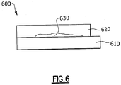
- Figure 6 illustrates two layers of a workpiece that includes a horizontal lack of fusion flaw.
- the workpiece 600 includes a first horizontal layer 610 and a second horizontal layer 620. Due to specific parameters during the manufacturing process, a portion of the top layer 620 is not fused to the bottom layer 610 due to the presence of unmelted material during the manufacturing process. This portion results in a horizontal lack of fusion flaw 630. The flaw, in turn, impacts the stability and structure of the part.
- flaws within a workpiece are the result of a combination of multiple parameters during the creation of the workpiece.
- the presence of unmelted material between one or more layers 610, 620 is primarily impacted by the power of the beam, the velocity of the beam, a local part temperature, a powder bed thickness, and a powder particle size.
- the power of the beam refers to the magnitude of power provided to the beam utilized to melt the particles forming the workpiece
- the velocity of the beam refers to the velocity at which the beam is moved across the powder bed in order to create the specific geometry of the workpiece.
- the local part temperature is the local temperature within the powder bed during the manufacturing process.
- the powder bed thickness is the depth of the powder bed during the manufacturing process.
- the powder particle size is the average size, including tolerances, of the particles within the powder utilized to create the workpiece.
- Each of the key parameters is represented as a bound, or multiple bounds defined using a function, or set of functions, as illustrated and described above with regards to Figures 3-5 .
- the specific functions can be determined according to known procedures and are specific to a given workpiece.
- the process can be applied in conjunction with a system and process for accounting for one or more additional flaws to further refine the operations for running the additive manufacturing process.
- the combination of the horizontal lack of fusion flaw validation and additional flaw validation can be achieved by providing a multidimensional space for each flaw, and iterating the validation process for each space.
- the bounds of each parameter for each of the multiple flaws can be merged into a single bound for the given parameter.
- a multidimensional space is then generated encompassing all of the parameters and the validation process can be run a single time.
- any of the above described concepts can be used alone or in combination with any or all of the other above described concepts.
- additional enumerated, or non-enumerated, parameters can impact the formation of any or all of the above described flaws.
- the above described system can be adapted to include additionally identified parameters, and still fall within the present disclosure.
Landscapes
- Engineering & Computer Science (AREA)
- Physics & Mathematics (AREA)
- Materials Engineering (AREA)
- Chemical & Material Sciences (AREA)
- Manufacturing & Machinery (AREA)
- Optics & Photonics (AREA)
- Geometry (AREA)
- General Physics & Mathematics (AREA)
- Mechanical Engineering (AREA)
- Theoretical Computer Science (AREA)
- Computational Mathematics (AREA)
- Mathematical Optimization (AREA)
- Pure & Applied Mathematics (AREA)
- Computer Hardware Design (AREA)
- Evolutionary Computation (AREA)
- General Engineering & Computer Science (AREA)
- Mathematical Analysis (AREA)
- Automation & Control Theory (AREA)
- Powder Metallurgy (AREA)
Abstract
Description
- The present disclosure relates generally to additive manufacturing, and more specifically to a process for evaluating and validating additive manufacturing operation sequences.
- Additive manufacturing is a process that is utilized to create components by applying sequential material layers, with each layer being applied to the previous material layer. As a result of the iterative, trial and error, construction process, multiple different parameters affect whether an end product created using the additive manufacturing process includes flaws, or is within acceptable tolerances of a given part. Typically, components created using an additive manufacturing process are designed iteratively, by adjusting one or more parameters each iteration and examining the results to determine if the results have the required quality.
- In some components, such as aircraft components, or other components with low tolerances, a substantial number of iterations can be required before determining a set of parameters that results in a component with an acceptable quality level. This iterative process can require months or years in order to refine a single part.
- In one aspect, a method of evaluating and validating additive manufacturing operations includes generating a multidimensional space defined by a plurality of bounds, each of the bounds being defined on a distinct parameter of an additive manufacturing process and each of the parameters being directly related to the occurrence of a horizontal lack of fusion flaw, each of the parameters being a dimension in a multi-dimensional coordinate system, determining a coordinate position of at least one additive manufacturing operation within the multi-dimensional coordinate system, and categorizing the operation as free of horizontal lack of fusion flaws when the coordinate position is within the multi-dimensional space.
- In an example of the above described exemplary method of evaluating and validating manufacturing operation an operation that is free of horizontal lack of fusion flaws is an additive manufacturing operation where horizontal lack of fusion flaws in a resultant work piece are below an acceptable threshold.
- In another example of any of the above described exemplary methods of evaluating and validating manufacturing operation the parameters include a beam power, a beam velocity, a local part temperature, a powder bed thickness, and a powder particle size, and wherein each of the bounds is defined by at least one mathematical function.
- In another example of any of the above described exemplary methods of evaluating and validating manufacturing operation each of the parameters is normalized to each other of the parameters.
- In another example of any of the above described exemplary methods of evaluating and validating manufacturing operation at least one of the mathematical functions is a least partially empirically determined.
- In another example of any of the above described exemplary methods of evaluating and validating manufacturing operation at least one of the mathematical functions is determined via simulation.
- Another example of any of the above described exemplary methods of evaluating and validating manufacturing operation further includes creating a work piece by causing an additive manufacturing machine to perform the at least one additive manufacturing operation in response to categorizing the at least one additive manufacturing operation as free of horizontal lack of fusion flaws.
- In another example of any of the above described exemplary methods of evaluating and validating manufacturing operation at least one of the parameters is partially unbounded.
- In another example of any of the above described exemplary methods of evaluating and validating manufacturing operation at least one of the parameters is fully bounded.
- In another example of any of the above described exemplary methods of evaluating and validating manufacturing operation the at least one additive manufacturing operation is a sequence of additive manufacturing operations.
- In another example of any of the above described exemplary methods of evaluating and validating manufacturing operation the sequence of additive manufacturing operations is an ordered list of all operations required to create a part.
- In another example of any of the above described exemplary methods of evaluating and validating manufacturing operation generating a multidimensional space defined by a plurality of bounds comprises generating multiple multidimensional spaces defined by a plurality of bounds, each of the multiple multidimensional spaces corresponding to one or more flaws and at least one of the multidimensional spaces corresponding to the horizontal lack of fusion flaw.
- The method according to the above aspect, or any embodiment thereof, may be performed on a processor, such as a processor of a controller, such as a controller of an additive manufacturing apparatus.
- In another aspect an additive manufacturing apparatus includes a chamber, a platform within the chamber, and a controller, the controlling including a processor and a memory, the memory storing instructions for causing the processor to validate at least one input operation as generating a workpiece free of horizontal lack of fusion flaws by determining a multi-dimensional coordinate in response to receiving the at least one input operation, and comparing the multi-dimensional coordinate to a stored multi-dimensional space, the stored multi-dimensional space being defined by a plurality of parameters including a beam power, a beam velocity, a local part temperature, a powder bed thickness, and a powder particle size.
- In an example of the above described additive manufacturing apparatus the chamber further includes a powder bed fusion apparatus.
- In another example of any of the above described additive manufacturing apparatus the powder bed fusion apparatus is a laser powder bed fusion apparatus.
- In another example of any of the above described additive manufacturing apparatus the powder bed fusion apparatus is an electron beam powder bed fusion apparatus.
- In another example of any of the above described additive manufacturing apparatus the memory further stores instructions for rejecting the at least one input operation in response to the determined multi-dimensional coordinate falling outside the multi-dimensional space.
- In another example of any of the above described additive manufacturing apparatus the multi-dimensional space is a space having four or more dimensions, and wherein each of the dimensions includes at least one bound corresponding to an operational parameter of an additive manufacturing process.
- The memory may store instructions for causing the processor to perform the method described above and claimed in claims 1 to 9.
- These and other features of the present invention can be best understood from the following specification and drawings, the following of which is a brief description.
-
-
Figure 1 schematically illustrates an exemplary additive manufacturing machine. -
Figure 2 illustrates an example method for evaluating and validating one or more additive manufacturing operations. -
Figures 3 illustrates an example parameter that defines a multi-dimensional space. -
Figure 4 illustrates another example parameter that defines the multi-dimensional space. -
Figure 5 illustrates another example parameter that defines the multi-dimensional space. -
Figure 6 illustrates one exemplary flaw that can be accounted for using the process and system described herein. -
Figure 1 schematically illustrates anadditive manufacturing machine 100, such as a laser powder bed fusion additive manufacturing machine. In alternate examples, the powder bed fusion machine can be an electron beam powder bed fusion machine. The exemplaryadditive manufacturing machine 100 includes amanufacturing chamber 110 with aplatform 120 upon which a part 130 (alternatively referred to as a work piece) is additively manufactured. Acontroller 140 is connected to thechamber 110 and controls the additive manufacturing process according to any known additive manufacturing control system. - Included within the
controller 140 is aprocessor 142 that receives and interprets input operations to define a sequence of the additive manufacturing. As utilized herein "operations" refers to instructions specifying operational conditions for one or more step in an additive manufacturing process. Thecontroller 140 can, in some examples, include user interface devices such as a keyboard and view screen. In alternative examples, thecontroller 140 can include a wireless or wired communication apparatus for communicating with a remote user input device such as a PC. - Also included in the
controller 140 is a memory 144. In some examples, thecontroller 140 receives a desired additive manufacturing operation, or sequence of operations, and evaluates the entered operation(s) to determine if theresultant part 130 will be free of flaws. For the purposes of the instant disclosure, free of flaws, or flaw free, refers to apart 130 or workpiece with no flaws causing the part or workpiece to fall outside of predefined tolerances. By way of example, the predefined tolerances can include an amount of unmelt, a surface roughness, or any other measurable parameter of thepart 130. Theprocessor 142 determines a set of parameters, based on the input operation(s) using a set of equations stored within the memory 144. Each of the equations is configured to determine a specific output parameter, based on two or more variables of the input operation(s). By way of example, factors impacting the output parameters can include material properties, environmental conditions, or any other factors. While described and illustrated herein as a component of a laser powder bed fusion additive manufacturing machine, the software configuration and operations can, in some examples, be embodied as a distinct software program independent of the additive manufacturing machine, or included within any other type of additive manufacturing machine. - The output parameters are combined to define a coordinate of the operation(s) on a multi-dimensional coordinate system. The multi-dimensional coordinate system is a coordinate system having more than three dimensions. The
processor 142 then compares the determined coordinate (the combined output parameter) against a multi-dimensional space defined in the multi-dimensional coordinate system, and stored in the memory 144. The multi-dimensional space is formed from one or more bounds within each dimension. If the coordinate falls within the multi-dimensional space, theprocessor 142 determines that the input operation(s) is flaw free. If the coordinate falls outside of the multi-dimensional space, theprocessor 142 determines that the input operation(s) will result in apart 130 or workpiece that is flawed, and prevents theadditive manufacturing machine 100 from creating thepart 130. In alternative examples, where the above described process is performed in a computer independent of theadditive manufacturing machine 100, the computer provides an output informing the operator if the input operation(s) will result in aflawed part 130. If the input operation(s) will not result in a flawed workpiece, the operation(s) can then be input in theadditive manufacturing machine 100, and thepart 130 is created. - By using the defined multi-dimensional space, a technician can generate a
part 130, or design a sequence of operations to generate apart 130, without requiring substantial empirical prototyping to be performed. This, in turn, allows the part to be designed faster, and with less expense, due to the substantially reduced number of physical iterations performed. - With continued reference to
Figure 1, Figure 2 illustrates anexample method 200 for evaluating and validating a manufacturing sequence of additive manufacturing operations. As described above, initially the technician inputs a desired operation, or sequence of operations, into the computer or the additive manufacturing machine at an "Input Operation(s)"step 210. - The computer/processor then calculates a number of parameters of the input operation(s), and assigns a coordinate in a multi-dimensional coordinate system based on the calculated parameters in a "Determine Coordinates of Operation(s)"
step 220. In some examples, the number of parameters, and thus the number of dimensions in the coordinate system, can be in excess of ten. In other examples, the number of parameters can exceed twenty. In an exemplary laser powder bed fusion additive manufacturing process, each of the parameters is determined by a mathematical function dependent on at least a power of a laser used and a scanning velocity of the laser. In alternative additive manufacturing systems, the parameters can be dependent upon other variables, such as a heat source power and a translation speed. - The parameters can include, but are not limited to, beam focus, wire or powder particle diameter, environmental conditions, particle density, or any number of other related parameters. Improper parameters can result in output parts including excessive flaws. The possible flaws impacted by the parameters include, but are not limited to, balling, keyholing, keyhole pore formation, lack of fusion, and unmelt. Alternative additive manufacturing systems can require, or use, alternative or additional parameters to define the multi-dimensional space depending on the specific features of the additive manufacturing system.
- In an exemplary laser powder bed fusion process, balling refers to the creation of spherical, or approximately spherical shapes within the structure of the part due to the specific operations. The balling flaw corresponds to an expected amount of balling within the
resultant part 130. Similarly, keyholing refers to the the creation of potentially unstable melt pool shapes during the manufacturing process, and the keyholing flaw corresponds to an expected amount of keyholing in the resultant part. Unmelt, refers to residual amounts of unmelted powder material within the part. - While the specifically enumerated parameters are parameters of a laser powder bed fusion additive manufacturing process, one of skill in the art having the benefit of this disclosure will understand that similar parameters related to any given additive manufacturing process could be utilized instead of, or in addition to, the enumerated parameters, and one of skill in the art, having the benefit of this disclosure, would be capable of ascertaining the relevant parameters for an alternative additive manufacturing system.
- Once the coordinate of the sequence of operations is determined, the computer/processor compares the coordinate to the predefined space in the multi-dimensional coordinate system in a "Compare Coordinates to Space"
step 230. As described above, the pre-defined space is a multi-dimensional space defining bounds along each dimension, with the dimensions corresponding to the parameters. If the determined coordinate of the sequence of operations is within the space, the computer/processor validates the sequence of operations as flaw free in a "Validate Operation(s) as flaw free" step 240. If, however, the coordinate falls outside of the predefined space, the computer/processor rejects the sequence of operation as being flawed, or resulting in a flawed part, in a "Reject Operation as Producing Flaws"step 250. - The rejection of an input sequence as resulting in a flawed part can take the form of the controller of an additive manufacturing system, such as a laser powder bed fusion additive manufacturing system, rejecting the sequence of operations. In alternative examples, where the process is performed on a computer, the rejection of the input sequence of operations as resulting in a flawed part can take the form of a warning, or other prompt, informing the user that the proposed sequence of operations is flawed.
- By utilizing the predefined space, a technician can attempt several sequences of operations for making a given part without being required to iterate multiple physical prototypes. One of skill in the art will recognize, however, that the result of an operation may still include unanticipated flaws, or be otherwise unsuitable even if the above process validates it. As such, in some examples, a minimal amount of iteration is still required to develop an acceptable end part. In such an example, each iteration of the sequence of operations is compared to the space and subjected to the evaluation and validation process. Further, the equations defining the bounds of each dimension of the multi-dimensional space can be refined, in light of the new empirical data, between iterations to account for the newly determined flawed coordinate. This refinement can be carried forward and applied to validation of further sequences of operations, or limited to the current input sequence of operations, depending on the nature of the parameter being refined. By way of example, if the parameter being refined is related to powder particle size, the parameter could be applied forward. However, if the parameter is related to the specific environmental conditions, such as an ambient humidity, the parameter would not be universally applicable, and may be limited to the instant validation.
- With continued reference to
Figures 1 and 2 above,Figures 3-5 illustrate example parameters that define dimensions and bounds of the multi-dimensional space discussed above. With regards toFigure 3 , a polynomial bound is defined and is dependent upon a beam power (P) and a scanning velocity (V) of a laser in a laser powder bed fusion additive manufacturing system. The example ofFigure 3 defines a bound 330 relative to a beam power (P)axis 310 and a scanning velocity axis (v). In the illustrated bound 330, everything on one side of the bound 330 defines a "flaw free"region 340, whereas everything on the other side of the bound 330 is known to produce unacceptable levels of flaws. -
Figure 4 illustrates a bound 430 that has a linear relationship between a beam power (P)axis 410 and a scanning velocity (V)axis 420. As with the example ofFigure 3 , everything on one side the bound 430 is a "flaw free"region 540, while everything on the other side of the bound 430 is known to include unacceptable levels of flaws. -
Figure 5 illustrates a bound defined by twofunctions functions region 540 and everything not between the two thefunctions - Each of the plots of
Figures 3-5 corresponds to one parameter, and one dimension of the multi-dimensional space. The specific equations defining the bounds within each parameter can be developed by one of skill in the art, and are dependent on the specific part being constructed, and the corresponding tolerances of that part. The bounds and parameters are further dependent on the additive manufacturing process, the type of additive manufacturing machine being utilized and any number of other factors. - Each of the examples of
Figures 3, 4 and 5 illustrates a partially unbounded parameter which defines a flawfree region - To define the multi-dimensional space discussed above, each of the parameters of
Figures 3, 4 and 5 are combined in a single coordinate system, with each parameter being a unique dimension. To facilitate the combination, the parameters are normalized to a single scale. The flawfree regions - In some examples, the bounds of each parameter are determined empirically, via iterative testing in a laboratory environment. In other examples, the bounds of each parameter are determined via mathematical modeling and simulations, and no iterations or physical tests are required. Even further still, in some embodiments, the bounds of the parameters are developed as a combination of both physical testing and theoretical models with some parameters being based on empirical data and some parameters being determined by theoretical modeling.
- One of skill in the art, having the benefit of this disclosure will further understand that the multi-dimensional space can be utilized in the reverse manner to determine appropriate parameters to create a given work piece. In such an example, the parameter coordinates for a given operation are entered into the computer/processer, and the computer/processor reverses the steps to determine an operation, or sequence of operations, that result in the desired parameter coordinates.
- In one specific example, the system described above can account for, and prevent, operations that will result in a horizontal lack of fusion flow. A horizontal lack of fusion refers to a component where a first layer of the additively manufactured part is not connected to (alternately referred to as fused to) one of the adjacent layers of the additively manufactured part. As used herein, "horizontal" refers to a horizontal orientation of the workpiece, relative to gravity, as the workpiece is being created.
- With continued reference to
Figures 1-5 ,Figure 6 illustrates two layers of a workpiece that includes a horizontal lack of fusion flaw. Theworkpiece 600 includes a firsthorizontal layer 610 and a secondhorizontal layer 620. Due to specific parameters during the manufacturing process, a portion of thetop layer 620 is not fused to thebottom layer 610 due to the presence of unmelted material during the manufacturing process. This portion results in a horizontal lack offusion flaw 630. The flaw, in turn, impacts the stability and structure of the part. - As described above, flaws within a workpiece are the result of a combination of multiple parameters during the creation of the workpiece. The presence of unmelted material between one or
more layers - The power of the beam refers to the magnitude of power provided to the beam utilized to melt the particles forming the workpiece, and the velocity of the beam refers to the velocity at which the beam is moved across the powder bed in order to create the specific geometry of the workpiece. The local part temperature is the local temperature within the powder bed during the manufacturing process. The powder bed thickness is the depth of the powder bed during the manufacturing process. The powder particle size is the average size, including tolerances, of the particles within the powder utilized to create the workpiece.
- Each of the key parameters is represented as a bound, or multiple bounds defined using a function, or set of functions, as illustrated and described above with regards to
Figures 3-5 . The specific functions can be determined according to known procedures and are specific to a given workpiece. - While a process and system for accounting for horizontal lack of fusion is described herein, one of skill in the art will understand that the process can be applied in conjunction with a system and process for accounting for one or more additional flaws to further refine the operations for running the additive manufacturing process. In some examples, the combination of the horizontal lack of fusion flaw validation and additional flaw validation can be achieved by providing a multidimensional space for each flaw, and iterating the validation process for each space. In alternative examples, the bounds of each parameter for each of the multiple flaws can be merged into a single bound for the given parameter. A multidimensional space is then generated encompassing all of the parameters and the validation process can be run a single time.
- It is further understood that any of the above described concepts can be used alone or in combination with any or all of the other above described concepts. Further, one of skill in the art having the benefit of this disclosure will understand that additional enumerated, or non-enumerated, parameters can impact the formation of any or all of the above described flaws. As such, the above described system can be adapted to include additionally identified parameters, and still fall within the present disclosure. Although an embodiment of this invention has been disclosed, a worker of ordinary skill in this art would recognize that certain modifications would come within the scope of this invention. For that reason, the following claims should be studied to determine the true scope and content of this invention.
Claims (15)
- A method of evaluating and validating additive manufacturing operations comprising:generating a multidimensional space (340; 440; 540) defined by a plurality of bounds (330; 430; 530, 550), each of said bounds (330...550) being defined on a distinct parameter of an additive manufacturing process and each of said parameters being directly related to the occurrence of a horizontal lack of fusion flaw (630), each of said parameters being a dimension in a multi-dimensional coordinate system;determining a coordinate position of at least one additive manufacturing operation within the multi-dimensional coordinate system; andcategorizing the operation as free of horizontal lack of fusion flaws (630) when the coordinate position is within the multi-dimensional space (340; 440; 540).
- The method of claim 1, wherein an operation that is free of horizontal lack of fusion flaws (630) is an additive manufacturing operation where horizontal lack of fusion flaws (630) in a resultant work piece (600) are below an acceptable threshold.
- The method of claim 1 or 2, wherein the parameters include a beam power, a beam velocity, a local part temperature, a powder bed thickness, and a powder particle size, and wherein each of the bounds (330...550) is defined by at least one mathematical function.
- The method of claim 3, wherein:each of said parameters is normalized to each other of said parameters;at least one of the mathematical functions is a least partially empirically determined; and/orat least one of the mathematical functions is determined via simulation.
- The method of any preceding claim, further comprising creating a work piece (600) by causing an additive manufacturing machine (100) to perform the at least one additive manufacturing operation in response to categorizing the at least one additive manufacturing operation as free of horizontal lack of fusion flaws (630).
- The method of any preceding claim, wherein at least one of the parameters is partially unbounded.
- The method of any preceding claim, wherein at least one of the parameters is fully bounded.
- The method of any preceding claim, wherein the at least one additive manufacturing operation is a sequence of additive manufacturing operations, optionally wherein the sequence of additive manufacturing operations is an ordered list of all operations required to create a part.
- The method of any preceding claim, wherein generating a multidimensional space (340; 440; 540) defined by a plurality of bounds (330...550) comprises generating multiple multidimensional spaces (340; 440; 540) defined by a plurality of bounds (330...550), each of said multiple multidimensional spaces (330...550) corresponding to one or more flaws and at least one of said multidimensional spaces (330...550) corresponding to the horizontal lack of fusion flaw (630).
- An additive manufacturing apparatus (100) comprising:a chamber (110);a platform (120) within said chamber (110); anda controller (140), the controller including a processor (142) and a memory (144), the memory (144) storing instructions for causing the processor (142) to validate at least one input operation as generating a workpiece (600) free of horizontal lack of fusion flaws (630) by determining a multi-dimensional coordinate in response to receiving the at least one input operation, and comparing the multi-dimensional coordinate to a stored multi-dimensional space (340; 440; 540), the stored multi-dimensional space being defined by a plurality of parameters including a beam power, a beam velocity, a local part temperature, a powder bed thickness, and a powder particle size.
- The additive manufacturing apparatus (100) of claim 10, wherein the chamber (110) further includes a powder bed fusion apparatus.
- The additive manufacturing apparatus (100) of claim 11, wherein the powder bed fusion apparatus is a laser powder bed fusion apparatus.
- The additive manufacturing apparatus (100) of claim 11, wherein the powder bed fusion apparatus is an electron beam powder bed fusion apparatus.
- The additive manufacturing apparatus (100) of any of claims 10 to 13, wherein the memory (144) further stores instructions for rejecting the at least one input operation in response to the determined multi-dimensional coordinate falling outside the multi-dimensional space (340; 440; 540).
- The additive manufacturing apparatus (100) of any of claims 10 to 14, wherein the multi-dimensional space (340; 440; 540) is a space having four or more dimensions, and wherein each of said dimensions includes at least one bound (330...550) corresponding to an operational parameter of an additive manufacturing process.
Applications Claiming Priority (2)
| Application Number | Priority Date | Filing Date | Title |
|---|---|---|---|
| US201662321328P | 2016-04-12 | 2016-04-12 | |
| US15/441,620 US10254730B2 (en) | 2016-04-12 | 2017-02-24 | System and process for evaluating and validating additive manufacturing operations |
Publications (2)
| Publication Number | Publication Date |
|---|---|
| EP3232351A1 true EP3232351A1 (en) | 2017-10-18 |
| EP3232351B1 EP3232351B1 (en) | 2022-02-02 |
Family
ID=58536880
Family Applications (1)
| Application Number | Title | Priority Date | Filing Date |
|---|---|---|---|
| EP17166007.9A Active EP3232351B1 (en) | 2016-04-12 | 2017-04-11 | System and process for evaluating and validating additive manufacturing operations |
Country Status (2)
| Country | Link |
|---|---|
| US (1) | US10254730B2 (en) |
| EP (1) | EP3232351B1 (en) |
Cited By (4)
| Publication number | Priority date | Publication date | Assignee | Title |
|---|---|---|---|---|
| CN111112621A (en) * | 2020-01-22 | 2020-05-08 | 南京理工大学 | A method for predicting and monitoring the shape and size of the molten pool for laser directed energy deposition |
| CN111169016A (en) * | 2019-12-18 | 2020-05-19 | 西北工业大学 | 3+2 axis unsupported 3D printing manufacturing method of blade parts |
| WO2020247544A1 (en) * | 2019-06-07 | 2020-12-10 | Materialise N.V. | Systems and methods for selection of processing parameter for additive manufacturing using simulation |
| WO2024134666A1 (en) * | 2022-12-23 | 2024-06-27 | Indian Institute Of Science | System and process for additive fabrication and manufacturing |
Families Citing this family (3)
| Publication number | Priority date | Publication date | Assignee | Title |
|---|---|---|---|---|
| DE102019109655B4 (en) * | 2019-04-11 | 2025-10-16 | Schubert Additive Solutions GmbH | Method and system for additive manufacturing of at least one component with defined component properties |
| US11531920B2 (en) | 2020-04-27 | 2022-12-20 | Raytheon Technologies Corporation | System and process for verifying powder bed fusion additive manufacturing operation as being defect free |
| US12023103B2 (en) * | 2022-08-25 | 2024-07-02 | Ix Innovation Llc | 3D printing of structures inside a patient |
Citations (1)
| Publication number | Priority date | Publication date | Assignee | Title |
|---|---|---|---|---|
| DE102015011013A1 (en) * | 2014-08-22 | 2016-02-25 | Sigma Labs, Inc. | Method and system for monitoring generative manufacturing processes |
Family Cites Families (7)
| Publication number | Priority date | Publication date | Assignee | Title |
|---|---|---|---|---|
| US6813533B1 (en) | 2001-05-15 | 2004-11-02 | Vladimir V. Semak | Method for simulation of laser material deposition |
| US20080223832A1 (en) | 2006-11-16 | 2008-09-18 | Lijun Song | Real time implementation of generalized predictive control algorithm for the control of direct metal deposition (dmd) process |
| US9044827B2 (en) | 2007-05-31 | 2015-06-02 | Dm3D Technology, Llc | Real-time implementation of generalized predictive algorithm for direct metal deposition (DMD) process control |
| DE102011003314A1 (en) | 2011-01-28 | 2012-08-02 | Airbus Operations Gmbh | Method for producing a component |
| US9933255B2 (en) | 2011-07-29 | 2018-04-03 | Carnegie Mellon University | Process mapping of melt pool geometry |
| US9724876B2 (en) * | 2013-12-13 | 2017-08-08 | General Electric Company | Operational performance assessment of additive manufacturing |
| US9573224B2 (en) | 2014-09-02 | 2017-02-21 | Product Innovation & Engineering, LLC | System and method for determining beam power level along an additive deposition path |
-
2017
- 2017-02-24 US US15/441,620 patent/US10254730B2/en active Active
- 2017-04-11 EP EP17166007.9A patent/EP3232351B1/en active Active
Patent Citations (2)
| Publication number | Priority date | Publication date | Assignee | Title |
|---|---|---|---|---|
| DE102015011013A1 (en) * | 2014-08-22 | 2016-02-25 | Sigma Labs, Inc. | Method and system for monitoring generative manufacturing processes |
| US20160184893A1 (en) * | 2014-08-22 | 2016-06-30 | Sigma Labs, Inc. | Method and system for monitoring additive manufacturing processes |
Non-Patent Citations (3)
| Title |
|---|
| KAMATH CHANDRIKA: "Data mining and statistical inference in selective laser melting", INTERNATIONAL JOURNAL OF ADVANCED MANUFACTURING TECHNOLOGY, SPRINGER VERLAG, LONDON; GB, vol. 86, no. 5, 11 January 2016 (2016-01-11), pages 1659 - 1677, XP036058635, ISSN: 0268-3768, [retrieved on 20160111], DOI: 10.1007/S00170-015-8289-2 * |
| M L VLASEA ET AL: "DEVELOPMENT OF POWDER BED FUSION ADDITIVE MANUFACTURING TEST BED FOR ENHANCED REAL-TIME PROCESS CONTROL", 31 December 2015 (2015-12-31), XP055312433, Retrieved from the Internet <URL:http://sffsymposium.engr.utexas.edu/sites/default/files/2015/2015-42-Vlasea.pdf> [retrieved on 20161019] * |
| W. J. SAMES ET AL: "The metallurgy and processing science of metal additive manufacturing", INTERNATIONAL MATERIALS REVIEWS, vol. 61, no. 5, 7 March 2016 (2016-03-07), US, pages 315 - 360, XP055398013, ISSN: 0950-6608, DOI: 10.1080/09506608.2015.1116649 * |
Cited By (5)
| Publication number | Priority date | Publication date | Assignee | Title |
|---|---|---|---|---|
| WO2020247544A1 (en) * | 2019-06-07 | 2020-12-10 | Materialise N.V. | Systems and methods for selection of processing parameter for additive manufacturing using simulation |
| CN111169016A (en) * | 2019-12-18 | 2020-05-19 | 西北工业大学 | 3+2 axis unsupported 3D printing manufacturing method of blade parts |
| CN111169016B (en) * | 2019-12-18 | 2021-11-16 | 西北工业大学 | 3+2 shaft unsupported 3D printing manufacturing method for blade parts |
| CN111112621A (en) * | 2020-01-22 | 2020-05-08 | 南京理工大学 | A method for predicting and monitoring the shape and size of the molten pool for laser directed energy deposition |
| WO2024134666A1 (en) * | 2022-12-23 | 2024-06-27 | Indian Institute Of Science | System and process for additive fabrication and manufacturing |
Also Published As
| Publication number | Publication date |
|---|---|
| EP3232351B1 (en) | 2022-02-02 |
| US10254730B2 (en) | 2019-04-09 |
| US20170291366A1 (en) | 2017-10-12 |
Similar Documents
| Publication | Publication Date | Title |
|---|---|---|
| EP3232353B1 (en) | System and process for evaluating and validating additive manufacturing operations | |
| EP3232351B1 (en) | System and process for evaluating and validating additive manufacturing operations | |
| US10252512B2 (en) | System and process for evaluating and validating additive manufacturing operations | |
| CN110023057B (en) | Energy density mapping in an additive manufacturing environment | |
| JP6557355B2 (en) | Method for producing three-dimensional shaped member | |
| US20200156323A1 (en) | Systems and methods for optimization of design and tool paths for additive manufacturing | |
| CN113840675B (en) | In-situ monitoring system auxiliary material and parameter development for additive manufacturing | |
| CN110366463B (en) | System and method for controlling microstructure of additively manufactured component | |
| CN113196186A (en) | Automatic parameterization of laser cutting method | |
| US11073824B1 (en) | System and method of simulating and optimizing surface quality based on location and orientation of additively manufactured build parts | |
| US11733678B2 (en) | Method for determining building instructions for an additive manufacturing method, method for generating a database with correction measures for controlling the process of an additive manufacturing method | |
| CN103894807A (en) | Method and device for reducing potential injury to operators | |
| US11609549B2 (en) | Transfer learning/dictionary generation and usage for tailored part parameter generation from coupon builds | |
| US10252510B2 (en) | System and process for evaluating and validating additive manufacturing operations | |
| US10252511B2 (en) | System and process for evaluating and validating additive manufacturing operations | |
| US10252508B2 (en) | System and process for evaluating and validating additive manufacturing operations | |
| JP7651214B2 (en) | Method for developing additive manufacturing technology and 3D additive manufacturing system | |
| EP4587258A1 (en) | Machine learning based rapid parameter development for additive manufacturing and related methods | |
| US20240393765A1 (en) | Predictive model for multi-laser powder bed fusion additive manufacturing | |
| Rosen | Process control and metrics |
Legal Events
| Date | Code | Title | Description |
|---|---|---|---|
| PUAI | Public reference made under article 153(3) epc to a published international application that has entered the european phase |
Free format text: ORIGINAL CODE: 0009012 |
|
| STAA | Information on the status of an ep patent application or granted ep patent |
Free format text: STATUS: THE APPLICATION HAS BEEN PUBLISHED |
|
| AK | Designated contracting states |
Kind code of ref document: A1 Designated state(s): AL AT BE BG CH CY CZ DE DK EE ES FI FR GB GR HR HU IE IS IT LI LT LU LV MC MK MT NL NO PL PT RO RS SE SI SK SM TR |
|
| AX | Request for extension of the european patent |
Extension state: BA ME |
|
| STAA | Information on the status of an ep patent application or granted ep patent |
Free format text: STATUS: REQUEST FOR EXAMINATION WAS MADE |
|
| 17P | Request for examination filed |
Effective date: 20180418 |
|
| RBV | Designated contracting states (corrected) |
Designated state(s): AL AT BE BG CH CY CZ DE DK EE ES FI FR GB GR HR HU IE IS IT LI LT LU LV MC MK MT NL NO PL PT RO RS SE SI SK SM TR |
|
| REG | Reference to a national code |
Ref country code: DE Ref legal event code: R079 Ref document number: 602017052983 Country of ref document: DE Free format text: PREVIOUS MAIN CLASS: G06F0017500000 Ipc: B22F0010100000 |
|
| GRAP | Despatch of communication of intention to grant a patent |
Free format text: ORIGINAL CODE: EPIDOSNIGR1 |
|
| RIC1 | Information provided on ipc code assigned before grant |
Ipc: B29C 64/153 20170101ALI20210204BHEP Ipc: B22F 10/10 20210101AFI20210204BHEP Ipc: B22F 3/105 20060101ALI20210204BHEP Ipc: B29C 67/00 20170101ALI20210204BHEP Ipc: B29C 64/393 20170101ALI20210204BHEP Ipc: B33Y 50/02 20150101ALI20210204BHEP Ipc: G06F 119/18 20200101ALI20210204BHEP Ipc: G06F 30/17 20200101ALI20210204BHEP |
|
| STAA | Information on the status of an ep patent application or granted ep patent |
Free format text: STATUS: GRANT OF PATENT IS INTENDED |
|
| INTG | Intention to grant announced |
Effective date: 20210311 |
|
| GRAJ | Information related to disapproval of communication of intention to grant by the applicant or resumption of examination proceedings by the epo deleted |
Free format text: ORIGINAL CODE: EPIDOSDIGR1 |
|
| STAA | Information on the status of an ep patent application or granted ep patent |
Free format text: STATUS: REQUEST FOR EXAMINATION WAS MADE |
|
| GRAP | Despatch of communication of intention to grant a patent |
Free format text: ORIGINAL CODE: EPIDOSNIGR1 |
|
| STAA | Information on the status of an ep patent application or granted ep patent |
Free format text: STATUS: GRANT OF PATENT IS INTENDED |
|
| INTC | Intention to grant announced (deleted) | ||
| INTG | Intention to grant announced |
Effective date: 20210817 |
|
| GRAS | Grant fee paid |
Free format text: ORIGINAL CODE: EPIDOSNIGR3 |
|
| GRAA | (expected) grant |
Free format text: ORIGINAL CODE: 0009210 |
|
| STAA | Information on the status of an ep patent application or granted ep patent |
Free format text: STATUS: THE PATENT HAS BEEN GRANTED |
|
| RAP3 | Party data changed (applicant data changed or rights of an application transferred) |
Owner name: UNITED TECHNOLOGIES CORPORATION |
|
| RIN1 | Information on inventor provided before grant (corrected) |
Inventor name: FURRER, DAVID ULRICH Inventor name: BRINDLEY, WILLIAM J. Inventor name: NOVIKOV, DMITRI Inventor name: BURLATSKY, SERGEI F. |
|
| RAP3 | Party data changed (applicant data changed or rights of an application transferred) |
Owner name: RAYTHEON TECHNOLOGIES CORPORATION |
|
| AK | Designated contracting states |
Kind code of ref document: B1 Designated state(s): AL AT BE BG CH CY CZ DE DK EE ES FI FR GB GR HR HU IE IS IT LI LT LU LV MC MK MT NL NO PL PT RO RS SE SI SK SM TR |
|
| REG | Reference to a national code |
Ref country code: GB Ref legal event code: FG4D |
|
| REG | Reference to a national code |
Ref country code: CH Ref legal event code: EP Ref country code: AT Ref legal event code: REF Ref document number: 1466454 Country of ref document: AT Kind code of ref document: T Effective date: 20220215 |
|
| REG | Reference to a national code |
Ref country code: DE Ref legal event code: R096 Ref document number: 602017052983 Country of ref document: DE |
|
| REG | Reference to a national code |
Ref country code: IE Ref legal event code: FG4D |
|
| REG | Reference to a national code |
Ref country code: LT Ref legal event code: MG9D |
|
| REG | Reference to a national code |
Ref country code: NL Ref legal event code: MP Effective date: 20220202 |
|
| REG | Reference to a national code |
Ref country code: AT Ref legal event code: MK05 Ref document number: 1466454 Country of ref document: AT Kind code of ref document: T Effective date: 20220202 |
|
| PG25 | Lapsed in a contracting state [announced via postgrant information from national office to epo] |
Ref country code: SE Free format text: LAPSE BECAUSE OF FAILURE TO SUBMIT A TRANSLATION OF THE DESCRIPTION OR TO PAY THE FEE WITHIN THE PRESCRIBED TIME-LIMIT Effective date: 20220202 Ref country code: RS Free format text: LAPSE BECAUSE OF FAILURE TO SUBMIT A TRANSLATION OF THE DESCRIPTION OR TO PAY THE FEE WITHIN THE PRESCRIBED TIME-LIMIT Effective date: 20220202 Ref country code: PT Free format text: LAPSE BECAUSE OF FAILURE TO SUBMIT A TRANSLATION OF THE DESCRIPTION OR TO PAY THE FEE WITHIN THE PRESCRIBED TIME-LIMIT Effective date: 20220602 Ref country code: NO Free format text: LAPSE BECAUSE OF FAILURE TO SUBMIT A TRANSLATION OF THE DESCRIPTION OR TO PAY THE FEE WITHIN THE PRESCRIBED TIME-LIMIT Effective date: 20220502 Ref country code: NL Free format text: LAPSE BECAUSE OF FAILURE TO SUBMIT A TRANSLATION OF THE DESCRIPTION OR TO PAY THE FEE WITHIN THE PRESCRIBED TIME-LIMIT Effective date: 20220202 Ref country code: LT Free format text: LAPSE BECAUSE OF FAILURE TO SUBMIT A TRANSLATION OF THE DESCRIPTION OR TO PAY THE FEE WITHIN THE PRESCRIBED TIME-LIMIT Effective date: 20220202 Ref country code: HR Free format text: LAPSE BECAUSE OF FAILURE TO SUBMIT A TRANSLATION OF THE DESCRIPTION OR TO PAY THE FEE WITHIN THE PRESCRIBED TIME-LIMIT Effective date: 20220202 Ref country code: ES Free format text: LAPSE BECAUSE OF FAILURE TO SUBMIT A TRANSLATION OF THE DESCRIPTION OR TO PAY THE FEE WITHIN THE PRESCRIBED TIME-LIMIT Effective date: 20220202 Ref country code: BG Free format text: LAPSE BECAUSE OF FAILURE TO SUBMIT A TRANSLATION OF THE DESCRIPTION OR TO PAY THE FEE WITHIN THE PRESCRIBED TIME-LIMIT Effective date: 20220502 |
|
| PG25 | Lapsed in a contracting state [announced via postgrant information from national office to epo] |
Ref country code: PL Free format text: LAPSE BECAUSE OF FAILURE TO SUBMIT A TRANSLATION OF THE DESCRIPTION OR TO PAY THE FEE WITHIN THE PRESCRIBED TIME-LIMIT Effective date: 20220202 Ref country code: LV Free format text: LAPSE BECAUSE OF FAILURE TO SUBMIT A TRANSLATION OF THE DESCRIPTION OR TO PAY THE FEE WITHIN THE PRESCRIBED TIME-LIMIT Effective date: 20220202 Ref country code: GR Free format text: LAPSE BECAUSE OF FAILURE TO SUBMIT A TRANSLATION OF THE DESCRIPTION OR TO PAY THE FEE WITHIN THE PRESCRIBED TIME-LIMIT Effective date: 20220503 Ref country code: FI Free format text: LAPSE BECAUSE OF FAILURE TO SUBMIT A TRANSLATION OF THE DESCRIPTION OR TO PAY THE FEE WITHIN THE PRESCRIBED TIME-LIMIT Effective date: 20220202 Ref country code: AT Free format text: LAPSE BECAUSE OF FAILURE TO SUBMIT A TRANSLATION OF THE DESCRIPTION OR TO PAY THE FEE WITHIN THE PRESCRIBED TIME-LIMIT Effective date: 20220202 |
|
| PG25 | Lapsed in a contracting state [announced via postgrant information from national office to epo] |
Ref country code: IS Free format text: LAPSE BECAUSE OF FAILURE TO SUBMIT A TRANSLATION OF THE DESCRIPTION OR TO PAY THE FEE WITHIN THE PRESCRIBED TIME-LIMIT Effective date: 20220602 |
|
| PG25 | Lapsed in a contracting state [announced via postgrant information from national office to epo] |
Ref country code: SM Free format text: LAPSE BECAUSE OF FAILURE TO SUBMIT A TRANSLATION OF THE DESCRIPTION OR TO PAY THE FEE WITHIN THE PRESCRIBED TIME-LIMIT Effective date: 20220202 Ref country code: SK Free format text: LAPSE BECAUSE OF FAILURE TO SUBMIT A TRANSLATION OF THE DESCRIPTION OR TO PAY THE FEE WITHIN THE PRESCRIBED TIME-LIMIT Effective date: 20220202 Ref country code: RO Free format text: LAPSE BECAUSE OF FAILURE TO SUBMIT A TRANSLATION OF THE DESCRIPTION OR TO PAY THE FEE WITHIN THE PRESCRIBED TIME-LIMIT Effective date: 20220202 Ref country code: EE Free format text: LAPSE BECAUSE OF FAILURE TO SUBMIT A TRANSLATION OF THE DESCRIPTION OR TO PAY THE FEE WITHIN THE PRESCRIBED TIME-LIMIT Effective date: 20220202 Ref country code: DK Free format text: LAPSE BECAUSE OF FAILURE TO SUBMIT A TRANSLATION OF THE DESCRIPTION OR TO PAY THE FEE WITHIN THE PRESCRIBED TIME-LIMIT Effective date: 20220202 Ref country code: CZ Free format text: LAPSE BECAUSE OF FAILURE TO SUBMIT A TRANSLATION OF THE DESCRIPTION OR TO PAY THE FEE WITHIN THE PRESCRIBED TIME-LIMIT Effective date: 20220202 |
|
| REG | Reference to a national code |
Ref country code: DE Ref legal event code: R097 Ref document number: 602017052983 Country of ref document: DE |
|
| PG25 | Lapsed in a contracting state [announced via postgrant information from national office to epo] |
Ref country code: AL Free format text: LAPSE BECAUSE OF FAILURE TO SUBMIT A TRANSLATION OF THE DESCRIPTION OR TO PAY THE FEE WITHIN THE PRESCRIBED TIME-LIMIT Effective date: 20220202 |
|
| REG | Reference to a national code |
Ref country code: CH Ref legal event code: PL |
|
| PLBE | No opposition filed within time limit |
Free format text: ORIGINAL CODE: 0009261 |
|
| STAA | Information on the status of an ep patent application or granted ep patent |
Free format text: STATUS: NO OPPOSITION FILED WITHIN TIME LIMIT |
|
| REG | Reference to a national code |
Ref country code: BE Ref legal event code: MM Effective date: 20220430 |
|
| 26N | No opposition filed |
Effective date: 20221103 |
|
| PG25 | Lapsed in a contracting state [announced via postgrant information from national office to epo] |
Ref country code: MC Free format text: LAPSE BECAUSE OF FAILURE TO SUBMIT A TRANSLATION OF THE DESCRIPTION OR TO PAY THE FEE WITHIN THE PRESCRIBED TIME-LIMIT Effective date: 20220202 Ref country code: LU Free format text: LAPSE BECAUSE OF NON-PAYMENT OF DUE FEES Effective date: 20220411 Ref country code: LI Free format text: LAPSE BECAUSE OF NON-PAYMENT OF DUE FEES Effective date: 20220430 Ref country code: CH Free format text: LAPSE BECAUSE OF NON-PAYMENT OF DUE FEES Effective date: 20220430 |
|
| PG25 | Lapsed in a contracting state [announced via postgrant information from national office to epo] |
Ref country code: SI Free format text: LAPSE BECAUSE OF FAILURE TO SUBMIT A TRANSLATION OF THE DESCRIPTION OR TO PAY THE FEE WITHIN THE PRESCRIBED TIME-LIMIT Effective date: 20220202 Ref country code: BE Free format text: LAPSE BECAUSE OF NON-PAYMENT OF DUE FEES Effective date: 20220430 |
|
| PG25 | Lapsed in a contracting state [announced via postgrant information from national office to epo] |
Ref country code: IE Free format text: LAPSE BECAUSE OF NON-PAYMENT OF DUE FEES Effective date: 20220411 |
|
| P01 | Opt-out of the competence of the unified patent court (upc) registered |
Effective date: 20230521 |
|
| PG25 | Lapsed in a contracting state [announced via postgrant information from national office to epo] |
Ref country code: IT Free format text: LAPSE BECAUSE OF FAILURE TO SUBMIT A TRANSLATION OF THE DESCRIPTION OR TO PAY THE FEE WITHIN THE PRESCRIBED TIME-LIMIT Effective date: 20220202 |
|
| PG25 | Lapsed in a contracting state [announced via postgrant information from national office to epo] |
Ref country code: HU Free format text: LAPSE BECAUSE OF FAILURE TO SUBMIT A TRANSLATION OF THE DESCRIPTION OR TO PAY THE FEE WITHIN THE PRESCRIBED TIME-LIMIT; INVALID AB INITIO Effective date: 20170411 |
|
| PG25 | Lapsed in a contracting state [announced via postgrant information from national office to epo] |
Ref country code: MK Free format text: LAPSE BECAUSE OF FAILURE TO SUBMIT A TRANSLATION OF THE DESCRIPTION OR TO PAY THE FEE WITHIN THE PRESCRIBED TIME-LIMIT Effective date: 20220202 Ref country code: CY Free format text: LAPSE BECAUSE OF FAILURE TO SUBMIT A TRANSLATION OF THE DESCRIPTION OR TO PAY THE FEE WITHIN THE PRESCRIBED TIME-LIMIT Effective date: 20220202 |
|
| PG25 | Lapsed in a contracting state [announced via postgrant information from national office to epo] |
Ref country code: TR Free format text: LAPSE BECAUSE OF FAILURE TO SUBMIT A TRANSLATION OF THE DESCRIPTION OR TO PAY THE FEE WITHIN THE PRESCRIBED TIME-LIMIT Effective date: 20220202 |
|
| PG25 | Lapsed in a contracting state [announced via postgrant information from national office to epo] |
Ref country code: MT Free format text: LAPSE BECAUSE OF FAILURE TO SUBMIT A TRANSLATION OF THE DESCRIPTION OR TO PAY THE FEE WITHIN THE PRESCRIBED TIME-LIMIT Effective date: 20220202 |
|
| PGFP | Annual fee paid to national office [announced via postgrant information from national office to epo] |
Ref country code: DE Payment date: 20250319 Year of fee payment: 9 |
|
| REG | Reference to a national code |
Ref country code: DE Ref legal event code: R081 Ref document number: 602017052983 Country of ref document: DE Owner name: RTX CORPORATION (N.D.GES.D. STAATES DELAWARE),, US Free format text: FORMER OWNER: RAYTHEON TECHNOLOGIES CORPORATION, FARMINGTON, CT, US |
|
| PGFP | Annual fee paid to national office [announced via postgrant information from national office to epo] |
Ref country code: GB Payment date: 20260319 Year of fee payment: 10 |
|
| PGFP | Annual fee paid to national office [announced via postgrant information from national office to epo] |
Ref country code: FR Payment date: 20260319 Year of fee payment: 10 |