EP3232283A1 - Flow sensor bit for motor driven compressor - Google Patents
Flow sensor bit for motor driven compressor Download PDFInfo
- Publication number
- EP3232283A1 EP3232283A1 EP17166209.1A EP17166209A EP3232283A1 EP 3232283 A1 EP3232283 A1 EP 3232283A1 EP 17166209 A EP17166209 A EP 17166209A EP 3232283 A1 EP3232283 A1 EP 3232283A1
- Authority
- EP
- European Patent Office
- Prior art keywords
- input
- airflow
- compressor
- temperature
- estimated
- Prior art date
- Legal status (The legal status is an assumption and is not a legal conclusion. Google has not performed a legal analysis and makes no representation as to the accuracy of the status listed.)
- Granted
Links
Images

Classifications
-
- G—PHYSICS
- G01—MEASURING; TESTING
- G01F—MEASURING VOLUME, VOLUME FLOW, MASS FLOW OR LIQUID LEVEL; METERING BY VOLUME
- G01F25/00—Testing or calibration of apparatus for measuring volume, volume flow or liquid level or for metering by volume
- G01F25/10—Testing or calibration of apparatus for measuring volume, volume flow or liquid level or for metering by volume of flowmeters
-
- B—PERFORMING OPERATIONS; TRANSPORTING
- B64—AIRCRAFT; AVIATION; COSMONAUTICS
- B64D—EQUIPMENT FOR FITTING IN OR TO AIRCRAFT; FLIGHT SUITS; PARACHUTES; ARRANGEMENT OR MOUNTING OF POWER PLANTS OR PROPULSION TRANSMISSIONS IN AIRCRAFT
- B64D1/00—Dropping, ejecting, releasing or receiving articles, liquids, or the like, in flight
-
- G—PHYSICS
- G01—MEASURING; TESTING
- G01F—MEASURING VOLUME, VOLUME FLOW, MASS FLOW OR LIQUID LEVEL; METERING BY VOLUME
- G01F1/00—Measuring the volume flow or mass flow of fluid or fluent solid material wherein the fluid passes through a meter in a continuous flow
- G01F1/05—Measuring the volume flow or mass flow of fluid or fluent solid material wherein the fluid passes through a meter in a continuous flow by using mechanical effects
- G01F1/34—Measuring the volume flow or mass flow of fluid or fluent solid material wherein the fluid passes through a meter in a continuous flow by using mechanical effects by measuring pressure or differential pressure
- G01F1/36—Measuring the volume flow or mass flow of fluid or fluent solid material wherein the fluid passes through a meter in a continuous flow by using mechanical effects by measuring pressure or differential pressure the pressure or differential pressure being created by the use of flow constriction
- G01F1/40—Details of construction of the flow constriction devices
- G01F1/44—Venturi tubes
-
- G—PHYSICS
- G05—CONTROLLING; REGULATING
- G05B—CONTROL OR REGULATING SYSTEMS IN GENERAL; FUNCTIONAL ELEMENTS OF SUCH SYSTEMS; MONITORING OR TESTING ARRANGEMENTS FOR SUCH SYSTEMS OR ELEMENTS
- G05B23/00—Testing or monitoring of control systems or parts thereof
- G05B23/02—Electric testing or monitoring
- G05B23/0205—Electric testing or monitoring by means of a monitoring system capable of detecting and responding to faults
- G05B23/0218—Electric testing or monitoring by means of a monitoring system capable of detecting and responding to faults characterised by the fault detection method dealing with either existing or incipient faults
- G05B23/0243—Electric testing or monitoring by means of a monitoring system capable of detecting and responding to faults characterised by the fault detection method dealing with either existing or incipient faults model based detection method, e.g. first-principles knowledge model
- G05B23/0254—Electric testing or monitoring by means of a monitoring system capable of detecting and responding to faults characterised by the fault detection method dealing with either existing or incipient faults model based detection method, e.g. first-principles knowledge model based on a quantitative model, e.g. mathematical relationships between inputs and outputs; functions: observer, Kalman filter, residual calculation, Neural Networks
-
- B—PERFORMING OPERATIONS; TRANSPORTING
- B64—AIRCRAFT; AVIATION; COSMONAUTICS
- B64D—EQUIPMENT FOR FITTING IN OR TO AIRCRAFT; FLIGHT SUITS; PARACHUTES; ARRANGEMENT OR MOUNTING OF POWER PLANTS OR PROPULSION TRANSMISSIONS IN AIRCRAFT
- B64D45/00—Aircraft indicators or protectors not otherwise provided for
- B64D2045/0085—Devices for aircraft health monitoring, e.g. monitoring flutter or vibration
Definitions
- the present disclosure relates to testing sensor equipment, and more particularly a prognostic for flow sensor BIT for motor driven compressor.
- Environmental control systems are utilized on various types of aircraft for several purposes, such as air supply systems and/or cabin condition systems for the aircraft.
- components of the ECS may be utilized to remove heat from various aircraft lubrication and electrical systems and/or used to condition aircraft cabin air.
- the cabin air conditioner includes one or more cabin air compressors (CACs), which compress air entering the system from an outside source or from a ram air system. The compressed air is delivered to an air cycle system and/or a vapor cycle system to bring it to a desired temperature then delivered to the aircraft cabin. After passing through the cabin, the air is typically exhausted to the outside.
- the CACs may be driven, for example, by air-cooled electric motors.
- Pneumatic air conditioning kit (PACK) flow sensors are required to be accurate to +/- 6% where failure modes occurring in the sensing hardware can generate unreliable readings. Errors associated with sensor readings can lead to uncertainty of operating points and can further lead to instability of a system. Malfunctioning flow sensors can cause undesirable surges effecting the operation of a compressor, where the surges cause a disruption of the airflow to the compressor. The motors driving these compressors respond to flow sensor readings. High flow sensor readings will cause the motor to throttle back while low flow sensor readings will cause the motor to consume more power while generating excessive airflow. These oscillations lead to inefficiencies in the power used to drive the compressors and further leads to unpredictable airflow from the system.
- PACK flow sensors may be equipped with BIT (built-in tests) for determining the operability of the flow sensor, however BIT are unable to detect various failures modes such as those failures that generate high flow readings which can induce a CAC surge.
- BIT built-in tests
- Another technique for detecting malfunctioning flow sensors requires using a redundant flow sensor configuration to determine a sensor drift between sensors.
- the redundant configuration increases the cost of operation and maintenance and further increases the processing and complexity of the system
- a computer-implemented method for a prognostic for flow sensor BIT for a motor driven compressor includes receiving a first input, the first input related to an input power of a motor for driving a compressor, and receiving a second input, the second input related to a temperature differential of the compressor.
- the method also includes calculating an estimated airflow based on the first input and the second input, and exporting data associated with the first input, the second input, and the estimated airflow.
- a system for performing a prognostic for a flow sensor BIT for a motor driven compressor includes a flow sensor and a compressor driven by a motor.
- the system is configured to receive a first input from a motor controller providing a signal to the motor and receive a second input from a temperature sensor equipment, the second input related to a temperature differential of the compressor.
- the system is also configured to calculate an estimated airflow based on the first input and the second input, and export data associated with the first input, the second input, and the estimated airflow.
- an environmental control system is schematically illustrated and referred to by numeral 100.
- the ECS 100 is configured to condition air for various environments, such as an aircraft cabin. It is envisioned, however, that the ECS 100 may be used to condition numerous other environments and is not limited to use in the aircraft context.
- the illustrated ECS 100 incudes a plurality of cabin air compressors (CACs).
- CACs cabin air compressors
- theses CACs are shown as a first compressor 12 and a second compressor 14 and are operating in parallel.
- a main inlet airflow 16 is supplied via a source, such as an external source or provided internally by a ram air system, for example.
- the main inlet airflow 16 is diverted into two paths, resulting in a first flow 18 and a second flow 20 toward the first compressor 12 and the second compressor 14, respectively.
- the first flow 18 enters the first compressor 12 via a first compressor inlet 22 at a first inlet temperature and exits the first compressor 12 via a first compressor outlet 26 at a first outlet temperature, traveling through the first compressor 12 at a first flow rate (i.e., compressor 12 fluidly directs the first flow 18 from the input 22 to the output 26).
- the second flow 20 enters the second compressor 14 via a second compressor inlet 30 at a second inlet temperature and exits the second compressor 14 via a second compressor outlet 34 at a second outlet temperature, traveling through the second compressor 14 at a second flow rate (i.e., compressor 14 fluidly directs the second flow 20 from the input 30 to the output 34).
- the first compressor 12 and the second compressor 14 are driven by a first motor 38 at a first input power and a second motor 42 at a second input power, respectively.
- the ECS 100 also includes at least one add heat valve (AHV), such as a first AHV 46 and a second AHV 48.
- the first AHV 46 is configured to recirculate air from a region proximate the first compressor outlet 26 to a region proximate the first compressor inlet 22, based on operational needs.
- the second AHV 48 is configured to recirculate air from a region proximate the second compressor outlet 34 to a region proximate the second compressor inlet 30.
- the first flow 18 and the second flow 20 are directed to an air distribution system (not illustrated) either independently, or in combination, such as in a main outlet airflow 50, which is directed downstream to an air cycle system and/or a vapor cycle system, for example.
- An inlet airflow temperature sensor 62 is coupled to first flow 18 to measure the airflow temperature entering the first compressor 12.
- An outlet airflow temperature sensor 64 is coupled to the first compressor outlet 26 to measure the airflow temperature as it leaves the first compressor 12.
- Also coupled to the first compressor outlet 26 is an output pressure sensor 68 for measuring the airflow pressure leaving the first compressor outlet 26.
- a second pressure sensor 66 is coupled to the path after the AHV 46 to measure the airflow pressure.
- an inlet airflow temperature sensor 72 is coupled to second flow 20 to measure the airflow temperature entering the second compressor 14.
- An outlet airflow temperature sensor 74 is coupled to the second compressor outlet 34 to measure the airflow temperature as it leaves the second compressor 14.
- Also coupled to the second compressor outlet 34 is an output pressure sensor 78 for measuring the airflow pressure leaving the second compressor outlet 34.
- a second pressure sensor 76 is coupled to the path after the AHV 48 to measure the airflow pressure.
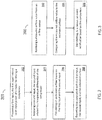
- Block 202 provides receiving a first input, the first input related to an input power of a motor for driving a compressor.
- a motor controller (not shown), such as a CMSC (common motor starter controller) provides a signal to control the input power to a motor coupled to a compressor.
- a general controller (or processor) can receive the input power supplied by the motor controller.
- Block 204 includes receiving a second input, the second input related to a temperature differential of the compressor.
- an inlet airflow temperature is measured by an inlet airflow temperature sensor located at an input to the compressor, and an outlet airflow temperature is measured by an outlet airflow temperature sensor located at an output of the compressor.
- the temperature differential represents the difference between the inlet airflow temperature and the outlet airflow temperature.
- the general controller can receive the second input which is the temperature differential.
- Block 206 provides calculating an estimated air flow based on the first input and the second input.
- an AHM air health management
- Block 208 provides exporting data associated with the first input, the second input, and the estimated airflow.
- the data received and calculated by the general controller can be stored in a memory and/or exported to a device.
- the device can be a display, computer device, or external memory or device.
- Block 302 provides receiving a measured airflow value from an airflow sensor.
- the airflow sensor can be any type of airflow sensor such as a Venturi flowmeter.
- a general controller or processor receives the measured airflow value from a sensor mounted to an aircraft.
- Block 304 includes comparing the measured airflow value to the estimated airflow.
- Block 306 further provides transmitting, to a device, an event notification based on the comparison.
- the event notification is an indication of a malfunctioning airflow sensor performing the measurement.
- an error margin of +/- 15% is used for determining a malfunctioning airflow sensor when comparing the measured airflow with the estimated airflow. If an error results outside of the error margin an event notification is transmitted to a device.
- data corresponding to the first input, second input, estimated airflow, and measured airflow for a configurable time period is stored and/or exported to an internal or external device. In an embodiment, this data can be provided to flight crews in real-time or provided at configured intervals. In one embodiment, the data can be downloaded and post-processed. In another embodiment, the data may be collected and processed for a configurable time period.
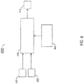
- the general controller 406 is configured to receive and process a plurality of data and is further configured to transmit the received input data and processed data.
- Airflow temperature sensors 402 of a compressor provide airflow temperature information to the general controller 406 that determines a temperature differential of the compressor using the inlet and outlet airflow temperatures from the temperature sensors 402.
- the motor controller 404 transmits the power value supplied to the motors used to drive the associated compressors.
- the general controller 406 is further configured to implement the AHM calculation provided above using the received input from temperature sensors 402 and the motor controller 404 to estimate an airflow pressure.
- the general controller 406 is capable of comparing the measured airflow pressure to the estimated airflow pressure and can further transmit the received inputs and processed data to an external/internal device 410 for storage or further processing.
- Collecting cruise data which requires in-flight testing, can allow for reliable temperature and pressure readings.
- the compressor will reach a study temperature and the pressure of the air at a cruising altitude will likely be more constant.
- the AHV are likely to be closed where modulating heat valves can substantially affect the temperature readings provided by the sensors.
- the AHVs When the AHVs are open, airflow external to the aircraft is allowed to enter the system and enter the compressor introducing variations due to fluctuations in the ambient airflow temperature. Therefore, the highest cruising altitudes will increase the probability of the AHVs being closed to provide reliable readings.
- the estimation comprises compensating the first and second input according to a modulation of an AHV, where the AHV provides at least a portion of the flow from a region proximate a first compressor outlet to a region proximate a first compressor inlet.
- a benefit realized by the disclosure provides for a reduction in CAC surges by responding to properly functioning flow sensors leading to efficient operation of the system.
- a technique for identifying defective flow sensors requiring maintenance is provided.
Landscapes
- Physics & Mathematics (AREA)
- Engineering & Computer Science (AREA)
- General Physics & Mathematics (AREA)
- Fluid Mechanics (AREA)
- Evolutionary Computation (AREA)
- Artificial Intelligence (AREA)
- Mathematical Physics (AREA)
- Automation & Control Theory (AREA)
- Aviation & Aerospace Engineering (AREA)
- Control Of Positive-Displacement Pumps (AREA)
- Control Of Positive-Displacement Air Blowers (AREA)
- Health & Medical Sciences (AREA)
- General Health & Medical Sciences (AREA)
- Pulmonology (AREA)
Abstract
Description
- The present disclosure relates to testing sensor equipment, and more particularly a prognostic for flow sensor BIT for motor driven compressor.
- Environmental control systems (ECS) are utilized on various types of aircraft for several purposes, such as air supply systems and/or cabin condition systems for the aircraft. For example, components of the ECS may be utilized to remove heat from various aircraft lubrication and electrical systems and/or used to condition aircraft cabin air. The cabin air conditioner includes one or more cabin air compressors (CACs), which compress air entering the system from an outside source or from a ram air system. The compressed air is delivered to an air cycle system and/or a vapor cycle system to bring it to a desired temperature then delivered to the aircraft cabin. After passing through the cabin, the air is typically exhausted to the outside. The CACs may be driven, for example, by air-cooled electric motors.
- Pneumatic air conditioning kit (PACK) flow sensors are required to be accurate to +/- 6% where failure modes occurring in the sensing hardware can generate unreliable readings. Errors associated with sensor readings can lead to uncertainty of operating points and can further lead to instability of a system. Malfunctioning flow sensors can cause undesirable surges effecting the operation of a compressor, where the surges cause a disruption of the airflow to the compressor. The motors driving these compressors respond to flow sensor readings. High flow sensor readings will cause the motor to throttle back while low flow sensor readings will cause the motor to consume more power while generating excessive airflow. These oscillations lead to inefficiencies in the power used to drive the compressors and further leads to unpredictable airflow from the system.
- PACK flow sensors may be equipped with BIT (built-in tests) for determining the operability of the flow sensor, however BIT are unable to detect various failures modes such as those failures that generate high flow readings which can induce a CAC surge. Another technique for detecting malfunctioning flow sensors requires using a redundant flow sensor configuration to determine a sensor drift between sensors. However, the redundant configuration increases the cost of operation and maintenance and further increases the processing and complexity of the system
- According to one embodiment, a computer-implemented method for a prognostic for flow sensor BIT for a motor driven compressor is provided. The method includes receiving a first input, the first input related to an input power of a motor for driving a compressor, and receiving a second input, the second input related to a temperature differential of the compressor. The method also includes calculating an estimated airflow based on the first input and the second input, and exporting data associated with the first input, the second input, and the estimated airflow.
- According to another embodiment, a system for performing a prognostic for a flow sensor BIT for a motor driven compressor is provided. The system includes a flow sensor and a compressor driven by a motor. The system is configured to receive a first input from a motor controller providing a signal to the motor and receive a second input from a temperature sensor equipment, the second input related to a temperature differential of the compressor. The system is also configured to calculate an estimated airflow based on the first input and the second input, and export data associated with the first input, the second input, and the estimated airflow.
- The subject matter, which is regarded as the present disclosure, is particularly pointed out and distinctly claimed in the claims at the conclusion of the specification. The foregoing and other features, and advantages of the present disclosure are apparent from the following detailed description taken in conjunction with the accompanying drawings in which:
-
FIG. 1 is a schematic illustration of a parallel compressor system in accordance with a flow sensor BIT for a motor driven compressor; -
FIG. 2 is a flow diagram illustrating a method of operating a flow sensor BIT for a motor driven compressor according to an embodiment; -
FIG. 3 is a flow diagram illustrating a method of operating a flow sensor BIT for a motor driven compressor according to another embodiment; and -
FIG. 4 is a schematic illustration of a system of operating a flow sensor BIT for a motor driven compressor according to an embodiment. - Referring to
FIG. 1 , an environmental control system (ECS) is schematically illustrated and referred to bynumeral 100. The ECS 100 is configured to condition air for various environments, such as an aircraft cabin. It is envisioned, however, that the ECS 100 may be used to condition numerous other environments and is not limited to use in the aircraft context. - The illustrated ECS 100 incudes a plurality of cabin air compressors (CACs). In the illustrated embodiment, theses CACs are shown as a
first compressor 12 and asecond compressor 14 and are operating in parallel. Amain inlet airflow 16 is supplied via a source, such as an external source or provided internally by a ram air system, for example. Themain inlet airflow 16 is diverted into two paths, resulting in afirst flow 18 and asecond flow 20 toward thefirst compressor 12 and thesecond compressor 14, respectively. - The
first flow 18 enters thefirst compressor 12 via afirst compressor inlet 22 at a first inlet temperature and exits thefirst compressor 12 via afirst compressor outlet 26 at a first outlet temperature, traveling through thefirst compressor 12 at a first flow rate (i.e.,compressor 12 fluidly directs thefirst flow 18 from theinput 22 to the output 26). Similarly, thesecond flow 20 enters thesecond compressor 14 via asecond compressor inlet 30 at a second inlet temperature and exits thesecond compressor 14 via asecond compressor outlet 34 at a second outlet temperature, traveling through thesecond compressor 14 at a second flow rate (i.e.,compressor 14 fluidly directs thesecond flow 20 from theinput 30 to the output 34). - The
first compressor 12 and thesecond compressor 14 are driven by afirst motor 38 at a first input power and asecond motor 42 at a second input power, respectively. The ECS 100 also includes at least one add heat valve (AHV), such as afirst AHV 46 and asecond AHV 48. The first AHV 46 is configured to recirculate air from a region proximate thefirst compressor outlet 26 to a region proximate thefirst compressor inlet 22, based on operational needs. Similarly, thesecond AHV 48 is configured to recirculate air from a region proximate thesecond compressor outlet 34 to a region proximate thesecond compressor inlet 30. Subsequent to passing through thefirst compressor 12 and thesecond compressor 14, thefirst flow 18 and thesecond flow 20 are directed to an air distribution system (not illustrated) either independently, or in combination, such as in amain outlet airflow 50, which is directed downstream to an air cycle system and/or a vapor cycle system, for example. - An inlet
airflow temperature sensor 62 is coupled tofirst flow 18 to measure the airflow temperature entering thefirst compressor 12. An outletairflow temperature sensor 64 is coupled to thefirst compressor outlet 26 to measure the airflow temperature as it leaves thefirst compressor 12. Also coupled to thefirst compressor outlet 26 is anoutput pressure sensor 68 for measuring the airflow pressure leaving thefirst compressor outlet 26. Asecond pressure sensor 66 is coupled to the path after theAHV 46 to measure the airflow pressure. Additionally, an inletairflow temperature sensor 72 is coupled tosecond flow 20 to measure the airflow temperature entering thesecond compressor 14. An outletairflow temperature sensor 74 is coupled to thesecond compressor outlet 34 to measure the airflow temperature as it leaves thesecond compressor 14. Also coupled to thesecond compressor outlet 34 is anoutput pressure sensor 78 for measuring the airflow pressure leaving thesecond compressor outlet 34. Asecond pressure sensor 76 is coupled to the path after theAHV 48 to measure the airflow pressure. - Referring now to
FIG. 2 , amethod 200 for performing a diagnostic for a flow sensor BIT (built-in test) for a motor driven compressor is shown.Block 202 provides receiving a first input, the first input related to an input power of a motor for driving a compressor. In an embodiment, a motor controller (not shown), such as a CMSC (common motor starter controller) provides a signal to control the input power to a motor coupled to a compressor. A general controller (or processor) can receive the input power supplied by the motor controller.Block 204 includes receiving a second input, the second input related to a temperature differential of the compressor. In an embodiment, an inlet airflow temperature is measured by an inlet airflow temperature sensor located at an input to the compressor, and an outlet airflow temperature is measured by an outlet airflow temperature sensor located at an output of the compressor. The temperature differential represents the difference between the inlet airflow temperature and the outlet airflow temperature. The general controller can receive the second input which is the temperature differential. - Block 206 provides calculating an estimated air flow based on the first input and the second input. In an embodiment, an AHM (air health management) calculation is performed by a general controller to estimate airflow. The calculation is provided as follows.


-
Block 208 provides exporting data associated with the first input, the second input, and the estimated airflow. In an embodiment, the data received and calculated by the general controller can be stored in a memory and/or exported to a device. As a non-limiting example, the device can be a display, computer device, or external memory or device. - Now referring to
FIG. 3 , amethod 300 in accordance with a further embodiment is shown.Block 302 provides receiving a measured airflow value from an airflow sensor. It is known to one of ordinary skill in the art the airflow sensor can be any type of airflow sensor such as a Venturi flowmeter. In an embodiment, a general controller (or processor) receives the measured airflow value from a sensor mounted to an aircraft.Block 304 includes comparing the measured airflow value to the estimated airflow. -
Block 306 further provides transmitting, to a device, an event notification based on the comparison. In an embodiment, the event notification is an indication of a malfunctioning airflow sensor performing the measurement. In one embodiment, an error margin of +/- 15% is used for determining a malfunctioning airflow sensor when comparing the measured airflow with the estimated airflow. If an error results outside of the error margin an event notification is transmitted to a device. In a different embodiment, data corresponding to the first input, second input, estimated airflow, and measured airflow for a configurable time period is stored and/or exported to an internal or external device. In an embodiment, this data can be provided to flight crews in real-time or provided at configured intervals. In one embodiment, the data can be downloaded and post-processed. In another embodiment, the data may be collected and processed for a configurable time period. - Now referring to
FIG. 4 , an embodiment of asystem 400 of operating a flow sensor BIT for a motor driven compressor is provided. Thegeneral controller 406 is configured to receive and process a plurality of data and is further configured to transmit the received input data and processed data.Airflow temperature sensors 402 of a compressor provide airflow temperature information to thegeneral controller 406 that determines a temperature differential of the compressor using the inlet and outlet airflow temperatures from thetemperature sensors 402. Themotor controller 404 transmits the power value supplied to the motors used to drive the associated compressors. Thegeneral controller 406 is further configured to implement the AHM calculation provided above using the received input fromtemperature sensors 402 and themotor controller 404 to estimate an airflow pressure. Thegeneral controller 406 is capable of comparing the measured airflow pressure to the estimated airflow pressure and can further transmit the received inputs and processed data to an external/internal device 410 for storage or further processing. - Collecting cruise data, which requires in-flight testing, can allow for reliable temperature and pressure readings. The compressor will reach a study temperature and the pressure of the air at a cruising altitude will likely be more constant. In addition, the AHV are likely to be closed where modulating heat valves can substantially affect the temperature readings provided by the sensors. When the AHVs are open, airflow external to the aircraft is allowed to enter the system and enter the compressor introducing variations due to fluctuations in the ambient airflow temperature. Therefore, the highest cruising altitudes will increase the probability of the AHVs being closed to provide reliable readings. Ground taxi data, data collected as the aircraft is taxiing on the runway, can suffer as the AHVs are likely to be open due to the cooler ambient temperatures causing a variation in airflow temperature readings. In a different embodiment, the estimation comprises compensating the first and second input according to a modulation of an AHV, where the AHV provides at least a portion of the flow from a region proximate a first compressor outlet to a region proximate a first compressor inlet.
- A benefit realized by the disclosure provides for a reduction in CAC surges by responding to properly functioning flow sensors leading to efficient operation of the system. In addition, a technique for identifying defective flow sensors requiring maintenance is provided. While the present disclosure has been described in detail in connection with only a limited number of embodiments, it should be readily understood that the present disclosure is not limited to such disclosed embodiments. Rather, the present disclosure can be modified to incorporate any number of variations, alterations, substitutions or equivalent arrangements not heretofore described, but which are commensurate with the scope of the present invention as defined by the claims. Additionally, while various embodiments of the present disclosure have been described, it is to be understood that aspects of the present disclosure may include only some of the described embodiments. Accordingly, the present disclosure is not to be seen as limited by the foregoing description, but is only limited by the scope of the appended claims.
Claims (15)
- A computer-implemented method for prognostic for flow sensor, the method comprising:receiving a first input, the first input related to an input power of a motor for driving a compressor;receiving a second input, the second input related to a temperature differential of the compressor;calculating an estimated air flow based on the first input and the second input; andexporting data associated with the first input, the second input, and the estimated airflow.
- The method of claim 1, wherein the first input is a power supplied to the motor driving a compressor.
- The method of claim 1 or 2, wherein the second input is a temperature differential of an inlet airflow temperature of the compressor and an outlet airflow temperature of the compressor.
- The method of any preceding claim, further comprising receiving a measured airflow value from an flow sensor; and
comparing the measured airflow value to the estimated airflow. - The method of claim 4, further comprising transmitting to a device (410), an event notification based the comparison.
- The method of claim 5, wherein the event notification indicates an error, and wherein the transmitting the event notification is responsive to exceeding an error margin.
- The method of claim 4, further comprising exporting data corresponding to the first input, the second input, the estimated airflow, and the measured airflow over a specified time period.
- A system for performing a prognostic for a flow sensor, the system comprising:a flow sensor;a compressor (12) driven by a motor (38);the system configured to:receive a first input from a motor controller (404) providing a signal to the motor;receive a second input from a temperature sensor equipment (402), the second input related to a temperature differential of the compressor;calculate an estimated airflow based on the first input and the second input; andexport data associated with the first input, the second input, and the estimated airflow.
- The system of claim 8, wherein the first input is a power supplied to the motor driving a compressor.
- The system of claim 8 or 9, wherein the second input is a temperature differential of an inlet airflow temperature of the compressor and an outlet airflow temperature of the compressor, where the inlet airflow temperature is measured by an inlet airflow temperature sensor and the outlet airflow temperature is measured by an outlet airflow temperature sensor.
- The system of claim 8, 9 or 10, further comprising receiving a measured airflow value from an flow sensor; and
comparing the measured airflow value to the estimated airflow. - The system of claim 11, further comprising transmitting to a device (410), an event notification based the comparison.
- The system of claim 12, wherein the event notification indicates an error, and wherein the transmitting the event notification is responsive to the comparison exceeding an error margin.
- The system of claim 11, further comprising exporting data corresponding to the first input, the second input, the estimated airflow, and the measured airflow over a specified time period.
- The system of any of claims 8 to 14, wherein the flow sensor is a Venturi flow meter.
Applications Claiming Priority (1)
| Application Number | Priority Date | Filing Date | Title |
|---|---|---|---|
| US15/096,861 US10161783B2 (en) | 2016-04-12 | 2016-04-12 | Flow sensor bit for motor driven compressor |
Publications (2)
| Publication Number | Publication Date |
|---|---|
| EP3232283A1 true EP3232283A1 (en) | 2017-10-18 |
| EP3232283B1 EP3232283B1 (en) | 2019-10-23 |
Family
ID=58547353
Family Applications (1)
| Application Number | Title | Priority Date | Filing Date |
|---|---|---|---|
| EP17166209.1A Active EP3232283B1 (en) | 2016-04-12 | 2017-04-12 | Flow sensor bit for motor driven compressor |
Country Status (2)
| Country | Link |
|---|---|
| US (1) | US10161783B2 (en) |
| EP (1) | EP3232283B1 (en) |
Cited By (1)
| Publication number | Priority date | Publication date | Assignee | Title |
|---|---|---|---|---|
| US12241473B2 (en) | 2023-08-03 | 2025-03-04 | Garrett Transportation I Inc. | Methods and systems of compressor control with surge avoidance and response |
Families Citing this family (4)
| Publication number | Priority date | Publication date | Assignee | Title |
|---|---|---|---|---|
| US20180162537A1 (en) * | 2016-12-09 | 2018-06-14 | United Technologies Corporation | Environmental control system air circuit |
| US10934979B2 (en) * | 2017-05-30 | 2021-03-02 | Ford Global Technologies, Llc | Methods and system diagnosing a variable geometry compressor for an internal combustion engine |
| US12535075B2 (en) | 2023-10-27 | 2026-01-27 | Garrett Transportation I Inc. | Multi-stage electric compressor energy consumption optimization |
| US12546522B2 (en) | 2023-12-20 | 2026-02-10 | Garrett Transportation I Inc. | Compressor control in a vapor compression cooling cycle |
Citations (1)
| Publication number | Priority date | Publication date | Assignee | Title |
|---|---|---|---|---|
| US20150197339A1 (en) * | 2012-01-04 | 2015-07-16 | The Boeing Company | Aircraft Environmental Control System and Method |
Family Cites Families (9)
| Publication number | Priority date | Publication date | Assignee | Title |
|---|---|---|---|---|
| US6427471B1 (en) | 2000-02-29 | 2002-08-06 | Shimadzu Corporation | Air cycle machine and air conditioning system using the same |
| US7240567B2 (en) * | 2003-10-30 | 2007-07-10 | Invensys Systems, Inc. | Dynamic response characteristics of flow meters |
| US7055366B2 (en) * | 2004-05-21 | 2006-06-06 | Upchurch Scientific, Inc. | Flow sensor calibration methods and apparatus |
| JP5812653B2 (en) * | 2011-03-31 | 2015-11-17 | 三菱重工業株式会社 | Heat medium flow rate estimation device, heat source machine, and heat medium flow rate estimation method |
| US20130060492A1 (en) * | 2011-09-06 | 2013-03-07 | Techox Industries Ind. | Method of deducing time based metrics using flow rate |
| US9126687B2 (en) | 2012-03-05 | 2015-09-08 | Hamilton Sundstrand Corporation | Environmental control system having parallel compressors and method of controllably operating |
| JP5906388B2 (en) * | 2012-05-17 | 2016-04-20 | パナソニックIpマネジメント株式会社 | Flow measuring device |
| US10753361B2 (en) * | 2014-04-25 | 2020-08-25 | Sensia Llc | ESP pump flow rate estimation and control |
| GB2543048B (en) * | 2015-10-05 | 2022-06-08 | Equinor Energy As | Estimating flow rate at a pump |
-
2016
- 2016-04-12 US US15/096,861 patent/US10161783B2/en active Active
-
2017
- 2017-04-12 EP EP17166209.1A patent/EP3232283B1/en active Active
Patent Citations (1)
| Publication number | Priority date | Publication date | Assignee | Title |
|---|---|---|---|---|
| US20150197339A1 (en) * | 2012-01-04 | 2015-07-16 | The Boeing Company | Aircraft Environmental Control System and Method |
Non-Patent Citations (1)
| Title |
|---|
| ESBER ANDIROGLU: "DEVELOPMENT OF VIRTUAL AIR / WATER FLOW METERS USINGFAN / PUMP HEAD AND MOTOR POWER", August 2015 (2015-08-01), XP002773194, Retrieved from the Internet <URL:https://search.proquest.com/docview/1718418473/3C7A1821BFA544F8PQ/1?accountid=29404> [retrieved on 20170825] * |
Cited By (1)
| Publication number | Priority date | Publication date | Assignee | Title |
|---|---|---|---|---|
| US12241473B2 (en) | 2023-08-03 | 2025-03-04 | Garrett Transportation I Inc. | Methods and systems of compressor control with surge avoidance and response |
Also Published As
| Publication number | Publication date |
|---|---|
| EP3232283B1 (en) | 2019-10-23 |
| US20170292872A1 (en) | 2017-10-12 |
| US10161783B2 (en) | 2018-12-25 |
Similar Documents
| Publication | Publication Date | Title |
|---|---|---|
| EP3232283B1 (en) | Flow sensor bit for motor driven compressor | |
| CN107168205B (en) | A kind of online health monitoring data collection and analysis method of civil aircraft air-conditioning system | |
| US9317249B2 (en) | Operations support systems and methods for calculating and evaluating turbine temperatures and health | |
| US8321118B2 (en) | Operations support systems and methods with power assurance | |
| CN104149988B (en) | The method for diagnosing bleed air system failure | |
| US9366192B2 (en) | Hazardous gas detection system for a gas turbine enclosure | |
| CN105593118B (en) | Method for diagnosing faults in auxiliary power units | |
| US12264990B2 (en) | Method and a system for monitoring the state of an exchanger in an air circuit of an aircraft | |
| EP2207072A2 (en) | Operations support systems and methods with engine diagnostics | |
| US10571316B2 (en) | Method and system for determining the flow rate of air collected from an aircraft engine | |
| EP2202147A1 (en) | Operations support systems and methods for power management | |
| US9862495B2 (en) | Aircraft air-conditioning heat exchanger contamination detection | |
| US9310276B2 (en) | Method and device for determining the air bleed on an aircraft turbojet engine | |
| US10451491B2 (en) | System and method to determine total air temperature from turbofan bypass flow temperature | |
| US7801695B2 (en) | Operations support systems and methods with model-based torque estimates | |
| US10900880B2 (en) | Cabin air control system for an aircraft | |
| WO2013127994A2 (en) | Method and system for real time dry low nitrogen oxide (dln) and diffusion combustion monitoring | |
| EP3839684A1 (en) | Method and system for diagnosing an engine or an aircraft | |
| US20220161931A1 (en) | Environmental control system performance monitoring | |
| US9021877B2 (en) | Method and device for determining an air mass flow flowing through a ram air channel | |
| EP3543135A1 (en) | Heat exchanger blockage detection | |
| EP4502388A2 (en) | Cabin air compressor failure alert system | |
| HK40119688A (en) | Cabin air compressor failure alert system | |
| HK40079879B (en) | Method and computer program product for monitoring an aircraft bleed air system |
Legal Events
| Date | Code | Title | Description |
|---|---|---|---|
| PUAI | Public reference made under article 153(3) epc to a published international application that has entered the european phase |
Free format text: ORIGINAL CODE: 0009012 |
|
| STAA | Information on the status of an ep patent application or granted ep patent |
Free format text: STATUS: THE APPLICATION HAS BEEN PUBLISHED |
|
| AK | Designated contracting states |
Kind code of ref document: A1 Designated state(s): AL AT BE BG CH CY CZ DE DK EE ES FI FR GB GR HR HU IE IS IT LI LT LU LV MC MK MT NL NO PL PT RO RS SE SI SK SM TR |
|
| AX | Request for extension of the european patent |
Extension state: BA ME |
|
| STAA | Information on the status of an ep patent application or granted ep patent |
Free format text: STATUS: REQUEST FOR EXAMINATION WAS MADE |
|
| 17P | Request for examination filed |
Effective date: 20180418 |
|
| RBV | Designated contracting states (corrected) |
Designated state(s): AL AT BE BG CH CY CZ DE DK EE ES FI FR GB GR HR HU IE IS IT LI LT LU LV MC MK MT NL NO PL PT RO RS SE SI SK SM TR |
|
| STAA | Information on the status of an ep patent application or granted ep patent |
Free format text: STATUS: EXAMINATION IS IN PROGRESS |
|
| 17Q | First examination report despatched |
Effective date: 20180817 |
|
| REG | Reference to a national code |
Ref country code: DE Ref legal event code: R079 Ref document number: 602017007964 Country of ref document: DE Free format text: PREVIOUS MAIN CLASS: G05B0023020000 Ipc: G01F0025000000 |
|
| GRAP | Despatch of communication of intention to grant a patent |
Free format text: ORIGINAL CODE: EPIDOSNIGR1 |
|
| STAA | Information on the status of an ep patent application or granted ep patent |
Free format text: STATUS: GRANT OF PATENT IS INTENDED |
|
| RIC1 | Information provided on ipc code assigned before grant |
Ipc: G05B 23/02 20060101ALI20190418BHEP Ipc: G01F 25/00 20060101AFI20190418BHEP Ipc: B64D 45/00 20060101ALI20190418BHEP Ipc: G01F 1/44 20060101ALI20190418BHEP Ipc: B64D 1/00 20060101ALI20190418BHEP |
|
| INTG | Intention to grant announced |
Effective date: 20190514 |
|
| RIN1 | Information on inventor provided before grant (corrected) |
Inventor name: ZYWIAK, THOMAS M. |
|
| RAP1 | Party data changed (applicant data changed or rights of an application transferred) |
Owner name: HAMILTON SUNDSTRAND CORPORATION |
|
| GRAS | Grant fee paid |
Free format text: ORIGINAL CODE: EPIDOSNIGR3 |
|
| GRAA | (expected) grant |
Free format text: ORIGINAL CODE: 0009210 |
|
| STAA | Information on the status of an ep patent application or granted ep patent |
Free format text: STATUS: THE PATENT HAS BEEN GRANTED |
|
| AK | Designated contracting states |
Kind code of ref document: B1 Designated state(s): AL AT BE BG CH CY CZ DE DK EE ES FI FR GB GR HR HU IE IS IT LI LT LU LV MC MK MT NL NO PL PT RO RS SE SI SK SM TR |
|
| REG | Reference to a national code |
Ref country code: GB Ref legal event code: FG4D |
|
| REG | Reference to a national code |
Ref country code: CH Ref legal event code: EP |
|
| REG | Reference to a national code |
Ref country code: IE Ref legal event code: FG4D |
|
| REG | Reference to a national code |
Ref country code: DE Ref legal event code: R096 Ref document number: 602017007964 Country of ref document: DE |
|
| REG | Reference to a national code |
Ref country code: AT Ref legal event code: REF Ref document number: 1194170 Country of ref document: AT Kind code of ref document: T Effective date: 20191115 |
|
| REG | Reference to a national code |
Ref country code: NL Ref legal event code: MP Effective date: 20191023 |
|
| REG | Reference to a national code |
Ref country code: LT Ref legal event code: MG4D |
|
| PG25 | Lapsed in a contracting state [announced via postgrant information from national office to epo] |
Ref country code: SE Free format text: LAPSE BECAUSE OF FAILURE TO SUBMIT A TRANSLATION OF THE DESCRIPTION OR TO PAY THE FEE WITHIN THE PRESCRIBED TIME-LIMIT Effective date: 20191023 Ref country code: LV Free format text: LAPSE BECAUSE OF FAILURE TO SUBMIT A TRANSLATION OF THE DESCRIPTION OR TO PAY THE FEE WITHIN THE PRESCRIBED TIME-LIMIT Effective date: 20191023 Ref country code: LT Free format text: LAPSE BECAUSE OF FAILURE TO SUBMIT A TRANSLATION OF THE DESCRIPTION OR TO PAY THE FEE WITHIN THE PRESCRIBED TIME-LIMIT Effective date: 20191023 Ref country code: NL Free format text: LAPSE BECAUSE OF FAILURE TO SUBMIT A TRANSLATION OF THE DESCRIPTION OR TO PAY THE FEE WITHIN THE PRESCRIBED TIME-LIMIT Effective date: 20191023 Ref country code: BG Free format text: LAPSE BECAUSE OF FAILURE TO SUBMIT A TRANSLATION OF THE DESCRIPTION OR TO PAY THE FEE WITHIN THE PRESCRIBED TIME-LIMIT Effective date: 20200123 Ref country code: PT Free format text: LAPSE BECAUSE OF FAILURE TO SUBMIT A TRANSLATION OF THE DESCRIPTION OR TO PAY THE FEE WITHIN THE PRESCRIBED TIME-LIMIT Effective date: 20200224 Ref country code: FI Free format text: LAPSE BECAUSE OF FAILURE TO SUBMIT A TRANSLATION OF THE DESCRIPTION OR TO PAY THE FEE WITHIN THE PRESCRIBED TIME-LIMIT Effective date: 20191023 Ref country code: NO Free format text: LAPSE BECAUSE OF FAILURE TO SUBMIT A TRANSLATION OF THE DESCRIPTION OR TO PAY THE FEE WITHIN THE PRESCRIBED TIME-LIMIT Effective date: 20200123 Ref country code: PL Free format text: LAPSE BECAUSE OF FAILURE TO SUBMIT A TRANSLATION OF THE DESCRIPTION OR TO PAY THE FEE WITHIN THE PRESCRIBED TIME-LIMIT Effective date: 20191023 Ref country code: GR Free format text: LAPSE BECAUSE OF FAILURE TO SUBMIT A TRANSLATION OF THE DESCRIPTION OR TO PAY THE FEE WITHIN THE PRESCRIBED TIME-LIMIT Effective date: 20200124 |
|
| PG25 | Lapsed in a contracting state [announced via postgrant information from national office to epo] |
Ref country code: HR Free format text: LAPSE BECAUSE OF FAILURE TO SUBMIT A TRANSLATION OF THE DESCRIPTION OR TO PAY THE FEE WITHIN THE PRESCRIBED TIME-LIMIT Effective date: 20191023 Ref country code: IS Free format text: LAPSE BECAUSE OF FAILURE TO SUBMIT A TRANSLATION OF THE DESCRIPTION OR TO PAY THE FEE WITHIN THE PRESCRIBED TIME-LIMIT Effective date: 20200224 Ref country code: RS Free format text: LAPSE BECAUSE OF FAILURE TO SUBMIT A TRANSLATION OF THE DESCRIPTION OR TO PAY THE FEE WITHIN THE PRESCRIBED TIME-LIMIT Effective date: 20191023 |
|
| PG25 | Lapsed in a contracting state [announced via postgrant information from national office to epo] |
Ref country code: AL Free format text: LAPSE BECAUSE OF FAILURE TO SUBMIT A TRANSLATION OF THE DESCRIPTION OR TO PAY THE FEE WITHIN THE PRESCRIBED TIME-LIMIT Effective date: 20191023 |
|
| REG | Reference to a national code |
Ref country code: DE Ref legal event code: R097 Ref document number: 602017007964 Country of ref document: DE |
|
| PG2D | Information on lapse in contracting state deleted |
Ref country code: IS |
|
| PG25 | Lapsed in a contracting state [announced via postgrant information from national office to epo] |
Ref country code: CZ Free format text: LAPSE BECAUSE OF FAILURE TO SUBMIT A TRANSLATION OF THE DESCRIPTION OR TO PAY THE FEE WITHIN THE PRESCRIBED TIME-LIMIT Effective date: 20191023 Ref country code: RO Free format text: LAPSE BECAUSE OF FAILURE TO SUBMIT A TRANSLATION OF THE DESCRIPTION OR TO PAY THE FEE WITHIN THE PRESCRIBED TIME-LIMIT Effective date: 20191023 Ref country code: ES Free format text: LAPSE BECAUSE OF FAILURE TO SUBMIT A TRANSLATION OF THE DESCRIPTION OR TO PAY THE FEE WITHIN THE PRESCRIBED TIME-LIMIT Effective date: 20191023 Ref country code: EE Free format text: LAPSE BECAUSE OF FAILURE TO SUBMIT A TRANSLATION OF THE DESCRIPTION OR TO PAY THE FEE WITHIN THE PRESCRIBED TIME-LIMIT Effective date: 20191023 Ref country code: DK Free format text: LAPSE BECAUSE OF FAILURE TO SUBMIT A TRANSLATION OF THE DESCRIPTION OR TO PAY THE FEE WITHIN THE PRESCRIBED TIME-LIMIT Effective date: 20191023 Ref country code: IS Free format text: LAPSE BECAUSE OF FAILURE TO SUBMIT A TRANSLATION OF THE DESCRIPTION OR TO PAY THE FEE WITHIN THE PRESCRIBED TIME-LIMIT Effective date: 20200223 |
|
| REG | Reference to a national code |
Ref country code: AT Ref legal event code: MK05 Ref document number: 1194170 Country of ref document: AT Kind code of ref document: T Effective date: 20191023 |
|
| PLBE | No opposition filed within time limit |
Free format text: ORIGINAL CODE: 0009261 |
|
| STAA | Information on the status of an ep patent application or granted ep patent |
Free format text: STATUS: NO OPPOSITION FILED WITHIN TIME LIMIT |
|
| PG25 | Lapsed in a contracting state [announced via postgrant information from national office to epo] |
Ref country code: IT Free format text: LAPSE BECAUSE OF FAILURE TO SUBMIT A TRANSLATION OF THE DESCRIPTION OR TO PAY THE FEE WITHIN THE PRESCRIBED TIME-LIMIT Effective date: 20191023 Ref country code: SK Free format text: LAPSE BECAUSE OF FAILURE TO SUBMIT A TRANSLATION OF THE DESCRIPTION OR TO PAY THE FEE WITHIN THE PRESCRIBED TIME-LIMIT Effective date: 20191023 Ref country code: SM Free format text: LAPSE BECAUSE OF FAILURE TO SUBMIT A TRANSLATION OF THE DESCRIPTION OR TO PAY THE FEE WITHIN THE PRESCRIBED TIME-LIMIT Effective date: 20191023 |
|
| 26N | No opposition filed |
Effective date: 20200724 |
|
| REG | Reference to a national code |
Ref country code: DE Ref legal event code: R119 Ref document number: 602017007964 Country of ref document: DE |
|
| PG25 | Lapsed in a contracting state [announced via postgrant information from national office to epo] |
Ref country code: MC Free format text: LAPSE BECAUSE OF FAILURE TO SUBMIT A TRANSLATION OF THE DESCRIPTION OR TO PAY THE FEE WITHIN THE PRESCRIBED TIME-LIMIT Effective date: 20191023 Ref country code: SI Free format text: LAPSE BECAUSE OF FAILURE TO SUBMIT A TRANSLATION OF THE DESCRIPTION OR TO PAY THE FEE WITHIN THE PRESCRIBED TIME-LIMIT Effective date: 20191023 Ref country code: AT Free format text: LAPSE BECAUSE OF FAILURE TO SUBMIT A TRANSLATION OF THE DESCRIPTION OR TO PAY THE FEE WITHIN THE PRESCRIBED TIME-LIMIT Effective date: 20191023 |
|
| REG | Reference to a national code |
Ref country code: CH Ref legal event code: PL |
|
| PG25 | Lapsed in a contracting state [announced via postgrant information from national office to epo] |
Ref country code: CH Free format text: LAPSE BECAUSE OF NON-PAYMENT OF DUE FEES Effective date: 20200430 Ref country code: LI Free format text: LAPSE BECAUSE OF NON-PAYMENT OF DUE FEES Effective date: 20200430 Ref country code: DE Free format text: LAPSE BECAUSE OF NON-PAYMENT OF DUE FEES Effective date: 20201103 Ref country code: LU Free format text: LAPSE BECAUSE OF NON-PAYMENT OF DUE FEES Effective date: 20200412 |
|
| REG | Reference to a national code |
Ref country code: BE Ref legal event code: MM Effective date: 20200430 |
|
| PG25 | Lapsed in a contracting state [announced via postgrant information from national office to epo] |
Ref country code: BE Free format text: LAPSE BECAUSE OF NON-PAYMENT OF DUE FEES Effective date: 20200430 |
|
| PG25 | Lapsed in a contracting state [announced via postgrant information from national office to epo] |
Ref country code: IE Free format text: LAPSE BECAUSE OF NON-PAYMENT OF DUE FEES Effective date: 20200412 |
|
| PG25 | Lapsed in a contracting state [announced via postgrant information from national office to epo] |
Ref country code: TR Free format text: LAPSE BECAUSE OF FAILURE TO SUBMIT A TRANSLATION OF THE DESCRIPTION OR TO PAY THE FEE WITHIN THE PRESCRIBED TIME-LIMIT Effective date: 20191023 Ref country code: MT Free format text: LAPSE BECAUSE OF FAILURE TO SUBMIT A TRANSLATION OF THE DESCRIPTION OR TO PAY THE FEE WITHIN THE PRESCRIBED TIME-LIMIT Effective date: 20191023 Ref country code: CY Free format text: LAPSE BECAUSE OF FAILURE TO SUBMIT A TRANSLATION OF THE DESCRIPTION OR TO PAY THE FEE WITHIN THE PRESCRIBED TIME-LIMIT Effective date: 20191023 |
|
| PG25 | Lapsed in a contracting state [announced via postgrant information from national office to epo] |
Ref country code: MK Free format text: LAPSE BECAUSE OF FAILURE TO SUBMIT A TRANSLATION OF THE DESCRIPTION OR TO PAY THE FEE WITHIN THE PRESCRIBED TIME-LIMIT Effective date: 20191023 |
|
| P01 | Opt-out of the competence of the unified patent court (upc) registered |
Effective date: 20230522 |
|
| PGFP | Annual fee paid to national office [announced via postgrant information from national office to epo] |
Ref country code: GB Payment date: 20260319 Year of fee payment: 10 |
|
| PGFP | Annual fee paid to national office [announced via postgrant information from national office to epo] |
Ref country code: FR Payment date: 20260319 Year of fee payment: 10 |