EP3232207A1 - Method and system for measuring imbalances in an electrical grid - Google Patents
Method and system for measuring imbalances in an electrical grid Download PDFInfo
- Publication number
- EP3232207A1 EP3232207A1 EP15867012.5A EP15867012A EP3232207A1 EP 3232207 A1 EP3232207 A1 EP 3232207A1 EP 15867012 A EP15867012 A EP 15867012A EP 3232207 A1 EP3232207 A1 EP 3232207A1
- Authority
- EP
- European Patent Office
- Prior art keywords
- cos
- sin
- voltage
- imbalance
- power vector
- Prior art date
- Legal status (The legal status is an assumption and is not a legal conclusion. Google has not performed a legal analysis and makes no representation as to the accuracy of the status listed.)
- Granted
Links
Images


Classifications
-
- G—PHYSICS
- G01—MEASURING; TESTING
- G01R—MEASURING ELECTRIC VARIABLES; MEASURING MAGNETIC VARIABLES
- G01R19/00—Arrangements for measuring currents or voltages or for indicating presence or sign thereof
- G01R19/25—Arrangements for measuring currents or voltages or for indicating presence or sign thereof using digital measurement techniques
- G01R19/2513—Arrangements for monitoring electric power systems, e.g. power lines or loads; Logging
-
- G—PHYSICS
- G01—MEASURING; TESTING
- G01R—MEASURING ELECTRIC VARIABLES; MEASURING MAGNETIC VARIABLES
- G01R21/00—Arrangements for measuring electric power or power factor
- G01R21/001—Measuring real or reactive component; Measuring apparent energy
- G01R21/003—Measuring reactive component
-
- G—PHYSICS
- G01—MEASURING; TESTING
- G01R—MEASURING ELECTRIC VARIABLES; MEASURING MAGNETIC VARIABLES
- G01R21/00—Arrangements for measuring electric power or power factor
- G01R21/06—Arrangements for measuring electric power or power factor by measuring current and voltage
Definitions
- the present invention generally relates to the field of the control and maintenance of electrical grids and systems, and more specifically to measuring the energetic effects of voltage imbalances on the operation of three- and four-wire three-phase electrical systems, with balanced and unbalanced receivers.
- Spanish patent ES 2 316 280 B1 discloses a method and system for measuring the so-called "imbalance power phasor" ( A u ), a term that was used for the first time in said patent.
- the modulus of the imbalance power phasor coincides with the value of S u when system voltages are balanced.
- the imbalance power phasor is useful for measuring the effects of load imbalances and prevents some of the problems with imbalance power S u .
- the imbalance power phasor presents certain advantages with respect to S u . However, it does not measure the effects caused by voltage imbalances; therefore, use thereof is limited to the analysis of imbalances produced by electrical loads when supply voltages are perfectly balanced or have very minor imbalances.
- the present invention discloses a method for measuring imbalances in an electrical grid comprising the steps of:
- the present invention also discloses a system for measuring imbalances in an electrical grid, comprising:
- the present invention provides a method and system for measuring imbalances in an electrical grid, based on the calculation of a new magnitude referred to as "imbalance power vector,” as will be defined herein below.
- the imbalance power vector provides information about imbalances produced in an electrical grid due to effects of both load and voltage imbalances that is more precise than what was made available up until now in the prior art.
- the method and system of the present invention will be very useful in a wide range of specific applications, such as for example measuring instruments, protection instruments, machine regulating equipment, active filters, electric machine maintenance, etc.
- the method and system for measuring disclosed in the present invention are based on the calculation of a magnitude herein referred to as "imbalance power vector" ( S u ). It is of a vector magnitude, i.e., it is defined in a three-dimensional space and has modulus, direction and sense. The modulus is always equal to the value of the imbalance power S u , in systems with both balanced voltages and unbalanced voltages.
- Figures 1 and 2 depict a graphic representation and block diagram representation, respectively, of the imbalance power vector and the relationships with its various components.
- the first component, S ui measures the exclusive effects of load imbalances S ⁇ ui b together with the effects originated thereon by voltage imbalances ( S uiv ); this component of the imbalance power vector is represented in the plane defined by coordinate axes p , q . Therefore, plane ( p , q ) constitutes the joint domain of load and voltage imbalances.
- the second component, S uv of the imbalance power vector determines the exclusive effect of voltage imbalances and is represented on axis z (domain of voltage imbalances), orthogonal to plane ( p , q ).
- vector S uvT the vector sum of S uiv and S uv , defines the total effect of voltage imbalances on the electrical grid being studied.
- the imbalance power vector and its components allow obtaining quality factors offering information about the effects of imbalances on electrical grids, assessing the exclusive load imbalance or the exclusive voltage imbalance with respect to the total imbalance of the system, as well as the relative importance of resistive and reactive load imbalances, among others.
- the total imbalance power in an electrical system or grid can be obtained as the modulus of the vector resulting from the vector sum of the imbalance power vectors of each of the integrating parts thereof.
- FIG. 3 a block diagram depicting a method according to the preferred embodiment of the present invention is shown, comprising the steps of:
- the electrical signals acquired by means of the physical system for measuring are the instantaneous values of voltage (v A , v B , v C ) and intensity (i A , i B , ic) of the phases (A, B, C) at the point of the electrical grid where the measurement is being taken.
- Digital processing in turn consists of separating their components at the fundamental frequency (v A1 , v B1 , v C1 ), (i A1 , i B1 , i C1 ).
- the method comprises, in addition to or instead of step (5) of displaying described above, a step of emitting an alarm when the calculated value of at least one of the imbalance power vector ( S u ), its component S ui and its component S uv exceeds a given threshold.
- the alarm can be of any suitable type in a specific application, for example a visual and/or acoustic alarm.
- the method thereby warns an operator that a voltage and/or load imbalance that may have serious effects on the electrical grid in question is taking place such that the operator can take the appropriate measures (for example cutting off the power supply to that part of the electrical grid) to protect the circuit and the apparatus connected thereto.
- the system comprises voltage and intensity measurement sensors (8) for measuring instantaneous values of voltage and intensity; a signal conditioner (9) for adapting the secondary current of each measurement sensor (8) to the voltage applicable to analog inputs of an acquisition card (10); said acquisition card (10) converting the analog voltage and intensity signals into a series of discrete samples used as input in an acquisition module (13); a processing system (11) with a motherboard in which the acquisition card (10) is placed so that the discrete samples of the voltage and intensity signals can be exchanged with the acquisition module (13); and a touch screen (12) acting as the display device, connected to a display module (18) for visually presenting at least one value calculated by the system for measuring: for example voltages, intensities, active and reactive powers, symmetrical components, imbalance power vector and its components, in modulus and argument form, in addition to the graphic representation thereof.
- system for measuring according to the preferred embodiment of the present invention also comprises the following modules:
- the system comprises, in addition to or instead of the display module (18), an alarm module configured for emitting an alarm when the calculated value of at least one of the imbalance power vector ( S u ), its component S ui and its component S uv exceeds a given threshold.
- an alarm module configured for emitting an alarm when the calculated value of at least one of the imbalance power vector ( S u ), its component S ui and its component S uv exceeds a given threshold.
- a system for measuring such as the one described herein above is practically useful in a range of specific applications, such as the following in a non-limiting manner, for example:
- the system disclosed herein allows accurately measuring energies corresponding to voltage imbalances separately from those caused by load imbalances, therefore providing the information required to act on the control circuit of the DFIG converter, thereby keeping the turbine running and minimizing energies caused by imbalances.
- the three output (secondary) voltages of the autotransformer were adjusted to 115.4 V and the active power (P), the reactive power (Q), the imbalance power phasor (A u ) and the imbalance power vector (S u ) were recorded in a measuring instrument (digital wattmeter). The results are shown in Table 1 below.
Landscapes
- Engineering & Computer Science (AREA)
- Power Engineering (AREA)
- Physics & Mathematics (AREA)
- General Physics & Mathematics (AREA)
- Supply And Distribution Of Alternating Current (AREA)
Abstract
Description
- The present invention generally relates to the field of the control and maintenance of electrical grids and systems, and more specifically to measuring the energetic effects of voltage imbalances on the operation of three- and four-wire three-phase electrical systems, with balanced and unbalanced receivers.
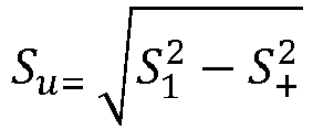
- Different formulations are known in the prior art for imbalance power, which is the magnitude in charge of measuring the effects of imbalances on electrical systems (see, for example, L.S. Czarnecki, "Power related phenomena in three-phase unbalanced systems", IEEE Trans on Power Delivery, vol. 10, no. 3, July 1995; A. E. Emanuel, "The Buchholz-Goodhue Apparent Power definition: The practical approach for non-sinusoidal and unbalanced systems", IEEE Trans on Power Delivery, vol. 13, no. 2, April 1998). A much-used expression of the imbalance power (Su) is the following, included in the draft for IEEE standard 1459-2010, of the Institute of Electrical and Electronic Engineers of the United States of America, depending on the apparent power at the fundamental frequency (S1) and the positive-sequence apparent power (S+):


- The preceding expressions of apparent powers are preferred in that they are more closely related to the physical phenomena present in electrical systems, in that the voltages and currents therein verify the Kirchhoff's laws, and in that the first of the apparent powers provides the same results as Buchholz's apparent power (1922). Therefore, the effects of imbalances, measured by power Su, thereby obtained, are understood to be closer to what the phenomenon is actually like than those effects that are deduced from the use of other expressions of apparent power with more mathematical significance are.
- However, the use of power Su to measure the effects of imbalances on electrical systems is very limited, since this magnitude is not conservative, and therefore, the total imbalance power of an electrical installation or grid is not obtained as the sum of the imbalance powers of each of its receivers. Likewise, Su does not provide information about whether the imbalance is due to resistive or reactive loads, or in which phase or phases the imbalances are more significant.
- To avoid this drawback of Su,
Spanish patent ES 2 316 280 B1 A u ), a term that was used for the first time in said patent. The modulus of the imbalance power phasor coincides with the value of Su when system voltages are balanced. The imbalance power phasor is useful for measuring the effects of load imbalances and prevents some of the problems with imbalance power Su. Depending on the active and reactive powers (Pz,Q Z) of each phase of the system (z = 1, 2, 3), the imbalance power phasor is expressed as follows:
p ,q are the orthogonal coordinate axes defining the plane where the imbalance power phasor is represented and superscript b denotes that said powers correspond to balanced voltages. - Therefore, the imbalance power phasor presents certain advantages with respect to Su. However, it does not measure the effects caused by voltage imbalances; therefore, use thereof is limited to the analysis of imbalances produced by electrical loads when supply voltages are perfectly balanced or have very minor imbalances.
- From the energy viewpoint, voltage imbalances in electrical systems intervene in two ways: on one hand, they disturb the power flows brought about by load imbalances; and on the other hand, give rise to a power flow characteristic of the voltage imbalance, which is defined in a dimension other than the plane of the load imbalance. In other words, the complete measurement of the energetic effects of imbalances on electrical systems requires a vector magnitude, represented in a three-dimensional space (
p ,q ,z ). - Therefore, there continues to be a need in the art for a method and system that allow measuring imbalances in an electrical grid due to both effects of load imbalances and effects of voltage imbalances.
- According to a first aspect, the present invention discloses a method for measuring imbalances in an electrical grid comprising the steps of:
- i) obtaining effective values (VA1, VB1, VC1) and arguments (αA1, αB1, αC1) of the phase voltages at the fundamental frequency, as well as effective values (IA1, IB1, IC1) and arguments (βA1, βB1, βC1) of the phase currents at the fundamental frequency of the electrical grid;
- ii) calculating the effective value (V + = V A1+) and the argument (α+ = αA1+) of the positive sequence voltages and the effective values of the negative sequence voltage (V - = V A1-) and zero sequence voltage (V o = V A1o);
- iii) determining the active power (P A1, P B1, P C1) and reactive power (
Q A1,Q B1,Q C1) of each of the phases at the fundamental frequency from the values of the voltages and currents at the fundamental frequency; and - iv) calculating the value of the imbalance power vector (
S u) according to the following equation:
- a=1∠120°;
- j is the imaginary unit;
- δU = V-/V+ and δA = V0/V+ are the degrees of imbalance and asymmetry, respectively, of the phase voltages; and
-
p ,q ,z are the orthogonal unit vectors defining the space itself of the imbalance power vector.
- According to a second aspect, the present invention also discloses a system for measuring imbalances in an electrical grid, comprising:
- an analysis module, configured for obtaining effective values (VA1, VB1, VC1) and arguments (αA1, αB1, αC1) of the phase voltages at the fundamental frequency, as well as effective values (IA1, IB1, IC1) and arguments (βA1, βB1, βC1) of the phase currents at the fundamental frequency of the electrical grid;
- a symmetrical module, configured for obtaining the effective value (V + = V A1+) and the argument (α+ = αA1+) of the positive sequence voltages and the effective values of the negative sequence voltage (V- = V A1- ) and zero sequence voltage (V o = V A1o);
- an active and reactive power module, configured for obtaining the active power (P A1 , P B1, P C1) and reactive power (
Q A1,Q B1,Q C1) of each of the phases at the fundamental frequency; - an imbalance power vector module, configured for calculating the value of the imbalance power vector (
S u) according to the following equation:
- a=1∠120°;
- j is the imaginary unit;
- δU = V-/V+ and δA = V0/V+ are the degrees of imbalance and asymmetry, respectively, of the phase voltages; and
-
p ,q ,z are the orthogonal unit vectors defining the space itself of the imbalance power vector; and
- an information module, configured for providing information about the calculated value of the imbalance power vector.
- Therefore, the present invention provides a method and system for measuring imbalances in an electrical grid, based on the calculation of a new magnitude referred to as "imbalance power vector," as will be defined herein below. The imbalance power vector provides information about imbalances produced in an electrical grid due to effects of both load and voltage imbalances that is more precise than what was made available up until now in the prior art.
- As a result of the information provided by means of the imbalance power vector, the method and system of the present invention will be very useful in a wide range of specific applications, such as for example measuring instruments, protection instruments, machine regulating equipment, active filters, electric machine maintenance, etc.
- The present invention will be better understood in reference to the following drawings illustrating preferred embodiments of the invention, provided by way of example, and not to be interpreted as limiting the invention in any way.
-
Figure 1 is a diagram that graphically depicts the imbalance power vector and its components in the space defined by the coordinate axes (p ,q ,z ). -
Figure 2 is a block diagram depicting the imbalance power vector and the relationship with its different components. -
Figure 3 is a block diagram showing the operational sequence of a method according to the preferred embodiment of the present invention. -
Figure 4 schematically shows a system for measuring according to the preferred embodiment of the present invention. -
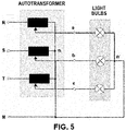
Figure 5 schematically shows an electrical circuit by way of example in which the system for measuring according to the preferred embodiment of the present invention is applied. - The method and system for measuring disclosed in the present invention are based on the calculation of a magnitude herein referred to as "imbalance power vector" (
S u). It is of a vector magnitude, i.e., it is defined in a three-dimensional space and has modulus, direction and sense. The modulus is always equal to the value of the imbalance power Su, in systems with both balanced voltages and unbalanced voltages. -
Figures 1 and 2 depict a graphic representation and block diagram representation, respectively, of the imbalance power vector and the relationships with its various components. - From the viewpoint of practical usefulness, two main components of the imbalance power vector:
S ui andS uv, are distinguished first. The first component,S ui, measures the exclusive effects of load imbalances
S uiv); this component of the imbalance power vector is represented in the plane defined by coordinate axesp ,q . Therefore, plane (p ,q ) constitutes the joint domain of load and voltage imbalances. The second component,S uv, of the imbalance power vector determines the exclusive effect of voltage imbalances and is represented on axis z (domain of voltage imbalances), orthogonal to plane (p ,q ). - It must be noted that the component

A u ) of the prior art, a magnitude which measures the exclusive effects of load imbalances, given that superscript b indicates that voltages are balanced and therefore there is no effect of voltage imbalance. - Finally, vector
S uvT, the vector sum ofS uiv andS uv, defines the total effect of voltage imbalances on the electrical grid being studied. - The imbalance power vector and its components allow obtaining quality factors offering information about the effects of imbalances on electrical grids, assessing the exclusive load imbalance or the exclusive voltage imbalance with respect to the total imbalance of the system, as well as the relative importance of resistive and reactive load imbalances, among others.
- Likewise, the total imbalance power in an electrical system or grid can be obtained as the modulus of the vector resulting from the vector sum of the imbalance power vectors of each of the integrating parts thereof.
- Now turning to
Figure 3 , a block diagram depicting a method according to the preferred embodiment of the present invention is shown, comprising the steps of: - Step (1): Digitally processing sampled signals obtained by means of a physical system for measuring and acquiring electrical signals, the matrices of effective values (VA1, VB1, VC1) and arguments (αA1, αB1, αC1) of the voltage at the fundamental frequency for each phase, as well as the matrices of effective values (IA1, IB1, IC1) and arguments (βA1, βB1, βC1) of the current at the fundamental frequency for each phase thereby being obtained.
- Step (2): The symmetrical components, i.e., the effective value (V + = V A1+) and the argument (α+ = αA1+) of the positive sequence voltages and the effective values of the negative sequence voltage (V- = V A1- ) and zero sequence voltage (V o = V A1o) are obtained from the matrices obtained in step (1).
- Step (3): In parallel to step (2), the active power (P A1, P B1, P C1) and reactive power (
Q A1,Q B1,Q C1) are obtained from the matrices obtained in step (1) as the real part (Re) and imaginary part (Im), respectively, of the complex powers of each phase:


- Step (4): The imbalance power vector (
S u), and its various components (S ui,S uv) are obtained from the active and reactive powers obtained in step (3) as well as from the symmetrical components obtained in step (2), according to the following expressions:


- Step (5): Finally, graphic and numerical information about the imbalance power vector, as well as values of the physical magnitudes used during the method if desired, is visually depicted on a suitable display device.
- According to the preferred embodiment of the present invention, in step (1) the electrical signals acquired by means of the physical system for measuring are the instantaneous values of voltage (vA, vB, vC) and intensity (iA, iB, ic) of the phases (A, B, C) at the point of the electrical grid where the measurement is being taken. Digital processing in turn consists of separating their components at the fundamental frequency (vA1, vB1, vC1), (iA1, iB1, iC1).
- According to an additional preferred embodiment of the present invention, the method comprises, in addition to or instead of step (5) of displaying described above, a step of emitting an alarm when the calculated value of at least one of the imbalance power vector (
S u), its componentS ui and its componentS uv exceeds a given threshold. The alarm can be of any suitable type in a specific application, for example a visual and/or acoustic alarm. The method thereby warns an operator that a voltage and/or load imbalance that may have serious effects on the electrical grid in question is taking place such that the operator can take the appropriate measures (for example cutting off the power supply to that part of the electrical grid) to protect the circuit and the apparatus connected thereto. - Now turning to
Figure 4 attached hereto, an example of a system for measuring according to a preferred embodiment of the present invention is shown. The system comprises voltage and intensity measurement sensors (8) for measuring instantaneous values of voltage and intensity; a signal conditioner (9) for adapting the secondary current of each measurement sensor (8) to the voltage applicable to analog inputs of an acquisition card (10); said acquisition card (10) converting the analog voltage and intensity signals into a series of discrete samples used as input in an acquisition module (13); a processing system (11) with a motherboard in which the acquisition card (10) is placed so that the discrete samples of the voltage and intensity signals can be exchanged with the acquisition module (13); and a touch screen (12) acting as the display device, connected to a display module (18) for visually presenting at least one value calculated by the system for measuring: for example voltages, intensities, active and reactive powers, symmetrical components, imbalance power vector and its components, in modulus and argument form, in addition to the graphic representation thereof. - In addition, the system for measuring according to the preferred embodiment of the present invention also comprises the following modules:
- an acquisition module (13) configured for acquiring the instantaneous values of voltage (vA, vB, vC) and intensity (iA, iB, ic) of the phases (A, B, C) at a point of the electrical grid and separating the components thereof at the fundamental frequency (vA1, vB1, vC1), (iA1, iB1, iC1);
- an analysis module (14) obtaining effective values (VA1, VB1, VC1) and arguments (αA1, αB1, αC1) of the phase voltages at the fundamental frequency, as well as effective values (IA1, IB1, IC1) and arguments (βA1, βB1, βC1) of the phase currents at the fundamental frequency of the electrical grid, from the samples acquired in the preceding module;
- a symmetrical module (15) obtaining the effective value (V + = V A1+) and the argument (α+ = αA1+) of the positive sequence voltages and the effective values of the negative sequence voltage (V - = V A1- ) and zero sequence voltage (V o = V A1o) from the results of the preceding module;
- an active and reactive power module (16) in charge of obtaining the active power (P A1, P B1, P C1) and reactive power (
Q A1,Q B1,Q C1) of each of the phases at the fundamental frequency for each type of topology of the electrical installation; - an imbalance power vector module (17) in charge of obtaining the value of the imbalance power vector (
S u) and its components, according to the following equations:


- a display module (18) in charge of visually depicting on a screen at least the calculated value of the imbalance power vector, and optionally its graphic representation and the values of other physical magnitudes, such as: effective values of voltages and intensities; active and reactive powers for each phase; symmetrical components at the fundamental frequency, etc.
- According to an additional embodiment of the present invention, the system comprises, in addition to or instead of the display module (18), an alarm module configured for emitting an alarm when the calculated value of at least one of the imbalance power vector (
S u), its componentS ui and its componentS uv exceeds a given threshold. As mentioned above, this allows notifying an operator that a voltage and/or load imbalance that may have serious effects on the electrical grid is taking place so that the operator may take appropriate measures to protect the circuit and the apparatus connected thereto. - A system for measuring such as the one described herein above is practically useful in a range of specific applications, such as the following in a non-limiting manner, for example:
- Measuring instruments: The use of a system for measuring according to the present invention in a measuring instrument allows separately determining the responsibility pertaining to users and electric companies in the energies put into play by the imbalances, as well as accurately measuring the value of said energies.
- Protection instruments: Protective relays for receivers and electrical installations used today to offset excitation voltage imbalances act by taking into consideration the value of the degree of imbalance of said voltages (relationship between the inverse and direct components of the voltages), without taking into account the magnitude of the energies that emerge due to said imbalances. The result is that when the degree of imbalance of the voltages reaches a given value (for example, 2% for one minute for three-phase electric motors), protective relays used today open the circuit to protect the receiver or the electrical installation, even when the energies put into play are not dangerous. Many receivers and installations therefore stop working on a number of occasions without this being strictly necessary, with the subsequent shutdown and reinstatement costs.
- By using a system for measuring according to the present invention in protective relays, it is possible to calculate the energy due to the exclusive effect of voltage imbalances and to evaluate whether dangerous values for the receivers and electrical installations are reached, such that the opening of the circuit and the subsequent disconnection takes place only when the imbalance energy may damage said receivers and installations, inefficient and untimely openings of the circuits thereby being prevented.
- Machine regulating equipment: The system for measuring according to the present invention can be incorporated in an electronic converter of the type normally used in various regulating applications, for example in regulating the speed of three-phase electric motors, controlling DFIG operation in wind turbines, etc. In wind farms, for example, voltage sags can cause very undesirable energetic effects, such as disconnection of the turbines, which is expressly prohibited under the regulations in force. The technologies that are applied today try to keep wind turbine operations running throughout the voltage sag by supplying active energy and reactive energy, without taking the imbalance energy into account. Therefore, when the sag is very unbalanced (one-phase and two-phase voltage sags) these technologies are useless and the turbine must be disconnected to prevent it from being severely damaged.
- The system disclosed herein allows accurately measuring energies corresponding to voltage imbalances separately from those caused by load imbalances, therefore providing the information required to act on the control circuit of the DFIG converter, thereby keeping the turbine running and minimizing energies caused by imbalances.
- Active filters: Active filters are used in electrical grids to compensate for the effects of imbalances and harmonic distortions. Active filters existing on the market do not distinguish between imbalance and distortion phenomena, given that they do not allow suitably measuring imbalances. An imbalance is generally considered to exist when the effective values of the line currents have a different value in each phase, even when this difference in values is due to harmonics. The system for measuring according to the present invention allows accurately knowing the causes of the imbalances, and therefore measuring its effects (energies) to effectively compensate for those imbalances.
- Electric machine maintenance: According to another embodiment of the present invention, the system for measuring disclosed herein is applied to electric machine (transformer and motor) maintenance. It is thereby possible to detect if a malfunction of the machine is due to a fault (deterioration of a winding or busbar, for example), or if, in contrast, it occurs due to supply voltage imbalances.
- To demonstrate the efficacy of the method and system according to the present invention and the advantages thereof with respect to the prior art, a comparative study between the imbalance power vector (
S u, present invention) and the imbalance power phasor (A u , prior art) was conducted. The electrical circuit shown inFigure 5 , in which three 100 W, 230 V incandescent light bulbs were installed was prepared, first supplying them with balanced voltages and then with unbalanced voltages. The supply voltage imbalance was achieved by means of a three-phase phase-variable autotransformer. - The three output (secondary) voltages of the autotransformer were adjusted to 115.4 V and the active power (P), the reactive power (Q), the imbalance power phasor (Au) and the imbalance power vector (Su) were recorded in a measuring instrument (digital wattmeter). The results are shown in Table 1 below.
- The output (secondary) voltages of the autotransformer were adjusted until the following values were reached: Van = 100 V, Vbn = 100 V and Vcn = 173.2 V (these voltages have a direct sequence component of 115.4 V, the same value as the balanced voltages in the preceding case). The obtained results are shown in Table 1 below.
Table 1: Power Summary P (W) Q (var) Au (VA) Su (VA) Balanced voltages 104.29 1.00 0.902 0.902 Unbalanced voltages 129.83 1.32 1.18 77.445 - From the results shown in Table 1 above, it can be seen that when balanced voltages were applied to the light bulbs, the primary phenomenon was the active power (P) phenomenon. The reactive power (Q) and imbalance powers (Au, Su) were negligible. The phasor (Au) and the imbalance power vector (Su) were also seen to have the same very minor values, although they are not quite nil due to the small imbalance of the light bulbs caused by small differences between them.
- It can also be seen that when unbalanced supply voltages were used, the active power increased by 25.5 W (24.5%) with respect to its value with balanced voltages, whereas the imbalance power phasor (Au) did not detect the change (its value is virtually the same with balanced and unbalanced voltages). However, the imbalance power vector (Su) did in fact detect the effect of the voltage imbalance, given that it went from 0.902 VA to 77.445 VA. This huge increment warns of the increase in active power consumption caused by the voltage imbalance. This effect could not have been detected by the imbalance power phasor (Au).
- Therefore, the usefulness and the advantages of the method of the present invention based on the imbalance power vector (Su) (magnitude introduced by the present invention) with respect to the prior art based on the imbalance power phasor (Au) are demonstrated.
- Although the present invention has been described above in reference to specific embodiments thereof, the skilled person will understand that modifications and variations can be made without departing from the scope of the present invention. For example, the skilled person may conceive of applications in addition to those mentioned hereinabove, in which the method and system for measuring electrical imbalances of the present invention can be applied.
- In addition, although preferred embodiments have been described for both the method and the system for measuring of the present invention in which the value of the imbalance power vector (
S u) and that of its components (S ui,S uv) are calculated, it must be understood that only the imbalance power vector (S u) is calculated in other possible embodiments of the present invention.
Claims (15)
- A method for measuring imbalances in an electrical grid, comprising the steps of:i) obtaining effective values (VA1, VB1, VC1) and arguments (αA1, αB1, αC1) of the phase voltages at the fundamental frequency, as well as effective values (IA1, IB1, IC1) and arguments (βA1, βB1, βC1) of the phase currents at the fundamental frequency of the electrical grid;ii) calculating the effective value (V + = V A1+) and the argument (α+ = αA1+) of the positive sequence voltages and the effective values of the negative sequence voltage (V - = V A1- ) and zero sequence voltage (V o = V A1o);iii) determining the active power (P A1, P B1, P C1) and reactive power (
Q A1,Q B1,Q C1) of each of the phases at the fundamental frequency from the values of the voltages and currents at the fundamental frequency; andiv) calculating the value of the imbalance power vector (S u) according to the following equation: a=1∠120°;j is the imaginary unit;δU = V-/V+ and δA = V0/V+ are the degrees of imbalance and asymmetry, respectively, of the phase voltages; and
p ,q ,z are the orthogonal unit vectors defining the space itself of the imbalance power vector. - The method according to claim 1, characterized in that it further comprises an initial step of acquiring instantaneous values of voltage (vA, vB, vC) and intensity (iA, iB, iC) of the phases (A, B, C) at a point of the electrical grid and separating the components thereof at the fundamental frequency (vA1, vB1, vC1), (iA1, iB1, iC1), said values being used in step i) for obtaining the effective values and arguments of the phase voltages and currents at the fundamental frequency of the electrical grid.
- The method according to any of the preceding claims, characterized in that it further comprises a step of calculating a component (
S ui) of the imbalance power vector determining the combined effects of voltage and load imbalances according to the following expression:
- The method according to any of the preceding claims, characterized in that it further comprises a step of calculating a component (
S uv) of the imbalance power vector determining the exclusive effect of voltage imbalances according to the following equation:
- The method according to any of claims 1 and 2, characterized in that it further comprises:- a step of calculating a component (
S ui) of the imbalance power vector determining the combined effects of voltage and load imbalances according to the following expression: - a step of calculating a component (
S uv) of the imbalance power vector determining the exclusive effect of voltage imbalances according to the following equation:
- The method according to claim 5, characterized in that it further comprises a step of visually presenting the calculated value of at least one of the imbalance power vector (
S u), its componentS ui and its componentS uv. - The method according to any of claims 5 and 6, characterized in that it further comprises a step of emitting an alarm when the calculated value of at least one of the imbalance power vector (
S u), its componentS ui and its componentS uv exceeds a given threshold. - A system for measuring imbalances in an electrical grid, comprising:- an analysis module (14), configured for obtaining effective values (VA1, VB1, VC1) and arguments (αA1, αB1, αC1) of the phase voltages at the fundamental frequency, as well as effective values (IA1, IB1, IC1) and arguments (βA1, βB1, βC1) of the phase currents at the fundamental frequency of the electrical grid;- a symmetrical module (15), configured for obtaining the effective value (V + = V A1+) and the argument (α+ = αA1+) of the positive sequence voltages and the effective values of the negative sequence voltage (V - = V A1- ) and zero sequence voltage (V o = V A1o);- an active and reactive power module (16), configured for obtaining the active power (P A1, P B1, P C1) and reactive power (
Q A1,Q B1,Q C1) of each of the phases at the fundamental frequency;- an imbalance power vector module (17), configured for calculating the value of the imbalance power vector (S u) according to the following equation: a=1∠120°;j is the imaginary unit;δU = V-/V+ and δA = V0/V+ are the degrees of imbalance and asymmetry, respectively, of the phase voltages; and
p ,q ,z are the orthogonal unit vectors defining the space itself of the imbalance power vector; and- an information module, configured for providing information about the calculated value of the imbalance power vector. - The system according to claim 8, characterized in that it further comprises an acquisition module (13) configured for acquiring the instantaneous values of voltage (vA, vB, vC) and intensity (iA, iB, ic) of the phases (A, B, C) at a point of the electrical grid and separating the components thereof at the fundamental frequency (vA1, vB1, vC1), (iA1, iB1, iC1), said values being used by the analysis module (14) for obtaining the effective values and arguments of the phase voltages and currents at the fundamental frequency of the electrical grid.
- The system according to any of claims 8 and 9, characterized in that the imbalance power vector module (17) is further configured for calculating a component (
S ui) of the imbalance power vector determining the combined effects of voltage and load imbalances according to the following expression:
- The system according to any of claims 8 to 10, characterized in that the imbalance power vector module (17) is further configured for calculating a component (
S uv) of the imbalance power vector determining the exclusive effect of voltage imbalances according to the following equation:
- The system according to any of claims 8 and 9, characterized in that the imbalance power vector module (17) is further configured for calculating:- a component (
S ui) of the imbalance power vector determining the combined effects of voltage and load imbalances according to the following expression: - a component (
S uv) of the imbalance power vector determining the exclusive effect of voltage imbalances according to the following equation:
- The system according to claim 12, characterized in that the information module is a display module (18) configured for visually depicting said information consisting of at least one of the calculated value and the graphic representation of said value of at least one of the calculated value of the imbalance power vector, its component
S ui and its componentS uv. - The system according to any of claims 12 and 13, characterized in that the information module is an alarm module configured for emitting an alarm when the calculated value of at least one of the imbalance power vector (
S u), its componentS ui and its componentS uv exceeds a given threshold. - The system according to any of claims 8 to 13, characterized in that it further comprises:- voltage and intensity measurement sensors (8) for measuring the instantaneous values of voltage and intensity;- a signal conditioner (9) for adapting the secondary current of each measurement sensor (8) to the voltage applicable to analog inputs of an acquisition card (10);- an acquisition card (10) converting analog signals into a series of discrete samples used as input in the acquisition module (13);- a processing system (11) connecting the acquisition card (10) with the acquisition module (13); and- a display device (12) connected with the display module (18) for visually presenting at least one value calculated by the system for measuring.
Applications Claiming Priority (2)
| Application Number | Priority Date | Filing Date | Title |
|---|---|---|---|
| ES201431822A ES2544902B8 (en) | 2014-12-11 | 2014-12-11 | Method and system for measuring imbalances in a power grid |
| PCT/ES2015/070879 WO2016092133A1 (en) | 2014-12-11 | 2015-12-04 | Method and system for measuring imbalances in an electrical grid |
Publications (3)
| Publication Number | Publication Date |
|---|---|
| EP3232207A1 true EP3232207A1 (en) | 2017-10-18 |
| EP3232207A4 EP3232207A4 (en) | 2018-09-12 |
| EP3232207B1 EP3232207B1 (en) | 2019-10-02 |
Family
ID=54011353
Family Applications (1)
| Application Number | Title | Priority Date | Filing Date |
|---|---|---|---|
| EP15867012.5A Not-in-force EP3232207B1 (en) | 2014-12-11 | 2015-12-04 | Method and system for measuring imbalances in an electrical grid |
Country Status (4)
| Country | Link |
|---|---|
| US (1) | US20170343591A1 (en) |
| EP (1) | EP3232207B1 (en) |
| ES (1) | ES2544902B8 (en) |
| WO (1) | WO2016092133A1 (en) |
Families Citing this family (3)
| Publication number | Priority date | Publication date | Assignee | Title |
|---|---|---|---|---|
| CN108414821B (en) * | 2018-05-17 | 2023-05-19 | 福建奥通迈胜电力科技有限公司 | Distribution transformer low-voltage side voltage three-phase imbalance evaluation method based on zero sequence voltage |
| CN112003306B (en) * | 2020-07-21 | 2022-09-09 | 中国电力科学研究院有限公司 | A method and system for determining the unbalance degree of three-phase current in a wind farm |
| CN112730971B (en) * | 2020-12-17 | 2023-10-24 | 广州发展电力科技有限公司 | Reactive power measurement system |
Family Cites Families (9)
| Publication number | Priority date | Publication date | Assignee | Title |
|---|---|---|---|---|
| US6246332B1 (en) * | 1998-11-18 | 2001-06-12 | Abb Power T&D Company Inc. | System and method for detecting voltage and current imbalance in an electrical energy supply |
| ES2215467B1 (en) * | 2002-09-13 | 2005-12-16 | Consejo Sup. De Investig. Cientificas | APPARATUS AND METHOD OF MEASUREMENT OF ELECTRICAL MAGNITUDES IN A THREE PHASE NETWORK. |
| ES2316280B1 (en) * | 2007-04-30 | 2010-01-29 | Universidad Politecnica De Valencia | PROCEDURE AND SYSTEM OF PUTTING INTO PRACTICE FOR THE MEASUREMENT OF UNBALANCE POWER IN ELECTRICAL INSTALLATIONS, AS WELL AS THE DEVICE FOR CALIBRATION. |
| ES2342528A1 (en) * | 2008-07-18 | 2010-07-07 | Universidad Politecnica De Valencia | Method and system for calculating the reactive power in disturbed three-phase networks |
| ES2333838B2 (en) * | 2009-07-09 | 2011-02-07 | Universidad Politecnica De Valencia | PROCEDURE FOR THE COMPENSATION OF UNBALANCES IN THE SUPPLY OF ELECTRICAL ENERGY, AS WELL AS THE COMPENSATING DEVICE FOR ASSUMPTION IN PRACTICE. |
| ES2423828B2 (en) * | 2011-05-27 | 2014-02-11 | Universidad Politécnica De Valencia | PROCEDURE AND DEVICE OF ACTIVE CALIBRATION OF THE FASOR POWER OF UNQUALIBILITY OF ELECTRICAL INSTALLATIONS |
| CN102331535B (en) * | 2011-06-09 | 2014-06-04 | 郝玉山 | Alternating current physical quantity measuring device and method as well as data acquisition device and method |
| CN102435869B (en) * | 2011-08-26 | 2014-03-05 | 东北大学 | Experimental device for automatic regulation and compensation of three-phase unbalanced load and control method thereof |
| FR2981751B1 (en) * | 2011-10-19 | 2020-04-17 | Schneider Electric Industries Sas | METHOD AND DEVICE FOR ANALYZING THE QUALITY OF ELECTRICAL ENERGY IN A THREE-PHASE ELECTRICAL NETWORK |
-
2014
- 2014-12-11 ES ES201431822A patent/ES2544902B8/en active Active
-
2015
- 2015-12-04 WO PCT/ES2015/070879 patent/WO2016092133A1/en not_active Ceased
- 2015-12-04 EP EP15867012.5A patent/EP3232207B1/en not_active Not-in-force
- 2015-12-04 US US15/534,564 patent/US20170343591A1/en not_active Abandoned
Also Published As
| Publication number | Publication date |
|---|---|
| EP3232207B1 (en) | 2019-10-02 |
| ES2544902A1 (en) | 2015-09-04 |
| ES2544902B8 (en) | 2016-02-12 |
| WO2016092133A1 (en) | 2016-06-16 |
| EP3232207A4 (en) | 2018-09-12 |
| ES2544902B2 (en) | 2016-01-04 |
| US20170343591A1 (en) | 2017-11-30 |
Similar Documents
| Publication | Publication Date | Title |
|---|---|---|
| US8823307B2 (en) | System for detecting internal winding faults of a synchronous generator, computer program product and method | |
| Azzouz et al. | Resilience enhancement of microgrids with inverter-interfaced DGs by enabling faulty phase selection | |
| Hooshyar et al. | Microgrid protection | |
| Khederzadeh et al. | Impact of VSC-based multiline FACTS controllers on distance protection of transmission lines | |
| US20190245343A1 (en) | Method to detect utility disturbance and fault direction | |
| US7852605B2 (en) | Arc-flash hazard protection system for three-phase electrical distribution system | |
| JP5926419B1 (en) | Phase loss detector | |
| Saleh et al. | Experimental assessment of ground fault protection in frequency-selective grounded systems fed by a single transformer | |
| Isa et al. | Evaluation on non-detection zone of passive islanding detection techniques for synchronous distributed generation | |
| EP3232207B1 (en) | Method and system for measuring imbalances in an electrical grid | |
| JP3167620B2 (en) | Harmonic outflow evaluation device | |
| Mumtaz et al. | Incipient fault detection in active-distribution networks based on Time-varying Kalman Filter | |
| Ghorbani et al. | Modeling of Digital Distance Relay in EMTPWorks Considering Protective Zones and Trip Characteristics | |
| Mati et al. | A new framework of numerical distance relay using LabVIEW | |
| Dawood et al. | Fuzzy logic based scheme for directional earth fault detection and classification | |
| Nicorescu et al. | On the impact of winding selection of current instrument transformers for PMU measurements | |
| JP2011045215A (en) | Ground fault distance protective relay device | |
| Kamble et al. | Classification of voltage sags in distribution systems due to short circuit faults | |
| Kaveh et al. | Performance evaluation of overcurrent and directional overcurrent relays under harmonic and imbalance conditions: a case study of a 132/20 kV substation | |
| US20250279255A1 (en) | Protection through a power transformer using compensated voltages and currents | |
| Soliman et al. | Power systems fault type identification based on Park's transformation algorithm | |
| Wang et al. | Network-Integrated DSP-based adaptive high impedance ground fault feeder protection | |
| Talebi et al. | Substation testing and commissioning: power transformer through fault test | |
| Supriyanto et al. | The Test Bench for Simulation Phase Fault and Ground Fault Analysis Protection Concept Using Symmetrical Components | |
| Biller et al. | Selective Protection Relaying in the Presence of Distributed Generation and Closed-Ring Structures |
Legal Events
| Date | Code | Title | Description |
|---|---|---|---|
| STAA | Information on the status of an ep patent application or granted ep patent |
Free format text: STATUS: THE INTERNATIONAL PUBLICATION HAS BEEN MADE |
|
| PUAI | Public reference made under article 153(3) epc to a published international application that has entered the european phase |
Free format text: ORIGINAL CODE: 0009012 |
|
| STAA | Information on the status of an ep patent application or granted ep patent |
Free format text: STATUS: REQUEST FOR EXAMINATION WAS MADE |
|
| 17P | Request for examination filed |
Effective date: 20170619 |
|
| AK | Designated contracting states |
Kind code of ref document: A1 Designated state(s): AL AT BE BG CH CY CZ DE DK EE ES FI FR GB GR HR HU IE IS IT LI LT LU LV MC MK MT NL NO PL PT RO RS SE SI SK SM TR |
|
| AX | Request for extension of the european patent |
Extension state: BA ME |
|
| DAV | Request for validation of the european patent (deleted) | ||
| DAX | Request for extension of the european patent (deleted) | ||
| A4 | Supplementary search report drawn up and despatched |
Effective date: 20180809 |
|
| RIC1 | Information provided on ipc code assigned before grant |
Ipc: G01R 21/06 20060101AFI20180804BHEP Ipc: G01R 21/00 20060101ALI20180804BHEP |
|
| GRAP | Despatch of communication of intention to grant a patent |
Free format text: ORIGINAL CODE: EPIDOSNIGR1 |
|
| STAA | Information on the status of an ep patent application or granted ep patent |
Free format text: STATUS: GRANT OF PATENT IS INTENDED |
|
| INTG | Intention to grant announced |
Effective date: 20190503 |
|
| GRAS | Grant fee paid |
Free format text: ORIGINAL CODE: EPIDOSNIGR3 |
|
| GRAA | (expected) grant |
Free format text: ORIGINAL CODE: 0009210 |
|
| STAA | Information on the status of an ep patent application or granted ep patent |
Free format text: STATUS: THE PATENT HAS BEEN GRANTED |
|
| AK | Designated contracting states |
Kind code of ref document: B1 Designated state(s): AL AT BE BG CH CY CZ DE DK EE ES FI FR GB GR HR HU IE IS IT LI LT LU LV MC MK MT NL NO PL PT RO RS SE SI SK SM TR |
|
| REG | Reference to a national code |
Ref country code: GB Ref legal event code: FG4D |
|
| REG | Reference to a national code |
Ref country code: CH Ref legal event code: EP Ref country code: AT Ref legal event code: REF Ref document number: 1186786 Country of ref document: AT Kind code of ref document: T Effective date: 20191015 |
|
| REG | Reference to a national code |
Ref country code: DE Ref legal event code: R096 Ref document number: 602015039282 Country of ref document: DE |
|
| REG | Reference to a national code |
Ref country code: IE Ref legal event code: FG4D |
|
| REG | Reference to a national code |
Ref country code: NL Ref legal event code: MP Effective date: 20191002 |
|
| REG | Reference to a national code |
Ref country code: LT Ref legal event code: MG4D |
|
| REG | Reference to a national code |
Ref country code: AT Ref legal event code: MK05 Ref document number: 1186786 Country of ref document: AT Kind code of ref document: T Effective date: 20191002 |
|
| PG25 | Lapsed in a contracting state [announced via postgrant information from national office to epo] |
Ref country code: LT Free format text: LAPSE BECAUSE OF FAILURE TO SUBMIT A TRANSLATION OF THE DESCRIPTION OR TO PAY THE FEE WITHIN THE PRESCRIBED TIME-LIMIT Effective date: 20191002 Ref country code: BG Free format text: LAPSE BECAUSE OF FAILURE TO SUBMIT A TRANSLATION OF THE DESCRIPTION OR TO PAY THE FEE WITHIN THE PRESCRIBED TIME-LIMIT Effective date: 20200102 Ref country code: NO Free format text: LAPSE BECAUSE OF FAILURE TO SUBMIT A TRANSLATION OF THE DESCRIPTION OR TO PAY THE FEE WITHIN THE PRESCRIBED TIME-LIMIT Effective date: 20200102 Ref country code: SE Free format text: LAPSE BECAUSE OF FAILURE TO SUBMIT A TRANSLATION OF THE DESCRIPTION OR TO PAY THE FEE WITHIN THE PRESCRIBED TIME-LIMIT Effective date: 20191002 Ref country code: PT Free format text: LAPSE BECAUSE OF FAILURE TO SUBMIT A TRANSLATION OF THE DESCRIPTION OR TO PAY THE FEE WITHIN THE PRESCRIBED TIME-LIMIT Effective date: 20200203 Ref country code: AT Free format text: LAPSE BECAUSE OF FAILURE TO SUBMIT A TRANSLATION OF THE DESCRIPTION OR TO PAY THE FEE WITHIN THE PRESCRIBED TIME-LIMIT Effective date: 20191002 Ref country code: FI Free format text: LAPSE BECAUSE OF FAILURE TO SUBMIT A TRANSLATION OF THE DESCRIPTION OR TO PAY THE FEE WITHIN THE PRESCRIBED TIME-LIMIT Effective date: 20191002 Ref country code: LV Free format text: LAPSE BECAUSE OF FAILURE TO SUBMIT A TRANSLATION OF THE DESCRIPTION OR TO PAY THE FEE WITHIN THE PRESCRIBED TIME-LIMIT Effective date: 20191002 Ref country code: NL Free format text: LAPSE BECAUSE OF FAILURE TO SUBMIT A TRANSLATION OF THE DESCRIPTION OR TO PAY THE FEE WITHIN THE PRESCRIBED TIME-LIMIT Effective date: 20191002 Ref country code: ES Free format text: LAPSE BECAUSE OF FAILURE TO SUBMIT A TRANSLATION OF THE DESCRIPTION OR TO PAY THE FEE WITHIN THE PRESCRIBED TIME-LIMIT Effective date: 20191002 Ref country code: PL Free format text: LAPSE BECAUSE OF FAILURE TO SUBMIT A TRANSLATION OF THE DESCRIPTION OR TO PAY THE FEE WITHIN THE PRESCRIBED TIME-LIMIT Effective date: 20191002 |
|
| PG25 | Lapsed in a contracting state [announced via postgrant information from national office to epo] |
Ref country code: IS Free format text: LAPSE BECAUSE OF FAILURE TO SUBMIT A TRANSLATION OF THE DESCRIPTION OR TO PAY THE FEE WITHIN THE PRESCRIBED TIME-LIMIT Effective date: 20200224 Ref country code: CZ Free format text: LAPSE BECAUSE OF FAILURE TO SUBMIT A TRANSLATION OF THE DESCRIPTION OR TO PAY THE FEE WITHIN THE PRESCRIBED TIME-LIMIT Effective date: 20191002 Ref country code: HR Free format text: LAPSE BECAUSE OF FAILURE TO SUBMIT A TRANSLATION OF THE DESCRIPTION OR TO PAY THE FEE WITHIN THE PRESCRIBED TIME-LIMIT Effective date: 20191002 Ref country code: RS Free format text: LAPSE BECAUSE OF FAILURE TO SUBMIT A TRANSLATION OF THE DESCRIPTION OR TO PAY THE FEE WITHIN THE PRESCRIBED TIME-LIMIT Effective date: 20191002 |
|
| PG25 | Lapsed in a contracting state [announced via postgrant information from national office to epo] |
Ref country code: AL Free format text: LAPSE BECAUSE OF FAILURE TO SUBMIT A TRANSLATION OF THE DESCRIPTION OR TO PAY THE FEE WITHIN THE PRESCRIBED TIME-LIMIT Effective date: 20191002 |
|
| REG | Reference to a national code |
Ref country code: DE Ref legal event code: R119 Ref document number: 602015039282 Country of ref document: DE |
|
| PG2D | Information on lapse in contracting state deleted |
Ref country code: IS |
|
| PG25 | Lapsed in a contracting state [announced via postgrant information from national office to epo] |
Ref country code: RO Free format text: LAPSE BECAUSE OF FAILURE TO SUBMIT A TRANSLATION OF THE DESCRIPTION OR TO PAY THE FEE WITHIN THE PRESCRIBED TIME-LIMIT Effective date: 20191002 Ref country code: EE Free format text: LAPSE BECAUSE OF FAILURE TO SUBMIT A TRANSLATION OF THE DESCRIPTION OR TO PAY THE FEE WITHIN THE PRESCRIBED TIME-LIMIT Effective date: 20191002 Ref country code: DK Free format text: LAPSE BECAUSE OF FAILURE TO SUBMIT A TRANSLATION OF THE DESCRIPTION OR TO PAY THE FEE WITHIN THE PRESCRIBED TIME-LIMIT Effective date: 20191002 Ref country code: IS Free format text: LAPSE BECAUSE OF FAILURE TO SUBMIT A TRANSLATION OF THE DESCRIPTION OR TO PAY THE FEE WITHIN THE PRESCRIBED TIME-LIMIT Effective date: 20200202 |
|
| REG | Reference to a national code |
Ref country code: CH Ref legal event code: PL |
|
| PLBE | No opposition filed within time limit |
Free format text: ORIGINAL CODE: 0009261 |
|
| STAA | Information on the status of an ep patent application or granted ep patent |
Free format text: STATUS: NO OPPOSITION FILED WITHIN TIME LIMIT |
|
| REG | Reference to a national code |
Ref country code: BE Ref legal event code: MM Effective date: 20191231 |
|
| PG25 | Lapsed in a contracting state [announced via postgrant information from national office to epo] |
Ref country code: MC Free format text: LAPSE BECAUSE OF FAILURE TO SUBMIT A TRANSLATION OF THE DESCRIPTION OR TO PAY THE FEE WITHIN THE PRESCRIBED TIME-LIMIT Effective date: 20191002 Ref country code: SM Free format text: LAPSE BECAUSE OF FAILURE TO SUBMIT A TRANSLATION OF THE DESCRIPTION OR TO PAY THE FEE WITHIN THE PRESCRIBED TIME-LIMIT Effective date: 20191002 Ref country code: IT Free format text: LAPSE BECAUSE OF FAILURE TO SUBMIT A TRANSLATION OF THE DESCRIPTION OR TO PAY THE FEE WITHIN THE PRESCRIBED TIME-LIMIT Effective date: 20191002 Ref country code: SK Free format text: LAPSE BECAUSE OF FAILURE TO SUBMIT A TRANSLATION OF THE DESCRIPTION OR TO PAY THE FEE WITHIN THE PRESCRIBED TIME-LIMIT Effective date: 20191002 |
|
| 26N | No opposition filed |
Effective date: 20200703 |
|
| GBPC | Gb: european patent ceased through non-payment of renewal fee |
Effective date: 20200102 |
|
| PG25 | Lapsed in a contracting state [announced via postgrant information from national office to epo] |
Ref country code: LU Free format text: LAPSE BECAUSE OF NON-PAYMENT OF DUE FEES Effective date: 20191204 Ref country code: GB Free format text: LAPSE BECAUSE OF NON-PAYMENT OF DUE FEES Effective date: 20200102 Ref country code: DE Free format text: LAPSE BECAUSE OF NON-PAYMENT OF DUE FEES Effective date: 20200701 Ref country code: FR Free format text: LAPSE BECAUSE OF NON-PAYMENT OF DUE FEES Effective date: 20191231 Ref country code: IE Free format text: LAPSE BECAUSE OF NON-PAYMENT OF DUE FEES Effective date: 20191204 |
|
| PG25 | Lapsed in a contracting state [announced via postgrant information from national office to epo] |
Ref country code: LI Free format text: LAPSE BECAUSE OF NON-PAYMENT OF DUE FEES Effective date: 20191231 Ref country code: CH Free format text: LAPSE BECAUSE OF NON-PAYMENT OF DUE FEES Effective date: 20191231 Ref country code: BE Free format text: LAPSE BECAUSE OF NON-PAYMENT OF DUE FEES Effective date: 20191231 Ref country code: SI Free format text: LAPSE BECAUSE OF FAILURE TO SUBMIT A TRANSLATION OF THE DESCRIPTION OR TO PAY THE FEE WITHIN THE PRESCRIBED TIME-LIMIT Effective date: 20191002 |
|
| PG25 | Lapsed in a contracting state [announced via postgrant information from national office to epo] |
Ref country code: CY Free format text: LAPSE BECAUSE OF FAILURE TO SUBMIT A TRANSLATION OF THE DESCRIPTION OR TO PAY THE FEE WITHIN THE PRESCRIBED TIME-LIMIT Effective date: 20191002 |
|
| PG25 | Lapsed in a contracting state [announced via postgrant information from national office to epo] |
Ref country code: GR Free format text: LAPSE BECAUSE OF FAILURE TO SUBMIT A TRANSLATION OF THE DESCRIPTION OR TO PAY THE FEE WITHIN THE PRESCRIBED TIME-LIMIT Effective date: 20191002 |
|
| PG25 | Lapsed in a contracting state [announced via postgrant information from national office to epo] |
Ref country code: MT Free format text: LAPSE BECAUSE OF FAILURE TO SUBMIT A TRANSLATION OF THE DESCRIPTION OR TO PAY THE FEE WITHIN THE PRESCRIBED TIME-LIMIT Effective date: 20191002 Ref country code: HU Free format text: LAPSE BECAUSE OF FAILURE TO SUBMIT A TRANSLATION OF THE DESCRIPTION OR TO PAY THE FEE WITHIN THE PRESCRIBED TIME-LIMIT; INVALID AB INITIO Effective date: 20151204 |
|
| PG25 | Lapsed in a contracting state [announced via postgrant information from national office to epo] |
Ref country code: TR Free format text: LAPSE BECAUSE OF FAILURE TO SUBMIT A TRANSLATION OF THE DESCRIPTION OR TO PAY THE FEE WITHIN THE PRESCRIBED TIME-LIMIT Effective date: 20191002 |
|
| PG25 | Lapsed in a contracting state [announced via postgrant information from national office to epo] |
Ref country code: MK Free format text: LAPSE BECAUSE OF FAILURE TO SUBMIT A TRANSLATION OF THE DESCRIPTION OR TO PAY THE FEE WITHIN THE PRESCRIBED TIME-LIMIT Effective date: 20191002 |