EP3232033A2 - Turbocharger with rotary bypass valve operable to selectively configure the turbine volute as single-scroll or twin-scroll - Google Patents
Turbocharger with rotary bypass valve operable to selectively configure the turbine volute as single-scroll or twin-scroll Download PDFInfo
- Publication number
- EP3232033A2 EP3232033A2 EP16199903.2A EP16199903A EP3232033A2 EP 3232033 A2 EP3232033 A2 EP 3232033A2 EP 16199903 A EP16199903 A EP 16199903A EP 3232033 A2 EP3232033 A2 EP 3232033A2
- Authority
- EP
- European Patent Office
- Prior art keywords
- bypass
- valve
- exhaust gas
- scroll
- valve seat
- Prior art date
- Legal status (The legal status is an assumption and is not a legal conclusion. Google has not performed a legal analysis and makes no representation as to the accuracy of the status listed.)
- Granted
Links
- 238000004891 communication Methods 0.000 claims description 5
- 239000012530 fluid Substances 0.000 claims description 2
- 230000037361 pathway Effects 0.000 description 9
- 238000002955 isolation Methods 0.000 description 5
- 230000000694 effects Effects 0.000 description 3
- 230000009286 beneficial effect Effects 0.000 description 2
- 238000005266 casting Methods 0.000 description 2
- 238000000034 method Methods 0.000 description 2
- 238000012986 modification Methods 0.000 description 2
- 230000004048 modification Effects 0.000 description 2
- 230000008569 process Effects 0.000 description 2
- 238000011144 upstream manufacturing Methods 0.000 description 2
- 238000000429 assembly Methods 0.000 description 1
- 230000008901 benefit Effects 0.000 description 1
- 238000002485 combustion reaction Methods 0.000 description 1
- 238000003754 machining Methods 0.000 description 1
- 239000000463 material Substances 0.000 description 1
- 230000007246 mechanism Effects 0.000 description 1
- 230000001105 regulatory effect Effects 0.000 description 1
Images




Classifications
-
- F—MECHANICAL ENGINEERING; LIGHTING; HEATING; WEAPONS; BLASTING
- F02—COMBUSTION ENGINES; HOT-GAS OR COMBUSTION-PRODUCT ENGINE PLANTS
- F02B—INTERNAL-COMBUSTION PISTON ENGINES; COMBUSTION ENGINES IN GENERAL
- F02B37/00—Engines characterised by provision of pumps driven at least for part of the time by exhaust
- F02B37/12—Control of the pumps
- F02B37/18—Control of the pumps by bypassing exhaust from the inlet to the outlet of turbine or to the atmosphere
- F02B37/183—Arrangements of bypass valves or actuators therefor
-
- F—MECHANICAL ENGINEERING; LIGHTING; HEATING; WEAPONS; BLASTING
- F02—COMBUSTION ENGINES; HOT-GAS OR COMBUSTION-PRODUCT ENGINE PLANTS
- F02B—INTERNAL-COMBUSTION PISTON ENGINES; COMBUSTION ENGINES IN GENERAL
- F02B37/00—Engines characterised by provision of pumps driven at least for part of the time by exhaust
- F02B37/12—Control of the pumps
- F02B37/22—Control of the pumps by varying cross-section of exhaust passages or air passages, e.g. by throttling turbine inlets or outlets or by varying effective number of guide conduits
-
- F—MECHANICAL ENGINEERING; LIGHTING; HEATING; WEAPONS; BLASTING
- F01—MACHINES OR ENGINES IN GENERAL; ENGINE PLANTS IN GENERAL; STEAM ENGINES
- F01D—NON-POSITIVE DISPLACEMENT MACHINES OR ENGINES, e.g. STEAM TURBINES
- F01D17/00—Regulating or controlling by varying flow
- F01D17/10—Final actuators
- F01D17/105—Final actuators by passing part of the fluid
-
- F—MECHANICAL ENGINEERING; LIGHTING; HEATING; WEAPONS; BLASTING
- F01—MACHINES OR ENGINES IN GENERAL; ENGINE PLANTS IN GENERAL; STEAM ENGINES
- F01D—NON-POSITIVE DISPLACEMENT MACHINES OR ENGINES, e.g. STEAM TURBINES
- F01D25/00—Component parts, details, or accessories, not provided for in, or of interest apart from, other groups
- F01D25/24—Casings; Casing parts, e.g. diaphragms, casing fastenings
-
- F—MECHANICAL ENGINEERING; LIGHTING; HEATING; WEAPONS; BLASTING
- F01—MACHINES OR ENGINES IN GENERAL; ENGINE PLANTS IN GENERAL; STEAM ENGINES
- F01D—NON-POSITIVE DISPLACEMENT MACHINES OR ENGINES, e.g. STEAM TURBINES
- F01D5/00—Blades; Blade-carrying members; Heating, heat-insulating, cooling or antivibration means on the blades or the members
- F01D5/02—Blade-carrying members, e.g. rotors
-
- F—MECHANICAL ENGINEERING; LIGHTING; HEATING; WEAPONS; BLASTING
- F02—COMBUSTION ENGINES; HOT-GAS OR COMBUSTION-PRODUCT ENGINE PLANTS
- F02B—INTERNAL-COMBUSTION PISTON ENGINES; COMBUSTION ENGINES IN GENERAL
- F02B37/00—Engines characterised by provision of pumps driven at least for part of the time by exhaust
- F02B37/02—Gas passages between engine outlet and pump drive, e.g. reservoirs
- F02B37/025—Multiple scrolls or multiple gas passages guiding the gas to the pump drive
-
- F—MECHANICAL ENGINEERING; LIGHTING; HEATING; WEAPONS; BLASTING
- F02—COMBUSTION ENGINES; HOT-GAS OR COMBUSTION-PRODUCT ENGINE PLANTS
- F02B—INTERNAL-COMBUSTION PISTON ENGINES; COMBUSTION ENGINES IN GENERAL
- F02B37/00—Engines characterised by provision of pumps driven at least for part of the time by exhaust
- F02B37/12—Control of the pumps
- F02B37/18—Control of the pumps by bypassing exhaust from the inlet to the outlet of turbine or to the atmosphere
- F02B37/183—Arrangements of bypass valves or actuators therefor
- F02B37/186—Arrangements of actuators or linkage for bypass valves
-
- F—MECHANICAL ENGINEERING; LIGHTING; HEATING; WEAPONS; BLASTING
- F02—COMBUSTION ENGINES; HOT-GAS OR COMBUSTION-PRODUCT ENGINE PLANTS
- F02C—GAS-TURBINE PLANTS; AIR INTAKES FOR JET-PROPULSION PLANTS; CONTROLLING FUEL SUPPLY IN AIR-BREATHING JET-PROPULSION PLANTS
- F02C6/00—Plural gas-turbine plants; Combinations of gas-turbine plants with other apparatus; Adaptations of gas-turbine plants for special use
- F02C6/04—Gas-turbine plants providing heated or pressurised working fluid for other apparatus, e.g. without mechanical power output
- F02C6/10—Gas-turbine plants providing heated or pressurised working fluid for other apparatus, e.g. without mechanical power output supplying working fluid to a user, e.g. a chemical process, which returns working fluid to a turbine of the plant
- F02C6/12—Turbochargers, i.e. plants for augmenting mechanical power output of internal-combustion piston engines by increase of charge pressure
-
- F—MECHANICAL ENGINEERING; LIGHTING; HEATING; WEAPONS; BLASTING
- F05—INDEXING SCHEMES RELATING TO ENGINES OR PUMPS IN VARIOUS SUBCLASSES OF CLASSES F01-F04
- F05D—INDEXING SCHEME FOR ASPECTS RELATING TO NON-POSITIVE-DISPLACEMENT MACHINES OR ENGINES, GAS-TURBINES OR JET-PROPULSION PLANTS
- F05D2220/00—Application
- F05D2220/40—Application in turbochargers
-
- F—MECHANICAL ENGINEERING; LIGHTING; HEATING; WEAPONS; BLASTING
- F05—INDEXING SCHEMES RELATING TO ENGINES OR PUMPS IN VARIOUS SUBCLASSES OF CLASSES F01-F04
- F05D—INDEXING SCHEME FOR ASPECTS RELATING TO NON-POSITIVE-DISPLACEMENT MACHINES OR ENGINES, GAS-TURBINES OR JET-PROPULSION PLANTS
- F05D2260/00—Function
- F05D2260/60—Fluid transfer
- F05D2260/606—Bypassing the fluid
-
- Y—GENERAL TAGGING OF NEW TECHNOLOGICAL DEVELOPMENTS; GENERAL TAGGING OF CROSS-SECTIONAL TECHNOLOGIES SPANNING OVER SEVERAL SECTIONS OF THE IPC; TECHNICAL SUBJECTS COVERED BY FORMER USPC CROSS-REFERENCE ART COLLECTIONS [XRACs] AND DIGESTS
- Y02—TECHNOLOGIES OR APPLICATIONS FOR MITIGATION OR ADAPTATION AGAINST CLIMATE CHANGE
- Y02T—CLIMATE CHANGE MITIGATION TECHNOLOGIES RELATED TO TRANSPORTATION
- Y02T10/00—Road transport of goods or passengers
- Y02T10/10—Internal combustion engine [ICE] based vehicles
- Y02T10/12—Improving ICE efficiencies
Definitions
- the present disclosure relates to exhaust gas-driven turbochargers, and particularly to turbochargers having a twin-scroll turbine volute for preserving an advantageous exhaust gas pulse-effect at low engine speeds.
- a turbocharger that is selectively configurable in either a single-scroll or twin-scroll configuration, and the mechanism for switching between these configurations is integrated into an annular bypass valve for the turbine.
- a turbocharger comprises a compressor wheel mounted within a compressor housing, and a turbine housing defining a bore extending along a longitudinal axis and defining a sector-divided volute comprising first and second scrolls each occupying about 180 degrees of a full circumference about the longitudinal axis, the turbine housing further defining first and second exhaust gas inlets that are separate from each other and respectively feed exhaust gas into the first and second scrolls.
- a turbine wheel is disposed in the turbine housing.
- the turbine housing defines an annular bypass passage surrounding the bore and arranged to allow exhaust gas in the chamber to bypass the turbine wheel, wherein a portion of the annular bypass passage adjacent the first and second scrolls is sector-divided by a pair of dividing walls located within the bypass passage and respectively disposed on diametrically opposite sides of the bore, the dividing walls dividing the portion of the bypass passage into half annular first and second bypass sectors.
- Each dividing wall defines a through-hole establishing fluid communication between the bypass sectors.
- the first scroll is connected to the first bypass sector to allow exhaust gas to pass from the first scroll to the first bypass sector
- the second scroll is connected to the second bypass sector to allow exhaust gas to pass from the second scroll to the second bypass sector.
- An annular bypass valve is disposed in an annular portion of the bypass passage and operable when opened to allow exhaust gas to bypass the turbine wheel, the bypass valve comprising a fixed annular valve seat and an annular valve rotor that is disposed against the valve seat and is rotatable about the longitudinal axis.
- the valve seat defines a plurality of valve seat orifices extending axially therethrough and the valve rotor defines a plurality of valve rotor orifices extending axially therethrough, forming a plurality of orifice pairs each comprising a valve seat orifice and a corresponding valve rotor orifice, the orifices of the orifice pairs being arranged to overlap in some rotational positions of the valve rotor so as to create bypass flow passages formed by aligned portions of the valve seat orifices and valve rotor orifices,.
- the valve rotor includes a pair of valve members structured and arranged to respectively close the through-holes in the dividing walls in a fully closed rotational position of the valve rotor so as isolate the first and second bypass sectors from each other, the bypass flow passages also being closed in the fully closed position. In this configuration, separate streams of exhaust gas are fed to the first and second scrolls and remain separate up to the entrance to the turbine wheel.
- the valve rotor is structured such that in a first intermediate position displaced from the fully closed position the valve members open the through-holes in the dividing walls so as to permit exhaust gas to flow between the first and second bypass sectors while the bypass flow passages remain closed. Accordingly, a portion of an exhaust gas pulse entering the first exhaust gas inlet into the first scroll can flow into the associated first bypass sector, through the dividing wall holes into the second bypass sector and from there into the second scroll and then to the turbine wheel. Although this secondary pathway to the turbine wheel is circuitous and not as efficient as the direct path from the first scroll to the wheel, it nevertheless establishes a secondary pathway that increases the total flow area to the turbine wheel. Likewise, a portion of an exhaust gas pulse into the second scroll can find a secondary pathway to the wheel via the second bypass sector to the first bypass sector and through to the first scroll and then to the wheel.
- the turbine can be placed in a configuration that is effectively single-scroll, while the bypass valve remains closed to bypass flow.
- the valve rotor can be rotated to the fully open position.
- the valve rotor is rotatable to a second intermediate position, between the first intermediate position and the fully open position.
- the bypass flow passages are partially open in the second intermediate position.
- the valve can be configured to define a plurality of intermediate positions having varying degrees of openness of the bypass flow passages.
- a turbocharger 20 in which embodiments of the present invention may be employed is shown in FIG. 1 .
- major sub-assemblies of the turbocharger 20 include a compressor assembly 30 and a turbine assembly 50.
- the compressor assembly 30 includes a compressor housing 32 and a compressor wheel 34 mounted therein and attached to one end of a rotary shaft 36.
- a center housing assembly includes a center housing 40 that is affixed to the compressor housing 32 and that contains bearings for the rotary shaft.
- the turbine assembly 50 includes a turbine housing 52 and a turbine wheel 54 mounted therein and attached to the opposite end of the rotary shaft.
- the turbine housing 52 defines a pair of separate exhaust gas inlets 56a and 56b through which two separate streams of exhaust gas from an internal combustion engine are received, and a sector-divided volute or chamber that receives the exhaust gas streams from the inlets 56a,b and distributes the gas around the chamber for feeding into the turbine wheel 54 .
- the sector-divided chamber has a pair of substantially 180-degree chamber sectors, also referred to herein as first and second scrolls 58a and 58b , that are separate from each other.
- the first and second scrolls 58a and 58b are fed exhaust gas by the separate exhaust gas inlets 56a and 56b , respectively.
- cylinders 1 and 3 can feed exhaust gas to the inlet 56a and cylinders 2 and 4 can feed exhaust gas to the inlet 56b . Accordingly, when cylinder 1 is in the exhaust phase of its cycle and thus is feeding a pulse of exhaust gas to inlet 56a , cylinders 2 and 4 are not feeding exhaust gas to inlet 56b ; then, when cylinder 2 is in its exhaust phase and thus is feeding a pulse of exhaust gas to inlet 56b , cylinders 1 and 3 are not feeding exhaust gas to inlet 56a ; and so forth for all four cylinders.
- the scrolls 58a and 58b are also connected to a bypass volute 60 that includes a pair of substantially 180-degree bypass sectors 60a and 60b defined in the turbine housing 52 .
- the first scroll 58a is connected only to the bypass sector 60a
- the second scroll 58b is connected only to the bypass sector 60b .
- the bypass sectors 60a,b collectively surround an axial bore 62 defined in the turbine housing, and are separated from each other by a pair of dividing walls 61 (best seen in FIG. 4 ) in the bypass volute, located diametrically opposite from each other.
- Exhaust gas that has passed through the turbine wheel 54 is exhausted from the turbine housing through the bore 62.
- the bypass sectors 60a,b provide an alternative pathway for exhaust gas to flow without first having to pass through the turbine wheel 54 .
- the gas can flow through the bypass sectors 60a,b, however, only if the bypass valve described below is open.
- annular bypass valve 70 is installed in a 360-degree annular portion of the bypass volute 60 that is just downstream of the two separate bypass sectors 60a,b. Th e bypass valve is operable for regulating flow through the bypass volute.
- the major components of the annular bypass valve 70 include a stationary valve seat 72 and a rotary valve rotor 74 in abutting engagement with the valve seat.
- the valve rotor 74 is constrained in the radial direction by the turbine housing but is free to rotate about its axis and to move axially against the valve seat 72.
- the valve seat 72 is prevented from moving axially, radially, or rotationally.
- the valve seat 72 is a generally flat ring-shaped or annular member having a plurality of orifices 73 circumferentially spaced apart about a circumference of the valve seat, the orifices 73 extending generally axially between the upstream and downstream faces of the valve seat.
- the orifices 73 in the illustrated embodiment are uniformly spaced about the circumference of the valve seat, but as further described below, non-uniform spacing of the orifices is also possible and can be advantageous in some circumstances.
- the valve seat 72 can be formed by any of various processes and materials. For example, processes that can be used include casting, casting and machining, and stamping.
- the rotary valve rotor 74 is a generally flat ring-shaped or annular member having a plurality of orifices 75 circumferentially spaced apart about a circumference of the valve seat, the orifices 75 extending generally axially between the upstream and downstream faces of the valve rotor.
- the orifices 75 in the illustrated embodiment are uniformly spaced about the circumference of the valve rotor, and the number and spacing of the orifices 75 in the valve rotor are the same as the number and spacing of the orifices 73 in the valve seat.
- non-uniform spacing of the orifices 75 is also possible and can be advantageous in some circumstances; furthermore, the spacings of the orifices 73 and 75 do not have to be the same, and in some cases it can be advantageous for the spacings to be different.
- rotation of the valve rotor 74 is accomplished by a rotary drive arm 110 connected to a drive shaft 100 that rotates about its central axis (also called a "drive axis” herein), which is parallel to the rotation axis of the turbocharger.
- the drive arm 110 is generally "L"-shaped, having a portion that extends generally perpendicular to the drive axis, and a distal end (i.e., the end remote from the end that is connected to the drive shaft 100 ) that defines a pin or rod portion 112 that extends generally parallel to the drive axis.
- the valve rotor 74 includes a fork 79 that receives the pin portion 112 of the drive arm 110.
- the drive shaft 100 can be connected to a rotary actuator's output shaft (not shown) to cause the drive shaft 100 to rotate and therefore the distal end of the drive arm 110 to sweep through an arc, thereby causing the valve rotor 74 to rotate about its longitudinal axis.
- rotation of the actuator in one direction will rotate the valve rotor in a first direction (opposite to that of the actuator), and rotation of the actuator in the other direction will cause the valve rotor to rotate in a second direction.
- the dividing walls 61 that divide the portion of the bypass volute into the two bypass sectors 60a and 60b each have a hole 62 extending therethrough.
- Each of the dividing walls 61 lies substantially in (or more precisely parallel to) a radial-axial plane.
- the valve rotor 74 includes a pair of valve members 76 each projecting from the face of the valve rotor that is on the opposite side thereof from the valve seat 72 .
- the valve members 76 project substantially in an axial direction from said face of the valve rotor and each lies substantially in (or more precisely parallel to) a radial-axial plane.
- the valve members 76 are located diametrically opposite from each other with respect to the central rotation axis of the valve rotor 74 and are positioned such that in one rotational position of the valve rotor as shown in FIG. 6C , one of the valve members 76 is abutting a face of one of the dividing walls 61 so as to effectively close the hole 62 and prevent gas flow therethrough, and the other valve member 76 is abutting the other dividing wall 61 so as to effectively close the hole 62 and prevent gas flow therethrough. Accordingly, when the valve rotor is in this position ( FIG. 6C ), the isolation of the two separate streams of exhaust gas is maintained through the two bypass sectors 60a and 60b .
- the holes 62 in the dividing walls can be opened so as to interconnect the two bypass sectors 60a and 60b by rotating the valve rotor 74 away from the FIG. 6C position, such as shown in FIGS. 7C , 8C , and 9C .
- a feature of the present invention is the timing of such opening of the dividing wall holes 62 with respect to the opening of the bypass valve 70 . This is explained below.
- FIGS. 6A-6C the turbine housing and bypass valve assembly are shown with the valve rotor 74 positioned in the closed position.
- FIG. 6B indicates, the orifices 73 in the stationary valve seat 72 are completely misaligned with the orifices 75 in the valve rotor, such that there is no overlap therebetween. Accordingly, exhaust gas is prevented from passing through the bypass valve 70.
- FIG. 6C shows, in this position, the valve members 76 on the valve rotor are positioned so as to close the dividing wall holes 62 .
- the valve seat 72 preferably includes two dams 72d as shown in FIG. 5 .
- the dams 72d are raised ribs that project from the face of the valve seat 72 toward and into contact with the opposing face of the valve rotor 74.
- the dams are aligned with the dividing walls 61 so that one 180-degree sector of the valve seat bounded between the dams is aligned with the first scroll 58a and bypass sector 60a and the other 180-degree sector is aligned with the second scroll 58b and bypass sector 60b.
- the valve seat preferably includes raised pads 73p that completely surround each of the orifices 73 and abut the face of the valve rotor so as to substantially prevent leakage of exhaust gas through the gap between the valve seat and valve rotor.
- the bypass valve 70 is shown in a second position in which the valve rotor 74 is rotated sufficiently to open the dividing wall holes 62 so as to establish communication between the two bypass sectors 60a and 60b.
- the valve rotor orifices 75 have still not begun to overlap with the valve seat orifices 73. Accordingly, the bypass valve 70 remains closed to bypass flow. The communication between the bypass sectors, however, establishes a flow path between the two scrolls 58a and 58b.
- a portion of the exhaust gas pulse entering the inlet 56a into the first scroll 58a can flow into the associated bypass sector 60a, through the dividing wall holes 62 into the other bypass sector 60b and from there into the second scroll 58b and then to the turbine wheel.
- this secondary pathway to the turbine wheel is circuitous and not as efficient as the direct path from the first scroll 58a to the wheel, it nevertheless establishes a secondary pathway that increases the total flow area to the turbine wheel.
- a portion of an exhaust gas pulse into the second scroll 58b can find a secondary pathway to the wheel via the bypass sector 60b to the other bypass sector 60a and through to the first scroll 58a and then to the wheel.
- FIGS. 8A-8C illustrate a position of the valve rotor 74 rotated still further relative to the position of FIGS. 7A-C .
- the valve rotor orifices 75 have begun to overlap with the valve seat orifices 73 but have not become fully aligned.
- this partially open position of the bypass valve 70 some exhaust gas is able to flow through the bypass valve 70, bypassing the turbine wheel.
- FIGS. 9A-9C illustrate a fully open position of the bypass valve in which there is maximum overlap between the valve rotor orifices 75 and the valve seat orifices 73.
- the bypass valve 70 when engine speed is low and exhaust gas energy is correspondingly low, the bypass valve 70 can be placed in the fully closed position of FIGS. 6A-C . In this position, the two scrolls 58a,b are kept isolated from each other and the bypass sectors 60a,b are kept isolated from each other. Accordingly, the beneficial pulse effect on turbine stage efficiency for low speed operation is achieved because isolation of the two exhaust streams is maintained up to the turbine wheel.
- the bypass valve can be opened to the partially open FIG. 8A-C position or the fully open FIG. 9A-C position.
Landscapes
- Engineering & Computer Science (AREA)
- Mechanical Engineering (AREA)
- General Engineering & Computer Science (AREA)
- Chemical & Material Sciences (AREA)
- Combustion & Propulsion (AREA)
- Chemical Kinetics & Catalysis (AREA)
- General Chemical & Material Sciences (AREA)
- Supercharger (AREA)
Abstract
Description
- The present disclosure relates to exhaust gas-driven turbochargers, and particularly to turbochargers having a twin-scroll turbine volute for preserving an advantageous exhaust gas pulse-effect at low engine speeds.
- The present disclosure describes embodiments of a turbocharger that is selectively configurable in either a single-scroll or twin-scroll configuration, and the mechanism for switching between these configurations is integrated into an annular bypass valve for the turbine. In one embodiment described herein, a turbocharger comprises a compressor wheel mounted within a compressor housing, and a turbine housing defining a bore extending along a longitudinal axis and defining a sector-divided volute comprising first and second scrolls each occupying about 180 degrees of a full circumference about the longitudinal axis, the turbine housing further defining first and second exhaust gas inlets that are separate from each other and respectively feed exhaust gas into the first and second scrolls. A turbine wheel is disposed in the turbine housing. The turbine housing defines an annular bypass passage surrounding the bore and arranged to allow exhaust gas in the chamber to bypass the turbine wheel, wherein a portion of the annular bypass passage adjacent the first and second scrolls is sector-divided by a pair of dividing walls located within the bypass passage and respectively disposed on diametrically opposite sides of the bore, the dividing walls dividing the portion of the bypass passage into half annular first and second bypass sectors. Each dividing wall defines a through-hole establishing fluid communication between the bypass sectors. The first scroll is connected to the first bypass sector to allow exhaust gas to pass from the first scroll to the first bypass sector, and the second scroll is connected to the second bypass sector to allow exhaust gas to pass from the second scroll to the second bypass sector.
- An annular bypass valve is disposed in an annular portion of the bypass passage and operable when opened to allow exhaust gas to bypass the turbine wheel, the bypass valve comprising a fixed annular valve seat and an annular valve rotor that is disposed against the valve seat and is rotatable about the longitudinal axis. The valve seat defines a plurality of valve seat orifices extending axially therethrough and the valve rotor defines a plurality of valve rotor orifices extending axially therethrough, forming a plurality of orifice pairs each comprising a valve seat orifice and a corresponding valve rotor orifice, the orifices of the orifice pairs being arranged to overlap in some rotational positions of the valve rotor so as to create bypass flow passages formed by aligned portions of the valve seat orifices and valve rotor orifices,.
- The valve rotor includes a pair of valve members structured and arranged to respectively close the through-holes in the dividing walls in a fully closed rotational position of the valve rotor so as isolate the first and second bypass sectors from each other, the bypass flow passages also being closed in the fully closed position. In this configuration, separate streams of exhaust gas are fed to the first and second scrolls and remain separate up to the entrance to the turbine wheel.
- The valve rotor is structured such that in a first intermediate position displaced from the fully closed position the valve members open the through-holes in the dividing walls so as to permit exhaust gas to flow between the first and second bypass sectors while the bypass flow passages remain closed. Accordingly, a portion of an exhaust gas pulse entering the first exhaust gas inlet into the first scroll can flow into the associated first bypass sector, through the dividing wall holes into the second bypass sector and from there into the second scroll and then to the turbine wheel. Although this secondary pathway to the turbine wheel is circuitous and not as efficient as the direct path from the first scroll to the wheel, it nevertheless establishes a secondary pathway that increases the total flow area to the turbine wheel. Likewise, a portion of an exhaust gas pulse into the second scroll can find a secondary pathway to the wheel via the second bypass sector to the first bypass sector and through to the first scroll and then to the wheel.
- In a fully open position of the valve rotor displaced further from the first intermediate position, the through-holes in the dividing walls are fully open and the bypass flow passages are fully open.
- Thus, by rotating the valve rotor to the first intermediate position, the turbine can be placed in a configuration that is effectively single-scroll, while the bypass valve remains closed to bypass flow. When it is desired to bypass exhaust gas, the valve rotor can be rotated to the fully open position.
- In some embodiments, the valve rotor is rotatable to a second intermediate position, between the first intermediate position and the fully open position. The bypass flow passages are partially open in the second intermediate position. The valve can be configured to define a plurality of intermediate positions having varying degrees of openness of the bypass flow passages.
- Having thus described the disclosure in general terms, reference will now be made to the accompanying drawings, which are not necessarily drawn to scale, and wherein:
-
FIG. 1 is an axial cross-sectional view of a turbocharger in accordance with an embodiment of the invention; -
FIG. 2 is a perspective view of a turbine housing assembly for the turbocharger ofFIG. 1 , partially cut away to show internal details; -
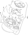
FIG. 3 is an exploded perspective view of the turbine housing assembly ofFIG. 2 ; -
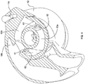
FIG. 4 is a sectioned perspective view of the turbine housing used in the assembly ofFIG. 2 ; -
FIG. 5 is an exploded perspective view of a bypass valve sub-assembly for the turbine housing assembly ofFIG. 2 ; -
FIG. 6A is an axial end view of the turbocharger ofFIG. 1 along line A-A, with the bypass valve in a fully closed position; -
FIG. 6B is a cross-sectional view along line B-B inFIG. 1 with the bypass valve in the fully closed position; -
FIG. 6C is a cross-sectional view along line C-C inFIG. 1 with the bypass valve in the fully closed position; -
FIG. 7A is an axial end view of the turbocharger ofFIG. 1 along line A-A, with the bypass valve in a first intermediate (partially open) position; -
FIG. 7B is a cross-sectional view along line B-B inFIG. 1 with the bypass valve in the first intermediate position; -
FIG. 7C is a cross-sectional view along line C-C inFIG. 1 with the bypass valve in the first intermediate position; -
FIG. 8A is an axial end view of the turbocharger ofFIG. 1 along line A-A, with the bypass valve in a second intermediate (further open) position; -
FIG. 8B is a cross-sectional view along line B-B inFIG. 1 with the bypass valve in the second intermediate position; -
FIG. 8C is a cross-sectional view along line C-C inFIG. 1 with the bypass valve in the second intermediate position; -
FIG. 9A is an axial end view of the turbocharger ofFIG. 1 along line A-A, with the bypass valve in a fully open position; -
FIG. 9B is a cross-sectional view along line B-B inFIG. 1 with the bypass valve in the fully open position; and -
FIG. 9C is a cross-sectional view along line C-C inFIG. 1 with the bypass valve in the fully open position. - The present disclosure now will be described more fully hereinafter with reference to the accompanying drawings in which some but not all embodiments of the inventions are shown. Indeed, these inventions may be embodied in many different forms and should not be construed as limited to the embodiments set forth herein; rather, these embodiments are provided so that this disclosure will satisfy applicable legal requirements. Like numbers refer to like elements throughout.
- A
turbocharger 20 in which embodiments of the present invention may be employed is shown inFIG. 1 . As shown, major sub-assemblies of theturbocharger 20 include acompressor assembly 30 and aturbine assembly 50. Thecompressor assembly 30 includes acompressor housing 32 and acompressor wheel 34 mounted therein and attached to one end of arotary shaft 36. A center housing assembly includes acenter housing 40 that is affixed to thecompressor housing 32 and that contains bearings for the rotary shaft. Theturbine assembly 50 includes aturbine housing 52 and aturbine wheel 54 mounted therein and attached to the opposite end of the rotary shaft. - The
turbine housing 52 defines a pair of separateexhaust gas inlets inlets 56a,b and distributes the gas around the chamber for feeding into theturbine wheel 54. In accordance with the invention, the sector-divided chamber has a pair of substantially 180-degree chamber sectors, also referred to herein as first andsecond scrolls second scrolls exhaust gas inlets inlet 56a andcylinders 2 and 4 can feed exhaust gas to theinlet 56b. Accordingly, when cylinder 1 is in the exhaust phase of its cycle and thus is feeding a pulse of exhaust gas toinlet 56a,cylinders 2 and 4 are not feeding exhaust gas toinlet 56b; then, whencylinder 2 is in its exhaust phase and thus is feeding a pulse of exhaust gas toinlet 56b, cylinders 1 and 3 are not feeding exhaust gas toinlet 56a; and so forth for all four cylinders. This alternating pulsing ofinlets scrolls - The
scrolls bypass volute 60 that includes a pair of substantially 180-degree bypass sectors turbine housing 52. Thefirst scroll 58a is connected only to thebypass sector 60a, and thesecond scroll 58b is connected only to thebypass sector 60b. Thebypass sectors 60a,b collectively surround anaxial bore 62 defined in the turbine housing, and are separated from each other by a pair of dividing walls 61 (best seen inFIG. 4 ) in the bypass volute, located diametrically opposite from each other. Exhaust gas that has passed through theturbine wheel 54 is exhausted from the turbine housing through thebore 62. Thebypass sectors 60a,b provide an alternative pathway for exhaust gas to flow without first having to pass through theturbine wheel 54. The gas can flow through thebypass sectors 60a,b, however, only if the bypass valve described below is open. - With reference particularly to
FIGS. 2 and3 , anannular bypass valve 70 is installed in a 360-degree annular portion of thebypass volute 60 that is just downstream of the twoseparate bypass sectors 60a,b. The bypass valve is operable for regulating flow through the bypass volute. The major components of theannular bypass valve 70 include astationary valve seat 72 and arotary valve rotor 74 in abutting engagement with the valve seat. Thevalve rotor 74 is constrained in the radial direction by the turbine housing but is free to rotate about its axis and to move axially against thevalve seat 72. Thevalve seat 72 is prevented from moving axially, radially, or rotationally. - The
valve seat 72 is a generally flat ring-shaped or annular member having a plurality oforifices 73 circumferentially spaced apart about a circumference of the valve seat, theorifices 73 extending generally axially between the upstream and downstream faces of the valve seat. Theorifices 73 in the illustrated embodiment are uniformly spaced about the circumference of the valve seat, but as further described below, non-uniform spacing of the orifices is also possible and can be advantageous in some circumstances. Thevalve seat 72 can be formed by any of various processes and materials. For example, processes that can be used include casting, casting and machining, and stamping. - The
rotary valve rotor 74 is a generally flat ring-shaped or annular member having a plurality oforifices 75 circumferentially spaced apart about a circumference of the valve seat, theorifices 75 extending generally axially between the upstream and downstream faces of the valve rotor. Theorifices 75 in the illustrated embodiment are uniformly spaced about the circumference of the valve rotor, and the number and spacing of theorifices 75 in the valve rotor are the same as the number and spacing of theorifices 73 in the valve seat. However, as further described below, non-uniform spacing of theorifices 75 is also possible and can be advantageous in some circumstances; furthermore, the spacings of theorifices - With reference to
FIG. 2 , rotation of thevalve rotor 74 is accomplished by arotary drive arm 110 connected to adrive shaft 100 that rotates about its central axis (also called a "drive axis" herein), which is parallel to the rotation axis of the turbocharger. Thedrive arm 110 is generally "L"-shaped, having a portion that extends generally perpendicular to the drive axis, and a distal end (i.e., the end remote from the end that is connected to the drive shaft 100) that defines a pin orrod portion 112 that extends generally parallel to the drive axis. Thevalve rotor 74 includes afork 79 that receives thepin portion 112 of thedrive arm 110. Thedrive shaft 100 can be connected to a rotary actuator's output shaft (not shown) to cause thedrive shaft 100 to rotate and therefore the distal end of thedrive arm 110 to sweep through an arc, thereby causing thevalve rotor 74 to rotate about its longitudinal axis. Thus, rotation of the actuator in one direction will rotate the valve rotor in a first direction (opposite to that of the actuator), and rotation of the actuator in the other direction will cause the valve rotor to rotate in a second direction. - With reference now to
FIGS. 4 and5 , the dividingwalls 61 that divide the portion of the bypass volute into the twobypass sectors hole 62 extending therethrough. Each of the dividingwalls 61 lies substantially in (or more precisely parallel to) a radial-axial plane. Thevalve rotor 74 includes a pair ofvalve members 76 each projecting from the face of the valve rotor that is on the opposite side thereof from thevalve seat 72. Thevalve members 76 project substantially in an axial direction from said face of the valve rotor and each lies substantially in (or more precisely parallel to) a radial-axial plane. Thevalve members 76 are located diametrically opposite from each other with respect to the central rotation axis of thevalve rotor 74 and are positioned such that in one rotational position of the valve rotor as shown inFIG. 6C , one of thevalve members 76 is abutting a face of one of the dividingwalls 61 so as to effectively close thehole 62 and prevent gas flow therethrough, and theother valve member 76 is abutting the other dividingwall 61 so as to effectively close thehole 62 and prevent gas flow therethrough. Accordingly, when the valve rotor is in this position (FIG. 6C ), the isolation of the two separate streams of exhaust gas is maintained through the twobypass sectors holes 62 in the dividing walls can be opened so as to interconnect the twobypass sectors valve rotor 74 away from theFIG. 6C position, such as shown inFIGS. 7C ,8C , and9C . A feature of the present invention is the timing of such opening of the dividing wall holes 62 with respect to the opening of thebypass valve 70. This is explained below. - With reference first to
FIGS. 6A-6C , the turbine housing and bypass valve assembly are shown with thevalve rotor 74 positioned in the closed position. AsFIG. 6B indicates, theorifices 73 in thestationary valve seat 72 are completely misaligned with theorifices 75 in the valve rotor, such that there is no overlap therebetween. Accordingly, exhaust gas is prevented from passing through thebypass valve 70. AsFIG. 6C shows, in this position, thevalve members 76 on the valve rotor are positioned so as to close the dividing wall holes 62. As a result, exhaust gas pulses can be fed alternately to the twoscrolls bypass valve 70 substantially prevents leakage from one of the scrolls to the other one because the possible pathways for such leakage through thebypass valve orifices valve seat 72 preferably includes twodams 72d as shown inFIG. 5 . Thedams 72d are raised ribs that project from the face of thevalve seat 72 toward and into contact with the opposing face of thevalve rotor 74. The dams are aligned with the dividingwalls 61 so that one 180-degree sector of the valve seat bounded between the dams is aligned with thefirst scroll 58a andbypass sector 60a and the other 180-degree sector is aligned with thesecond scroll 58b andbypass sector 60b. In addition to thedams 72d, the valve seat preferably includes raisedpads 73p that completely surround each of theorifices 73 and abut the face of the valve rotor so as to substantially prevent leakage of exhaust gas through the gap between the valve seat and valve rotor. - With reference to
FIGS. 7A-7C , thebypass valve 70 is shown in a second position in which thevalve rotor 74 is rotated sufficiently to open the dividing wall holes 62 so as to establish communication between the twobypass sectors FIG. 7B , thevalve rotor orifices 75 have still not begun to overlap with thevalve seat orifices 73. Accordingly, thebypass valve 70 remains closed to bypass flow. The communication between the bypass sectors, however, establishes a flow path between the twoscrolls inlet 56a into thefirst scroll 58a can flow into the associatedbypass sector 60a, through the dividing wall holes 62 into theother bypass sector 60b and from there into thesecond scroll 58b and then to the turbine wheel. Although this secondary pathway to the turbine wheel is circuitous and not as efficient as the direct path from thefirst scroll 58a to the wheel, it nevertheless establishes a secondary pathway that increases the total flow area to the turbine wheel. Likewise, a portion of an exhaust gas pulse into thesecond scroll 58b can find a secondary pathway to the wheel via thebypass sector 60b to theother bypass sector 60a and through to thefirst scroll 58a and then to the wheel. -
FIGS. 8A-8C illustrate a position of thevalve rotor 74 rotated still further relative to the position ofFIGS. 7A-C . In this further-rotated position, thevalve rotor orifices 75 have begun to overlap with thevalve seat orifices 73 but have not become fully aligned. Thus, in this partially open position of thebypass valve 70 some exhaust gas is able to flow through thebypass valve 70, bypassing the turbine wheel. -
FIGS. 9A-9C illustrate a fully open position of the bypass valve in which there is maximum overlap between thevalve rotor orifices 75 and thevalve seat orifices 73. - In accordance with the invention, when engine speed is low and exhaust gas energy is correspondingly low, the
bypass valve 70 can be placed in the fully closed position ofFIGS. 6A-C . In this position, the twoscrolls 58a,b are kept isolated from each other and thebypass sectors 60a,b are kept isolated from each other. Accordingly, the beneficial pulse effect on turbine stage efficiency for low speed operation is achieved because isolation of the two exhaust streams is maintained up to the turbine wheel. - On the other hand, when engine speed is higher, the isolation of the two scrolls is undesirable because the twin-scroll configuration penalizes turbine stage efficiency. In accordance with the invention, this penalty can be avoided or substantially mitigated by opening the bypass valve to the
FIG. 7A-C position so that the total flow area for each of the exhaust gas pulses is substantially increased via the alternative pathway opened up by establishing scroll-to-scroll communication through the dividing wall holes 62. The turbine thus behaves similar to a single-scroll turbine. - At still higher engine speeds when bypassing of the turbine is desired for maximum exhaust gas flow rate, the bypass valve can be opened to the partially open
FIG. 8A-C position or the fully openFIG. 9A-C position. - Many modifications and other embodiments of the inventions set forth herein will come to mind to one skilled in the art to which these inventions pertain having the benefit of the teachings presented in the foregoing descriptions and the associated drawings. For example, in the embodiment illustrated and described herein, the through-holes in the dividing walls become fully open before the bypass flow passages begin to open. Alternatively, however, other embodiments are included in the scope of the invention in which different scroll-to-scroll versus bypass opening schemes are employed. For instance, the bypass passages can begin to open before the scroll-to-scroll through-holes are fully opened. Therefore, it is to be understood that the inventions are not to be limited to the specific embodiments disclosed and that modifications and other embodiments are intended to be included within the scope of the appended claims. Although specific terms are employed herein, they are used in a generic and descriptive sense only and not for purposes of limitation.
Claims (4)
- A turbocharger comprising:a compressor wheel mounted within a compressor housing;a turbine housing defining a bore extending along a longitudinal axis and defining a sector-divided volute comprising first and second scrolls each occupying about 180 degrees of a full circumference about the longitudinal axis, the turbine housing further defining first and second exhaust gas inlets that are separate from each other and respectively feed exhaust gas into the first and second scrolls;a turbine wheel disposed in the turbine housing;the turbine housing defining an annular bypass passage surrounding the bore and arranged to allow exhaust gas in the chamber to bypass the turbine wheel, wherein a portion of the annular bypass passage adjacent the first and second scrolls is sector-divided by a pair of dividing walls located within the bypass passage and respectively disposed on diametrically opposite sides of the bore, the dividing walls dividing the portion of the bypass passage into half annular first and second bypass sectors, each dividing wall defining a through-hole establishing fluid communication between the bypass sectors, wherein the first scroll is connected to the first bypass sector to allow exhaust gas to pass from the first scroll to the first bypass sector, and the second scroll is connected to the second bypass sector to allow exhaust gas to pass from the second scroll to the second bypass sector;an annular bypass valve disposed in an annular portion of the bypass passage and operable when opened to allow exhaust gas to bypass the turbine wheel, the bypass valve comprising a fixed annular valve seat and an annular valve rotor that is disposed against the valve seat and is rotatable about the longitudinal axis, the valve seat defining a plurality of valve seat orifices extending axially therethrough and the valve rotor defining a plurality of valve rotor orifices extending axially therethrough, forming a plurality of orifice pairs each comprising a valve seat orifice and a corresponding valve rotor orifice, the orifices of the orifice pairs being arranged to overlap in some rotational positions of the valve rotor so as to create bypass flow passages formed by aligned portions of the valve seat orifices and valve rotor orifices,wherein the valve rotor includes a pair of valve members structured and arranged to respectively close the through-holes in the dividing walls in a fully closed rotational position of the valve rotor so as isolate the first and second bypass sectors from each other, the bypass flow passages also being closed in the fully closed position,wherein the valve rotor is structured such that in a first intermediate position displaced from the fully closed position the through-holes begin to open so as to permit exhaust gas to flow between the first and second bypass sectors while the bypass flow passages remain closed, and such that in a fully open position displaced further from the first intermediate position the through-holes are fully open and the bypass flow passages are fully open.
- The turbocharger of claim 1, wherein the valve rotor is rotatable to a second intermediate position, between the first intermediate position and the fully open position, and wherein the bypass flow passages are partially open in the second intermediate position.
- The turbocharger of claim 1, wherein the valve seat includes a pair of raised ribs projecting from the valve seat and abutting an opposing face of the valve rotor, the ribs being aligned with the dividing walls for preventing leakage of exhaust gas between the first and second scrolls via the bypass valve.
- The turbocharger of claim 3, wherein the valve seat includes a raised pad surrounding each valve seat orifice, the raised pads projecting from the valve seat and abutting the opposing face of the valve rotor for preventing leakage of exhaust gas between the first and second scrolls via the bypass valve.
Applications Claiming Priority (1)
| Application Number | Priority Date | Filing Date | Title |
|---|---|---|---|
| US15/046,265 US9932886B2 (en) | 2016-02-17 | 2016-02-17 | Turbocharger with rotary bypass valve operable to selectively configure the turbine volute as single-scroll or twin-scroll |
Publications (4)
| Publication Number | Publication Date |
|---|---|
| EP3232033A2 true EP3232033A2 (en) | 2017-10-18 |
| EP3232033A3 EP3232033A3 (en) | 2017-11-15 |
| EP3232033B1 EP3232033B1 (en) | 2018-08-08 |
| EP3232033B8 EP3232033B8 (en) | 2019-03-27 |
Family
ID=57389279
Family Applications (1)
| Application Number | Title | Priority Date | Filing Date |
|---|---|---|---|
| EP16199903.2A Not-in-force EP3232033B8 (en) | 2016-02-17 | 2016-11-21 | Turbocharger with rotary bypass valve operable to selectively configure the turbine volute as single-scroll or twin-scroll |
Country Status (3)
| Country | Link |
|---|---|
| US (1) | US9932886B2 (en) |
| EP (1) | EP3232033B8 (en) |
| CN (1) | CN107091146B (en) |
Families Citing this family (4)
| Publication number | Priority date | Publication date | Assignee | Title |
|---|---|---|---|---|
| GB201713461D0 (en) * | 2017-08-22 | 2017-10-04 | Cummins Ltd | Valve system |
| CN111663968B (en) * | 2019-03-08 | 2025-04-01 | 博格华纳公司 | Turbine housing, multi-channel turbine and multi-channel turbocharger |
| US11473494B1 (en) | 2021-04-01 | 2022-10-18 | Ford Global Technologies, Llc | Methods and systems for turbine bypass |
| US11572815B2 (en) | 2021-06-11 | 2023-02-07 | Ford Global Technologies, Llc | Methods and systems for turbine bypass |
Family Cites Families (10)
| Publication number | Priority date | Publication date | Assignee | Title |
|---|---|---|---|---|
| US3423926A (en) | 1966-08-31 | 1969-01-28 | Garrett Corp | Turbocharger control arrangement |
| DE19618160C2 (en) | 1996-05-07 | 1999-10-21 | Daimler Chrysler Ag | Exhaust gas turbocharger for an internal combustion engine |
| AU2003278524A1 (en) * | 2003-10-24 | 2005-05-11 | Honeywell International Inc | Sector-divided turbine assembly with axial piston variable-geometry mechanism |
| DE102004034070A1 (en) | 2004-07-15 | 2006-02-09 | Daimlerchrysler Ag | Internal combustion engine with an exhaust gas turbocharger |
| US8353664B2 (en) * | 2009-11-03 | 2013-01-15 | Honeywell International Inc. | Turbocharger with annular rotary bypass valve for the turbine |
| US8573929B2 (en) * | 2010-04-30 | 2013-11-05 | Honeywell International Inc. | Turbocharger with turbine nozzle vanes and an annular rotary bypass valve |
| JP5665486B2 (en) * | 2010-11-04 | 2015-02-04 | 三菱重工業株式会社 | Turbine housing of twin scroll turbocharger |
| US8534994B2 (en) * | 2010-12-13 | 2013-09-17 | Honeywell International Inc. | Turbocharger with divided turbine housing and annular rotary bypass valve for the turbine |
| US9593690B2 (en) * | 2013-06-26 | 2017-03-14 | Honeywell International Inc. | Turbocharger with an annular rotary bypass valve |
| US9422858B2 (en) | 2014-03-18 | 2016-08-23 | Honeywell International Inc. | Turbocharger with an annular rotary bypass valve |
-
2016
- 2016-02-17 US US15/046,265 patent/US9932886B2/en not_active Expired - Fee Related
- 2016-11-21 EP EP16199903.2A patent/EP3232033B8/en not_active Not-in-force
-
2017
- 2017-02-17 CN CN201710087185.8A patent/CN107091146B/en not_active Expired - Fee Related
Non-Patent Citations (1)
| Title |
|---|
| None |
Also Published As
| Publication number | Publication date |
|---|---|
| CN107091146B (en) | 2021-03-12 |
| US9932886B2 (en) | 2018-04-03 |
| CN107091146A (en) | 2017-08-25 |
| EP3232033B8 (en) | 2019-03-27 |
| EP3232033B1 (en) | 2018-08-08 |
| EP3232033A3 (en) | 2017-11-15 |
| US20170234212A1 (en) | 2017-08-17 |
Similar Documents
| Publication | Publication Date | Title |
|---|---|---|
| CN102061948B (en) | Turbine assembly for an exhaust gas-driven turbocharger having a variable nozzle | |
| CN102667098B (en) | Turbocharger with annular rotary bypass valve for turbine | |
| EP3441618B1 (en) | Turbocharger with a centrifugal compressor, having synergistic ported shroud and inlet-adjustment mechanism | |
| EP1352157B1 (en) | Variable geometry turbocharger with improved vane actuation | |
| EP2564044B1 (en) | Turbocharger with turbine nozzle vanes and an annular rotary bypass valve | |
| EP2463483B1 (en) | Turbocharger with divided turbine housing and annular rotary bypass valve for the turbine | |
| EP3232033B1 (en) | Turbocharger with rotary bypass valve operable to selectively configure the turbine volute as single-scroll or twin-scroll | |
| EP2655829A2 (en) | Turbocharger and engine cylinder head assembly | |
| EP1725742A1 (en) | Sector-divided turbine assembly with axial piston variable-geometry mechanism | |
| JP7196994B2 (en) | Variable displacement turbocharger | |
| JP5974501B2 (en) | Variable stationary blade mechanism of turbomachine | |
| JP4885949B2 (en) | Variable vane turbine | |
| KR20190113648A (en) | Turbine with adjusting ring | |
| JP7715841B2 (en) | Variable geometry turbine and turbocharger equipped with the same | |
| WO2021235027A1 (en) | Centrifugal compressor |
Legal Events
| Date | Code | Title | Description |
|---|---|---|---|
| PUAI | Public reference made under article 153(3) epc to a published international application that has entered the european phase |
Free format text: ORIGINAL CODE: 0009012 |
|
| STAA | Information on the status of an ep patent application or granted ep patent |
Free format text: STATUS: REQUEST FOR EXAMINATION WAS MADE |
|
| PUAL | Search report despatched |
Free format text: ORIGINAL CODE: 0009013 |
|
| 17P | Request for examination filed |
Effective date: 20161121 |
|
| AK | Designated contracting states |
Kind code of ref document: A2 Designated state(s): AL AT BE BG CH CY CZ DE DK EE ES FI FR GB GR HR HU IE IS IT LI LT LU LV MC MK MT NL NO PL PT RO RS SE SI SK SM TR |
|
| AX | Request for extension of the european patent |
Extension state: BA ME |
|
| AK | Designated contracting states |
Kind code of ref document: A3 Designated state(s): AL AT BE BG CH CY CZ DE DK EE ES FI FR GB GR HR HU IE IS IT LI LT LU LV MC MK MT NL NO PL PT RO RS SE SI SK SM TR |
|
| AX | Request for extension of the european patent |
Extension state: BA ME |
|
| RIC1 | Information provided on ipc code assigned before grant |
Ipc: F02B 37/18 20060101ALI20171010BHEP Ipc: F01D 25/24 20060101ALI20171010BHEP Ipc: F04D 29/28 20060101ALI20171010BHEP Ipc: F02B 37/22 20060101ALI20171010BHEP Ipc: F02B 37/02 20060101ALI20171010BHEP Ipc: F01D 5/02 20060101ALI20171010BHEP Ipc: F02C 6/12 20060101AFI20171010BHEP |
|
| GRAP | Despatch of communication of intention to grant a patent |
Free format text: ORIGINAL CODE: EPIDOSNIGR1 |
|
| STAA | Information on the status of an ep patent application or granted ep patent |
Free format text: STATUS: GRANT OF PATENT IS INTENDED |
|
| RIC1 | Information provided on ipc code assigned before grant |
Ipc: F01D 5/02 20060101ALI20180220BHEP Ipc: F02B 37/18 20060101ALI20180220BHEP Ipc: F01D 17/10 20060101ALI20180220BHEP Ipc: F02B 37/22 20060101ALI20180220BHEP Ipc: F02C 6/12 20060101AFI20180220BHEP Ipc: F01D 25/24 20060101ALI20180220BHEP Ipc: F04D 29/28 20060101ALI20180220BHEP Ipc: F02B 37/02 20060101ALI20180220BHEP |
|
| INTG | Intention to grant announced |
Effective date: 20180316 |
|
| GRAS | Grant fee paid |
Free format text: ORIGINAL CODE: EPIDOSNIGR3 |
|
| GRAA | (expected) grant |
Free format text: ORIGINAL CODE: 0009210 |
|
| STAA | Information on the status of an ep patent application or granted ep patent |
Free format text: STATUS: THE PATENT HAS BEEN GRANTED |
|
| AK | Designated contracting states |
Kind code of ref document: B1 Designated state(s): AL AT BE BG CH CY CZ DE DK EE ES FI FR GB GR HR HU IE IS IT LI LT LU LV MC MK MT NL NO PL PT RO RS SE SI SK SM TR |
|
| REG | Reference to a national code |
Ref country code: GB Ref legal event code: FG4D |
|
| REG | Reference to a national code |
Ref country code: CH Ref legal event code: EP Ref country code: AT Ref legal event code: REF Ref document number: 1027280 Country of ref document: AT Kind code of ref document: T Effective date: 20180815 |
|
| REG | Reference to a national code |
Ref country code: IE Ref legal event code: FG4D |
|
| REG | Reference to a national code |
Ref country code: DE Ref legal event code: R096 Ref document number: 602016004593 Country of ref document: DE |
|
| REG | Reference to a national code |
Ref country code: NL Ref legal event code: MP Effective date: 20180808 |
|
| REG | Reference to a national code |
Ref country code: LT Ref legal event code: MG4D |
|
| REG | Reference to a national code |
Ref country code: AT Ref legal event code: MK05 Ref document number: 1027280 Country of ref document: AT Kind code of ref document: T Effective date: 20180808 |
|
| PG25 | Lapsed in a contracting state [announced via postgrant information from national office to epo] |
Ref country code: NO Free format text: LAPSE BECAUSE OF FAILURE TO SUBMIT A TRANSLATION OF THE DESCRIPTION OR TO PAY THE FEE WITHIN THE PRESCRIBED TIME-LIMIT Effective date: 20181108 Ref country code: GR Free format text: LAPSE BECAUSE OF FAILURE TO SUBMIT A TRANSLATION OF THE DESCRIPTION OR TO PAY THE FEE WITHIN THE PRESCRIBED TIME-LIMIT Effective date: 20181109 Ref country code: RS Free format text: LAPSE BECAUSE OF FAILURE TO SUBMIT A TRANSLATION OF THE DESCRIPTION OR TO PAY THE FEE WITHIN THE PRESCRIBED TIME-LIMIT Effective date: 20180808 Ref country code: PL Free format text: LAPSE BECAUSE OF FAILURE TO SUBMIT A TRANSLATION OF THE DESCRIPTION OR TO PAY THE FEE WITHIN THE PRESCRIBED TIME-LIMIT Effective date: 20180808 Ref country code: SE Free format text: LAPSE BECAUSE OF FAILURE TO SUBMIT A TRANSLATION OF THE DESCRIPTION OR TO PAY THE FEE WITHIN THE PRESCRIBED TIME-LIMIT Effective date: 20180808 Ref country code: FI Free format text: LAPSE BECAUSE OF FAILURE TO SUBMIT A TRANSLATION OF THE DESCRIPTION OR TO PAY THE FEE WITHIN THE PRESCRIBED TIME-LIMIT Effective date: 20180808 Ref country code: LT Free format text: LAPSE BECAUSE OF FAILURE TO SUBMIT A TRANSLATION OF THE DESCRIPTION OR TO PAY THE FEE WITHIN THE PRESCRIBED TIME-LIMIT Effective date: 20180808 Ref country code: NL Free format text: LAPSE BECAUSE OF FAILURE TO SUBMIT A TRANSLATION OF THE DESCRIPTION OR TO PAY THE FEE WITHIN THE PRESCRIBED TIME-LIMIT Effective date: 20180808 Ref country code: IS Free format text: LAPSE BECAUSE OF FAILURE TO SUBMIT A TRANSLATION OF THE DESCRIPTION OR TO PAY THE FEE WITHIN THE PRESCRIBED TIME-LIMIT Effective date: 20181208 Ref country code: AT Free format text: LAPSE BECAUSE OF FAILURE TO SUBMIT A TRANSLATION OF THE DESCRIPTION OR TO PAY THE FEE WITHIN THE PRESCRIBED TIME-LIMIT Effective date: 20180808 Ref country code: BG Free format text: LAPSE BECAUSE OF FAILURE TO SUBMIT A TRANSLATION OF THE DESCRIPTION OR TO PAY THE FEE WITHIN THE PRESCRIBED TIME-LIMIT Effective date: 20181108 |
|
| RAP2 | Party data changed (patent owner data changed or rights of a patent transferred) |
Owner name: GARRETT TRANSPORTATION I INC. |
|
| PG25 | Lapsed in a contracting state [announced via postgrant information from national office to epo] |
Ref country code: LV Free format text: LAPSE BECAUSE OF FAILURE TO SUBMIT A TRANSLATION OF THE DESCRIPTION OR TO PAY THE FEE WITHIN THE PRESCRIBED TIME-LIMIT Effective date: 20180808 Ref country code: AL Free format text: LAPSE BECAUSE OF FAILURE TO SUBMIT A TRANSLATION OF THE DESCRIPTION OR TO PAY THE FEE WITHIN THE PRESCRIBED TIME-LIMIT Effective date: 20180808 Ref country code: HR Free format text: LAPSE BECAUSE OF FAILURE TO SUBMIT A TRANSLATION OF THE DESCRIPTION OR TO PAY THE FEE WITHIN THE PRESCRIBED TIME-LIMIT Effective date: 20180808 |
|
| REG | Reference to a national code |
Ref country code: CH Ref legal event code: PK Free format text: BERICHTIGUNG B8 |
|
| PG25 | Lapsed in a contracting state [announced via postgrant information from national office to epo] |
Ref country code: EE Free format text: LAPSE BECAUSE OF FAILURE TO SUBMIT A TRANSLATION OF THE DESCRIPTION OR TO PAY THE FEE WITHIN THE PRESCRIBED TIME-LIMIT Effective date: 20180808 Ref country code: IT Free format text: LAPSE BECAUSE OF FAILURE TO SUBMIT A TRANSLATION OF THE DESCRIPTION OR TO PAY THE FEE WITHIN THE PRESCRIBED TIME-LIMIT Effective date: 20180808 Ref country code: CZ Free format text: LAPSE BECAUSE OF FAILURE TO SUBMIT A TRANSLATION OF THE DESCRIPTION OR TO PAY THE FEE WITHIN THE PRESCRIBED TIME-LIMIT Effective date: 20180808 Ref country code: RO Free format text: LAPSE BECAUSE OF FAILURE TO SUBMIT A TRANSLATION OF THE DESCRIPTION OR TO PAY THE FEE WITHIN THE PRESCRIBED TIME-LIMIT Effective date: 20180808 Ref country code: ES Free format text: LAPSE BECAUSE OF FAILURE TO SUBMIT A TRANSLATION OF THE DESCRIPTION OR TO PAY THE FEE WITHIN THE PRESCRIBED TIME-LIMIT Effective date: 20180808 |
|
| REG | Reference to a national code |
Ref country code: DE Ref legal event code: R097 Ref document number: 602016004593 Country of ref document: DE |
|
| PG25 | Lapsed in a contracting state [announced via postgrant information from national office to epo] |
Ref country code: SK Free format text: LAPSE BECAUSE OF FAILURE TO SUBMIT A TRANSLATION OF THE DESCRIPTION OR TO PAY THE FEE WITHIN THE PRESCRIBED TIME-LIMIT Effective date: 20180808 Ref country code: DK Free format text: LAPSE BECAUSE OF FAILURE TO SUBMIT A TRANSLATION OF THE DESCRIPTION OR TO PAY THE FEE WITHIN THE PRESCRIBED TIME-LIMIT Effective date: 20180808 Ref country code: SM Free format text: LAPSE BECAUSE OF FAILURE TO SUBMIT A TRANSLATION OF THE DESCRIPTION OR TO PAY THE FEE WITHIN THE PRESCRIBED TIME-LIMIT Effective date: 20180808 |
|
| PLBE | No opposition filed within time limit |
Free format text: ORIGINAL CODE: 0009261 |
|
| STAA | Information on the status of an ep patent application or granted ep patent |
Free format text: STATUS: NO OPPOSITION FILED WITHIN TIME LIMIT |
|
| 26N | No opposition filed |
Effective date: 20190509 |
|
| PG25 | Lapsed in a contracting state [announced via postgrant information from national office to epo] |
Ref country code: LU Free format text: LAPSE BECAUSE OF NON-PAYMENT OF DUE FEES Effective date: 20181121 Ref country code: MC Free format text: LAPSE BECAUSE OF FAILURE TO SUBMIT A TRANSLATION OF THE DESCRIPTION OR TO PAY THE FEE WITHIN THE PRESCRIBED TIME-LIMIT Effective date: 20180808 |
|
| REG | Reference to a national code |
Ref country code: DE Ref legal event code: R081 Ref document number: 602016004593 Country of ref document: DE Owner name: GARRETT TRANSPORTATION I INC., TORRANCE, US Free format text: FORMER OWNER: HONEYWELL INTERNATIONAL INC., MORRIS PLAINS, N.J., US |
|
| REG | Reference to a national code |
Ref country code: BE Ref legal event code: MM Effective date: 20181130 |
|
| REG | Reference to a national code |
Ref country code: IE Ref legal event code: MM4A |
|
| PG25 | Lapsed in a contracting state [announced via postgrant information from national office to epo] |
Ref country code: SI Free format text: LAPSE BECAUSE OF FAILURE TO SUBMIT A TRANSLATION OF THE DESCRIPTION OR TO PAY THE FEE WITHIN THE PRESCRIBED TIME-LIMIT Effective date: 20180808 |
|
| PG25 | Lapsed in a contracting state [announced via postgrant information from national office to epo] |
Ref country code: IE Free format text: LAPSE BECAUSE OF NON-PAYMENT OF DUE FEES Effective date: 20181121 |
|
| PG25 | Lapsed in a contracting state [announced via postgrant information from national office to epo] |
Ref country code: BE Free format text: LAPSE BECAUSE OF NON-PAYMENT OF DUE FEES Effective date: 20181130 |
|
| PG25 | Lapsed in a contracting state [announced via postgrant information from national office to epo] |
Ref country code: MT Free format text: LAPSE BECAUSE OF NON-PAYMENT OF DUE FEES Effective date: 20181121 |
|
| PG25 | Lapsed in a contracting state [announced via postgrant information from national office to epo] |
Ref country code: TR Free format text: LAPSE BECAUSE OF FAILURE TO SUBMIT A TRANSLATION OF THE DESCRIPTION OR TO PAY THE FEE WITHIN THE PRESCRIBED TIME-LIMIT Effective date: 20180808 |
|
| PG25 | Lapsed in a contracting state [announced via postgrant information from national office to epo] |
Ref country code: PT Free format text: LAPSE BECAUSE OF FAILURE TO SUBMIT A TRANSLATION OF THE DESCRIPTION OR TO PAY THE FEE WITHIN THE PRESCRIBED TIME-LIMIT Effective date: 20180808 |
|
| PG25 | Lapsed in a contracting state [announced via postgrant information from national office to epo] |
Ref country code: CY Free format text: LAPSE BECAUSE OF FAILURE TO SUBMIT A TRANSLATION OF THE DESCRIPTION OR TO PAY THE FEE WITHIN THE PRESCRIBED TIME-LIMIT Effective date: 20180808 Ref country code: HU Free format text: LAPSE BECAUSE OF FAILURE TO SUBMIT A TRANSLATION OF THE DESCRIPTION OR TO PAY THE FEE WITHIN THE PRESCRIBED TIME-LIMIT; INVALID AB INITIO Effective date: 20161121 Ref country code: MK Free format text: LAPSE BECAUSE OF NON-PAYMENT OF DUE FEES Effective date: 20180808 |
|
| REG | Reference to a national code |
Ref country code: CH Ref legal event code: PL |
|
| PG25 | Lapsed in a contracting state [announced via postgrant information from national office to epo] |
Ref country code: LI Free format text: LAPSE BECAUSE OF NON-PAYMENT OF DUE FEES Effective date: 20191130 Ref country code: CH Free format text: LAPSE BECAUSE OF NON-PAYMENT OF DUE FEES Effective date: 20191130 |
|
| PGFP | Annual fee paid to national office [announced via postgrant information from national office to epo] |
Ref country code: DE Payment date: 20201130 Year of fee payment: 5 Ref country code: FR Payment date: 20201126 Year of fee payment: 5 Ref country code: GB Payment date: 20201126 Year of fee payment: 5 |
|
| REG | Reference to a national code |
Ref country code: DE Ref legal event code: R119 Ref document number: 602016004593 Country of ref document: DE |
|
| GBPC | Gb: european patent ceased through non-payment of renewal fee |
Effective date: 20211121 |
|
| PG25 | Lapsed in a contracting state [announced via postgrant information from national office to epo] |
Ref country code: GB Free format text: LAPSE BECAUSE OF NON-PAYMENT OF DUE FEES Effective date: 20211121 Ref country code: DE Free format text: LAPSE BECAUSE OF NON-PAYMENT OF DUE FEES Effective date: 20220601 |
|
| PG25 | Lapsed in a contracting state [announced via postgrant information from national office to epo] |
Ref country code: FR Free format text: LAPSE BECAUSE OF NON-PAYMENT OF DUE FEES Effective date: 20211130 |