EP3232032A1 - Cooling air architecture for compact size and performance improvement - Google Patents
Cooling air architecture for compact size and performance improvement Download PDFInfo
- Publication number
- EP3232032A1 EP3232032A1 EP17166056.6A EP17166056A EP3232032A1 EP 3232032 A1 EP3232032 A1 EP 3232032A1 EP 17166056 A EP17166056 A EP 17166056A EP 3232032 A1 EP3232032 A1 EP 3232032A1
- Authority
- EP
- European Patent Office
- Prior art keywords
- air
- gas turbine
- turbine engine
- set forth
- lower pressure
- Prior art date
- Legal status (The legal status is an assumption and is not a legal conclusion. Google has not performed a legal analysis and makes no representation as to the accuracy of the status listed.)
- Granted
Links
Images
Classifications
-
- F—MECHANICAL ENGINEERING; LIGHTING; HEATING; WEAPONS; BLASTING
- F02—COMBUSTION ENGINES; HOT-GAS OR COMBUSTION-PRODUCT ENGINE PLANTS
- F02C—GAS-TURBINE PLANTS; AIR INTAKES FOR JET-PROPULSION PLANTS; CONTROLLING FUEL SUPPLY IN AIR-BREATHING JET-PROPULSION PLANTS
- F02C7/00—Features, components parts, details or accessories, not provided for in, or of interest apart form groups F02C1/00 - F02C6/00; Air intakes for jet-propulsion plants
- F02C7/12—Cooling of plants
- F02C7/16—Cooling of plants characterised by cooling medium
- F02C7/18—Cooling of plants characterised by cooling medium the medium being gaseous, e.g. air
-
- F—MECHANICAL ENGINEERING; LIGHTING; HEATING; WEAPONS; BLASTING
- F01—MACHINES OR ENGINES IN GENERAL; ENGINE PLANTS IN GENERAL; STEAM ENGINES
- F01D—NON-POSITIVE DISPLACEMENT MACHINES OR ENGINES, e.g. STEAM TURBINES
- F01D25/00—Component parts, details, or accessories, not provided for in, or of interest apart from, other groups
- F01D25/08—Cooling; Heating; Heat-insulation
- F01D25/12—Cooling
-
- F—MECHANICAL ENGINEERING; LIGHTING; HEATING; WEAPONS; BLASTING
- F02—COMBUSTION ENGINES; HOT-GAS OR COMBUSTION-PRODUCT ENGINE PLANTS
- F02C—GAS-TURBINE PLANTS; AIR INTAKES FOR JET-PROPULSION PLANTS; CONTROLLING FUEL SUPPLY IN AIR-BREATHING JET-PROPULSION PLANTS
- F02C3/00—Gas-turbine plants characterised by the use of combustion products as the working fluid
- F02C3/04—Gas-turbine plants characterised by the use of combustion products as the working fluid having a turbine driving a compressor
-
- F—MECHANICAL ENGINEERING; LIGHTING; HEATING; WEAPONS; BLASTING
- F02—COMBUSTION ENGINES; HOT-GAS OR COMBUSTION-PRODUCT ENGINE PLANTS
- F02C—GAS-TURBINE PLANTS; AIR INTAKES FOR JET-PROPULSION PLANTS; CONTROLLING FUEL SUPPLY IN AIR-BREATHING JET-PROPULSION PLANTS
- F02C3/00—Gas-turbine plants characterised by the use of combustion products as the working fluid
- F02C3/04—Gas-turbine plants characterised by the use of combustion products as the working fluid having a turbine driving a compressor
- F02C3/13—Gas-turbine plants characterised by the use of combustion products as the working fluid having a turbine driving a compressor having variable working fluid interconnections between turbines or compressors or stages of different rotors
-
- F—MECHANICAL ENGINEERING; LIGHTING; HEATING; WEAPONS; BLASTING
- F02—COMBUSTION ENGINES; HOT-GAS OR COMBUSTION-PRODUCT ENGINE PLANTS
- F02C—GAS-TURBINE PLANTS; AIR INTAKES FOR JET-PROPULSION PLANTS; CONTROLLING FUEL SUPPLY IN AIR-BREATHING JET-PROPULSION PLANTS
- F02C6/00—Plural gas-turbine plants; Combinations of gas-turbine plants with other apparatus; Adaptations of gas-turbine plants for special use
- F02C6/04—Gas-turbine plants providing heated or pressurised working fluid for other apparatus, e.g. without mechanical power output
- F02C6/06—Gas-turbine plants providing heated or pressurised working fluid for other apparatus, e.g. without mechanical power output providing compressed gas
- F02C6/08—Gas-turbine plants providing heated or pressurised working fluid for other apparatus, e.g. without mechanical power output providing compressed gas the gas being bled from the gas-turbine compressor
-
- F—MECHANICAL ENGINEERING; LIGHTING; HEATING; WEAPONS; BLASTING
- F02—COMBUSTION ENGINES; HOT-GAS OR COMBUSTION-PRODUCT ENGINE PLANTS
- F02C—GAS-TURBINE PLANTS; AIR INTAKES FOR JET-PROPULSION PLANTS; CONTROLLING FUEL SUPPLY IN AIR-BREATHING JET-PROPULSION PLANTS
- F02C7/00—Features, components parts, details or accessories, not provided for in, or of interest apart form groups F02C1/00 - F02C6/00; Air intakes for jet-propulsion plants
- F02C7/12—Cooling of plants
- F02C7/14—Cooling of plants of fluids in the plant, e.g. lubricant or fuel
- F02C7/141—Cooling of plants of fluids in the plant, e.g. lubricant or fuel of working fluid
- F02C7/143—Cooling of plants of fluids in the plant, e.g. lubricant or fuel of working fluid before or between the compressor stages
-
- F—MECHANICAL ENGINEERING; LIGHTING; HEATING; WEAPONS; BLASTING
- F02—COMBUSTION ENGINES; HOT-GAS OR COMBUSTION-PRODUCT ENGINE PLANTS
- F02C—GAS-TURBINE PLANTS; AIR INTAKES FOR JET-PROPULSION PLANTS; CONTROLLING FUEL SUPPLY IN AIR-BREATHING JET-PROPULSION PLANTS
- F02C7/00—Features, components parts, details or accessories, not provided for in, or of interest apart form groups F02C1/00 - F02C6/00; Air intakes for jet-propulsion plants
- F02C7/12—Cooling of plants
- F02C7/16—Cooling of plants characterised by cooling medium
- F02C7/18—Cooling of plants characterised by cooling medium the medium being gaseous, e.g. air
- F02C7/185—Cooling means for reducing the temperature of the cooling air or gas
-
- F—MECHANICAL ENGINEERING; LIGHTING; HEATING; WEAPONS; BLASTING
- F04—POSITIVE - DISPLACEMENT MACHINES FOR LIQUIDS; PUMPS FOR LIQUIDS OR ELASTIC FLUIDS
- F04D—NON-POSITIVE-DISPLACEMENT PUMPS
- F04D29/00—Details, component parts, or accessories
- F04D29/58—Cooling; Heating; Diminishing heat transfer
- F04D29/582—Cooling; Heating; Diminishing heat transfer specially adapted for elastic fluid pumps
- F04D29/5826—Cooling at least part of the working fluid in a heat exchanger
-
- F—MECHANICAL ENGINEERING; LIGHTING; HEATING; WEAPONS; BLASTING
- F04—POSITIVE - DISPLACEMENT MACHINES FOR LIQUIDS; PUMPS FOR LIQUIDS OR ELASTIC FLUIDS
- F04D—NON-POSITIVE-DISPLACEMENT PUMPS
- F04D29/00—Details, component parts, or accessories
- F04D29/58—Cooling; Heating; Diminishing heat transfer
- F04D29/582—Cooling; Heating; Diminishing heat transfer specially adapted for elastic fluid pumps
- F04D29/5826—Cooling at least part of the working fluid in a heat exchanger
- F04D29/5833—Cooling at least part of the working fluid in a heat exchanger flow schemes and regulation thereto
-
- F—MECHANICAL ENGINEERING; LIGHTING; HEATING; WEAPONS; BLASTING
- F05—INDEXING SCHEMES RELATING TO ENGINES OR PUMPS IN VARIOUS SUBCLASSES OF CLASSES F01-F04
- F05D—INDEXING SCHEME FOR ASPECTS RELATING TO NON-POSITIVE-DISPLACEMENT MACHINES OR ENGINES, GAS-TURBINES OR JET-PROPULSION PLANTS
- F05D2220/00—Application
- F05D2220/30—Application in turbines
- F05D2220/36—Application in turbines specially adapted for the fan of turbofan engines
-
- F—MECHANICAL ENGINEERING; LIGHTING; HEATING; WEAPONS; BLASTING
- F05—INDEXING SCHEMES RELATING TO ENGINES OR PUMPS IN VARIOUS SUBCLASSES OF CLASSES F01-F04
- F05D—INDEXING SCHEME FOR ASPECTS RELATING TO NON-POSITIVE-DISPLACEMENT MACHINES OR ENGINES, GAS-TURBINES OR JET-PROPULSION PLANTS
- F05D2260/00—Function
- F05D2260/20—Heat transfer, e.g. cooling
-
- F—MECHANICAL ENGINEERING; LIGHTING; HEATING; WEAPONS; BLASTING
- F05—INDEXING SCHEMES RELATING TO ENGINES OR PUMPS IN VARIOUS SUBCLASSES OF CLASSES F01-F04
- F05D—INDEXING SCHEME FOR ASPECTS RELATING TO NON-POSITIVE-DISPLACEMENT MACHINES OR ENGINES, GAS-TURBINES OR JET-PROPULSION PLANTS
- F05D2260/00—Function
- F05D2260/20—Heat transfer, e.g. cooling
- F05D2260/211—Heat transfer, e.g. cooling by intercooling, e.g. during a compression cycle
-
- F—MECHANICAL ENGINEERING; LIGHTING; HEATING; WEAPONS; BLASTING
- F05—INDEXING SCHEMES RELATING TO ENGINES OR PUMPS IN VARIOUS SUBCLASSES OF CLASSES F01-F04
- F05D—INDEXING SCHEME FOR ASPECTS RELATING TO NON-POSITIVE-DISPLACEMENT MACHINES OR ENGINES, GAS-TURBINES OR JET-PROPULSION PLANTS
- F05D2260/00—Function
- F05D2260/20—Heat transfer, e.g. cooling
- F05D2260/213—Heat transfer, e.g. cooling by the provision of a heat exchanger within the cooling circuit
-
- F—MECHANICAL ENGINEERING; LIGHTING; HEATING; WEAPONS; BLASTING
- F05—INDEXING SCHEMES RELATING TO ENGINES OR PUMPS IN VARIOUS SUBCLASSES OF CLASSES F01-F04
- F05D—INDEXING SCHEME FOR ASPECTS RELATING TO NON-POSITIVE-DISPLACEMENT MACHINES OR ENGINES, GAS-TURBINES OR JET-PROPULSION PLANTS
- F05D2260/00—Function
- F05D2260/60—Fluid transfer
- F05D2260/606—Bypassing the fluid
-
- F—MECHANICAL ENGINEERING; LIGHTING; HEATING; WEAPONS; BLASTING
- F05—INDEXING SCHEMES RELATING TO ENGINES OR PUMPS IN VARIOUS SUBCLASSES OF CLASSES F01-F04
- F05D—INDEXING SCHEME FOR ASPECTS RELATING TO NON-POSITIVE-DISPLACEMENT MACHINES OR ENGINES, GAS-TURBINES OR JET-PROPULSION PLANTS
- F05D2270/00—Control
- F05D2270/30—Control parameters, e.g. input parameters
- F05D2270/306—Mass flow
- F05D2270/3062—Mass flow of the auxiliary fluid for heating or cooling purposes
-
- Y—GENERAL TAGGING OF NEW TECHNOLOGICAL DEVELOPMENTS; GENERAL TAGGING OF CROSS-SECTIONAL TECHNOLOGIES SPANNING OVER SEVERAL SECTIONS OF THE IPC; TECHNICAL SUBJECTS COVERED BY FORMER USPC CROSS-REFERENCE ART COLLECTIONS [XRACs] AND DIGESTS
- Y02—TECHNOLOGIES OR APPLICATIONS FOR MITIGATION OR ADAPTATION AGAINST CLIMATE CHANGE
- Y02T—CLIMATE CHANGE MITIGATION TECHNOLOGIES RELATED TO TRANSPORTATION
- Y02T50/00—Aeronautics or air transport
- Y02T50/60—Efficient propulsion technologies, e.g. for aircraft
Definitions
- This application relates to a heat exchanger which cools air to be utilized for various uses on a gas turbine engine, and which is relatively compact.
- Gas turbine engines typically include a fan delivering air into a compressor section. The air is compressed and passed into a combustor where it is mixed with fuel and ignited. Products of this combustion pass downstream over turbine rotors driving them to rotate.
- the fan also delivers air into a bypass duct which does not travel to the compressor, but instead provides propulsion as it exits the engine.
- a cold coldest source of air on a gas turbine engine is this fan bypass air.
- the fan rotated at the same speed as a compressor rotor.
- a gear reduction has been placed between the two such that the fan rotates at slower speeds.
- the diameter of the fan can increase, and a bypass ratio, or amount of air delivered into the bypass duct compared to the volume of air delivered into the compressor section also increases.
- the air has been cooled by bypass air.
- the fan driven air in the bypass duct is at relatively low pressure and may not always adequately cool the air to be utilized as cooling air.
- a gas turbine engine has a fan and a compressor section with a first lower pressure location and a second higher pressure location.
- a heat exchanger and a higher pressure tap from the second higher pressure location pass through the heat exchanger. Air in the higher pressure tap is cooled by air from a lower pressure tap from the first lower pressure location.
- a valve controls flow to the heat exchanger from the lower pressure tap, the valve being controlled to limit flow from the lower pressure tap under certain conditions.
- the valve is moved to limit the flow of air from the lower pressure tap when the engine is operating at lower power conditions.
- the valve is moved to limit the flow of air from the lower pressure tap at idle.
- the valve also limits the flow of air from the lower pressure tap at cruise conditions.
- valve is moved to limit flow from the lower pressure tap at ground idle conditions to allow the air from the higher pressure tap to preheat the heat exchanger prior to a takeoff condition.
- the valve is controlled to allow the flow of air from the lower pressure tap during higher pressure conditions.
- the higher pressure conditions include takeoff conditions.
- the air from the higher pressure tap is delivered to uses in a turbine section downstream of the heat exchanger.
- valve is positioned downstream of the heat exchanger.
- the fan delivers air into a bypass duct defined between an outer periphery of a core engine housing and an inner periphery of a nacelle and the heat exchanger is positioned in the bypass duct.
- an exhaust of the air from the lower pressure tap is delivered into the bypass duct.
- the fan delivers air into a bypass duct defined between an outer periphery of a core engine housing and an inner periphery of a nacelle and the heat exchanger is positioned in the bypass duct.
- a nacelle is positioned outwardly of a core engine housing and the heat exchanger is positioned within the core engine housing.
- an exhaust of the heat exchanger is at a downstream end of the core engine housing.
- a downstream end of the nacelle is upstream of the downstream end of the core engine housing.
- the exhaust is through a pylon which is provided to mount the engine to an aircraft.
- a nacelle and a core housing have pivoting structures and a seal, and an exhaust of the lower pressure tap is through the seal into the bypass duct.
- the second higher pressure location is at a downstream end of a high pressure compressor section.
- the first lower pressure location is within a low pressure compressor section.
- the first lower pressure location is within a low pressure compressor section.
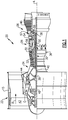
- FIG. 1 schematically illustrates a gas turbine engine 20.
- the gas turbine engine 20 is disclosed herein as a two-spool turbofan that generally incorporates a fan section 22, a compressor section 24, a combustor section 26 and a turbine section 28.
- Alternative engines might include an augmentor section (not shown) among other systems or features.
- the fan section 22 drives air along a bypass flow path B in a bypass duct defined within a nacelle 15, while the compressor section 24 drives air along a core flow path C for compression and communication into the combustor section 26 then expansion through the turbine section 28.
- the exemplary engine 20 generally includes a low speed spool 30 and a high speed spool 32 mounted for rotation about an engine central longitudinal axis A relative to an engine static structure 36 via several bearing systems 38. It should be understood that various bearing systems 38 at various locations may alternatively or additionally be provided, and the location of bearing systems 38 may be varied as appropriate to the application.
- the low speed spool 30 generally includes an inner shaft 40 that interconnects a fan 42, a first (or low) pressure compressor 44 and a first (or low) pressure turbine 46.
- the inner shaft 40 is connected to the fan 42 through a speed change mechanism, which in exemplary gas turbine engine 20 is illustrated as a geared architecture 48 to drive the fan 42 at a lower speed than the low speed spool 30.
- the high speed spool 32 includes an outer shaft 50 that interconnects a second (or high) pressure compressor 52 and a second (or high) pressure turbine 54.
- a combustor 56 is arranged in exemplary gas turbine 20 between the high pressure compressor 52 and the high pressure turbine 54.
- a mid-turbine frame 57 of the engine static structure 36 is arranged generally between the high pressure turbine 54 and the low pressure turbine 46.
- the mid-turbine frame 57 further supports bearing systems 38 in the turbine section 28.
- the inner shaft 40 and the outer shaft 50 are concentric and rotate via bearing systems 38 about the engine central longitudinal axis A which is collinear with their longitudinal axes.
- the core airflow is compressed by the low pressure compressor 44 then the high pressure compressor 52, mixed and burned with fuel in the combustor 56, then expanded over the high pressure turbine 54 and low pressure turbine 46.
- the mid-turbine frame 57 includes airfoils 59 which are in the core airflow path C.
- the turbines 46, 54 rotationally drive the respective low speed spool 30 and high speed spool 32 in response to the expansion.
- gear system 48 may be located aft of combustor section 26 or even aft of turbine section 28, and fan section 22 may be positioned forward or aft of the location of gear system 48.
- the engine 20 in one example is a high-bypass geared aircraft engine.
- the engine 20 bypass ratio is greater than about six (6), with an example embodiment being greater than about ten (10)
- the geared architecture 48 is an epicyclic gear train, such as a planetary gear system or other gear system, with a gear reduction ratio of greater than about 2.3
- the low pressure turbine 46 has a pressure ratio that is greater than about five.
- the engine 20 bypass ratio is greater than about ten (10:1)
- the fan diameter is significantly larger than that of the low pressure compressor 44
- the low pressure turbine 46 has a pressure ratio that is greater than about five 5:1.
- Low pressure turbine 46 pressure ratio is pressure measured prior to inlet of low pressure turbine 46 as related to the pressure at the outlet of the low pressure turbine 46 prior to an exhaust nozzle.
- the geared architecture 48 may be an epicycle gear train, such as a planetary gear system or other gear system, with a gear reduction ratio of greater than about 2.3:1. It should be understood, however, that the above parameters are only exemplary of one embodiment of a geared architecture engine and that the present invention is applicable to other gas turbine engines including direct drive turbofans.
- the fan section 22 of the engine 20 is designed for a particular flight condition -- typically cruise at about 0.8 Mach and about 35,000 feet (10,668 meters).
- the flight condition of 0.8 Mach and 35,000 ft (10,668 meters), with the engine at its best fuel consumption - also known as "bucket cruise Thrust Specific Fuel Consumption ('TSFC')" - is the industry standard parameter of lbm of fuel being burned divided by lbf of thrust the engine produces at that minimum point.
- "Low fan pressure ratio” is the pressure ratio across the fan blade alone, without a Fan Exit Guide Vane (“FEGV”) system.
- the low fan pressure ratio as disclosed herein according to one non-limiting embodiment is less than about 1.45.
- the "Low corrected fan tip speed” as disclosed herein according to one non-limiting embodiment is less than about 1150 ft / second (350.5 meters/second).
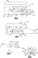
- Figure 2 shows an engine 100 including a fan rotor 102 positioned within a nacelle 104.
- a core housing 106 encloses a low pressure compressor section 108 and a high pressure compressor section 110.
- a combustor 112 is downstream of the high pressure compressor 110.
- a high pressure turbine 114 drives the high pressure compressor 110 and a fan drive turbine 116 drives the low pressure compressor 108.
- An intermediate gear reduction 118 allows the fan rotor 102 to rotate with the low pressure compressor section 108, but at lower speeds.
- the fan rotor 102 delivers bypass air into a bypass duct B.
- a lower pressure cooling air tap 120 is tapped from a location in the low pressure compressor section 108.
- the tap 120 could come from upstream portions of the high pressure compressor section 110.
- a higher pressure tap 122 is taken from downstream locations in the high pressure compressor 110, and passes through a heat exchanger 124.
- the air taken from the tap 120 is also passed over the heat exchanger 124, with the two flows from each tap 120 and 122 maintained separate in heat exchanger 124.
- the air from tap 120 cools the relatively hot air from the tap 122. Downstream of the heat exchanger 124, the air from tap 122 passes to a line 126 and is utilized for various uses on a gas turbine engine such as cooling components in the high pressure turbine section 114.
- the air from tap 120 is exhausted at 128 and a valve 130 is placed upstream of the exhaust 128.
- the heat exchanger 124 is mounted in the bypass duct B in this embodiment, and the exhaust 128 also passes into the bypass duct.
- the exhaust 128 will contribute to the propulsion provided by the air from the fan rotor 102 passing through the bypass duct B.
- bypass air alone could cool the air from tap 122.
- valve 130 is controlled by control 131 to block the flow of air from the tap 120 under low power conditions. This increases the efficiency of the engine as the air compressed to tap 120 may be combusted rather than used for cooling.
- the valve 130 may be open such that air passes from tap 120 through the heat exchanger 124 and cools the air from the tap 122.
- the control 131 for the valve may modulate or even close the valve 130 under lower power conditions such as cruise or idle.
- the flow of hot air from the tap 122 may be utilized to preheat the heat exchanger 124 at ground idle.
- the valve 130 will be modulated towards a closed position, if not closed altogether. In this manner, the air from tap 122 will preheat the heat exchanger 124. Now, when the engine moves to takeoff conditions, the air 122 will become much hotter. Without the preheating of the heat exchanger 124, there would be thermal stresses on the heat exchanger components. However, since the air 122 did pass through the heat exchanger 124 at the lower power idle condition, but without the flow of cooling air from tap 120, the thermal stresses on the heat exchanger 124 will be reduced.
- FIG 3 shows an engine embodiment 133.
- nacelle 132 is positioned outside of a fan rotor 134.
- a core engine housing 136 houses the heat exchanger 138.
- a valve 146 is also provided with a control 147 which may operate in a manner similar to that disclosed above with regard to Figure 2 .
- the exhaust 148 passes outwardly of a nozzle at the end 152 of the core housing 136.
- the exhaust air 148 need not overcome the pressure in the bypass duct B.
- the end 152 is downstream of the end 150 of the nacelle 132, such that the pressure seen by exhaust 148 will be relatively low compared to that seen by the exhaust 128 in the Figure 2 embodiment.
- Figure 4 shows an engine embodiment 160 having a nacelle 162, a core housing 164, and an exhaust cone 166 that can be combined with any prior embodiment.
- a pylon 168 mounts the engine 160 to an aircraft.
- the exhaust 170 is positioned in the pylon 168.
- the exhaust will thus "see” lower pressure than if the exhaust were in the bypass duct.
- Figure 5 shows an engine embodiment 180 that can be combined with any prior embodiment.
- the nacelle and the core housings are typically formed of two pivoting sections 182 and 184 that pivot about point P to process access to internal components.
- the core housing has sections 186 and 188 that pivot with the sections 184 and 182, respectively.
- a so-called "kiss seal" 190 is positioned within the housing portion 188 and receives the exhaust 192 in this embodiment.
- the heat exchanger 193 would be mounted within the core housing, similar to the Figure 3 embodiment. However, the air would exhaust into the bypass stream and the bypass duct B, and provide propulsion air.
- the controls 131 and 147 may be stand-alone controls, or may be incorporated into a control for the overall engine such as a FADEC.
- valves 130 and 146 are shown schematically, any known way of limiting airflow may be utilized, such as a door or other controllable valve.
Landscapes
- Engineering & Computer Science (AREA)
- Chemical & Material Sciences (AREA)
- Combustion & Propulsion (AREA)
- Mechanical Engineering (AREA)
- General Engineering & Computer Science (AREA)
- Physics & Mathematics (AREA)
- Thermal Sciences (AREA)
- Control Of Turbines (AREA)
Abstract
Description
- This application relates to a heat exchanger which cools air to be utilized for various uses on a gas turbine engine, and which is relatively compact.
- Gas turbine engines are known and typically include a fan delivering air into a compressor section. The air is compressed and passed into a combustor where it is mixed with fuel and ignited. Products of this combustion pass downstream over turbine rotors driving them to rotate.
- The fan also delivers air into a bypass duct which does not travel to the compressor, but instead provides propulsion as it exits the engine. A cold coldest source of air on a gas turbine engine is this fan bypass air.
- Historically, the fan rotated at the same speed as a compressor rotor. However, more recently, a gear reduction has been placed between the two such that the fan rotates at slower speeds. With this, the diameter of the fan can increase, and a bypass ratio, or amount of air delivered into the bypass duct compared to the volume of air delivered into the compressor section also increases.
- As can be appreciated, there are challenges with design and operation of a gas turbine engine. In particular, the turbine section is exposed to very hot temperatures. Thus, high pressure cooling air is typically delivered for various cooling uses, especially in the turbine section. The highest pressure source on the engine would be associated with a downstream location in a high pressure compressor section. However, this air is hot.
- Thus, it is known to cool the high pressure air to be used for cooling. Typically, the air has been cooled by bypass air. However, and especially with the use of geared turbofans, the fan driven air in the bypass duct is at relatively low pressure and may not always adequately cool the air to be utilized as cooling air.
- In a featured embodiment, a gas turbine engine has a fan and a compressor section with a first lower pressure location and a second higher pressure location. A heat exchanger and a higher pressure tap from the second higher pressure location pass through the heat exchanger. Air in the higher pressure tap is cooled by air from a lower pressure tap from the first lower pressure location. A valve controls flow to the heat exchanger from the lower pressure tap, the valve being controlled to limit flow from the lower pressure tap under certain conditions.
- In another embodiment according to the previous embodiment, the valve is moved to limit the flow of air from the lower pressure tap when the engine is operating at lower power conditions.
- In another embodiment according to any of the previous embodiments, the valve is moved to limit the flow of air from the lower pressure tap at idle.
- In another embodiment according to any of the previous embodiments, the valve also limits the flow of air from the lower pressure tap at cruise conditions.
- In another embodiment according to any of the previous embodiments, the valve is moved to limit flow from the lower pressure tap at ground idle conditions to allow the air from the higher pressure tap to preheat the heat exchanger prior to a takeoff condition.
- In another embodiment according to any of the previous embodiments, the valve is controlled to allow the flow of air from the lower pressure tap during higher pressure conditions.
- In another embodiment according to any of the previous embodiments, the higher pressure conditions include takeoff conditions.
- In another embodiment according to any of the previous embodiments, the air from the higher pressure tap is delivered to uses in a turbine section downstream of the heat exchanger.
- In another embodiment according to any of the previous embodiments, the valve is positioned downstream of the heat exchanger.
- In another embodiment according to any of the previous embodiments, the fan delivers air into a bypass duct defined between an outer periphery of a core engine housing and an inner periphery of a nacelle and the heat exchanger is positioned in the bypass duct.
- In another embodiment according to any of the previous embodiments, an exhaust of the air from the lower pressure tap is delivered into the bypass duct.
- In another embodiment according to any of the previous embodiments, the fan delivers air into a bypass duct defined between an outer periphery of a core engine housing and an inner periphery of a nacelle and the heat exchanger is positioned in the bypass duct.
- In another embodiment according to any of the previous embodiments, a nacelle is positioned outwardly of a core engine housing and the heat exchanger is positioned within the core engine housing.
- In another embodiment according to any of the previous embodiments, an exhaust of the heat exchanger is at a downstream end of the core engine housing.
- In another embodiment according to any of the previous embodiments, a downstream end of the nacelle is upstream of the downstream end of the core engine housing.
- In another embodiment according to any of the previous embodiments, the exhaust is through a pylon which is provided to mount the engine to an aircraft.
- In another embodiment according to any of the previous embodiments, a nacelle and a core housing have pivoting structures and a seal, and an exhaust of the lower pressure tap is through the seal into the bypass duct.
- In another embodiment according to any of the previous embodiments, the second higher pressure location is at a downstream end of a high pressure compressor section.
- In another embodiment according to any of the previous embodiments, the first lower pressure location is within a low pressure compressor section.
- In another embodiment according to any of the previous embodiments, the first lower pressure location is within a low pressure compressor section.
- These and other features may be best understood from the following drawings and specification.
-
-
Figure 1 schematically shows an embodiment of a gas turbine engine. -
Figure 2 shows features of an embodiment. -
Figure 3 shows an alternative embodiment. -
Figure 4 shows another alternative embodiment. -
Figure 5 shows yet another alternative embodiment. -
Figure 1 schematically illustrates agas turbine engine 20. Thegas turbine engine 20 is disclosed herein as a two-spool turbofan that generally incorporates afan section 22, acompressor section 24, a combustor section 26 and aturbine section 28. Alternative engines might include an augmentor section (not shown) among other systems or features. Thefan section 22 drives air along a bypass flow path B in a bypass duct defined within anacelle 15, while thecompressor section 24 drives air along a core flow path C for compression and communication into the combustor section 26 then expansion through theturbine section 28. Although depicted as a two-spool turbofan gas turbine engine in the disclosed non-limiting embodiment, it should be understood that the concepts described herein are not limited to use with two-spool turbofans as the teachings may be applied to other types of turbine engines including three-spool architectures. - The
exemplary engine 20 generally includes alow speed spool 30 and ahigh speed spool 32 mounted for rotation about an engine central longitudinal axis A relative to an enginestatic structure 36 viaseveral bearing systems 38. It should be understood thatvarious bearing systems 38 at various locations may alternatively or additionally be provided, and the location ofbearing systems 38 may be varied as appropriate to the application. - The
low speed spool 30 generally includes aninner shaft 40 that interconnects afan 42, a first (or low)pressure compressor 44 and a first (or low)pressure turbine 46. Theinner shaft 40 is connected to thefan 42 through a speed change mechanism, which in exemplarygas turbine engine 20 is illustrated as a gearedarchitecture 48 to drive thefan 42 at a lower speed than thelow speed spool 30. Thehigh speed spool 32 includes anouter shaft 50 that interconnects a second (or high)pressure compressor 52 and a second (or high)pressure turbine 54. Acombustor 56 is arranged inexemplary gas turbine 20 between thehigh pressure compressor 52 and thehigh pressure turbine 54. Amid-turbine frame 57 of the enginestatic structure 36 is arranged generally between thehigh pressure turbine 54 and thelow pressure turbine 46. Themid-turbine frame 57 further supports bearingsystems 38 in theturbine section 28. Theinner shaft 40 and theouter shaft 50 are concentric and rotate viabearing systems 38 about the engine central longitudinal axis A which is collinear with their longitudinal axes. - The core airflow is compressed by the
low pressure compressor 44 then thehigh pressure compressor 52, mixed and burned with fuel in thecombustor 56, then expanded over thehigh pressure turbine 54 andlow pressure turbine 46. Themid-turbine frame 57 includesairfoils 59 which are in the core airflow path C. Theturbines low speed spool 30 andhigh speed spool 32 in response to the expansion. It will be appreciated that each of the positions of thefan section 22,compressor section 24, combustor section 26,turbine section 28, and fandrive gear system 48 may be varied. For example,gear system 48 may be located aft of combustor section 26 or even aft ofturbine section 28, andfan section 22 may be positioned forward or aft of the location ofgear system 48. - The
engine 20 in one example is a high-bypass geared aircraft engine. In a further example, theengine 20 bypass ratio is greater than about six (6), with an example embodiment being greater than about ten (10), the gearedarchitecture 48 is an epicyclic gear train, such as a planetary gear system or other gear system, with a gear reduction ratio of greater than about 2.3 and thelow pressure turbine 46 has a pressure ratio that is greater than about five. In one disclosed embodiment, theengine 20 bypass ratio is greater than about ten (10:1), the fan diameter is significantly larger than that of thelow pressure compressor 44, and thelow pressure turbine 46 has a pressure ratio that is greater than about five 5:1.Low pressure turbine 46 pressure ratio is pressure measured prior to inlet oflow pressure turbine 46 as related to the pressure at the outlet of thelow pressure turbine 46 prior to an exhaust nozzle. The gearedarchitecture 48 may be an epicycle gear train, such as a planetary gear system or other gear system, with a gear reduction ratio of greater than about 2.3:1. It should be understood, however, that the above parameters are only exemplary of one embodiment of a geared architecture engine and that the present invention is applicable to other gas turbine engines including direct drive turbofans. - A significant amount of thrust is provided by the bypass flow B due to the high bypass ratio. The
fan section 22 of theengine 20 is designed for a particular flight condition -- typically cruise at about 0.8 Mach and about 35,000 feet (10,668 meters). The flight condition of 0.8 Mach and 35,000 ft (10,668 meters), with the engine at its best fuel consumption - also known as "bucket cruise Thrust Specific Fuel Consumption ('TSFC')" - is the industry standard parameter of lbm of fuel being burned divided by lbf of thrust the engine produces at that minimum point. "Low fan pressure ratio" is the pressure ratio across the fan blade alone, without a Fan Exit Guide Vane ("FEGV") system. The low fan pressure ratio as disclosed herein according to one non-limiting embodiment is less than about 1.45. "Low corrected fan tip speed" is the actual fan tip speed in ft/sec divided by an industry standard temperature correction of [(Tram °R) / (518.7 °R)]0.5 (where °R = K x 9/5). The "Low corrected fan tip speed" as disclosed herein according to one non-limiting embodiment is less than about 1150 ft / second (350.5 meters/second). -
Figure 2 shows anengine 100 including afan rotor 102 positioned within anacelle 104. Acore housing 106 encloses a lowpressure compressor section 108 and a highpressure compressor section 110. Acombustor 112 is downstream of thehigh pressure compressor 110. Ahigh pressure turbine 114 drives thehigh pressure compressor 110 and afan drive turbine 116 drives thelow pressure compressor 108. Anintermediate gear reduction 118 allows thefan rotor 102 to rotate with the lowpressure compressor section 108, but at lower speeds. - As shown, the
fan rotor 102 delivers bypass air into a bypass duct B. A lower pressure coolingair tap 120 is tapped from a location in the lowpressure compressor section 108. Alternatively, thetap 120 could come from upstream portions of the highpressure compressor section 110. Ahigher pressure tap 122 is taken from downstream locations in thehigh pressure compressor 110, and passes through aheat exchanger 124. The air taken from thetap 120 is also passed over theheat exchanger 124, with the two flows from eachtap heat exchanger 124. The air fromtap 120 cools the relatively hot air from thetap 122. Downstream of theheat exchanger 124, the air fromtap 122 passes to aline 126 and is utilized for various uses on a gas turbine engine such as cooling components in the highpressure turbine section 114. - The air from
tap 120 is exhausted at 128 and avalve 130 is placed upstream of theexhaust 128. Theheat exchanger 124 is mounted in the bypass duct B in this embodiment, and theexhaust 128 also passes into the bypass duct. Thus, theexhaust 128 will contribute to the propulsion provided by the air from thefan rotor 102 passing through the bypass duct B. Under certain conditions, it may not be necessary to have the air fromtap 120 cooling the air fromtap 122. As an example, at cruise conditions, perhaps bypass air alone could cool the air fromtap 122. - Thus, the
valve 130 is controlled bycontrol 131 to block the flow of air from thetap 120 under low power conditions. This increases the efficiency of the engine as the air compressed to tap 120 may be combusted rather than used for cooling. - As an example, at takeoff, the
valve 130 may be open such that air passes fromtap 120 through theheat exchanger 124 and cools the air from thetap 122. However, thecontrol 131 for the valve may modulate or even close thevalve 130 under lower power conditions such as cruise or idle. - In addition, the flow of hot air from the
tap 122 may be utilized to preheat theheat exchanger 124 at ground idle. Thevalve 130 will be modulated towards a closed position, if not closed altogether. In this manner, the air fromtap 122 will preheat theheat exchanger 124. Now, when the engine moves to takeoff conditions, theair 122 will become much hotter. Without the preheating of theheat exchanger 124, there would be thermal stresses on the heat exchanger components. However, since theair 122 did pass through theheat exchanger 124 at the lower power idle condition, but without the flow of cooling air fromtap 120, the thermal stresses on theheat exchanger 124 will be reduced. -
Figure 3 shows anengine embodiment 133. Again,nacelle 132 is positioned outside of afan rotor 134. Acore engine housing 136 houses theheat exchanger 138. Again, there is a tap 140 for cooling air from a lower pressure location in the compressor and thetap 142 from a higher pressure location. Air fromtap 142, downstream of theheat exchanger 138, passes to point 144 where it moves towards the turbine section for various cooling purposes. Avalve 146 is also provided with acontrol 147 which may operate in a manner similar to that disclosed above with regard toFigure 2 . - In this embodiment, the
exhaust 148 passes outwardly of a nozzle at theend 152 of thecore housing 136. In this manner, theexhaust air 148 need not overcome the pressure in the bypass duct B. Notably, theend 152 is downstream of theend 150 of thenacelle 132, such that the pressure seen byexhaust 148 will be relatively low compared to that seen by theexhaust 128 in theFigure 2 embodiment. -
Figure 4 shows anengine embodiment 160 having anacelle 162, acore housing 164, and anexhaust cone 166 that can be combined with any prior embodiment. Apylon 168 mounts theengine 160 to an aircraft. Theexhaust 170 is positioned in thepylon 168. Here again, the exhaust will thus "see" lower pressure than if the exhaust were in the bypass duct. -
Figure 5 shows anengine embodiment 180 that can be combined with any prior embodiment. As known, the nacelle and the core housings are typically formed of two pivotingsections sections sections housing portion 188 and receives theexhaust 192 in this embodiment. In this embodiment, theheat exchanger 193 would be mounted within the core housing, similar to theFigure 3 embodiment. However, the air would exhaust into the bypass stream and the bypass duct B, and provide propulsion air. - The
controls - While the
valves - Although an embodiment of this invention has been disclosed, a worker of ordinary skill in this art would recognize that certain modifications would come within the scope of this invention. For that reason, the following claims should be studied to determine the true scope and content of this invention.
Claims (15)
- A gas turbine engine (20;100;133;160;180) comprising:a fan (42;102;134) and a compressor section (24) having a first lower pressure location and a second higher pressure location; anda heat exchanger (124;138;193) and a higher pressure tap (122;142) from said second higher pressure location passing through said heat exchanger (124;138;143), and air in said higher pressure tap (122;142) being cooled by air from a lower pressure tap (120;140) from said first lower pressure location, and a valve (130;146) controlling flow to said heat exchanger (124;138;193) from said lower pressure tap (120;140), said valve (130;146) being controlled to limit flow from said lower pressure tap (120;140) under certain conditions.
- The gas turbine engine as set forth in claim 1, wherein said valve (130;146) is moved to limit the flow of air from said lower pressure tap (120;140) when the engine is operating at lower power conditions.
- The gas turbine engine as set forth in claim 1 or 2, wherein said valve (130;146) is moved to limit the flow of air from said lower pressure tap (120;140) at idle.
- The gas turbine engine as set forth in any preceding claim, wherein said valve (130;146) (also) limits the flow of air from said lower pressure tap (120;140) at cruise conditions.
- The gas turbine engine as set forth in any preceding claim, wherein said valve (130;146) is moved to limit flow from said lower pressure tap (120;140) at ground idle conditions to allow said air from said higher pressure tap (122;142) to preheat said heat exchanger (124;138;193) prior to a takeoff condition.
- The gas turbine engine as set forth in any preceding claim, wherein said valve (130;146) is controlled to allow the flow of air from said lower pressure tap (120;140) during higher pressure conditions, wherein, optionally, said higher pressure conditions include takeoff conditions.
- The gas turbine engine as set forth in any preceding claim, wherein said air from said higher pressure tap (122;142) is delivered to uses in a turbine section (28) downstream of said heat exchanger (124;138;193).
- The gas turbine engine as set forth in any preceding claim, wherein said fan (42;102) delivers air into a bypass duct (B) defined between an outer periphery of a core engine housing (106;164) and an inner periphery of a nacelle (15;104;162) and said heat exchanger (124;193) is positioned in said bypass duct (B).
- The gas turbine engine as set forth in claim 8, wherein an exhaust (128;192) of said air from said lower pressure tap (120) is delivered into said bypass duct (B).
- The gas turbine engine as set forth in any of claims 1 to 7, wherein a nacelle (15;132;162) is positioned outwardly of a core engine housing (136;164) and said heat exchanger (138;193) is positioned within said core engine housing (136;164).
- The gas turbine engine as set forth in claim 10, wherein an exhaust (148) of said heat exchanger (138;193) is at a downstream end (152) of said core engine housing (136;164).
- The gas turbine engine as set forth in claim 10, wherein an exhaust (170) from said lower pressure tap (120) is through a pylon (168) which is provided to mount said engine (160) to an aircraft.
- The gas turbine engine as set forth in any of claims 1 to 8, wherein a or said nacelle and a or said core housing (164) have pivoting structures (182;184;186;188) and a seal (190), and an exhaust (192) of said lower pressure tap (120) is through said seal (190) into a or said bypass duct (B).
- The gas turbine engine as set forth in any preceding claim, wherein said second higher pressure location is at a downstream end of a high pressure compressor section (52;100).
- The gas turbine engine as set forth in any preceding claim, wherein said first lower pressure location is within a low pressure compressor section (44;108).
Applications Claiming Priority (1)
| Application Number | Priority Date | Filing Date | Title |
|---|---|---|---|
| US15/097,782 US10760492B2 (en) | 2016-04-13 | 2016-04-13 | Cooling air architecture for compact size and performance improvement |
Publications (2)
| Publication Number | Publication Date |
|---|---|
| EP3232032A1 true EP3232032A1 (en) | 2017-10-18 |
| EP3232032B1 EP3232032B1 (en) | 2022-12-07 |
Family
ID=58548562
Family Applications (1)
| Application Number | Title | Priority Date | Filing Date |
|---|---|---|---|
| EP17166056.6A Active EP3232032B1 (en) | 2016-04-13 | 2017-04-11 | Cooling air architecture for compact size and performance improvement |
Country Status (2)
| Country | Link |
|---|---|
| US (1) | US10760492B2 (en) |
| EP (1) | EP3232032B1 (en) |
Cited By (2)
| Publication number | Priority date | Publication date | Assignee | Title |
|---|---|---|---|---|
| EP3296548A3 (en) * | 2016-08-23 | 2018-06-13 | United Technologies Corporation | Heat exchanger for gas turbine engine mounted in intermediate case |
| EP3539873A1 (en) * | 2018-03-13 | 2019-09-18 | Airbus Operations S.A.S. | Propulsion system of an aircraft comprising a dual-flow jet engine and a compact air sampling system |
Families Citing this family (1)
| Publication number | Priority date | Publication date | Assignee | Title |
|---|---|---|---|---|
| US10436115B2 (en) * | 2016-08-22 | 2019-10-08 | United Technologies Corporation | Heat exchanger for gas turbine engine with support damper mounting |
Citations (3)
| Publication number | Priority date | Publication date | Assignee | Title |
|---|---|---|---|---|
| EP0608142A1 (en) * | 1993-01-21 | 1994-07-27 | General Electric Company | Gas turbine engine cooling system |
| EP2604825A2 (en) * | 2011-12-14 | 2013-06-19 | Rolls-Royce plc | Controller for cooling the turbine section of a gas turbine engine |
| EP2960468A1 (en) * | 2014-06-27 | 2015-12-30 | Frederick M. Schwarz | Geared turbofan engine with low pressure environmental control system for aircraft |
Family Cites Families (7)
| Publication number | Priority date | Publication date | Assignee | Title |
|---|---|---|---|---|
| US4503683A (en) | 1983-12-16 | 1985-03-12 | The Garrett Corporation | Compact cooling turbine-heat exchanger assembly |
| EP1257349B1 (en) | 2000-02-23 | 2008-08-13 | Schlom, Leslie | A heat exchanger for cooling and for a pre-cooler for turbine intake air conditioning |
| US8181443B2 (en) | 2008-12-10 | 2012-05-22 | Pratt & Whitney Canada Corp. | Heat exchanger to cool turbine air cooling flow |
| US9062604B2 (en) * | 2011-01-14 | 2015-06-23 | Hamilton Sundstrand Corporation | Low pressure bleed architecture |
| US9222411B2 (en) * | 2011-12-21 | 2015-12-29 | General Electric Company | Bleed air and hot section component cooling air system and method |
| US9234707B2 (en) * | 2012-09-21 | 2016-01-12 | The Boeing Company | Heat exchanger systems and methods for controlling airflow cooling |
| US10221862B2 (en) * | 2015-04-24 | 2019-03-05 | United Technologies Corporation | Intercooled cooling air tapped from plural locations |
-
2016
- 2016-04-13 US US15/097,782 patent/US10760492B2/en active Active
-
2017
- 2017-04-11 EP EP17166056.6A patent/EP3232032B1/en active Active
Patent Citations (3)
| Publication number | Priority date | Publication date | Assignee | Title |
|---|---|---|---|---|
| EP0608142A1 (en) * | 1993-01-21 | 1994-07-27 | General Electric Company | Gas turbine engine cooling system |
| EP2604825A2 (en) * | 2011-12-14 | 2013-06-19 | Rolls-Royce plc | Controller for cooling the turbine section of a gas turbine engine |
| EP2960468A1 (en) * | 2014-06-27 | 2015-12-30 | Frederick M. Schwarz | Geared turbofan engine with low pressure environmental control system for aircraft |
Cited By (4)
| Publication number | Priority date | Publication date | Assignee | Title |
|---|---|---|---|---|
| EP3296548A3 (en) * | 2016-08-23 | 2018-06-13 | United Technologies Corporation | Heat exchanger for gas turbine engine mounted in intermediate case |
| US10982595B2 (en) | 2016-08-23 | 2021-04-20 | Raytheon Technologies Corporation | Heat exchanger for gas turbine engine mounted in intermediate case |
| EP3539873A1 (en) * | 2018-03-13 | 2019-09-18 | Airbus Operations S.A.S. | Propulsion system of an aircraft comprising a dual-flow jet engine and a compact air sampling system |
| FR3078947A1 (en) * | 2018-03-13 | 2019-09-20 | Airbus Operations | AIRCRAFT PROPULSION SYSTEM COMPRISING A DOUBLE FLOW TURBOREACTOR AND A REDUCED SIZE AIR SAMPLING SYSTEM |
Also Published As
| Publication number | Publication date |
|---|---|
| US10760492B2 (en) | 2020-09-01 |
| EP3232032B1 (en) | 2022-12-07 |
| US20170298825A1 (en) | 2017-10-19 |
Similar Documents
| Publication | Publication Date | Title |
|---|---|---|
| US11236675B2 (en) | Gas turbine engine with intercooled cooling air and turbine drive | |
| EP3181868B1 (en) | Control cooling air by heat exchanger bypass | |
| US11149643B2 (en) | Heat exchanger mounted at rear of gas turbine engine for challenging temperature applications | |
| EP3239493A1 (en) | Simple heat exchanger using super alloy materials | |
| EP3792473B1 (en) | Fuel cooled cooling air | |
| EP3330515B1 (en) | Gas turbine engine | |
| EP3232032B1 (en) | Cooling air architecture for compact size and performance improvement | |
| US11293354B2 (en) | Integrated cooling air boost compressor and fuel pump | |
| EP3199779B1 (en) | Cooling air for variable geometry turbine | |
| EP3296548B1 (en) | Heat exchanger for gas turbine engine mounted in intermediate case | |
| US11021981B2 (en) | Downstream turbine vane cooling for a gas turbine engine | |
| EP3388637B1 (en) | Cooling air chamber for blade outer air seal | |
| EP3388625A1 (en) | Cooled cooling air to blade outer air seal through a static vane | |
| EP3358152B1 (en) | External mixing chamber for a gas turbine engine with cooled turbine cooling air | |
| EP3181869B1 (en) | Compressor core inner diameter cooling | |
| EP3348812B1 (en) | Cooled gas turbine engine cooling air with cold air dump |
Legal Events
| Date | Code | Title | Description |
|---|---|---|---|
| PUAI | Public reference made under article 153(3) epc to a published international application that has entered the european phase |
Free format text: ORIGINAL CODE: 0009012 |
|
| STAA | Information on the status of an ep patent application or granted ep patent |
Free format text: STATUS: THE APPLICATION HAS BEEN PUBLISHED |
|
| AK | Designated contracting states |
Kind code of ref document: A1 Designated state(s): AL AT BE BG CH CY CZ DE DK EE ES FI FR GB GR HR HU IE IS IT LI LT LU LV MC MK MT NL NO PL PT RO RS SE SI SK SM TR |
|
| AX | Request for extension of the european patent |
Extension state: BA ME |
|
| STAA | Information on the status of an ep patent application or granted ep patent |
Free format text: STATUS: REQUEST FOR EXAMINATION WAS MADE |
|
| 17P | Request for examination filed |
Effective date: 20180417 |
|
| RBV | Designated contracting states (corrected) |
Designated state(s): AL AT BE BG CH CY CZ DE DK EE ES FI FR GB GR HR HU IE IS IT LI LT LU LV MC MK MT NL NO PL PT RO RS SE SI SK SM TR |
|
| STAA | Information on the status of an ep patent application or granted ep patent |
Free format text: STATUS: EXAMINATION IS IN PROGRESS |
|
| 17Q | First examination report despatched |
Effective date: 20201201 |
|
| RAP1 | Party data changed (applicant data changed or rights of an application transferred) |
Owner name: RAYTHEON TECHNOLOGIES CORPORATION |
|
| GRAP | Despatch of communication of intention to grant a patent |
Free format text: ORIGINAL CODE: EPIDOSNIGR1 |
|
| STAA | Information on the status of an ep patent application or granted ep patent |
Free format text: STATUS: GRANT OF PATENT IS INTENDED |
|
| INTG | Intention to grant announced |
Effective date: 20220818 |
|
| GRAS | Grant fee paid |
Free format text: ORIGINAL CODE: EPIDOSNIGR3 |
|
| GRAA | (expected) grant |
Free format text: ORIGINAL CODE: 0009210 |
|
| STAA | Information on the status of an ep patent application or granted ep patent |
Free format text: STATUS: THE PATENT HAS BEEN GRANTED |
|
| AK | Designated contracting states |
Kind code of ref document: B1 Designated state(s): AL AT BE BG CH CY CZ DE DK EE ES FI FR GB GR HR HU IE IS IT LI LT LU LV MC MK MT NL NO PL PT RO RS SE SI SK SM TR |
|
| REG | Reference to a national code |
Ref country code: GB Ref legal event code: FG4D |
|
| REG | Reference to a national code |
Ref country code: CH Ref legal event code: EP Ref country code: AT Ref legal event code: REF Ref document number: 1536440 Country of ref document: AT Kind code of ref document: T Effective date: 20221215 |
|
| REG | Reference to a national code |
Ref country code: DE Ref legal event code: R096 Ref document number: 602017064314 Country of ref document: DE |
|
| REG | Reference to a national code |
Ref country code: IE Ref legal event code: FG4D |
|
| REG | Reference to a national code |
Ref country code: LT Ref legal event code: MG9D |
|
| REG | Reference to a national code |
Ref country code: NL Ref legal event code: MP Effective date: 20221207 |
|
| PG25 | Lapsed in a contracting state [announced via postgrant information from national office to epo] |
Ref country code: SE Free format text: LAPSE BECAUSE OF FAILURE TO SUBMIT A TRANSLATION OF THE DESCRIPTION OR TO PAY THE FEE WITHIN THE PRESCRIBED TIME-LIMIT Effective date: 20221207 Ref country code: NO Free format text: LAPSE BECAUSE OF FAILURE TO SUBMIT A TRANSLATION OF THE DESCRIPTION OR TO PAY THE FEE WITHIN THE PRESCRIBED TIME-LIMIT Effective date: 20230307 Ref country code: LT Free format text: LAPSE BECAUSE OF FAILURE TO SUBMIT A TRANSLATION OF THE DESCRIPTION OR TO PAY THE FEE WITHIN THE PRESCRIBED TIME-LIMIT Effective date: 20221207 Ref country code: FI Free format text: LAPSE BECAUSE OF FAILURE TO SUBMIT A TRANSLATION OF THE DESCRIPTION OR TO PAY THE FEE WITHIN THE PRESCRIBED TIME-LIMIT Effective date: 20221207 Ref country code: ES Free format text: LAPSE BECAUSE OF FAILURE TO SUBMIT A TRANSLATION OF THE DESCRIPTION OR TO PAY THE FEE WITHIN THE PRESCRIBED TIME-LIMIT Effective date: 20221207 |
|
| REG | Reference to a national code |
Ref country code: AT Ref legal event code: MK05 Ref document number: 1536440 Country of ref document: AT Kind code of ref document: T Effective date: 20221207 |
|
| PG25 | Lapsed in a contracting state [announced via postgrant information from national office to epo] |
Ref country code: RS Free format text: LAPSE BECAUSE OF FAILURE TO SUBMIT A TRANSLATION OF THE DESCRIPTION OR TO PAY THE FEE WITHIN THE PRESCRIBED TIME-LIMIT Effective date: 20221207 Ref country code: PL Free format text: LAPSE BECAUSE OF FAILURE TO SUBMIT A TRANSLATION OF THE DESCRIPTION OR TO PAY THE FEE WITHIN THE PRESCRIBED TIME-LIMIT Effective date: 20221207 Ref country code: LV Free format text: LAPSE BECAUSE OF FAILURE TO SUBMIT A TRANSLATION OF THE DESCRIPTION OR TO PAY THE FEE WITHIN THE PRESCRIBED TIME-LIMIT Effective date: 20221207 Ref country code: HR Free format text: LAPSE BECAUSE OF FAILURE TO SUBMIT A TRANSLATION OF THE DESCRIPTION OR TO PAY THE FEE WITHIN THE PRESCRIBED TIME-LIMIT Effective date: 20221207 Ref country code: GR Free format text: LAPSE BECAUSE OF FAILURE TO SUBMIT A TRANSLATION OF THE DESCRIPTION OR TO PAY THE FEE WITHIN THE PRESCRIBED TIME-LIMIT Effective date: 20230308 |
|
| P01 | Opt-out of the competence of the unified patent court (upc) registered |
Effective date: 20230520 |
|
| PG25 | Lapsed in a contracting state [announced via postgrant information from national office to epo] |
Ref country code: NL Free format text: LAPSE BECAUSE OF FAILURE TO SUBMIT A TRANSLATION OF THE DESCRIPTION OR TO PAY THE FEE WITHIN THE PRESCRIBED TIME-LIMIT Effective date: 20221207 |
|
| PG25 | Lapsed in a contracting state [announced via postgrant information from national office to epo] |
Ref country code: SM Free format text: LAPSE BECAUSE OF FAILURE TO SUBMIT A TRANSLATION OF THE DESCRIPTION OR TO PAY THE FEE WITHIN THE PRESCRIBED TIME-LIMIT Effective date: 20221207 Ref country code: RO Free format text: LAPSE BECAUSE OF FAILURE TO SUBMIT A TRANSLATION OF THE DESCRIPTION OR TO PAY THE FEE WITHIN THE PRESCRIBED TIME-LIMIT Effective date: 20221207 Ref country code: PT Free format text: LAPSE BECAUSE OF FAILURE TO SUBMIT A TRANSLATION OF THE DESCRIPTION OR TO PAY THE FEE WITHIN THE PRESCRIBED TIME-LIMIT Effective date: 20230410 Ref country code: EE Free format text: LAPSE BECAUSE OF FAILURE TO SUBMIT A TRANSLATION OF THE DESCRIPTION OR TO PAY THE FEE WITHIN THE PRESCRIBED TIME-LIMIT Effective date: 20221207 Ref country code: CZ Free format text: LAPSE BECAUSE OF FAILURE TO SUBMIT A TRANSLATION OF THE DESCRIPTION OR TO PAY THE FEE WITHIN THE PRESCRIBED TIME-LIMIT Effective date: 20221207 Ref country code: AT Free format text: LAPSE BECAUSE OF FAILURE TO SUBMIT A TRANSLATION OF THE DESCRIPTION OR TO PAY THE FEE WITHIN THE PRESCRIBED TIME-LIMIT Effective date: 20221207 |
|
| PG25 | Lapsed in a contracting state [announced via postgrant information from national office to epo] |
Ref country code: SK Free format text: LAPSE BECAUSE OF FAILURE TO SUBMIT A TRANSLATION OF THE DESCRIPTION OR TO PAY THE FEE WITHIN THE PRESCRIBED TIME-LIMIT Effective date: 20221207 Ref country code: IS Free format text: LAPSE BECAUSE OF FAILURE TO SUBMIT A TRANSLATION OF THE DESCRIPTION OR TO PAY THE FEE WITHIN THE PRESCRIBED TIME-LIMIT Effective date: 20230407 Ref country code: AL Free format text: LAPSE BECAUSE OF FAILURE TO SUBMIT A TRANSLATION OF THE DESCRIPTION OR TO PAY THE FEE WITHIN THE PRESCRIBED TIME-LIMIT Effective date: 20221207 |
|
| REG | Reference to a national code |
Ref country code: DE Ref legal event code: R097 Ref document number: 602017064314 Country of ref document: DE |
|
| PLBE | No opposition filed within time limit |
Free format text: ORIGINAL CODE: 0009261 |
|
| STAA | Information on the status of an ep patent application or granted ep patent |
Free format text: STATUS: NO OPPOSITION FILED WITHIN TIME LIMIT |
|
| PG25 | Lapsed in a contracting state [announced via postgrant information from national office to epo] |
Ref country code: DK Free format text: LAPSE BECAUSE OF FAILURE TO SUBMIT A TRANSLATION OF THE DESCRIPTION OR TO PAY THE FEE WITHIN THE PRESCRIBED TIME-LIMIT Effective date: 20221207 |
|
| RAP4 | Party data changed (patent owner data changed or rights of a patent transferred) |
Owner name: RTX CORPORATION |
|
| 26N | No opposition filed |
Effective date: 20230908 |
|
| PG25 | Lapsed in a contracting state [announced via postgrant information from national office to epo] |
Ref country code: SI Free format text: LAPSE BECAUSE OF FAILURE TO SUBMIT A TRANSLATION OF THE DESCRIPTION OR TO PAY THE FEE WITHIN THE PRESCRIBED TIME-LIMIT Effective date: 20221207 |
|
| REG | Reference to a national code |
Ref country code: CH Ref legal event code: PL |
|
| PG25 | Lapsed in a contracting state [announced via postgrant information from national office to epo] |
Ref country code: LU Free format text: LAPSE BECAUSE OF NON-PAYMENT OF DUE FEES Effective date: 20230411 |
|
| REG | Reference to a national code |
Ref country code: BE Ref legal event code: MM Effective date: 20230430 |
|
| PG25 | Lapsed in a contracting state [announced via postgrant information from national office to epo] |
Ref country code: MC Free format text: LAPSE BECAUSE OF FAILURE TO SUBMIT A TRANSLATION OF THE DESCRIPTION OR TO PAY THE FEE WITHIN THE PRESCRIBED TIME-LIMIT Effective date: 20221207 |
|
| PG25 | Lapsed in a contracting state [announced via postgrant information from national office to epo] |
Ref country code: MC Free format text: LAPSE BECAUSE OF FAILURE TO SUBMIT A TRANSLATION OF THE DESCRIPTION OR TO PAY THE FEE WITHIN THE PRESCRIBED TIME-LIMIT Effective date: 20221207 Ref country code: LI Free format text: LAPSE BECAUSE OF NON-PAYMENT OF DUE FEES Effective date: 20230430 Ref country code: CH Free format text: LAPSE BECAUSE OF NON-PAYMENT OF DUE FEES Effective date: 20230430 |
|
| REG | Reference to a national code |
Ref country code: IE Ref legal event code: MM4A |
|
| PG25 | Lapsed in a contracting state [announced via postgrant information from national office to epo] |
Ref country code: BE Free format text: LAPSE BECAUSE OF NON-PAYMENT OF DUE FEES Effective date: 20230430 |
|
| PG25 | Lapsed in a contracting state [announced via postgrant information from national office to epo] |
Ref country code: IE Free format text: LAPSE BECAUSE OF NON-PAYMENT OF DUE FEES Effective date: 20230411 |
|
| PG25 | Lapsed in a contracting state [announced via postgrant information from national office to epo] |
Ref country code: IE Free format text: LAPSE BECAUSE OF NON-PAYMENT OF DUE FEES Effective date: 20230411 |
|
| PG25 | Lapsed in a contracting state [announced via postgrant information from national office to epo] |
Ref country code: IT Free format text: LAPSE BECAUSE OF FAILURE TO SUBMIT A TRANSLATION OF THE DESCRIPTION OR TO PAY THE FEE WITHIN THE PRESCRIBED TIME-LIMIT Effective date: 20221207 |
|
| PG25 | Lapsed in a contracting state [announced via postgrant information from national office to epo] |
Ref country code: BG Free format text: LAPSE BECAUSE OF FAILURE TO SUBMIT A TRANSLATION OF THE DESCRIPTION OR TO PAY THE FEE WITHIN THE PRESCRIBED TIME-LIMIT Effective date: 20221207 |
|
| PG25 | Lapsed in a contracting state [announced via postgrant information from national office to epo] |
Ref country code: BG Free format text: LAPSE BECAUSE OF FAILURE TO SUBMIT A TRANSLATION OF THE DESCRIPTION OR TO PAY THE FEE WITHIN THE PRESCRIBED TIME-LIMIT Effective date: 20221207 |
|
| PGFP | Annual fee paid to national office [announced via postgrant information from national office to epo] |
Ref country code: DE Payment date: 20250319 Year of fee payment: 9 |
|
| PG25 | Lapsed in a contracting state [announced via postgrant information from national office to epo] |
Ref country code: CY Free format text: LAPSE BECAUSE OF FAILURE TO SUBMIT A TRANSLATION OF THE DESCRIPTION OR TO PAY THE FEE WITHIN THE PRESCRIBED TIME-LIMIT; INVALID AB INITIO Effective date: 20170411 |
|
| PG25 | Lapsed in a contracting state [announced via postgrant information from national office to epo] |
Ref country code: HU Free format text: LAPSE BECAUSE OF FAILURE TO SUBMIT A TRANSLATION OF THE DESCRIPTION OR TO PAY THE FEE WITHIN THE PRESCRIBED TIME-LIMIT; INVALID AB INITIO Effective date: 20170411 |
|
| REG | Reference to a national code |
Ref country code: DE Ref legal event code: R081 Ref document number: 602017064314 Country of ref document: DE Owner name: RTX CORPORATION (N.D.GES.D. STAATES DELAWARE),, US Free format text: FORMER OWNER: RAYTHEON TECHNOLOGIES CORPORATION, FARMINGTON, CT, US |
|
| PG25 | Lapsed in a contracting state [announced via postgrant information from national office to epo] |
Ref country code: TR Free format text: LAPSE BECAUSE OF FAILURE TO SUBMIT A TRANSLATION OF THE DESCRIPTION OR TO PAY THE FEE WITHIN THE PRESCRIBED TIME-LIMIT Effective date: 20221207 |
|
| PGFP | Annual fee paid to national office [announced via postgrant information from national office to epo] |
Ref country code: GB Payment date: 20260319 Year of fee payment: 10 |
|
| PGFP | Annual fee paid to national office [announced via postgrant information from national office to epo] |
Ref country code: FR Payment date: 20260320 Year of fee payment: 10 |