EP3231881A1 - Braze material for hybrid structures - Google Patents
Braze material for hybrid structures Download PDFInfo
- Publication number
- EP3231881A1 EP3231881A1 EP17155336.5A EP17155336A EP3231881A1 EP 3231881 A1 EP3231881 A1 EP 3231881A1 EP 17155336 A EP17155336 A EP 17155336A EP 3231881 A1 EP3231881 A1 EP 3231881A1
- Authority
- EP
- European Patent Office
- Prior art keywords
- nickel
- alloy
- boron
- niobium
- tantalum
- Prior art date
- Legal status (The legal status is an assumption and is not a legal conclusion. Google has not performed a legal analysis and makes no representation as to the accuracy of the status listed.)
- Granted
Links
Images



Classifications
-
- B—PERFORMING OPERATIONS; TRANSPORTING
- B23—MACHINE TOOLS; METAL-WORKING NOT OTHERWISE PROVIDED FOR
- B23K—SOLDERING OR UNSOLDERING; WELDING; CLADDING OR PLATING BY SOLDERING OR WELDING; CUTTING BY APPLYING HEAT LOCALLY, e.g. FLAME CUTTING; WORKING BY LASER BEAM
- B23K35/00—Rods, electrodes, materials, or media, for use in soldering, welding, or cutting
- B23K35/22—Rods, electrodes, materials, or media, for use in soldering, welding, or cutting characterised by the composition or nature of the material
- B23K35/24—Selection of soldering or welding materials proper
- B23K35/30—Selection of soldering or welding materials proper with the principal constituent melting at less than 1550°C
- B23K35/3033—Ni as the principal constituent
-
- B—PERFORMING OPERATIONS; TRANSPORTING
- B23—MACHINE TOOLS; METAL-WORKING NOT OTHERWISE PROVIDED FOR
- B23K—SOLDERING OR UNSOLDERING; WELDING; CLADDING OR PLATING BY SOLDERING OR WELDING; CUTTING BY APPLYING HEAT LOCALLY, e.g. FLAME CUTTING; WORKING BY LASER BEAM
- B23K1/00—Soldering, e.g. brazing, or unsoldering
- B23K1/0008—Soldering, e.g. brazing, or unsoldering specially adapted for particular articles or work
- B23K1/0018—Brazing of turbine parts
-
- B—PERFORMING OPERATIONS; TRANSPORTING
- B23—MACHINE TOOLS; METAL-WORKING NOT OTHERWISE PROVIDED FOR
- B23K—SOLDERING OR UNSOLDERING; WELDING; CLADDING OR PLATING BY SOLDERING OR WELDING; CUTTING BY APPLYING HEAT LOCALLY, e.g. FLAME CUTTING; WORKING BY LASER BEAM
- B23K1/00—Soldering, e.g. brazing, or unsoldering
- B23K1/19—Soldering, e.g. brazing, or unsoldering taking account of the properties of the materials to be soldered
-
- B—PERFORMING OPERATIONS; TRANSPORTING
- B23—MACHINE TOOLS; METAL-WORKING NOT OTHERWISE PROVIDED FOR
- B23K—SOLDERING OR UNSOLDERING; WELDING; CLADDING OR PLATING BY SOLDERING OR WELDING; CUTTING BY APPLYING HEAT LOCALLY, e.g. FLAME CUTTING; WORKING BY LASER BEAM
- B23K35/00—Rods, electrodes, materials, or media, for use in soldering, welding, or cutting
- B23K35/02—Rods, electrodes, materials, or media, for use in soldering, welding, or cutting characterised by mechanical features, e.g. shape
- B23K35/0222—Rods, electrodes, materials, or media, for use in soldering, welding, or cutting characterised by mechanical features, e.g. shape for use in soldering or brazing
- B23K35/0233—Sheets or foils
-
- B—PERFORMING OPERATIONS; TRANSPORTING
- B23—MACHINE TOOLS; METAL-WORKING NOT OTHERWISE PROVIDED FOR
- B23K—SOLDERING OR UNSOLDERING; WELDING; CLADDING OR PLATING BY SOLDERING OR WELDING; CUTTING BY APPLYING HEAT LOCALLY, e.g. FLAME CUTTING; WORKING BY LASER BEAM
- B23K35/00—Rods, electrodes, materials, or media, for use in soldering, welding, or cutting
- B23K35/02—Rods, electrodes, materials, or media, for use in soldering, welding, or cutting characterised by mechanical features, e.g. shape
- B23K35/0222—Rods, electrodes, materials, or media, for use in soldering, welding, or cutting characterised by mechanical features, e.g. shape for use in soldering or brazing
- B23K35/0244—Powders, particles or spheres; Preforms made therefrom
-
- B—PERFORMING OPERATIONS; TRANSPORTING
- B23—MACHINE TOOLS; METAL-WORKING NOT OTHERWISE PROVIDED FOR
- B23K—SOLDERING OR UNSOLDERING; WELDING; CLADDING OR PLATING BY SOLDERING OR WELDING; CUTTING BY APPLYING HEAT LOCALLY, e.g. FLAME CUTTING; WORKING BY LASER BEAM
- B23K35/00—Rods, electrodes, materials, or media, for use in soldering, welding, or cutting
- B23K35/02—Rods, electrodes, materials, or media, for use in soldering, welding, or cutting characterised by mechanical features, e.g. shape
- B23K35/0222—Rods, electrodes, materials, or media, for use in soldering, welding, or cutting characterised by mechanical features, e.g. shape for use in soldering or brazing
- B23K35/0244—Powders, particles or spheres; Preforms made therefrom
- B23K35/025—Pastes, creams or slurries
-
- C—CHEMISTRY; METALLURGY
- C22—METALLURGY; FERROUS OR NON-FERROUS ALLOYS; TREATMENT OF ALLOYS OR NON-FERROUS METALS
- C22C—ALLOYS
- C22C19/00—Alloys based on nickel or cobalt
- C22C19/03—Alloys based on nickel or cobalt based on nickel
- C22C19/05—Alloys based on nickel or cobalt based on nickel with chromium
- C22C19/051—Alloys based on nickel or cobalt based on nickel with chromium and Mo or W
- C22C19/056—Alloys based on nickel or cobalt based on nickel with chromium and Mo or W with the maximum Cr content being at least 10% but less than 20%
-
- F—MECHANICAL ENGINEERING; LIGHTING; HEATING; WEAPONS; BLASTING
- F01—MACHINES OR ENGINES IN GENERAL; ENGINE PLANTS IN GENERAL; STEAM ENGINES
- F01D—NON-POSITIVE DISPLACEMENT MACHINES OR ENGINES, e.g. STEAM TURBINES
- F01D5/00—Blades; Blade-carrying members; Heating, heat-insulating, cooling or antivibration means on the blades or the members
- F01D5/02—Blade-carrying members, e.g. rotors
-
- F—MECHANICAL ENGINEERING; LIGHTING; HEATING; WEAPONS; BLASTING
- F04—POSITIVE - DISPLACEMENT MACHINES FOR LIQUIDS; PUMPS FOR LIQUIDS OR ELASTIC FLUIDS
- F04D—NON-POSITIVE-DISPLACEMENT PUMPS
- F04D29/00—Details, component parts, or accessories
- F04D29/26—Rotors specially for elastic fluids
- F04D29/32—Rotors specially for elastic fluids for axial flow pumps
- F04D29/321—Rotors specially for elastic fluids for axial flow pumps for axial flow compressors
-
- F—MECHANICAL ENGINEERING; LIGHTING; HEATING; WEAPONS; BLASTING
- F05—INDEXING SCHEMES RELATING TO ENGINES OR PUMPS IN VARIOUS SUBCLASSES OF CLASSES F01-F04
- F05D—INDEXING SCHEME FOR ASPECTS RELATING TO NON-POSITIVE-DISPLACEMENT MACHINES OR ENGINES, GAS-TURBINES OR JET-PROPULSION PLANTS
- F05D2220/00—Application
- F05D2220/30—Application in turbines
- F05D2220/32—Application in turbines in gas turbines
-
- F—MECHANICAL ENGINEERING; LIGHTING; HEATING; WEAPONS; BLASTING
- F05—INDEXING SCHEMES RELATING TO ENGINES OR PUMPS IN VARIOUS SUBCLASSES OF CLASSES F01-F04
- F05D—INDEXING SCHEME FOR ASPECTS RELATING TO NON-POSITIVE-DISPLACEMENT MACHINES OR ENGINES, GAS-TURBINES OR JET-PROPULSION PLANTS
- F05D2230/00—Manufacture
- F05D2230/20—Manufacture essentially without removing material
- F05D2230/23—Manufacture essentially without removing material by permanently joining parts together
- F05D2230/232—Manufacture essentially without removing material by permanently joining parts together by welding
- F05D2230/237—Brazing
-
- F—MECHANICAL ENGINEERING; LIGHTING; HEATING; WEAPONS; BLASTING
- F05—INDEXING SCHEMES RELATING TO ENGINES OR PUMPS IN VARIOUS SUBCLASSES OF CLASSES F01-F04
- F05D—INDEXING SCHEME FOR ASPECTS RELATING TO NON-POSITIVE-DISPLACEMENT MACHINES OR ENGINES, GAS-TURBINES OR JET-PROPULSION PLANTS
- F05D2300/00—Materials; Properties thereof
- F05D2300/10—Metals, alloys or intermetallic compounds
- F05D2300/17—Alloys
- F05D2300/175—Superalloys
-
- F—MECHANICAL ENGINEERING; LIGHTING; HEATING; WEAPONS; BLASTING
- F05—INDEXING SCHEMES RELATING TO ENGINES OR PUMPS IN VARIOUS SUBCLASSES OF CLASSES F01-F04
- F05D—INDEXING SCHEME FOR ASPECTS RELATING TO NON-POSITIVE-DISPLACEMENT MACHINES OR ENGINES, GAS-TURBINES OR JET-PROPULSION PLANTS
- F05D2300/00—Materials; Properties thereof
- F05D2300/10—Metals, alloys or intermetallic compounds
- F05D2300/17—Alloys
- F05D2300/177—Ni - Si alloys
Definitions
- This disclosure relates to nickel based superalloys.
- this disclosure relates to superalloys used in high temperature gas turbine engine components such as turbine discs and compressor discs.
- the turbine discs In operation, the turbine discs encounter different operating conditions radially from the center or hub portion to the exterior or rim portion.
- the rim is hotter than the hub and, in general, all of the operating temperatures are higher for more advanced engines.
- the stress conditions also vary radially, with lower stresses at the rim and higher stresses at the hub.
- the material at the rim of the disc must exhibit good high temperature creep and stress rupture resistance as well as high temperature strength and hold time fatigue crack growth resistance.
- the hub region of the disc must exhibit high tensile strength at more moderate temperatures and resistance to low cycle fatigue crack growth.
- the entire turbine disc is made of a single forged and heat treated piece of material. The alloy used in the disc is therefore selected to meet all of the material requirements discussed above.
- U.S. Patent No. 6,521,175 discloses an advanced nickel based superalloy for powder metallurgical (PM) manufacture of turbine discs.
- the disclosure of the '175 patent is incorporated by reference herein in its entirety.
- the '175 patent discloses disc alloys optimized for short time engine cycles, with disc temperatures approaching temperatures of about 1500°F (816°C).
- U.S. Pat. App. Pub. 2010/0008790 discloses a nickel based disc alloy having a relatively high concentration of tantalum coexisting with a relatively high concentration of one or more other components.
- Other disc alloys are disclosed in U.S. Patent No. 5,104,614 , U.S. Patent No. 5,662,749 , U.S. Patent No. 6,908,519 , EP 1,201,777 , and EP 1,195,446 .
- a nickel braze alloy may include less than about 2.0 wt. % aluminum, about 18.0-23.0 wt. % cobalt, about 12.0-15.0 wt. % chromium, about 3.8-4.5 wt. % molybdenum, about 0.8-1.5 wt. % niobium, about 1.8-3.0 wt. % tantalum, less than about 2.0 wt. % titanium, about 2.0-3.5 wt. % tungsten, about 0.8-1.2 wt. % boron, about 0.02-0.10 wt. % carbon, about 0.03-0.06 wt. % zirconium, and a balance of nickel and minor amounts of impurities.
- a method of joining a first superalloy component with a first joining surface to a second superalloy component with a second joining surface along the matching joining surfaces includes forming an assembly wherein the first component and the second component are positioned such that the first and second joining surfaces face each other with a layer of transient liquid phase brazing alloy therebetween (e.g. an alloy as described herein) having with the following composition: less than about 2.0 wt. % aluminum, about 18.0-23.0 wt. % cobalt, about 12.0-15.0 wt. % chromium, about 3.8-4.5 wt. % molybdenum, about 0.8-1.5 wt. % niobium, about 1.8-3.0 wt.
- a layer of transient liquid phase brazing alloy therebetween e.g. an alloy as described herein
- the assembly is then heated to a predetermined temperature such that the transient liquid phase brazing alloy melts and the first and second superalloy joining surfaces do not melt.
- the assembly is then held at the predetermined temperature for a predetermined amount of time wherein the brazing alloy isothermally solidifies and forms a metallurgical bond between the first and second superalloy components.
- FIG. 1 is an exploded partial view of a gas turbine engine disc assembly 20 including a disc 22 and one of a plurality of blades 24.
- the disc 22 is generally annular, extending from an inboard bore or hub 26 at a central aperture to an outboard rim 28.
- a relatively thick web 30 extends radially between the bore 26 and rim 28.
- the periphery of the rim 28 has a circumferential array of engagement features 32 (e.g. dovetail slots) for engaging complementary features 34 of the blades 24.
- the disc or blades may be a unitary structure (e.g. so called "integrally bladed" rotors or discs).
- the disc 22 may be formed by a powder metallurgical forging process (e.g., as indicated in U.S. Patent No. 6,521,175 ).
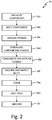
- FIG. 2 is a flow diagram of exemplary process 36.
- the elemental components of the alloy are mixed (e.g. as individual components of refined purity or alloys thereof) (step 36a).
- the mixture is melted sufficiently to eliminate component segregation (step 36b).
- the melted mixture is atomized to form droplets of molten metal cool and solidify into powder particles (step 36c).
- the powder may be screened to restrict the ranges of powder particle sizes allowed.
- the powder is consolidated in a multi-step process involving screening and containerizing (step 36d).
- the container is compacted to consolidate the powder and the hot material is extruded (step 36e).
- the resulting extruded powder then has reached near full theoretical density of the alloy without the chemical segregation typical of larger castings.
- the extruded billet is then machined and inspected (step 36f).
- a billet of the consolidated powder may then be forged at appropriate temperatures and deformation constraints to provide a forging with the basic disc profile (step 36g).
- the forging is then heat treated in a multi-step process involving high temperature heating followed by a rapid cooling process or quench (step 36h).
- the heat treatment optimizes the characteristic gamma (y) grain size from an exemplary 10 micron or less to an exemplary 20-120 micron (with 30-60 micron being preferred).
- the final step is to machine the forging to produce a useful part (step 36i).
- the quench for the heat treatment may also form strengthening precipitates of a desired distribution of sizes and desired volume percentages. Subsequent heat treatments are used to modify these distributions to produce the requisite mechanical properties of the manufactured forging. Increased grain size is associated with good high temperature creep resistance and decreased rate of crack growth during the service of the manufactured forging. The heat treated forging is then subject to machining of the final profile and the slots.
- the alloy series described in the '175 alloy series patent forms a disc product with exceptional bore strength.
- Hybrid disc structures with '175 alloy series bores and '265 and/or '266 alloy series rim structures can provide improved performance over single-material disc structures.
- the '175 alloy series bore composition comprises about 2.6-4.8 wt. % aluminum, about 16.0-22.4 wt. % cobalt, about 6.6-14.3 wt. % chromium, about 1.9-3.9 wt. % molybdenum, about 0.9-3.0 wt. % niobium, about 1.4-3.5 wt. % tantalum, about 2.4-4.6 wt. % titanium, about 1.9-4.0 wt. % tungsten, about 0.02-0.10 wt. % boron, about 0.02-0.10 wt. % carbon, about 0.03-0.10 wt. % zirconium, and a balance of nickel and minor amounts of impurities.
- the '265 alloy series rim composition comprises about 3.10-3.75 wt. % aluminum, about 20.0-22.0 wt. % cobalt, about 9.5-11.25 wt. % chromium, about 2.8-4.2 wt. % molybdenum, about 1.6-2.4 wt. % niobium, about 4.2-6.1 wt. % tantalum, about 2.6-3.5 wt. % titanium, about 1.8-2.5 wt. % tungsten, about 0.02-0.09 wt. % boron, about 0.02-0.09 wt. % carbon, about 0.04-0.09 wt. % zirconium, and a balance of nickel and minor amounts of impurities.
- the '266 alloy series rim composition comprises about 3.2-4.1 wt. % aluminum, about 20.0-22.0 wt. % cobalt, about 8-10.5 wt. % chromium, about 2.8-3.1 wt. % molybdenum, about 1.6-2.4 wt. % niobium, about 2.5-7.3 wt. % tantalum, about 2.6-3.6 wt. % titanium, about 2.8-3.3 wt. % tungsten, about 0.02-0.09 wt. % boron, about 0.02-0.09 wt. % carbon, about 0.04-0.09 wt. % zirconium, and a balance of nickel and minor amounts of impurities.
- FIG. 3 is an exploded view of a hybrid disc structure with separate bore and rim alloy components.
- Hybrid disc structure 40 includes inboard hub section 42, inboard web section 44 and hub joining surface 46.
- Hybrid disc structure 40 further comprises outboard rim section 48, outboard web section 50 and outboard rim joining surface 52.
- Hybrid disc structure 40 may be formed by joining outboard rim section 48 to inboard hub section 44 along joining surfaces 46 and 52 by joining methods well known in the art including welding, friction welding, inertia bonding, and other methods known in the art.
- a preferred joining method is brazing, in particular, transient liquid phase (TLP) brazing.
- TLP transient liquid phase
- Advanced TLP braze alloys to join '175 hub alloys to '265 and/or '266 rim alloys to form hybrid disc structure 40 are the subject of the present disclosure.
- Prior art commercially available TLP braze alloys for superalloys are eutectic compositions of nickel, chromium, and boron, a melting point depressant. During brazing, the structure is heated to a fixed temperature exceeding the melting point of the braze alloy but not above the melting points of the two structures being joined. Maintaining the brazing temperature at a fixed temperature allows boron to defuse away from the joint and into the surrounding structure. As the braze alloy loses boron, the melting temperature increases until the braze alloy isothermally solidifies and forms a metallurgical bond.
- Prior art brazing alloys could result in a weak bond as a result of the limited diffusion of solid solution strengtheners such as niobium, titanium and tungsten and the limited formation of gamma prime as a result of limited mean free path of diffusion of large atoms such as aluminum, titanium, tantalum, and niobium.
- a preferred brazing alloy composition (e.g. for brazing superalloy disc structures) includes less than about 2.0 wt. % aluminum, about 18.0-23.0 wt. % cobalt, about 12.0-15.0 wt. % chromium, about 3.8-4.5 wt. % molybdenum, about 0.8-1.5 wt. % niobium, about 1.8-3.0 wt. % tantalum, less than about 2.0 wt. % titanium, about 2.0-3.5 wt. % tungsten, about 0.8-1.2 wt. % boron, about 0.02-0.10 wt. % carbon, about 0.03-0.06 wt. % zirconium, and a balance of nickel and minor amounts of impurities.
- a preferred brazing alloy within this range has a composition that includes less than 1.8 wt. % aluminum, about 20.0-22.0 wt. % cobalt, about 13.0-14.5 wt. % chromium, about 3.9-4.3 wt. % molybdenum, about 0.9-1.0 wt. % niobium, about 2.0-2.5 wt. % tantalum, less than about 1.95 wt. % titanium, about 2.1-3.0 wt. % tungsten, about 0.9-1.1 wt. % boron, about 0.04-0.06 wt. % carbon, about 0.04-0.06 wt. % zirconium, and a balance of nickel and minor amounts of impurities.
- a particularly preferred braze alloy within this range has a composition that includes about 21.90 wt. % cobalt, about 14.00 wt. % chromium, about 4.10 wt. % molybdenum, about 0.97 wt. % niobium, about 2.58 wt. % tantalum, about 2.26 wt. % tungsten, about 1.00 wt. % boron, about 0.05 wt. % carbon, about 0.05 wt. % zirconium, and a balance of nickel and minor amounts of impurities.
- Another particularly preferred braze alloy within this range has a composition that includes about 1.73 wt. % aluminum, about 21.10 wt. % cobalt, about 13.48 wt. % chromium, about 3.94 wt. % molybdenum, about 0.93 wt. % niobium, about 2.45 or about 2.48 wt. % tantalum, about 1.92 wt. % titanium, about 2.18 wt. % tungsten, about 1.00 wt. % boron, about 0.05 wt. % carbon, about 0.05 wt. % zirconium, and a balance of nickel and minor amounts of impurities.
- FIG. 4 is a flow diagram illustrating process 60 for forming hybrid disc structure 40 ( FIG. 3 ) by transient liquid phase brazing the invention is outlined in FIG. 4 .
- the braze alloy is prepared (step 62).
- the braze alloy may be prepared by a number of processes known in the art. A preferred process is that described in the '175 patent where the braze alloy may be formed into a powder by gas or vacuum atomization. The powder may then be formed into a paste or slurry or may be consolidated into a billet for further deformation processing into foils.
- matching joining surfaces 46 and 52 may be cleaned by procedures known to those in the art (step 64).
- braze alloy in paste, slurry, foil form or other forms known to those in the art may be applied to one or both joining surfaces.
- braze alloy in foil form is used (step 66).
- Outboard rim section 48 and inboard hub section 42 may then be assembled in a mounting fixture with joining surfaces 46 and 52 separated by braze alloy (step 68).
- Mechanical force may be applied to ensure joint integrity during brazing.
- the fixture may then be heated to a temperature greater than the melting temperature of the braze alloy but less than the melting temperature of the outboard rim section and inboard hub section under a protective atmosphere or vacuum to melt braze alloy (step 70).
- the brazing temperature may be maintained until the brazing alloy isothermally solidifies and forms a metallurgical bond.
- a nickel braze alloy (e.g. for use in the method described herein) may include in combination less than about 2.0 wt.% aluminum, about 18.0-23.0 wt.% cobalt, about 12.0-15.0 wt.% chromium, about 3.8-4.5 wt.% molybdenum, about 0.8-1.5 wt.% niobium, about 1.8-3.0 wt.% tantalum, less than about 2.0 wt.% titanium, about 2.0-3.5 wt.% tungsten, about 0.8-1.2 wt.% boron, about 0.02-0.10 wt.% carbon, about 0.03-0.06 wt.% zirconium and a balance of nickel and minor amounts of impurities.
- alloy of the preceding paragraph can optionally included, additionally and/or alternatively any, one or more of the following features, configurations and/or additional components:
- the composition may include less than about 1.8 wt.% aluminum, about 20.0-22.0 wt.% cobalt, about 13.0-14.5 wt.% chromium, about 3.9-4.3 wt.% molybdenum, about 0.9-1.0 wt.% niobium, about 2.0-2.5 wt.% tantalum, less than about 1.95 wt.% titanium, about 2.1-3.0 wt.% tungsten, about 0.9-1.1 wt.% boron, about 0.04-0.06 wt.% carbon, about 0.04-0.06 wt.% zirconium, and a balance of nickel and minor amounts of impurities.
- the composition may include about 21.90 wt.% cobalt, about 14.00 wt.% chromium, about 4.10 wt.% molybdenum, about 0.97 wt.% niobium, about 2.58 wt.% tantalum, about 2.26 wt.% tungsten about 1.00 wt.% boron, about 0.05 wt.% carbon, about 0.05 wt.% zirconium, and a balance of nickel and minor amounts of impurities.
- the composition may include about 1.73 wt.% aluminum, about 21.10 wt.% cobalt, about 13.48 wt.% chromium, about 3.94 wt.% molybdenum, about 0.93 wt.% niobium, about 2.45 or about 2.48 wt.% tantalum, about 1.92 wt.% titanium, about 2.18 wt.% tungsten, about 1.00 wt.% boron, about 0.05 wt.% carbon, about 0.05 wt.% zirconium, and a balance of nickel and minor amounts of impurities.
- the alloy may be a foil, tape, cloth, powder, or slurry.
- the alloy may be a foil.
- the foil may have a thickness of from about 1.0 mils (2.54 microns) to about 1.5 mils (38.1 microns).
- a method of joining a first superalloy component with a first joining surface to a second superalloy component with a second joining surface along the matching joining surfaces may include: forming an assembly wherein the first component and the second component are positioned such that the first and second joining surfaces are facing each other with a layer of transient liquid phase brazing alloy therebetween having the following composition: less than about 2.0 wt.% aluminum, about 18.0-23.0 wt.% cobalt, about 12.0-15.0 wt.% chromium, about 3.8-4.5 wt.% molybdenum, about 0.8-1.5 wt.% niobium, about 1.8-3.0 wt.% tantalum, less than about 2.0 wt.% titanium, about 2.0-3.5 wt.% tungsten, about 0.8-1.2 wt.% boron, about 0.02-0.10 wt.% carbon, about 0.03-0.06 wt.% zirconium, and a balance of nickel and minor amounts of im
- the method of the preceding paragraph can optionally include, additionally and/or alternatively any, one or more of the following features, configurations and/or additional components:
- the transient liquid phase brazing alloy may have the following composition: less than about 1.8 wt.% aluminum, about 20.-22.0 wt.% cobalt, about 13.0-14.5 wt.% chromium, about 3.9-4.3 wt.% molybdenum, about 0.9-1.0 wt.% niobium, about 2.0-2.5 wt.% tantalum, less than about 1.95 wt.% titanium, about 2.1-3.0 wt.% tungsten, about 0.9-1.7 wt.% boron, about 0.04-0.06 wt.% carbon, about 0.04-0.06 wt.% zirconium, and a balance of nickel and minor amounts of impurities.
- the transient liquid phase brazing alloy may have the following composition: about 21.90 wt.% cobalt, about 14.00 wt.% chromium, about 4.10 wt.% molybdenum, about 0.97 wt.% niobium, about 2.58 wt.% tantalum, about 2.26 wt.% tungsten, about 1.00 wt.% boron, about 0.05 wt.% carbon, about 0.05 wt.% zirconium, and a balance of nickel and minor amounts of impurities.
- the transient liquid phase brazing alloy may have the following composition: about 1.73 wt.% aluminum, about 21.10 wt.% cobalt, about 13.48 wt.% chromium, about 3.94 wt.% molybdenum, about 0.93 wt.% niobium, about 2.45 or about 2.48 wt.% tantalum, about 1.92 wt.% titanium, about 2.18 wt.% tungsten, about 1.00 wt.% boron, about 0.05 wt.% carbon, about 0.05 wt.% zirconium, and a balance of nickel and minor amounts of impurities.
- the transient liquid phase brazing alloy may be a foil, tape, cloth, powder, or slurry.
- the transient liquid phase brazing alloy may be a foil.
- the foil may have a thickness of from about 1.0 mils (25.4 microns) to about 1.5 mils (38.1 microns).
- the first component may be an alloy with the following composition: about 2.6-4.8 wt.% aluminum, about 16.0-22.4 wt.% cobalt, about 6.6-14-3 wt.% chromium, about 1.9-3.9 wt.% molybdenum, about 0.9-3.0 wt.% niobium, about 1.4-3.5 wt.% tantalum, about 2.4-4.6 wt.% titanium, about 1.9-4.0 wt.% tungsten, about 0.02-0.10 wt.% boron, about 0.02-0.10 wt.% carbon, about 0.03-0.10 wt.% zirconium, and a balance of nickel and minor amounts of impurities.
- the second component may be an alloy with the following composition: about 3.10-3.75 wt.% aluminum, about 20.0-22.0 wt.% cobalt, about 9.5-11.25 wt.% chromium, 2.8-4.2 wt.% molybdenum, about 1.6-2.4 wt.% niobium, about 4.2-6.1 wt.% tantalum, about 2.6-3.5 wt.% titanium, about 1.8-2.5 wt.% tungsten, about 0.02-0.09 wt.% boron, about 0.02-0.09 wt.% carbon, about 0.04-0.09 wt.% zirconium, and a balance of nickel and minor amounts of impurities.
- the second compound may be an alloy with the following composition: about 3.2-4.1 wt. % aluminum, about 20.0-22.0 wt. % cobalt, about 8-10.5 wt. % chromium, about 2.8-3.1 wt. % molybdenum, about 1.6-2.4 wt. % niobium, about 2.5-7.3 wt. % tantalum, about 2.6-3.6 wt. % titanium, about 2.8-3.3 wt. % tungsten, about 0.02-0.09 wt. % boron, about 0.02-0.09 wt. % carbon, about 0.04-0.09 wt. % zirconium, and a balance of nickel and minor amounts of impurities.
Landscapes
- Engineering & Computer Science (AREA)
- Mechanical Engineering (AREA)
- Chemical & Material Sciences (AREA)
- Materials Engineering (AREA)
- General Engineering & Computer Science (AREA)
- Metallurgy (AREA)
- Organic Chemistry (AREA)
- Powder Metallurgy (AREA)
Abstract
Description
- This disclosure relates to nickel based superalloys. In particular this disclosure relates to superalloys used in high temperature gas turbine engine components such as turbine discs and compressor discs.
- In operation, the turbine discs encounter different operating conditions radially from the center or hub portion to the exterior or rim portion. The rim is hotter than the hub and, in general, all of the operating temperatures are higher for more advanced engines. The stress conditions also vary radially, with lower stresses at the rim and higher stresses at the hub. As a result of different operating conditions, the material at the rim of the disc must exhibit good high temperature creep and stress rupture resistance as well as high temperature strength and hold time fatigue crack growth resistance. The hub region of the disc must exhibit high tensile strength at more moderate temperatures and resistance to low cycle fatigue crack growth. In the most common designs, the entire turbine disc is made of a single forged and heat treated piece of material. The alloy used in the disc is therefore selected to meet all of the material requirements discussed above.
- Exotic materials have been developed to address the demands of turbine disc use.
U.S. Patent No. 6,521,175 (the '175 patent) discloses an advanced nickel based superalloy for powder metallurgical (PM) manufacture of turbine discs. The disclosure of the '175 patent is incorporated by reference herein in its entirety. The '175 patent discloses disc alloys optimized for short time engine cycles, with disc temperatures approaching temperatures of about 1500°F (816°C).U.S. Pat. App. Pub. 2010/0008790 discloses a nickel based disc alloy having a relatively high concentration of tantalum coexisting with a relatively high concentration of one or more other components. Other disc alloys are disclosed inU.S. Patent No. 5,104,614 ,U.S. Patent No. 5,662,749 ,U.S. Patent No. 6,908,519 ,EP 1,201,777 , andEP 1,195,446 . - It is advantageous in some instances to use different materials for a disc hub and rim to maximize performance.
- A nickel braze alloy may include less than about 2.0 wt. % aluminum, about 18.0-23.0 wt. % cobalt, about 12.0-15.0 wt. % chromium, about 3.8-4.5 wt. % molybdenum, about 0.8-1.5 wt. % niobium, about 1.8-3.0 wt. % tantalum, less than about 2.0 wt. % titanium, about 2.0-3.5 wt. % tungsten, about 0.8-1.2 wt. % boron, about 0.02-0.10 wt. % carbon, about 0.03-0.06 wt. % zirconium, and a balance of nickel and minor amounts of impurities.
- In an embodiment a method of joining a first superalloy component with a first joining surface to a second superalloy component with a second joining surface along the matching joining surfaces includes forming an assembly wherein the first component and the second component are positioned such that the first and second joining surfaces face each other with a layer of transient liquid phase brazing alloy therebetween (e.g. an alloy as described herein) having with the following composition: less than about 2.0 wt. % aluminum, about 18.0-23.0 wt. % cobalt, about 12.0-15.0 wt. % chromium, about 3.8-4.5 wt. % molybdenum, about 0.8-1.5 wt. % niobium, about 1.8-3.0 wt. % tantalum, less than about 2.0 wt. % titanium, about 2.0-3.5 wt. % tungsten, about 0.8-1.2 wt. % boron, about 0.02-0.10 wt. % carbon, about 0.03-0.06 wt. % zirconium, and a balance of nickel and minor amounts of impurities on the first and/or second joining surfaces. The assembly is then heated to a predetermined temperature such that the transient liquid phase brazing alloy melts and the first and second superalloy joining surfaces do not melt. The assembly is then held at the predetermined temperature for a predetermined amount of time wherein the brazing alloy isothermally solidifies and forms a metallurgical bond between the first and second superalloy components.
-
-
FIG. 1 is an exploded partial view of a gas turbine disc. -
FIG. 2 is a flow diagram of an exemplary process of forming the gas turbine disc ofFIG. 1 . -
FIG. 3 is an exploded partial view of a hybrid disc assembly according to an embodiment of the invention. -
FIG. 4 is a flow diagram of a process for forming the hybrid disc assembly ofFIG. 3 using a transient liquid phase brazing alloy according to an embodiment of the invention. -
FIG. 1 is an exploded partial view of a gas turbineengine disc assembly 20 including adisc 22 and one of a plurality ofblades 24. Thedisc 22 is generally annular, extending from an inboard bore orhub 26 at a central aperture to anoutboard rim 28. A relativelythick web 30 extends radially between thebore 26 andrim 28. The periphery of therim 28 has a circumferential array of engagement features 32 (e.g. dovetail slots) for engagingcomplementary features 34 of theblades 24. In other embodiments, the disc or blades may be a unitary structure (e.g. so called "integrally bladed" rotors or discs). - The
disc 22 may be formed by a powder metallurgical forging process (e.g., as indicated inU.S. Patent No. 6,521,175 ).FIG. 2 is a flow diagram ofexemplary process 36. The elemental components of the alloy are mixed (e.g. as individual components of refined purity or alloys thereof) (step 36a). The mixture is melted sufficiently to eliminate component segregation (step 36b). The melted mixture is atomized to form droplets of molten metal cool and solidify into powder particles (step 36c). The powder may be screened to restrict the ranges of powder particle sizes allowed. The powder is consolidated in a multi-step process involving screening and containerizing (step 36d). In the next step the container is compacted to consolidate the powder and the hot material is extruded (step 36e). The resulting extruded powder then has reached near full theoretical density of the alloy without the chemical segregation typical of larger castings. The extruded billet is then machined and inspected (step 36f). A billet of the consolidated powder may then be forged at appropriate temperatures and deformation constraints to provide a forging with the basic disc profile (step 36g). The forging is then heat treated in a multi-step process involving high temperature heating followed by a rapid cooling process or quench (step 36h). Preferably the heat treatment optimizes the characteristic gamma (y) grain size from an exemplary 10 micron or less to an exemplary 20-120 micron (with 30-60 micron being preferred). The final step is to machine the forging to produce a useful part (step 36i). - The quench for the heat treatment may also form strengthening precipitates of a desired distribution of sizes and desired volume percentages. Subsequent heat treatments are used to modify these distributions to produce the requisite mechanical properties of the manufactured forging. Increased grain size is associated with good high temperature creep resistance and decreased rate of crack growth during the service of the manufactured forging. The heat treated forging is then subject to machining of the final profile and the slots.
- The alloy series described in the '175 alloy series patent forms a disc product with exceptional bore strength. Recent alloy series described in commonly owned U.S. Pat. App. Pubs.
2013/0209265 (the '265 alloy series) and2013/02109266 - The '175 alloy series bore composition comprises about 2.6-4.8 wt. % aluminum, about 16.0-22.4 wt. % cobalt, about 6.6-14.3 wt. % chromium, about 1.9-3.9 wt. % molybdenum, about 0.9-3.0 wt. % niobium, about 1.4-3.5 wt. % tantalum, about 2.4-4.6 wt. % titanium, about 1.9-4.0 wt. % tungsten, about 0.02-0.10 wt. % boron, about 0.02-0.10 wt. % carbon, about 0.03-0.10 wt. % zirconium, and a balance of nickel and minor amounts of impurities.
- The '265 alloy series rim composition comprises about 3.10-3.75 wt. % aluminum, about 20.0-22.0 wt. % cobalt, about 9.5-11.25 wt. % chromium, about 2.8-4.2 wt. % molybdenum, about 1.6-2.4 wt. % niobium, about 4.2-6.1 wt. % tantalum, about 2.6-3.5 wt. % titanium, about 1.8-2.5 wt. % tungsten, about 0.02-0.09 wt. % boron, about 0.02-0.09 wt. % carbon, about 0.04-0.09 wt. % zirconium, and a balance of nickel and minor amounts of impurities.
- The '266 alloy series rim composition comprises about 3.2-4.1 wt. % aluminum, about 20.0-22.0 wt. % cobalt, about 8-10.5 wt. % chromium, about 2.8-3.1 wt. % molybdenum, about 1.6-2.4 wt. % niobium, about 2.5-7.3 wt. % tantalum, about 2.6-3.6 wt. % titanium, about 2.8-3.3 wt. % tungsten, about 0.02-0.09 wt. % boron, about 0.02-0.09 wt. % carbon, about 0.04-0.09 wt. % zirconium, and a balance of nickel and minor amounts of impurities.
-
FIG. 3 is an exploded view of a hybrid disc structure with separate bore and rim alloy components.Hybrid disc structure 40 includesinboard hub section 42,inboard web section 44 andhub joining surface 46.Hybrid disc structure 40 further comprisesoutboard rim section 48,outboard web section 50 and outboardrim joining surface 52.Hybrid disc structure 40 may be formed by joiningoutboard rim section 48 toinboard hub section 44 along joiningsurfaces - Advanced TLP braze alloys to join '175 hub alloys to '265 and/or '266 rim alloys to form
hybrid disc structure 40 are the subject of the present disclosure. Prior art commercially available TLP braze alloys for superalloys are eutectic compositions of nickel, chromium, and boron, a melting point depressant. During brazing, the structure is heated to a fixed temperature exceeding the melting point of the braze alloy but not above the melting points of the two structures being joined. Maintaining the brazing temperature at a fixed temperature allows boron to defuse away from the joint and into the surrounding structure. As the braze alloy loses boron, the melting temperature increases until the braze alloy isothermally solidifies and forms a metallurgical bond. - Prior art brazing alloys could result in a weak bond as a result of the limited diffusion of solid solution strengtheners such as niobium, titanium and tungsten and the limited formation of gamma prime as a result of limited mean free path of diffusion of large atoms such as aluminum, titanium, tantalum, and niobium.
- In an embodiment of the invention, a preferred brazing alloy composition (e.g. for brazing superalloy disc structures) includes less than about 2.0 wt. % aluminum, about 18.0-23.0 wt. % cobalt, about 12.0-15.0 wt. % chromium, about 3.8-4.5 wt. % molybdenum, about 0.8-1.5 wt. % niobium, about 1.8-3.0 wt. % tantalum, less than about 2.0 wt. % titanium, about 2.0-3.5 wt. % tungsten, about 0.8-1.2 wt. % boron, about 0.02-0.10 wt. % carbon, about 0.03-0.06 wt. % zirconium, and a balance of nickel and minor amounts of impurities.
- A preferred brazing alloy within this range has a composition that includes less than 1.8 wt. % aluminum, about 20.0-22.0 wt. % cobalt, about 13.0-14.5 wt. % chromium, about 3.9-4.3 wt. % molybdenum, about 0.9-1.0 wt. % niobium, about 2.0-2.5 wt. % tantalum, less than about 1.95 wt. % titanium, about 2.1-3.0 wt. % tungsten, about 0.9-1.1 wt. % boron, about 0.04-0.06 wt. % carbon, about 0.04-0.06 wt. % zirconium, and a balance of nickel and minor amounts of impurities.
- A particularly preferred braze alloy within this range has a composition that includes about 21.90 wt. % cobalt, about 14.00 wt. % chromium, about 4.10 wt. % molybdenum, about 0.97 wt. % niobium, about 2.58 wt. % tantalum, about 2.26 wt. % tungsten, about 1.00 wt. % boron, about 0.05 wt. % carbon, about 0.05 wt. % zirconium, and a balance of nickel and minor amounts of impurities.
- Another particularly preferred braze alloy within this range has a composition that includes about 1.73 wt. % aluminum, about 21.10 wt. % cobalt, about 13.48 wt. % chromium, about 3.94 wt. % molybdenum, about 0.93 wt. % niobium, about 2.45 or about 2.48 wt. % tantalum, about 1.92 wt. % titanium, about 2.18 wt. % tungsten, about 1.00 wt. % boron, about 0.05 wt. % carbon, about 0.05 wt. % zirconium, and a balance of nickel and minor amounts of impurities.
-
FIG. 4 is a flowdiagram illustrating process 60 for forming hybrid disc structure 40 (FIG. 3 ) by transient liquid phase brazing the invention is outlined inFIG. 4 . In the first step, the braze alloy is prepared (step 62). The braze alloy may be prepared by a number of processes known in the art. A preferred process is that described in the '175 patent where the braze alloy may be formed into a powder by gas or vacuum atomization. The powder may then be formed into a paste or slurry or may be consolidated into a billet for further deformation processing into foils. In preparation for joining, matching joiningsurfaces Outboard rim section 48 andinboard hub section 42 may then be assembled in a mounting fixture with joiningsurfaces - The following are non-exclusive descriptions of possible embodiments of the present invention.
- A nickel braze alloy (e.g. for use in the method described herein) may include in combination less than about 2.0 wt.% aluminum, about 18.0-23.0 wt.% cobalt, about 12.0-15.0 wt.% chromium, about 3.8-4.5 wt.% molybdenum, about 0.8-1.5 wt.% niobium, about 1.8-3.0 wt.% tantalum, less than about 2.0 wt.% titanium, about 2.0-3.5 wt.% tungsten, about 0.8-1.2 wt.% boron, about 0.02-0.10 wt.% carbon, about 0.03-0.06 wt.% zirconium and a balance of nickel and minor amounts of impurities.
- The alloy of the preceding paragraph can optionally included, additionally and/or alternatively any, one or more of the following features, configurations and/or additional components:
- The composition may include less than about 1.8 wt.% aluminum, about 20.0-22.0 wt.% cobalt, about 13.0-14.5 wt.% chromium, about 3.9-4.3 wt.% molybdenum, about 0.9-1.0 wt.% niobium, about 2.0-2.5 wt.% tantalum, less than about 1.95 wt.% titanium, about 2.1-3.0 wt.% tungsten, about 0.9-1.1 wt.% boron, about 0.04-0.06 wt.% carbon, about 0.04-0.06 wt.% zirconium, and a balance of nickel and minor amounts of impurities.
- The composition may include about 21.90 wt.% cobalt, about 14.00 wt.% chromium, about 4.10 wt.% molybdenum, about 0.97 wt.% niobium, about 2.58 wt.% tantalum, about 2.26 wt.% tungsten about 1.00 wt.% boron, about 0.05 wt.% carbon, about 0.05 wt.% zirconium, and a balance of nickel and minor amounts of impurities.
- The composition may include about 1.73 wt.% aluminum, about 21.10 wt.% cobalt, about 13.48 wt.% chromium, about 3.94 wt.% molybdenum, about 0.93 wt.% niobium, about 2.45 or about 2.48 wt.% tantalum, about 1.92 wt.% titanium, about 2.18 wt.% tungsten, about 1.00 wt.% boron, about 0.05 wt.% carbon, about 0.05 wt.% zirconium, and a balance of nickel and minor amounts of impurities.
- The alloy may be a foil, tape, cloth, powder, or slurry.
- The alloy may be a foil.
- The foil may have a thickness of from about 1.0 mils (2.54 microns) to about 1.5 mils (38.1 microns).
- A method of joining a first superalloy component with a first joining surface to a second superalloy component with a second joining surface along the matching joining surfaces may include: forming an assembly wherein the first component and the second component are positioned such that the first and second joining surfaces are facing each other with a layer of transient liquid phase brazing alloy therebetween having the following composition: less than about 2.0 wt.% aluminum, about 18.0-23.0 wt.% cobalt, about 12.0-15.0 wt.% chromium, about 3.8-4.5 wt.% molybdenum, about 0.8-1.5 wt.% niobium, about 1.8-3.0 wt.% tantalum, less than about 2.0 wt.% titanium, about 2.0-3.5 wt.% tungsten, about 0.8-1.2 wt.% boron, about 0.02-0.10 wt.% carbon, about 0.03-0.06 wt.% zirconium, and a balance of nickel and minor amounts of impurities on the first and/or second joining surfaces; heating the assembly to a predetermined temperature such that the transient liquid phase brazing alloy melts and the first and second superalloy joining surfaces do not melt; and holding the assembly at the predetermined temperature for a predetermined amount of time wherein the brazing alloy isothermally solidifies and forms a metallurgical bond between the first and second superalloy components.
- The method of the preceding paragraph can optionally include, additionally and/or alternatively any, one or more of the following features, configurations and/or additional components:
- The transient liquid phase brazing alloy may have the following composition: less than about 1.8 wt.% aluminum, about 20.-22.0 wt.% cobalt, about 13.0-14.5 wt.% chromium, about 3.9-4.3 wt.% molybdenum, about 0.9-1.0 wt.% niobium, about 2.0-2.5 wt.% tantalum, less than about 1.95 wt.% titanium, about 2.1-3.0 wt.% tungsten, about 0.9-1.7 wt.% boron, about 0.04-0.06 wt.% carbon, about 0.04-0.06 wt.% zirconium, and a balance of nickel and minor amounts of impurities.
- The transient liquid phase brazing alloy may have the following composition: about 21.90 wt.% cobalt, about 14.00 wt.% chromium, about 4.10 wt.% molybdenum, about 0.97 wt.% niobium, about 2.58 wt.% tantalum, about 2.26 wt.% tungsten, about 1.00 wt.% boron, about 0.05 wt.% carbon, about 0.05 wt.% zirconium, and a balance of nickel and minor amounts of impurities.
- The transient liquid phase brazing alloy may have the following composition: about 1.73 wt.% aluminum, about 21.10 wt.% cobalt, about 13.48 wt.% chromium, about 3.94 wt.% molybdenum, about 0.93 wt.% niobium, about 2.45 or about 2.48 wt.% tantalum, about 1.92 wt.% titanium, about 2.18 wt.% tungsten, about 1.00 wt.% boron, about 0.05 wt.% carbon, about 0.05 wt.% zirconium, and a balance of nickel and minor amounts of impurities.
- The transient liquid phase brazing alloy may be a foil, tape, cloth, powder, or slurry.
- The transient liquid phase brazing alloy may be a foil.
- The foil may have a thickness of from about 1.0 mils (25.4 microns) to about 1.5 mils (38.1 microns).
- The first component may be an alloy with the following composition: about 2.6-4.8 wt.% aluminum, about 16.0-22.4 wt.% cobalt, about 6.6-14-3 wt.% chromium, about 1.9-3.9 wt.% molybdenum, about 0.9-3.0 wt.% niobium, about 1.4-3.5 wt.% tantalum, about 2.4-4.6 wt.% titanium, about 1.9-4.0 wt.% tungsten, about 0.02-0.10 wt.% boron, about 0.02-0.10 wt.% carbon, about 0.03-0.10 wt.% zirconium, and a balance of nickel and minor amounts of impurities.
- The second component may be an alloy with the following composition: about 3.10-3.75 wt.% aluminum, about 20.0-22.0 wt.% cobalt, about 9.5-11.25 wt.% chromium, 2.8-4.2 wt.% molybdenum, about 1.6-2.4 wt.% niobium, about 4.2-6.1 wt.% tantalum, about 2.6-3.5 wt.% titanium, about 1.8-2.5 wt.% tungsten, about 0.02-0.09 wt.% boron, about 0.02-0.09 wt.% carbon, about 0.04-0.09 wt.% zirconium, and a balance of nickel and minor amounts of impurities.
- The second compound may be an alloy with the following composition: about 3.2-4.1 wt. % aluminum, about 20.0-22.0 wt. % cobalt, about 8-10.5 wt. % chromium, about 2.8-3.1 wt. % molybdenum, about 1.6-2.4 wt. % niobium, about 2.5-7.3 wt. % tantalum, about 2.6-3.6 wt. % titanium, about 2.8-3.3 wt. % tungsten, about 0.02-0.09 wt. % boron, about 0.02-0.09 wt. % carbon, about 0.04-0.09 wt. % zirconium, and a balance of nickel and minor amounts of impurities.
- While the invention has been described with reference to an exemplary embodiment(s), it will be understood by those skilled in the art that various changes may be made and equivalents may be substituted for elements thereof without departing from the scope of the invention. In addition, many modifications may be made to adapt a particular situation or material to the teachings of the invention without departing from the essential scope thereof. Therefore, it is intended that the invention not be limited to the particular embodiment(s) disclosed, but that the invention will include all embodiments falling within the scope of the appended claims.
Claims (15)
- A nickel braze alloy comprising in combination less than about 2.0 wt. % aluminum, about 18.0-23.0 wt. % cobalt, about 12.0-15.0 wt. % chromium, about 3.8-4.5 wt. % molybdenum, about 0.8-1.5 wt. % niobium, about 1.8-3.0 wt. % tantalum, less than about 2.0 wt. % titanium, about 2.0-3.5 wt. % tungsten, about 0.8-1.2 wt. % boron, about 0.02-0.10 wt. % carbon, about 0.03-0.06 wt. % zirconium, and a balance of nickel and minor amounts of impurities.
- The nickel braze alloy of claim 1, wherein the composition includes less than about 1.8 wt. % aluminum, about 20.0-22.0 wt. % cobalt, about 13.0-14.5 wt. % chromium, about 3.9-4.3 wt. % molybdenum, about 0.9-1.0 wt. % niobium, about 2.0-2.5 wt. % tantalum, less than about 1.95 wt. % titanium, about 2.1-3.0 wt. % tungsten, about 0.9-1.1 wt. % boron, about 0.04-0.06 wt. % carbon, about 0.04-0.06 wt. % zirconium, and a balance of nickel and minor amounts of impurities.
- The nickel braze alloy of claim 1, wherein the composition includes about 21.90 wt. % cobalt, about 14.00 wt. % chromium, about 4.10 wt. % molybdenum, about 0.97 wt. % niobium, about 2.58 wt. % tantalum, about 2.26 wt. % tungsten, about 1.00 wt. % boron, about 0.05 wt. % carbon, about 0.05 wt. % zirconium, and a balance of nickel and minor amounts of impurities.
- The nickel braze alloy of claim 1 or claim 2, wherein the composition includes about 1.73 wt. % aluminum, about 21.10 wt. % cobalt, about 13.48 wt. % chromium, about 3.94 wt. % molybdenum, about 0.93 wt. % niobium, about 2.48 wt. % tantalum, about 1.92 wt. % titanium, about 2.18 wt. % tungsten, about 1.00 wt. % boron, about 0.05 wt. % carbon, about 0.05 wt. % zirconium, and a balance of nickel and minor amounts of impurities.
- The nickel braze alloy of any one of the preceding claims, wherein the alloy is a foil, tape, cloth, powder, or slurry, preferably wherein the alloy is a foil.
- The nickel braze alloy of claim 5, wherein the foil has a thickness of from about 1.0 mils (25.4 microns) to about 1.5 mils (38.1 microns).
- A method of joining a first superalloy component with a first joining surface to a second superalloy component with a second joining surface along the matching joining surfaces comprises:forming an assembly wherein the first component and the second component are positioned such that the first and second joining surfaces are facing each other with a layer of transient liquid phase brazing alloy therebetween having the following composition:less than about 2.0 wt. % aluminum, about 18.0-23.0 wt. % cobalt, about 12.0-15.0 wt. % chromium, about 3.8-4.5 wt. % molybdenum, about 0.8-1.5 wt. % niobium, about 1.8-3.0 wt. % tantalum, less than about 2.0 wt. % titanium, about 2.0-3.5 wt. % tungsten, about 0.8-1.2 wt. % boron, about 0.02-0.10 wt. % carbon, about 0.03-0.06 wt. % zirconium, and a balance of nickel and minor amounts of impurities on the first and/or second joining surfaces;heating the assembly to a predetermined temperature such that the transient liquid phase brazing alloy melts and the first and second superalloy joining surfaces do not melt; andholding the assembly at the predetermined temperature for a predetermined amount of time wherein the brazing alloy isothermally solidifies and forms a metallurgical bond between the first and second superalloy components.
- The method of claim 7, wherein the transient liquid phase brazing alloy has the following composition:less than about 1.8 wt. % aluminum, about 20.0-22.0 wt. % cobalt, about 13.0-14.5 wt. % chromium, about 3.9-4.3 wt. % molybdenum, about 0.9-1.0 wt. % niobium, about 2.0-2.5 wt. % tantalum, less than about 1.95 wt. % titanium, about 2.1-3.0 wt. % tungsten, about 0.9-1.7 wt. % boron, about 0.04-0.06 wt. % carbon, about 0.04-0.06 wt. % zirconium, and a balance of nickel and minor amounts of impurities.
- The method of claim 7, wherein the transient liquid phase brazing alloy has the following composition:about 21.90 wt. % cobalt, about 14.00 wt. % chromium, about 4.10 wt. % molybdenum, about 0.97 wt. % niobium, about 2.58 wt. % tantalum, about 2.26 wt. % tungsten, about 1.00 wt. % boron, about 0.05 wt. % carbon, about 0.05 wt. % zirconium, and a balance of nickel and minor amounts of impurities.
- The method of claim 7 or claim 8, wherein the transient liquid phase brazing alloy has the following composition:about 1.73 wt. % aluminum, about 21.10 wt. % cobalt, about 13.48 wt. % chromium, about 3.94 wt. % molybdenum, about 0.93 wt. % niobium, about 2.48 wt. % tantalum, about 1.92 wt. % titanium, about 2.18 wt. % tungsten, about 1.00 wt. % boron, about 0.05 wt. % carbon, about 0.05 wt. % zirconium, and a balance of nickel and minor amounts of impurities.
- The method of any one of claims 7-10, wherein the transient liquid phase brazing alloy is a foil, tape, cloth, powder, or slurry, preferably wherein the transient liquid phase brazing alloy is a foil.
- The method of claim 11, wherein the foil has a thickness of from about 1.0 mils (25.4 microns) to about 1.5 mils (38.1 microns).
- The method of any one of claims 7-12, wherein the first component is made of an alloy with the following composition:about 2.6-4.8 wt. % aluminum, about 16.0-22.4 wt. % cobalt, about 6.6-14.3 wt. % chromium, about 1.9-3.9 wt. % molybdenum, about 0.9-3.0 wt. % niobium, about 1.4-3.5 wt. % tantalum, about 2.4-4.6 wt. % titanium, about 1.9-4.0 wt. % tungsten, about 0.02-0.10 wt. % boron, about 0.02-0.10 wt. % carbon, about 0.03-0.10 wt. % zirconium, and a balance of nickel and minor amounts of impurities.
- The method of any one of claims 7-13, wherein the second component is made of an alloy with the following composition:about 3.10-3.75 wt. % aluminum, about 20.0-22.0 wt. % cobalt, about 9.5-11.25 wt. % chromium, about 2.8-4.2 wt. % molybdenum, about 1.6-2.4 wt. % niobium, about 4.2-6.1 wt. % tantalum, about 2.6-3.5 wt. % titanium, about 1.8-2.5 wt. % tungsten, about 0.02-0.09 wt. % boron, about 0.02-0.09 wt. % carbon, about 0.04-0.09 wt. % zirconium, and a balance of nickel and minor amounts of impurities.
- The method of any one of claims 7-13, wherein the second component is made of an alloy with the following composition:about 3.2-4.1 wt. % aluminum, about 20.0-22.0 wt. % cobalt, about 8-10.5 wt. % chromium, about 2.8-3.1 wt. % molybdenum, about 1.6-2.4 wt. % niobium, about 2.5-7.3 wt. % tantalum, about 2.6-3.6 wt. % titanium, about 2.8-3.3 wt. % tungsten, about 0.02-0.09 wt. % boron, about 0.02-0.09 wt. % carbon, about 0.04-0.09 wt. % zirconium, and a balance of nickel and minor amounts of impurities.
Applications Claiming Priority (1)
| Application Number | Priority Date | Filing Date | Title |
|---|---|---|---|
| US15/095,914 US20170291265A1 (en) | 2016-04-11 | 2016-04-11 | Braze material for hybrid structures |
Publications (2)
| Publication Number | Publication Date |
|---|---|
| EP3231881A1 true EP3231881A1 (en) | 2017-10-18 |
| EP3231881B1 EP3231881B1 (en) | 2019-06-12 |
Family
ID=58009723
Family Applications (1)
| Application Number | Title | Priority Date | Filing Date |
|---|---|---|---|
| EP17155336.5A Active EP3231881B1 (en) | 2016-04-11 | 2017-02-09 | Braze material for hybrid structures |
Country Status (2)
| Country | Link |
|---|---|
| US (1) | US20170291265A1 (en) |
| EP (1) | EP3231881B1 (en) |
Families Citing this family (3)
| Publication number | Priority date | Publication date | Assignee | Title |
|---|---|---|---|---|
| DE102017219706A1 (en) * | 2017-11-07 | 2019-05-09 | Siemens Aktiengesellschaft | Boron-containing nickel / cobalt base solder with niobium and / or molybdenum, paste and method for soldering |
| US10934862B2 (en) * | 2018-08-22 | 2021-03-02 | Rolls-Royce Plc | Turbine wheel assembly |
| CN116083771B (en) * | 2022-12-28 | 2025-01-28 | 东方电气集团东方汽轮机有限公司 | Preparation and application method of a high-performance boron-free prefabricated board |
Citations (15)
| Publication number | Priority date | Publication date | Assignee | Title |
|---|---|---|---|---|
| US5104614A (en) | 1986-02-06 | 1992-04-14 | Societe Nationale D'etude Et De Construction De Moteurs D'aviation "S.N.E.C.M.A." | Superalloy compositions with a nickel base |
| WO1992013979A1 (en) * | 1991-02-07 | 1992-08-20 | Rolls-Royce Plc | Nickel base alloys for castings |
| US5662749A (en) | 1995-06-07 | 1997-09-02 | General Electric Company | Supersolvus processing for tantalum-containing nickel base superalloys |
| EP0800889A1 (en) * | 1996-04-09 | 1997-10-15 | General Electric Company | Nickel-base braze material |
| EP1195446A1 (en) | 2000-10-04 | 2002-04-10 | General Electric Company | Ni based superalloy and its use as gas turbine disks, shafts, and impellers |
| EP1201777A1 (en) | 2000-09-29 | 2002-05-02 | General Electric Company | Superalloy optimized for high-temperature performance in high-pressure turbine disks |
| EP1226896A2 (en) * | 2001-01-29 | 2002-07-31 | General Electric Company | Nickel-base braze material and braze repair method |
| US6521175B1 (en) | 1998-02-09 | 2003-02-18 | General Electric Co. | Superalloy optimized for high-temperature performance in high-pressure turbine disks |
| US6908519B2 (en) | 2002-07-19 | 2005-06-21 | General Electric Company | Isothermal forging of nickel-base superalloys in air |
| EP1623787A1 (en) * | 2004-08-03 | 2006-02-08 | Kabushiki Kaisha Toshiba | Method of repairing a stator vane of gas turbine without removing all the cracks ; repaired gas turbine |
| US20070029369A1 (en) * | 2005-08-02 | 2007-02-08 | United Technologies Corporation | Transient liquid phase bonding of dissimilar metals |
| EP2113333A2 (en) * | 2008-04-25 | 2009-11-04 | United Technologies Corporation | Nickel braze alloy composition |
| US20100008790A1 (en) | 2005-03-30 | 2010-01-14 | United Technologies Corporation | Superalloy compositions, articles, and methods of manufacture |
| US20130209266A1 (en) | 2012-02-14 | 2013-08-15 | Paul L. Reynolds | Superalloy Compositions, Articles, and Methods of Manufacture |
| US20130209265A1 (en) | 2012-02-14 | 2013-08-15 | Paul L. Reynolds | Superalloy Compositions, Articles, and Methods of Manufacture |
Family Cites Families (6)
| Publication number | Priority date | Publication date | Assignee | Title |
|---|---|---|---|---|
| US5240491A (en) * | 1991-07-08 | 1993-08-31 | General Electric Company | Alloy powder mixture for brazing of superalloy articles |
| US6165290A (en) * | 1998-05-29 | 2000-12-26 | Alliedsignal Inc. | Cobalt-chromium-palladium-based brazing alloys |
| FR2787737B1 (en) * | 1998-12-23 | 2001-01-19 | Commissariat Energie Atomique | SOLDERING COMPOSITION, METHOD FOR ASSEMBLING PARTS OF ALUMINA-BASED MATERIALS BY REFRACTORY BRAZING WITH SAID SOLDERING COMPOSITION, ASSEMBLY AND REFRACTORY JOINT THUS OBTAINED |
| US20050067061A1 (en) * | 2003-09-26 | 2005-03-31 | General Electric Company | Nickel-based braze alloy compositions and related processes and articles |
| US20110180199A1 (en) * | 2007-04-17 | 2011-07-28 | United Technologies Corporation | Powder -metallurgy braze preform and method of use |
| US20140272450A1 (en) * | 2013-03-14 | 2014-09-18 | Siemens Energy, Inc. | Near eutectic composition nickel base sandwich braze foil |
-
2016
- 2016-04-11 US US15/095,914 patent/US20170291265A1/en not_active Abandoned
-
2017
- 2017-02-09 EP EP17155336.5A patent/EP3231881B1/en active Active
Patent Citations (16)
| Publication number | Priority date | Publication date | Assignee | Title |
|---|---|---|---|---|
| US5104614A (en) | 1986-02-06 | 1992-04-14 | Societe Nationale D'etude Et De Construction De Moteurs D'aviation "S.N.E.C.M.A." | Superalloy compositions with a nickel base |
| WO1992013979A1 (en) * | 1991-02-07 | 1992-08-20 | Rolls-Royce Plc | Nickel base alloys for castings |
| US5662749A (en) | 1995-06-07 | 1997-09-02 | General Electric Company | Supersolvus processing for tantalum-containing nickel base superalloys |
| EP0800889A1 (en) * | 1996-04-09 | 1997-10-15 | General Electric Company | Nickel-base braze material |
| US6521175B1 (en) | 1998-02-09 | 2003-02-18 | General Electric Co. | Superalloy optimized for high-temperature performance in high-pressure turbine disks |
| EP1201777A1 (en) | 2000-09-29 | 2002-05-02 | General Electric Company | Superalloy optimized for high-temperature performance in high-pressure turbine disks |
| EP1195446A1 (en) | 2000-10-04 | 2002-04-10 | General Electric Company | Ni based superalloy and its use as gas turbine disks, shafts, and impellers |
| EP1226896A2 (en) * | 2001-01-29 | 2002-07-31 | General Electric Company | Nickel-base braze material and braze repair method |
| US6908519B2 (en) | 2002-07-19 | 2005-06-21 | General Electric Company | Isothermal forging of nickel-base superalloys in air |
| EP1623787A1 (en) * | 2004-08-03 | 2006-02-08 | Kabushiki Kaisha Toshiba | Method of repairing a stator vane of gas turbine without removing all the cracks ; repaired gas turbine |
| US20100008790A1 (en) | 2005-03-30 | 2010-01-14 | United Technologies Corporation | Superalloy compositions, articles, and methods of manufacture |
| US20070029369A1 (en) * | 2005-08-02 | 2007-02-08 | United Technologies Corporation | Transient liquid phase bonding of dissimilar metals |
| EP2113333A2 (en) * | 2008-04-25 | 2009-11-04 | United Technologies Corporation | Nickel braze alloy composition |
| US20130209266A1 (en) | 2012-02-14 | 2013-08-15 | Paul L. Reynolds | Superalloy Compositions, Articles, and Methods of Manufacture |
| US20130209265A1 (en) | 2012-02-14 | 2013-08-15 | Paul L. Reynolds | Superalloy Compositions, Articles, and Methods of Manufacture |
| EP2628810A1 (en) * | 2012-02-14 | 2013-08-21 | United Technologies Corporation | Superalloy compositions, articles, and methods of manufacture |
Also Published As
| Publication number | Publication date |
|---|---|
| EP3231881B1 (en) | 2019-06-12 |
| US20170291265A1 (en) | 2017-10-12 |
Similar Documents
| Publication | Publication Date | Title |
|---|---|---|
| KR101613152B1 (en) | Braze alloy for high-temperature brazing and methods for repairing or producing components using said braze alloy | |
| EP2119525B1 (en) | Method for the production of a blisk | |
| US5240491A (en) | Alloy powder mixture for brazing of superalloy articles | |
| US8918996B2 (en) | Components and processes of producing components with regions having different grain structures | |
| US6530971B1 (en) | Nickel-base braze material and braze repair method | |
| JP4240810B2 (en) | Turbine component in which a thin skin is bonded to a superalloy substrate and a method for manufacturing the same | |
| US8206117B2 (en) | Turbine components and methods of manufacturing turbine components | |
| US8801388B2 (en) | Bi-cast turbine rotor disks and methods of forming same | |
| KR101613156B1 (en) | Braze foil for high-temperature brazing and methods for repairing or producing components using said braze foil | |
| EP3421622B1 (en) | Solid-state welding of coarse grain powder metallurgy nickel-based superalloys | |
| US8480368B2 (en) | Welding process and component produced therefrom | |
| EP0836904A2 (en) | Method of repairing metallic alloy articles, such as gas turbine engine components | |
| JPH03177525A (en) | Dual alloy-made turbine disk | |
| US20100297468A1 (en) | Methods of joining and material deposition for a workpiece with a workpiece area made from a titanium-aluminide alloy | |
| KR20210054430A (en) | High gamma prime nickel based superalloy, its use, and method of manufacturing of turbine engine components | |
| CN104923956A (en) | Weld filler for nickel-base superalloys | |
| EP3231881B1 (en) | Braze material for hybrid structures | |
| US20160023439A1 (en) | Method for joining high temperature materials and articles made therewith | |
| EP3308900A1 (en) | Hybrid component and method of making | |
| US7658315B2 (en) | Process of brazing superalloy components | |
| Tazikeh et al. | Investigation of microstructure evolution of Inconel 939 joint diffusion brazed using an amorphous liquated Ni-Cr-Fe-Si-B interlayer. | |
| Stephenson | Paper 10: Cast High Temperature Materials |
Legal Events
| Date | Code | Title | Description |
|---|---|---|---|
| PUAI | Public reference made under article 153(3) epc to a published international application that has entered the european phase |
Free format text: ORIGINAL CODE: 0009012 |
|
| STAA | Information on the status of an ep patent application or granted ep patent |
Free format text: STATUS: THE APPLICATION HAS BEEN PUBLISHED |
|
| AK | Designated contracting states |
Kind code of ref document: A1 Designated state(s): AL AT BE BG CH CY CZ DE DK EE ES FI FR GB GR HR HU IE IS IT LI LT LU LV MC MK MT NL NO PL PT RO RS SE SI SK SM TR |
|
| AX | Request for extension of the european patent |
Extension state: BA ME |
|
| STAA | Information on the status of an ep patent application or granted ep patent |
Free format text: STATUS: REQUEST FOR EXAMINATION WAS MADE |
|
| 17P | Request for examination filed |
Effective date: 20180417 |
|
| RBV | Designated contracting states (corrected) |
Designated state(s): AL AT BE BG CH CY CZ DE DK EE ES FI FR GB GR HR HU IE IS IT LI LT LU LV MC MK MT NL NO PL PT RO RS SE SI SK SM TR |
|
| GRAP | Despatch of communication of intention to grant a patent |
Free format text: ORIGINAL CODE: EPIDOSNIGR1 |
|
| STAA | Information on the status of an ep patent application or granted ep patent |
Free format text: STATUS: GRANT OF PATENT IS INTENDED |
|
| RIC1 | Information provided on ipc code assigned before grant |
Ipc: B23K 35/30 20060101ALI20181123BHEP Ipc: C22C 19/05 20060101AFI20181123BHEP |
|
| INTG | Intention to grant announced |
Effective date: 20190102 |
|
| GRAS | Grant fee paid |
Free format text: ORIGINAL CODE: EPIDOSNIGR3 |
|
| GRAA | (expected) grant |
Free format text: ORIGINAL CODE: 0009210 |
|
| STAA | Information on the status of an ep patent application or granted ep patent |
Free format text: STATUS: THE PATENT HAS BEEN GRANTED |
|
| AK | Designated contracting states |
Kind code of ref document: B1 Designated state(s): AL AT BE BG CH CY CZ DE DK EE ES FI FR GB GR HR HU IE IS IT LI LT LU LV MC MK MT NL NO PL PT RO RS SE SI SK SM TR |
|
| REG | Reference to a national code |
Ref country code: GB Ref legal event code: FG4D |
|
| REG | Reference to a national code |
Ref country code: CH Ref legal event code: EP |
|
| REG | Reference to a national code |
Ref country code: AT Ref legal event code: REF Ref document number: 1142620 Country of ref document: AT Kind code of ref document: T Effective date: 20190615 |
|
| REG | Reference to a national code |
Ref country code: IE Ref legal event code: FG4D |
|
| REG | Reference to a national code |
Ref country code: DE Ref legal event code: R096 Ref document number: 602017004364 Country of ref document: DE |
|
| REG | Reference to a national code |
Ref country code: NL Ref legal event code: MP Effective date: 20190612 |
|
| REG | Reference to a national code |
Ref country code: LT Ref legal event code: MG4D |
|
| PG25 | Lapsed in a contracting state [announced via postgrant information from national office to epo] |
Ref country code: NO Free format text: LAPSE BECAUSE OF FAILURE TO SUBMIT A TRANSLATION OF THE DESCRIPTION OR TO PAY THE FEE WITHIN THE PRESCRIBED TIME-LIMIT Effective date: 20190912 Ref country code: HR Free format text: LAPSE BECAUSE OF FAILURE TO SUBMIT A TRANSLATION OF THE DESCRIPTION OR TO PAY THE FEE WITHIN THE PRESCRIBED TIME-LIMIT Effective date: 20190612 Ref country code: SE Free format text: LAPSE BECAUSE OF FAILURE TO SUBMIT A TRANSLATION OF THE DESCRIPTION OR TO PAY THE FEE WITHIN THE PRESCRIBED TIME-LIMIT Effective date: 20190612 Ref country code: FI Free format text: LAPSE BECAUSE OF FAILURE TO SUBMIT A TRANSLATION OF THE DESCRIPTION OR TO PAY THE FEE WITHIN THE PRESCRIBED TIME-LIMIT Effective date: 20190612 Ref country code: AL Free format text: LAPSE BECAUSE OF FAILURE TO SUBMIT A TRANSLATION OF THE DESCRIPTION OR TO PAY THE FEE WITHIN THE PRESCRIBED TIME-LIMIT Effective date: 20190612 Ref country code: LT Free format text: LAPSE BECAUSE OF FAILURE TO SUBMIT A TRANSLATION OF THE DESCRIPTION OR TO PAY THE FEE WITHIN THE PRESCRIBED TIME-LIMIT Effective date: 20190612 |
|
| PG25 | Lapsed in a contracting state [announced via postgrant information from national office to epo] |
Ref country code: BG Free format text: LAPSE BECAUSE OF FAILURE TO SUBMIT A TRANSLATION OF THE DESCRIPTION OR TO PAY THE FEE WITHIN THE PRESCRIBED TIME-LIMIT Effective date: 20190912 Ref country code: RS Free format text: LAPSE BECAUSE OF FAILURE TO SUBMIT A TRANSLATION OF THE DESCRIPTION OR TO PAY THE FEE WITHIN THE PRESCRIBED TIME-LIMIT Effective date: 20190612 Ref country code: LV Free format text: LAPSE BECAUSE OF FAILURE TO SUBMIT A TRANSLATION OF THE DESCRIPTION OR TO PAY THE FEE WITHIN THE PRESCRIBED TIME-LIMIT Effective date: 20190612 Ref country code: GR Free format text: LAPSE BECAUSE OF FAILURE TO SUBMIT A TRANSLATION OF THE DESCRIPTION OR TO PAY THE FEE WITHIN THE PRESCRIBED TIME-LIMIT Effective date: 20190913 |
|
| REG | Reference to a national code |
Ref country code: AT Ref legal event code: MK05 Ref document number: 1142620 Country of ref document: AT Kind code of ref document: T Effective date: 20190612 |
|
| PG25 | Lapsed in a contracting state [announced via postgrant information from national office to epo] |
Ref country code: SK Free format text: LAPSE BECAUSE OF FAILURE TO SUBMIT A TRANSLATION OF THE DESCRIPTION OR TO PAY THE FEE WITHIN THE PRESCRIBED TIME-LIMIT Effective date: 20190612 Ref country code: RO Free format text: LAPSE BECAUSE OF FAILURE TO SUBMIT A TRANSLATION OF THE DESCRIPTION OR TO PAY THE FEE WITHIN THE PRESCRIBED TIME-LIMIT Effective date: 20190612 Ref country code: EE Free format text: LAPSE BECAUSE OF FAILURE TO SUBMIT A TRANSLATION OF THE DESCRIPTION OR TO PAY THE FEE WITHIN THE PRESCRIBED TIME-LIMIT Effective date: 20190612 Ref country code: AT Free format text: LAPSE BECAUSE OF FAILURE TO SUBMIT A TRANSLATION OF THE DESCRIPTION OR TO PAY THE FEE WITHIN THE PRESCRIBED TIME-LIMIT Effective date: 20190612 Ref country code: NL Free format text: LAPSE BECAUSE OF FAILURE TO SUBMIT A TRANSLATION OF THE DESCRIPTION OR TO PAY THE FEE WITHIN THE PRESCRIBED TIME-LIMIT Effective date: 20190612 Ref country code: CZ Free format text: LAPSE BECAUSE OF FAILURE TO SUBMIT A TRANSLATION OF THE DESCRIPTION OR TO PAY THE FEE WITHIN THE PRESCRIBED TIME-LIMIT Effective date: 20190612 Ref country code: PT Free format text: LAPSE BECAUSE OF FAILURE TO SUBMIT A TRANSLATION OF THE DESCRIPTION OR TO PAY THE FEE WITHIN THE PRESCRIBED TIME-LIMIT Effective date: 20191014 |
|
| PG25 | Lapsed in a contracting state [announced via postgrant information from national office to epo] |
Ref country code: IT Free format text: LAPSE BECAUSE OF FAILURE TO SUBMIT A TRANSLATION OF THE DESCRIPTION OR TO PAY THE FEE WITHIN THE PRESCRIBED TIME-LIMIT Effective date: 20190612 Ref country code: SM Free format text: LAPSE BECAUSE OF FAILURE TO SUBMIT A TRANSLATION OF THE DESCRIPTION OR TO PAY THE FEE WITHIN THE PRESCRIBED TIME-LIMIT Effective date: 20190612 Ref country code: IS Free format text: LAPSE BECAUSE OF FAILURE TO SUBMIT A TRANSLATION OF THE DESCRIPTION OR TO PAY THE FEE WITHIN THE PRESCRIBED TIME-LIMIT Effective date: 20191012 Ref country code: ES Free format text: LAPSE BECAUSE OF FAILURE TO SUBMIT A TRANSLATION OF THE DESCRIPTION OR TO PAY THE FEE WITHIN THE PRESCRIBED TIME-LIMIT Effective date: 20190612 |
|
| REG | Reference to a national code |
Ref country code: DE Ref legal event code: R097 Ref document number: 602017004364 Country of ref document: DE |
|
| PG25 | Lapsed in a contracting state [announced via postgrant information from national office to epo] |
Ref country code: TR Free format text: LAPSE BECAUSE OF FAILURE TO SUBMIT A TRANSLATION OF THE DESCRIPTION OR TO PAY THE FEE WITHIN THE PRESCRIBED TIME-LIMIT Effective date: 20190612 |
|
| PLBE | No opposition filed within time limit |
Free format text: ORIGINAL CODE: 0009261 |
|
| STAA | Information on the status of an ep patent application or granted ep patent |
Free format text: STATUS: NO OPPOSITION FILED WITHIN TIME LIMIT |
|
| PG25 | Lapsed in a contracting state [announced via postgrant information from national office to epo] |
Ref country code: PL Free format text: LAPSE BECAUSE OF FAILURE TO SUBMIT A TRANSLATION OF THE DESCRIPTION OR TO PAY THE FEE WITHIN THE PRESCRIBED TIME-LIMIT Effective date: 20190612 Ref country code: DK Free format text: LAPSE BECAUSE OF FAILURE TO SUBMIT A TRANSLATION OF THE DESCRIPTION OR TO PAY THE FEE WITHIN THE PRESCRIBED TIME-LIMIT Effective date: 20190612 |
|
| 26N | No opposition filed |
Effective date: 20200313 |
|
| PG25 | Lapsed in a contracting state [announced via postgrant information from national office to epo] |
Ref country code: IS Free format text: LAPSE BECAUSE OF FAILURE TO SUBMIT A TRANSLATION OF THE DESCRIPTION OR TO PAY THE FEE WITHIN THE PRESCRIBED TIME-LIMIT Effective date: 20200224 Ref country code: SI Free format text: LAPSE BECAUSE OF FAILURE TO SUBMIT A TRANSLATION OF THE DESCRIPTION OR TO PAY THE FEE WITHIN THE PRESCRIBED TIME-LIMIT Effective date: 20190612 |
|
| PG2D | Information on lapse in contracting state deleted |
Ref country code: IS |
|
| REG | Reference to a national code |
Ref country code: CH Ref legal event code: PL |
|
| REG | Reference to a national code |
Ref country code: BE Ref legal event code: MM Effective date: 20200229 |
|
| PG25 | Lapsed in a contracting state [announced via postgrant information from national office to epo] |
Ref country code: MC Free format text: LAPSE BECAUSE OF FAILURE TO SUBMIT A TRANSLATION OF THE DESCRIPTION OR TO PAY THE FEE WITHIN THE PRESCRIBED TIME-LIMIT Effective date: 20190612 Ref country code: LU Free format text: LAPSE BECAUSE OF NON-PAYMENT OF DUE FEES Effective date: 20200209 |
|
| PG25 | Lapsed in a contracting state [announced via postgrant information from national office to epo] |
Ref country code: CH Free format text: LAPSE BECAUSE OF NON-PAYMENT OF DUE FEES Effective date: 20200229 Ref country code: LI Free format text: LAPSE BECAUSE OF NON-PAYMENT OF DUE FEES Effective date: 20200229 |
|
| PG25 | Lapsed in a contracting state [announced via postgrant information from national office to epo] |
Ref country code: IE Free format text: LAPSE BECAUSE OF NON-PAYMENT OF DUE FEES Effective date: 20200209 |
|
| PG25 | Lapsed in a contracting state [announced via postgrant information from national office to epo] |
Ref country code: BE Free format text: LAPSE BECAUSE OF NON-PAYMENT OF DUE FEES Effective date: 20200229 |
|
| PG25 | Lapsed in a contracting state [announced via postgrant information from national office to epo] |
Ref country code: MT Free format text: LAPSE BECAUSE OF FAILURE TO SUBMIT A TRANSLATION OF THE DESCRIPTION OR TO PAY THE FEE WITHIN THE PRESCRIBED TIME-LIMIT Effective date: 20190612 Ref country code: CY Free format text: LAPSE BECAUSE OF FAILURE TO SUBMIT A TRANSLATION OF THE DESCRIPTION OR TO PAY THE FEE WITHIN THE PRESCRIBED TIME-LIMIT Effective date: 20190612 |
|
| PG25 | Lapsed in a contracting state [announced via postgrant information from national office to epo] |
Ref country code: MK Free format text: LAPSE BECAUSE OF FAILURE TO SUBMIT A TRANSLATION OF THE DESCRIPTION OR TO PAY THE FEE WITHIN THE PRESCRIBED TIME-LIMIT Effective date: 20190612 |
|
| REG | Reference to a national code |
Ref country code: DE Ref legal event code: R081 Ref document number: 602017004364 Country of ref document: DE Owner name: RAYTHEON TECHNOLOGIES CORPORATION (N.D.GES.D.S, US Free format text: FORMER OWNER: UNITED TECHNOLOGIES CORPORATION, FARMINGTON, CONN., US Ref country code: DE Ref legal event code: R081 Ref document number: 602017004364 Country of ref document: DE Owner name: RTX CORPORATION (N.D.GES.D. STAATES DELAWARE),, US Free format text: FORMER OWNER: UNITED TECHNOLOGIES CORPORATION, FARMINGTON, CONN., US |
|
| P01 | Opt-out of the competence of the unified patent court (upc) registered |
Effective date: 20230520 |
|
| REG | Reference to a national code |
Ref country code: DE Ref legal event code: R081 Ref document number: 602017004364 Country of ref document: DE Owner name: RTX CORPORATION (N.D.GES.D. STAATES DELAWARE),, US Free format text: FORMER OWNER: RAYTHEON TECHNOLOGIES CORPORATION (N.D.GES.D.STAATES DELAWARE), ARLINGTON, VA, US |
|
| PGFP | Annual fee paid to national office [announced via postgrant information from national office to epo] |
Ref country code: GB Payment date: 20260121 Year of fee payment: 10 |
|
| PGFP | Annual fee paid to national office [announced via postgrant information from national office to epo] |
Ref country code: DE Payment date: 20260121 Year of fee payment: 10 |
|
| PGFP | Annual fee paid to national office [announced via postgrant information from national office to epo] |
Ref country code: FR Payment date: 20260121 Year of fee payment: 10 |