EP3231758A1 - Handlauf zum öffnen und schliessen von aufzugskabinenplatten - Google Patents
Handlauf zum öffnen und schliessen von aufzugskabinenplatten Download PDFInfo
- Publication number
- EP3231758A1 EP3231758A1 EP16305447.1A EP16305447A EP3231758A1 EP 3231758 A1 EP3231758 A1 EP 3231758A1 EP 16305447 A EP16305447 A EP 16305447A EP 3231758 A1 EP3231758 A1 EP 3231758A1
- Authority
- EP
- European Patent Office
- Prior art keywords
- elevator car
- car panel
- handrail
- subpanel
- locking mechanism
- Prior art date
- Legal status (The legal status is an assumption and is not a legal conclusion. Google has not performed a legal analysis and makes no representation as to the accuracy of the status listed.)
- Granted
Links
Images


Classifications
-
- B—PERFORMING OPERATIONS; TRANSPORTING
- B66—HOISTING; LIFTING; HAULING
- B66B—ELEVATORS; ESCALATORS OR MOVING WALKWAYS
- B66B11/00—Main component parts of lifts in, or associated with, buildings or other structures
- B66B11/02—Cages, i.e. cars
- B66B11/0226—Constructional features, e.g. walls assembly, decorative panels, comfort equipment, thermal or sound insulation
- B66B11/0246—Maintenance features
-
- B—PERFORMING OPERATIONS; TRANSPORTING
- B66—HOISTING; LIFTING; HAULING
- B66B—ELEVATORS; ESCALATORS OR MOVING WALKWAYS
- B66B11/00—Main component parts of lifts in, or associated with, buildings or other structures
- B66B11/02—Cages, i.e. cars
- B66B11/0226—Constructional features, e.g. walls assembly, decorative panels, comfort equipment, thermal or sound insulation
- B66B11/0253—Fixation of wall panels
Definitions
- the subject matter disclosed herein generally relates to elevator car panels and, more particularly, to methods and apparatus for opening and closing elevator car panels.
- Elevator lift manufacturers have been required to reduce hoistway or elevator shaft overhead dimensions and pit depth based on safety factors and other considerations.
- the two dimensions (overhead dimension and pit depth, also referred to collectively as safety volumes) are key characteristics for elevator construction and design.
- Mechanics currently go to the top of car, or on top thereof, or in the pit, for inspection or maintenance activity of various components of an elevator car.
- safety spaces or volumes are employed within the elevator shaft and thus require increased overhead and pit dimensions.
- the safety volumes of an elevator shaft may impact the dimensions and construction of a building that houses the elevator.
- the required dimensions of the safety volumes on the top of the car and in the pit may be increased to provide safety to technicians located in either volume during maintenance, inspection, etc. Accordingly, the hoistway dimensions may be increased, which may not be desirable for overall building construction and design. As such, solutions to ensure the safety of technicians or other persons may be desirable.
- an elevator car panel is configured to open.
- the elevator car panel includes a handrail configured on a first side of the elevator car panel and a locking mechanism configured on a second side of the elevator car panel, the second side opposite the first side.
- the handrail is operably connected to the locking mechanism such that movement of the handrail from a first position to a second position operates the locking mechanism to transition from a locked position to an unlocked position and, when in the unlocked position, the elevator car panel is openable.
- further embodiments of the elevator car panel may include that the locking mechanism includes at least one locking pin, the locking pin configured to be engaged with a fixed portion of the elevator car when the locking mechanism is in the locked position and disengaged when the locking mechanism is in the unlocked position.
- further embodiments of the elevator car panel may include a pivot operably connected to the handrail, wherein the at least one locking pin is operably connected to the pivot.
- further embodiments of the elevator car panel may include a connector operably connecting the at least one locking pin to the pivot.
- further embodiments of the elevator car panel may include a securing mechanism configured to secure the handrail in the first position and releasable to enable the handrail to move to the second position.
- further embodiments of the elevator car panel may include an additional handrail fixedly connected to the elevator car panel.
- further embodiments of the elevator car panel may include that the elevator car panel includes a first subpanel and a second subpanel, wherein the handrail connected to the locking mechanism is mounted on the first subpanel, and the first subpanel and the second subpanel form a wall of an elevator car.
- further embodiments of the elevator car panel may include at least one hinge configured to enable the elevator car panel to open when the locking mechanism is in the unlocked position.
- further embodiments of the elevator car panel may include at least one translating mechanism configured to enable the elevator car panel to open when the locking mechanism is in the unlocked position.
- a method of opening an elevator car panel includes operating a handrail of an elevator car panel from a first position to a second position and unlocking at least one locking pin of a locking mechanism operably connected to the handrail due to operation of the handrail from the first position to the second position, the at least one locking pin engageable with a fixed portion of the elevator car.
- the handrail is on a first side of the elevator car panel and the locking mechanism is on a second side of the elevator car panel opposite the first side.
- further embodiments of the method may include unlocking the handrail prior to operating the handrail from the first position to the second position.
- further embodiments of the method may include opening the elevator car panel after unlocking the at least one locking pin.
- further embodiments of the method may include operating the handrail from the second position back to the first position, and locking the at least one locking pin.
- further embodiments of the method may include that operation of the handrail comprises one of rotation, pushing, pulling, or translating.
- further embodiments of the method may include that the elevator car panel includes a first subpanel and a second subpanel, wherein the handrail connected to the locking mechanism is mounted on the first subpanel, and the first subpanel and the second subpanel form a wall of an elevator car.
- inventions of the present disclosure include a movable handrail operably connected to a locking mechanism such that movement of the handrail enables unlocking of the locking mechanism to enable opening of an elevator car panel or a portion thereof.
- FIG. 1 is a perspective view of an elevator system 101 including an elevator car 103, a counterweight 105, a roping 107, a guide rail 109, a machine 111, a position encoder 113, and a controller 115.
- the elevator car 103 and counterweight 105 are connected to each other by the roping 107.
- the roping 107 may include or be configured as, for example, ropes, steel cables, and/or coated-steel belts.
- the counterweight 105 is configured to balance a load of the elevator car 103 and is configured to facilitate movement of the elevator car 103 concurrently and in an opposite direction with respect to the counterweight 105 within an elevator shaft 117 and along the guide rail 109.
- the roping 107 engages the machine 111, which is part of an overhead structure of the elevator system 101.
- the machine 111 is configured to control movement between the elevator car 103 and the counterweight 105.
- the position encoder 113 may be mounted on an upper sheave of a speed-governor system 119 and may be configured to provide position signals related to a position of the elevator car 103 within the elevator shaft 117. In other embodiments, the position encoder 113 may be directly mounted to a moving component of the machine 111, or may be located in other positions and/or configurations as known in the art.
- the controller 115 is located, as shown, in a controller room 121 of the elevator shaft 117 and is configured to control the operation of the elevator system 101, and particularly the elevator car 103.
- the controller 115 may provide drive signals to the machine 111 to control the acceleration, deceleration, leveling, stopping, etc. of the elevator car 103.
- the controller 115 may also be configured to receive position signals from the position encoder 113.
- the elevator car 103 may stop at one or more landings 125 as controlled by the controller 115.
- the controller 115 can be located and/or configured in other locations or positions within the elevator system 101.
- the machine 111 may include a motor or similar driving mechanism.
- the machine 111 is configured to include an electrically driven motor.
- the power supply for the motor may be any power source, including a power grid, which, in combination with other components, is supplied to the motor.
- FIG. 1 is merely a non-limiting example presented for illustrative and explanatory purposes.
- a technician or other person may gain access to elements that are located behind a panel of the elevator car. For example, certain electronics and/or other components of the elevator car are stored behind a panel of the elevator car. Further, it may be necessary for a technician or other person to access exterior components of the elevator, such as governors, guide rails, roping, etc.
- FIGS. 2A and 2B schematic illustrations of an elevator car panel 200 that may be configured to employ embodiments described herein is shown.
- FIG. 2A shows a front elevation schematic view of a first side of the elevator car panel 200.
- FIG. 2B shows a rear perspective schematic view of a second side of the elevator car panel 200.
- the elevator car panel 200 includes two subpanels 202, 204, wherein a first subpanel 202 forms about a third of the elevator car panel 200 and the second subpanel 204 forms about two-thirds of the elevator car panel 200. That is, the first subpanel 202 and the second subpanel 204 are configured to form a wall of an elevator car.
- the two subpanels 202, 204 in some configurations, are parts of a solid or continuous elevator car panel, and thus are fixedly connected or are subparts of a continuous wall.
- the first subpanel 202 includes an associated first handrail 206 on a first side of the first subpanel 202 (e.g., a front or interior side of the first subpanel).
- the second subpanel 204 includes an associated second handrail 208 on a first side of the second subpanel 204 (e.g., a front or interior side of the second subpanel).
- the handrails 206, 208 are configured within the elevator car, and on the elevator car panel 200, to provide users or passengers of the elevator to have a hand rail to provide support or other function.
- the second subpanel 204 includes an operation or control section 210.
- the control section 210 includes a number of buttons that are used to enable a passenger to select a destination floor, and may also include emergency buttons, or other buttons as known in the art.
- the control section 210 may be a touchscreen or other type of user-interface display that enables a user or passenger to interact with and/or control the elevator.
- control section electronics 210a are shown on the back side of the second subpanel 204.
- the control section electronics 210a are electronics and other components that are configured to enable the control section 210 to control the elevator car.
- the control section electronics 210a may include switches, processors, communication devices, etc. that enable a passenger to control the elevator car.
- the second subpanel 204 includes a display 212.
- the display 212 is a screen or other light up display that is used to indicate a current floor or movement of the elevator car.
- the display 212 can be used to display real-time information (e.g., weather, etc.) and/or may be used to display television, advertisements, etc.
- display electronics 212a are shown on the back side of the second subpanel 204.
- the display electronics 212a may include processors, memory, display components, etc. that enable the display 212 to provide desired information, including current floor, movement, commercials, etc., as noted above.
- the elevator car panel 200 extends from a floor 214 at a bottom 216 up to a top 218, which may be a ceiling of the elevator car.
- the elevator car panel 200 may be substantially solid. That is, the elevator car panel 200 may be configured to be a wall or other structure that prevents unauthorized persons to gain access to the electronics 210a, 212a, or other components that may be located behind the elevator car panel 200. As such, as viewed from inside an elevator car, the elevator car panel 200 may appear as a solid wall that may not be opened.
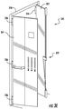
- FIG. 3A is a front elevation schematic of a first side of an elevator car panel 300 incorporating an embodiment of the present disclosure, in a first or locked position.
- FIG. 3B is a rear elevation schematic of a second side of the elevator car panel 300 of FIG. 3A , in the first position.
- FIG. 3C is a front elevation schematic of the elevator car panel 300 shown in a second or unlocked position.
- FIG. 3D is a rear elevation schematic of the elevator car panel 300 shown in the second position.
- FIG. 3E is a perspective schematic illustration of the elevator car panel 300 in a third or open position.
- the elevator car panel 300 is configured similar to that shown in FIGS. 2A-2B .
- the elevator car panel 300 includes a first subpanel 302 (with a first handrail 306 on a first side (e.g., front or interior side)) and a second subpanel 304 (with a second handrail 308 on a first side (e.g., front or interior side)).
- Located on the second subpanel 304 are a control section 310 (and associated electronics 310a) and a display 312 (and associated electronics 312a).
- the elevator car panel 300 extends from the floor 314 at the bottom 316 to the ceiling 320 at the top 318.
- a locking mechanism 322 is configured on the second side of the elevator car panel 300 (e.g., rear or exterior side).
- the locking mechanism 322 is configured to enable unlocking of the elevator car panel 300 such that the elevator car panel 300 may be opened and access to the electronics 310a, 312a and/or other components and/or features behind the elevator car panel 300, including but not limited to exterior components of the elevator such as governors, roping, guide rails, etc. is enabled.
- the locking mechanism 322 is configured to engage with a fixed portion of the elevator car when in the locked position (e.g., ceiling 320, floor 314, elevator car frame, etc.).
- the locking mechanism 322 is operably connected to the first handrail 306.
- the first handrail 306 has a first end 324 and a second end 326.
- the first end 324 is removably attached to the first subpanel 302 and the second end 326 is rotatably attached to the first subpanel 302.
- the second end 326 of the first handrail 306 is operably connected to a pivot 328 of the locking mechanism 322.
- the second end 326 is rigidly or fixedly connected to the pivot 328.
- the handrail or a portion thereof may translate, pull out, push in, slide, or otherwise move and act upon a pivot similar to that shown and described herein.
- the pivot 328 is operably connected to one or more locking pins 330a, 330b.
- a first locking pin 330a is located at the top 318 of the elevator car panel 300 and a second locking pin 330b is located at the bottom 316 of the elevator car panel 300.
- the pivot 328 is operably connected to the locking pins 330a, 330b by respective connectors 332a, 332b.
- the connectors in some embodiments, are configured as rigid rods and in other embodiments are chains (e.g., monostable, springs, etc.), although other types of connectors, rigid or otherwise, may be used without departing from the scope of the present disclosure.
- FIG. 3B shows the locking mechanism 322 (and the elevator car panel 300) in a first or locked position.
- the first locking pin 330a is engaged with the ceiling 320 such that the first locking pin 330a retains the first subpanel 302 in a closed position at the top thereof.
- the second locking pin 330b is engaged with the floor 314 such that the second locking pin 330b retains the first subpanel 302 in a closed position at the bottom thereof.
- a person cannot access the components that are behind the elevator car panel 300.
- FIGS. 3C-3D show the locking mechanism 322 in the second or unlocked position, and the arrows on the figures demonstrate how the locking mechanism 322 transitions from the first position ( FIGS. 3A-3B ) to the second position ( FIGS. 3C-3D ).
- the first handrail 306 is shown rotated about the second end 326, as indicated by the arrow.
- the first end 324 is detached from the first subpanel 302.
- the first end 324 may be fastened to the first subpanel 302 by a securing mechanism 333, e.g., a fastener, which engages with an aperture 334 in the first subpanel 302.
- the securing mechanism 333 may be screw, hidden screw, no-head screw, or other type of threaded engagement and fastening.
- Alternative mechanisms of securing, fastening, and/or attachment at the first end 324 can be used without departing from the scope of the present disclosure.
- the securing mechanism 333 can be configured as a key-lock type mechanism, magnetic locks, slot-pin engagements, localization pin, etc. that may be used to engage or secure the first end 324 of the first handrail 306 to the first subpanel 302.
- the pivot 328 As shown in FIG. 3D , as the first handrail 306 is rotated (e.g., FIG. 3C ) the pivot 328 is rotated (as indicated by the arrows in FIG. 3D ). As the pivot 328 rotates it pulls on the connectors 332a, 332b. As shown, when the pivot 328 rotates it pulls downward on the first connector 332a and thus pulls downward on the first locking pin 330a. Similarly, when the pivot 328 rotates it pulls upward on the second connector 332b and thus pulls upward on the second locking pin 330b. As shown, the first and second locking pins 330a, 330b disengage from the ceiling 320 and the floor 314, respectively, thereby unlocking the locking mechanism 322 and thus unlocking the first subpanel 302.
- the elevator car panel 300 may be opened.
- a third or open position of the elevator car panel 300 is shown.
- the first subpanel 302 and the second subpanel 304 may each be mounted on hinges 336 or other mechanisms that enable the subpanels 302, 304 to open outward or into the elevator car.
- a technician or other person has access to various components that are housed behind the elevator car panel 300 (e.g., electronics 310a, 312a, or other components located in the elevator shaft).
- the reverse process may be performed such that the subpanels 302, 304 are closed, and the first handrail 306 can be returned to the configuration shown in FIG. 3A .
- the pivot 328 is rotated to push the locking pins 330a, 330b to reengage with the ceiling 320 and the floor 314, respectively.
- the fastener 333 can be used to reengage the first end 324 of the first handrail 306 with the aperture 334 and thus secure the elevator car panel 300 in the first or locked position.
- a single locking pin can be used. That is, one or more locking pins may be used to secure one or more parts of the elevator car panel into a locked position. Further, in some embodiments, a locking pin may be configured to secure the first subpanel 302 to the second subpanel 304. Further, although shown with the locking pins at the top and bottom, other configurations having the locking pins at the sides (or combinations thereof) are contemplated herein.
- the first handrail is configured with the locking mechanism.
- the second handrail may be configured with a locking mechanism similar to that described above. Further, in some embodiments, each subpanel of an elevator car panel may be configured with a locking mechanism as described herein.
- FIGS. 3A-3E operation and/or opening of the elevator car panel and/or subpanels may be different than that shown in FIGS. 3A-3E . That is, although shown in FIGS. 3A-3E with the subpanels being hinged, other configurations are contemplated and may be used without departing from the scope of the present disclosure.
- FIGS. 4A-4C show an alternative configuration of an elevator car panel in accordance with the present disclosure.
- the elevator car panel 400 may be configured as a single panel that spans a full wall of an elevator car.
- the elevator car panel 400 is moveably mounted to a frame of the elevator car by one or more translating devices 438a, 438b.
- a first translating device 438a is configured at the top of the elevator car panel 400
- a second translating device 438b is configured at the bottom of the elevator car panel 400.
- the elevator car panel 400 also includes a locking mechanism 422 similar to that described above. However, in this embodiment, rather than locking at the top and/or bottom of the elevator car panel 400, the locking mechanism 422 engages at the sides of the elevator car panel 400.
- FIG. 4A shows the elevator car panel 400 and the locking mechanism 422 in a first or locked position.
- a pivot 428 may rotate and act on connectors 432.
- the connectors 432 move with the rotation of the pivot 428 the connectors 432 pull on locking pins 430 to disengage the locking pins 430 from a locked position or engage the locking pins 430 into the locked position.
- the elevator car panel 400 may be translated or slid along the translating devices 438a, 438b such that the elevator car panel 400 is pulled outward from the wall, thus granting access to components that may be housed behind the elevator car panel 400.
- FIG. 5 a flow process for operating and opening an elevator car panel (or portion thereof) in accordance with a non-limiting embodiment of the present disclosure is shown.
- the flow process may be performed by a technician, mechanic, or other person attempting to access components that are behind the elevator car panel.
- the elevator car panel is configured with one or more locking mechanisms and operable handrail, such as in one or more of the embodiments described above, although other configurations may employ flow process 500 without departing from the scope of the present disclosure.
- a moveable or operable handrail (such as described above) is unlocked.
- the unlocking may be by unscrewing a headless screw, using a key, or other operation that is configured to disengage the moveable handrail from a locked position.
- unlocking the handrail may include unfastening a fastener. When the handrail is secured it is in a locked or first position.
- the moveable or operable handrail is moved from the first position to a second position. That is, the handrail may be rotated, slid, pushed, pulled, or otherwise moved and/or actuated.
- the movement of the handrail at block 504 unlocks locking pins of a locking mechanism.
- the locking mechanism is configured behind the elevator car panel, and thus may be configured within a wall of the elevator car.
- the elevator car panel (or a portion thereof) can be opened. Opening of the elevator car panel (or a portion thereof) enables a person to gain access to components that are behind the elevator car panel. Thus, for example, after the elevator car panel is opened, a maintenance operation may be performed.
- the elevator car panel is closed. Then, the reverse process of opening is performed. That is, at block 512 the handrail is moved from the second position back to the first position. At block 514, as the handrail is moved in block 512, the locking pins of the locking mechanism can reengage and lock the elevator car panel. Then, at block 516, the handrail may be relocked in the first position.
- flow process 500 provides a particular order of steps, this is not intended to be limiting.
- various steps may be performed in a different order and/or various steps may be performed simultaneously.
- blocks 504-508 may occur substantially simultaneously such that the movement of the handrail, the unlocking of the pins, and the opening of the elevator car panel happen at substantially the same time or in one motion or operation, without departing from the scope of the present disclosure.
- blocks 510-514 may occur substantially simultaneously, in an opposite fashion.
- embodiments described herein provide an easily openable and operable elevator car panel or subpanel that provides easy access to components behind elevator car panels from inside the elevator car. Further, advantageously, embodiments provided herein may allow for maintenance operations from inside the car (i.e., there may be no need for an operator or technician to enter an elevator shaft) because the technician may access exterior components from inside the elevator car. Moreover, advantageously, because the handrail is used to operate the locking mechanism, there is no aesthetic change to the interior of the elevator car, and specifically because of embodiments as provided herein, the handrail is not substantially affected in aesthetics and/or functionality.
Priority Applications (3)
| Application Number | Priority Date | Filing Date | Title |
|---|---|---|---|
| EP16305447.1A EP3231758B1 (de) | 2016-04-15 | 2016-04-15 | Handlauf zum öffnen und schliessen von aufzugskabinenplatten |
| US15/468,358 US10227213B2 (en) | 2016-04-15 | 2017-03-24 | Handrail used to open and close elevator car panels |
| CN201710241973.8A CN107298365B (zh) | 2016-04-15 | 2017-04-13 | 用于打开和关闭电梯轿厢面板的扶手 |
Applications Claiming Priority (1)
| Application Number | Priority Date | Filing Date | Title |
|---|---|---|---|
| EP16305447.1A EP3231758B1 (de) | 2016-04-15 | 2016-04-15 | Handlauf zum öffnen und schliessen von aufzugskabinenplatten |
Publications (2)
| Publication Number | Publication Date |
|---|---|
| EP3231758A1 true EP3231758A1 (de) | 2017-10-18 |
| EP3231758B1 EP3231758B1 (de) | 2020-01-15 |
Family
ID=55794922
Family Applications (1)
| Application Number | Title | Priority Date | Filing Date |
|---|---|---|---|
| EP16305447.1A Active EP3231758B1 (de) | 2016-04-15 | 2016-04-15 | Handlauf zum öffnen und schliessen von aufzugskabinenplatten |
Country Status (3)
| Country | Link |
|---|---|
| US (1) | US10227213B2 (de) |
| EP (1) | EP3231758B1 (de) |
| CN (1) | CN107298365B (de) |
Cited By (2)
| Publication number | Priority date | Publication date | Assignee | Title |
|---|---|---|---|---|
| EP3530604A1 (de) * | 2018-02-21 | 2019-08-28 | Otis Elevator Company | Aufzugskomponentenzugangssysteme |
| EP3564174A1 (de) * | 2018-05-03 | 2019-11-06 | Otis Elevator Company | Zu öffnende wandplatten für aufzugskabine |
Families Citing this family (12)
| Publication number | Priority date | Publication date | Assignee | Title |
|---|---|---|---|---|
| CN107074479B (zh) * | 2014-07-25 | 2019-08-23 | 奥的斯电梯公司 | 从电梯系统的轿厢内部进行电梯系统维护 |
| WO2016162710A1 (en) * | 2015-04-07 | 2016-10-13 | Otis Elevator Company | Locking system for panels of an elevator car and method of controlling access to an elevator shaft from the inside the car |
| CN107438577B (zh) * | 2015-04-09 | 2020-08-11 | 奥的斯电梯公司 | 用于进入井道的电梯轿厢壁 |
| CN107980034B (zh) * | 2015-06-19 | 2019-09-03 | 奥的斯电梯公司 | 可移除式电梯轿厢门面板 |
| JP6366847B2 (ja) * | 2015-07-23 | 2018-08-01 | 三菱電機株式会社 | エレベータのかご上手摺装置 |
| EP3210926B1 (de) * | 2016-02-23 | 2020-01-01 | Otis Elevator Company | Aufzugswartungskonsole |
| EP3309101B1 (de) * | 2016-10-17 | 2020-06-03 | Otis Elevator Company | Aufzugskabine, aufzugssystem und verfahren zur überprüfung, wartung und/oder reparatur eines aufzugssystems |
| EP3560878B1 (de) * | 2018-04-27 | 2020-10-21 | Otis Elevator Company | Aufzugsanzeigesysteme |
| EP3747818B1 (de) | 2019-06-05 | 2024-01-17 | Otis Elevator Company | Abnehmbare platte für eine aufzugplattenanordnung |
| US11427441B2 (en) | 2020-07-23 | 2022-08-30 | Otis Elevator Company | Elevator car with foldable working platform |
| CN114735571A (zh) * | 2021-01-07 | 2022-07-12 | 奥的斯电梯公司 | 用于电梯的门楣组件及电梯系统 |
| EP4286315A1 (de) * | 2022-06-03 | 2023-12-06 | Otis Elevator Company | Aufzugskabine mit beweglichem elektrokasten |
Citations (2)
| Publication number | Priority date | Publication date | Assignee | Title |
|---|---|---|---|---|
| JPH04338085A (ja) * | 1991-05-13 | 1992-11-25 | Mitsubishi Electric Corp | エレベータかご内手摺取付装置 |
| JP2005096962A (ja) * | 2003-09-26 | 2005-04-14 | Toshiba Elevator Co Ltd | エレベータかご室 |
Family Cites Families (25)
| Publication number | Priority date | Publication date | Assignee | Title |
|---|---|---|---|---|
| US4635756A (en) * | 1985-07-09 | 1987-01-13 | Westinghouse Electric Corp. | Elevator cab |
| US4711322A (en) * | 1986-05-15 | 1987-12-08 | Westinghouse Electric Corp. | Elevator cab |
| JP4130020B2 (ja) | 1998-09-07 | 2008-08-06 | 東芝エレベータ株式会社 | エレベータの制御盤開閉装置 |
| US6209931B1 (en) | 1999-02-22 | 2001-04-03 | Newell Operating Company | Multi-point door locking system |
| US6971686B2 (en) | 2000-10-19 | 2005-12-06 | Truth Hardware Corporation | Multipoint lock system |
| US7404306B2 (en) | 2004-01-29 | 2008-07-29 | Newell Operating Company | Multi-point door lock and offset extension bolt assembly |
| US20050224299A1 (en) | 2004-04-13 | 2005-10-13 | Soemardjan San A | Elevator recessed car top for refuge area |
| JP2006256823A (ja) * | 2005-03-18 | 2006-09-28 | Toshiba Elevator Co Ltd | エレベータかご室 |
| JP4792798B2 (ja) | 2005-04-13 | 2011-10-12 | 三菱電機株式会社 | エレベータの制御盤 |
| US7556126B2 (en) | 2006-08-31 | 2009-07-07 | Chiu Nan Wang | Elevator escape arrangement |
| JP2008143672A (ja) * | 2006-12-12 | 2008-06-26 | Mitsubishi Electric Corp | エレベータかご内手摺装置 |
| CH699369B1 (de) * | 2006-12-20 | 2010-02-26 | Henseler H Ag | Liftkabine mit Wartungsfenster. |
| US7878034B2 (en) | 2007-02-02 | 2011-02-01 | Hoppe Holding Ag | Locking arrangement for a hinged panel |
| CH700929B1 (de) | 2007-02-06 | 2010-11-15 | Henseler H Ag | Aus der Liftkabine wartbarer Antrieb für eine Liftkabine. |
| JP2011068428A (ja) | 2009-09-24 | 2011-04-07 | Toshiba Elevator Co Ltd | エレベータ |
| FI124982B (fi) | 2009-11-18 | 2015-04-15 | Kone Corp | Hissikorin hätäpoistumisovi |
| CN102458066A (zh) | 2010-11-02 | 2012-05-16 | 鸿富锦精密工业(深圳)有限公司 | 服务器机柜 |
| JP2013018574A (ja) * | 2011-07-08 | 2013-01-31 | Mitsubishi Electric Corp | エレベータかごの操作盤 |
| JP6194510B2 (ja) * | 2013-08-28 | 2017-09-13 | 三菱電機株式会社 | エレベータのかご室 |
| FR3014928B1 (fr) | 2013-12-13 | 2017-01-27 | Jpm Sas | Systeme de verrouillage et de deverrouillage d'un ouvrant |
| WO2015152918A1 (en) | 2014-04-02 | 2015-10-08 | Otis Elevator Company | Removable car operating panel |
| CN104724583B (zh) * | 2015-03-24 | 2017-03-08 | 苏州福特美福电梯有限公司 | 一种手扶式电梯可转动面板扶手 |
| CN107848754B (zh) * | 2015-07-09 | 2020-06-09 | 奥的斯电梯公司 | 电梯轿厢 |
| CN204778219U (zh) * | 2015-07-21 | 2015-11-18 | 苏州台菱电梯有限公司 | 一种扶手系统 |
| EP3287409A1 (de) * | 2016-08-22 | 2018-02-28 | Otis Elevator Company | Anpassbarer und funktioneller aufzugskabinenhandlauf |
-
2016
- 2016-04-15 EP EP16305447.1A patent/EP3231758B1/de active Active
-
2017
- 2017-03-24 US US15/468,358 patent/US10227213B2/en active Active
- 2017-04-13 CN CN201710241973.8A patent/CN107298365B/zh active Active
Patent Citations (2)
| Publication number | Priority date | Publication date | Assignee | Title |
|---|---|---|---|---|
| JPH04338085A (ja) * | 1991-05-13 | 1992-11-25 | Mitsubishi Electric Corp | エレベータかご内手摺取付装置 |
| JP2005096962A (ja) * | 2003-09-26 | 2005-04-14 | Toshiba Elevator Co Ltd | エレベータかご室 |
Cited By (3)
| Publication number | Priority date | Publication date | Assignee | Title |
|---|---|---|---|---|
| EP3530604A1 (de) * | 2018-02-21 | 2019-08-28 | Otis Elevator Company | Aufzugskomponentenzugangssysteme |
| EP3564174A1 (de) * | 2018-05-03 | 2019-11-06 | Otis Elevator Company | Zu öffnende wandplatten für aufzugskabine |
| US11235951B2 (en) | 2018-05-03 | 2022-02-01 | Otis Elevator Company | Openable elevator car wall panels |
Also Published As
| Publication number | Publication date |
|---|---|
| EP3231758B1 (de) | 2020-01-15 |
| US10227213B2 (en) | 2019-03-12 |
| CN107298365B (zh) | 2020-09-11 |
| US20170297870A1 (en) | 2017-10-19 |
| CN107298365A (zh) | 2017-10-27 |
Similar Documents
| Publication | Publication Date | Title |
|---|---|---|
| EP3231758B1 (de) | Handlauf zum öffnen und schliessen von aufzugskabinenplatten | |
| US11091352B2 (en) | Elevator car frame | |
| EP3560878B1 (de) | Aufzugsanzeigesysteme | |
| US20180111797A1 (en) | Elevator car wall panels | |
| CN110304528B (zh) | 电梯轿厢天花板进入系统 | |
| US11235951B2 (en) | Openable elevator car wall panels | |
| US11124385B2 (en) | Elevator access systems for elevators | |
| US20180251340A1 (en) | Accessible elevator buffer | |
| US20190233252A1 (en) | Elevator access systems for elevators | |
| US20180171661A1 (en) | Access prevention systems for locks of elevator systems | |
| US11542119B2 (en) | Elevator access systems for elevators | |
| EP3659958B1 (de) | Säulenintegrierte stufe für aufzugsanlagen | |
| EP3530604A1 (de) | Aufzugskomponentenzugangssysteme | |
| US20190210836A1 (en) | Elevator maintenance access systems | |
| US20190169000A1 (en) | Elevator car separator for divided use | |
| JP2002308554A (ja) | エレベータ | |
| CN108382945A (zh) | 电梯系统及其救援方法 | |
| JP2003104634A (ja) | エレベータ |
Legal Events
| Date | Code | Title | Description |
|---|---|---|---|
| PUAI | Public reference made under article 153(3) epc to a published international application that has entered the european phase |
Free format text: ORIGINAL CODE: 0009012 |
|
| STAA | Information on the status of an ep patent application or granted ep patent |
Free format text: STATUS: THE APPLICATION HAS BEEN PUBLISHED |
|
| AK | Designated contracting states |
Kind code of ref document: A1 Designated state(s): AL AT BE BG CH CY CZ DE DK EE ES FI FR GB GR HR HU IE IS IT LI LT LU LV MC MK MT NL NO PL PT RO RS SE SI SK SM TR |
|
| AX | Request for extension of the european patent |
Extension state: BA ME |
|
| STAA | Information on the status of an ep patent application or granted ep patent |
Free format text: STATUS: REQUEST FOR EXAMINATION WAS MADE |
|
| 17P | Request for examination filed |
Effective date: 20180418 |
|
| RBV | Designated contracting states (corrected) |
Designated state(s): AL AT BE BG CH CY CZ DE DK EE ES FI FR GB GR HR HU IE IS IT LI LT LU LV MC MK MT NL NO PL PT RO RS SE SI SK SM TR |
|
| GRAP | Despatch of communication of intention to grant a patent |
Free format text: ORIGINAL CODE: EPIDOSNIGR1 |
|
| STAA | Information on the status of an ep patent application or granted ep patent |
Free format text: STATUS: GRANT OF PATENT IS INTENDED |
|
| INTG | Intention to grant announced |
Effective date: 20190506 |
|
| GRAJ | Information related to disapproval of communication of intention to grant by the applicant or resumption of examination proceedings by the epo deleted |
Free format text: ORIGINAL CODE: EPIDOSDIGR1 |
|
| GRAP | Despatch of communication of intention to grant a patent |
Free format text: ORIGINAL CODE: EPIDOSNIGR1 |
|
| INTG | Intention to grant announced |
Effective date: 20190621 |
|
| GRAJ | Information related to disapproval of communication of intention to grant by the applicant or resumption of examination proceedings by the epo deleted |
Free format text: ORIGINAL CODE: EPIDOSDIGR1 |
|
| INTG | Intention to grant announced |
Effective date: 20190708 |
|
| GRAP | Despatch of communication of intention to grant a patent |
Free format text: ORIGINAL CODE: EPIDOSNIGR1 |
|
| INTG | Intention to grant announced |
Effective date: 20190812 |
|
| GRAS | Grant fee paid |
Free format text: ORIGINAL CODE: EPIDOSNIGR3 |
|
| GRAA | (expected) grant |
Free format text: ORIGINAL CODE: 0009210 |
|
| STAA | Information on the status of an ep patent application or granted ep patent |
Free format text: STATUS: THE PATENT HAS BEEN GRANTED |
|
| AK | Designated contracting states |
Kind code of ref document: B1 Designated state(s): AL AT BE BG CH CY CZ DE DK EE ES FI FR GB GR HR HU IE IS IT LI LT LU LV MC MK MT NL NO PL PT RO RS SE SI SK SM TR |
|
| REG | Reference to a national code |
Ref country code: CH Ref legal event code: EP Ref country code: GB Ref legal event code: FG4D |
|
| REG | Reference to a national code |
Ref country code: IE Ref legal event code: FG4D |
|
| REG | Reference to a national code |
Ref country code: DE Ref legal event code: R096 Ref document number: 602016028224 Country of ref document: DE |
|
| REG | Reference to a national code |
Ref country code: AT Ref legal event code: REF Ref document number: 1224986 Country of ref document: AT Kind code of ref document: T Effective date: 20200215 |
|
| REG | Reference to a national code |
Ref country code: NL Ref legal event code: MP Effective date: 20200115 |
|
| REG | Reference to a national code |
Ref country code: LT Ref legal event code: MG4D |
|
| PG25 | Lapsed in a contracting state [announced via postgrant information from national office to epo] |
Ref country code: RS Free format text: LAPSE BECAUSE OF FAILURE TO SUBMIT A TRANSLATION OF THE DESCRIPTION OR TO PAY THE FEE WITHIN THE PRESCRIBED TIME-LIMIT Effective date: 20200115 Ref country code: PT Free format text: LAPSE BECAUSE OF FAILURE TO SUBMIT A TRANSLATION OF THE DESCRIPTION OR TO PAY THE FEE WITHIN THE PRESCRIBED TIME-LIMIT Effective date: 20200607 Ref country code: NO Free format text: LAPSE BECAUSE OF FAILURE TO SUBMIT A TRANSLATION OF THE DESCRIPTION OR TO PAY THE FEE WITHIN THE PRESCRIBED TIME-LIMIT Effective date: 20200415 Ref country code: FI Free format text: LAPSE BECAUSE OF FAILURE TO SUBMIT A TRANSLATION OF THE DESCRIPTION OR TO PAY THE FEE WITHIN THE PRESCRIBED TIME-LIMIT Effective date: 20200115 Ref country code: NL Free format text: LAPSE BECAUSE OF FAILURE TO SUBMIT A TRANSLATION OF THE DESCRIPTION OR TO PAY THE FEE WITHIN THE PRESCRIBED TIME-LIMIT Effective date: 20200115 |
|
| PG25 | Lapsed in a contracting state [announced via postgrant information from national office to epo] |
Ref country code: SE Free format text: LAPSE BECAUSE OF FAILURE TO SUBMIT A TRANSLATION OF THE DESCRIPTION OR TO PAY THE FEE WITHIN THE PRESCRIBED TIME-LIMIT Effective date: 20200115 Ref country code: LV Free format text: LAPSE BECAUSE OF FAILURE TO SUBMIT A TRANSLATION OF THE DESCRIPTION OR TO PAY THE FEE WITHIN THE PRESCRIBED TIME-LIMIT Effective date: 20200115 Ref country code: HR Free format text: LAPSE BECAUSE OF FAILURE TO SUBMIT A TRANSLATION OF THE DESCRIPTION OR TO PAY THE FEE WITHIN THE PRESCRIBED TIME-LIMIT Effective date: 20200115 Ref country code: GR Free format text: LAPSE BECAUSE OF FAILURE TO SUBMIT A TRANSLATION OF THE DESCRIPTION OR TO PAY THE FEE WITHIN THE PRESCRIBED TIME-LIMIT Effective date: 20200416 Ref country code: BG Free format text: LAPSE BECAUSE OF FAILURE TO SUBMIT A TRANSLATION OF THE DESCRIPTION OR TO PAY THE FEE WITHIN THE PRESCRIBED TIME-LIMIT Effective date: 20200415 Ref country code: IS Free format text: LAPSE BECAUSE OF FAILURE TO SUBMIT A TRANSLATION OF THE DESCRIPTION OR TO PAY THE FEE WITHIN THE PRESCRIBED TIME-LIMIT Effective date: 20200515 |
|
| REG | Reference to a national code |
Ref country code: DE Ref legal event code: R097 Ref document number: 602016028224 Country of ref document: DE |
|
| PG25 | Lapsed in a contracting state [announced via postgrant information from national office to epo] |
Ref country code: CZ Free format text: LAPSE BECAUSE OF FAILURE TO SUBMIT A TRANSLATION OF THE DESCRIPTION OR TO PAY THE FEE WITHIN THE PRESCRIBED TIME-LIMIT Effective date: 20200115 Ref country code: RO Free format text: LAPSE BECAUSE OF FAILURE TO SUBMIT A TRANSLATION OF THE DESCRIPTION OR TO PAY THE FEE WITHIN THE PRESCRIBED TIME-LIMIT Effective date: 20200115 Ref country code: SK Free format text: LAPSE BECAUSE OF FAILURE TO SUBMIT A TRANSLATION OF THE DESCRIPTION OR TO PAY THE FEE WITHIN THE PRESCRIBED TIME-LIMIT Effective date: 20200115 Ref country code: DK Free format text: LAPSE BECAUSE OF FAILURE TO SUBMIT A TRANSLATION OF THE DESCRIPTION OR TO PAY THE FEE WITHIN THE PRESCRIBED TIME-LIMIT Effective date: 20200115 Ref country code: LT Free format text: LAPSE BECAUSE OF FAILURE TO SUBMIT A TRANSLATION OF THE DESCRIPTION OR TO PAY THE FEE WITHIN THE PRESCRIBED TIME-LIMIT Effective date: 20200115 Ref country code: ES Free format text: LAPSE BECAUSE OF FAILURE TO SUBMIT A TRANSLATION OF THE DESCRIPTION OR TO PAY THE FEE WITHIN THE PRESCRIBED TIME-LIMIT Effective date: 20200115 Ref country code: SM Free format text: LAPSE BECAUSE OF FAILURE TO SUBMIT A TRANSLATION OF THE DESCRIPTION OR TO PAY THE FEE WITHIN THE PRESCRIBED TIME-LIMIT Effective date: 20200115 Ref country code: EE Free format text: LAPSE BECAUSE OF FAILURE TO SUBMIT A TRANSLATION OF THE DESCRIPTION OR TO PAY THE FEE WITHIN THE PRESCRIBED TIME-LIMIT Effective date: 20200115 |
|
| REG | Reference to a national code |
Ref country code: AT Ref legal event code: MK05 Ref document number: 1224986 Country of ref document: AT Kind code of ref document: T Effective date: 20200115 |
|
| PLBE | No opposition filed within time limit |
Free format text: ORIGINAL CODE: 0009261 |
|
| STAA | Information on the status of an ep patent application or granted ep patent |
Free format text: STATUS: NO OPPOSITION FILED WITHIN TIME LIMIT |
|
| PG25 | Lapsed in a contracting state [announced via postgrant information from national office to epo] |
Ref country code: MC Free format text: LAPSE BECAUSE OF FAILURE TO SUBMIT A TRANSLATION OF THE DESCRIPTION OR TO PAY THE FEE WITHIN THE PRESCRIBED TIME-LIMIT Effective date: 20200115 |
|
| REG | Reference to a national code |
Ref country code: CH Ref legal event code: PL |
|
| 26N | No opposition filed |
Effective date: 20201016 |
|
| PG25 | Lapsed in a contracting state [announced via postgrant information from national office to epo] |
Ref country code: AT Free format text: LAPSE BECAUSE OF FAILURE TO SUBMIT A TRANSLATION OF THE DESCRIPTION OR TO PAY THE FEE WITHIN THE PRESCRIBED TIME-LIMIT Effective date: 20200115 Ref country code: LU Free format text: LAPSE BECAUSE OF NON-PAYMENT OF DUE FEES Effective date: 20200415 Ref country code: IT Free format text: LAPSE BECAUSE OF FAILURE TO SUBMIT A TRANSLATION OF THE DESCRIPTION OR TO PAY THE FEE WITHIN THE PRESCRIBED TIME-LIMIT Effective date: 20200115 Ref country code: CH Free format text: LAPSE BECAUSE OF NON-PAYMENT OF DUE FEES Effective date: 20200430 Ref country code: LI Free format text: LAPSE BECAUSE OF NON-PAYMENT OF DUE FEES Effective date: 20200430 |
|
| REG | Reference to a national code |
Ref country code: BE Ref legal event code: MM Effective date: 20200430 |
|
| PG25 | Lapsed in a contracting state [announced via postgrant information from national office to epo] |
Ref country code: BE Free format text: LAPSE BECAUSE OF NON-PAYMENT OF DUE FEES Effective date: 20200430 Ref country code: PL Free format text: LAPSE BECAUSE OF FAILURE TO SUBMIT A TRANSLATION OF THE DESCRIPTION OR TO PAY THE FEE WITHIN THE PRESCRIBED TIME-LIMIT Effective date: 20200115 Ref country code: SI Free format text: LAPSE BECAUSE OF FAILURE TO SUBMIT A TRANSLATION OF THE DESCRIPTION OR TO PAY THE FEE WITHIN THE PRESCRIBED TIME-LIMIT Effective date: 20200115 |
|
| GBPC | Gb: european patent ceased through non-payment of renewal fee |
Effective date: 20200415 |
|
| PG25 | Lapsed in a contracting state [announced via postgrant information from national office to epo] |
Ref country code: IE Free format text: LAPSE BECAUSE OF NON-PAYMENT OF DUE FEES Effective date: 20200415 Ref country code: GB Free format text: LAPSE BECAUSE OF NON-PAYMENT OF DUE FEES Effective date: 20200415 |
|
| PG25 | Lapsed in a contracting state [announced via postgrant information from national office to epo] |
Ref country code: TR Free format text: LAPSE BECAUSE OF FAILURE TO SUBMIT A TRANSLATION OF THE DESCRIPTION OR TO PAY THE FEE WITHIN THE PRESCRIBED TIME-LIMIT Effective date: 20200115 Ref country code: MT Free format text: LAPSE BECAUSE OF FAILURE TO SUBMIT A TRANSLATION OF THE DESCRIPTION OR TO PAY THE FEE WITHIN THE PRESCRIBED TIME-LIMIT Effective date: 20200115 Ref country code: CY Free format text: LAPSE BECAUSE OF FAILURE TO SUBMIT A TRANSLATION OF THE DESCRIPTION OR TO PAY THE FEE WITHIN THE PRESCRIBED TIME-LIMIT Effective date: 20200115 |
|
| PG25 | Lapsed in a contracting state [announced via postgrant information from national office to epo] |
Ref country code: MK Free format text: LAPSE BECAUSE OF FAILURE TO SUBMIT A TRANSLATION OF THE DESCRIPTION OR TO PAY THE FEE WITHIN THE PRESCRIBED TIME-LIMIT Effective date: 20200115 Ref country code: AL Free format text: LAPSE BECAUSE OF FAILURE TO SUBMIT A TRANSLATION OF THE DESCRIPTION OR TO PAY THE FEE WITHIN THE PRESCRIBED TIME-LIMIT Effective date: 20200115 |
|
| PGFP | Annual fee paid to national office [announced via postgrant information from national office to epo] |
Ref country code: FR Payment date: 20230321 Year of fee payment: 8 |
|
| PGFP | Annual fee paid to national office [announced via postgrant information from national office to epo] |
Ref country code: DE Payment date: 20230321 Year of fee payment: 8 |