EP3231734B1 - Automatic aeration device for oil tank - Google Patents
Automatic aeration device for oil tank Download PDFInfo
- Publication number
- EP3231734B1 EP3231734B1 EP17166229.9A EP17166229A EP3231734B1 EP 3231734 B1 EP3231734 B1 EP 3231734B1 EP 17166229 A EP17166229 A EP 17166229A EP 3231734 B1 EP3231734 B1 EP 3231734B1
- Authority
- EP
- European Patent Office
- Prior art keywords
- wall
- enclosure
- floating roof
- oil tank
- aeration device
- Prior art date
- Legal status (The legal status is an assumption and is not a legal conclusion. Google has not performed a legal analysis and makes no representation as to the accuracy of the status listed.)
- Active
Links
- 238000005273 aeration Methods 0.000 title claims description 25
- 230000002452 interceptive effect Effects 0.000 claims description 6
- 239000003570 air Substances 0.000 description 7
- 230000000694 effects Effects 0.000 description 4
- 238000007789 sealing Methods 0.000 description 4
- 239000007788 liquid Substances 0.000 description 3
- 238000000034 method Methods 0.000 description 3
- 239000010802 sludge Substances 0.000 description 3
- 239000012080 ambient air Substances 0.000 description 2
- 230000033001 locomotion Effects 0.000 description 2
- 238000012423 maintenance Methods 0.000 description 2
- 230000000712 assembly Effects 0.000 description 1
- 238000000429 assembly Methods 0.000 description 1
- 238000005260 corrosion Methods 0.000 description 1
- 230000007797 corrosion Effects 0.000 description 1
- 230000005484 gravity Effects 0.000 description 1
- 239000012263 liquid product Substances 0.000 description 1
- 239000000463 material Substances 0.000 description 1
- 239000000047 product Substances 0.000 description 1
- 230000035484 reaction time Effects 0.000 description 1
- 238000005096 rolling process Methods 0.000 description 1
- 238000009423 ventilation Methods 0.000 description 1
Images




Classifications
-
- B—PERFORMING OPERATIONS; TRANSPORTING
- B67—OPENING, CLOSING OR CLEANING BOTTLES, JARS OR SIMILAR CONTAINERS; LIQUID HANDLING
- B67D—DISPENSING, DELIVERING OR TRANSFERRING LIQUIDS, NOT OTHERWISE PROVIDED FOR
- B67D7/00—Apparatus or devices for transferring liquids from bulk storage containers or reservoirs into vehicles or into portable containers, e.g. for retail sale purposes
- B67D7/06—Details or accessories
- B67D7/32—Arrangements of safety or warning devices; Means for preventing unauthorised delivery of liquid
-
- B—PERFORMING OPERATIONS; TRANSPORTING
- B65—CONVEYING; PACKING; STORING; HANDLING THIN OR FILAMENTARY MATERIAL
- B65D—CONTAINERS FOR STORAGE OR TRANSPORT OF ARTICLES OR MATERIALS, e.g. BAGS, BARRELS, BOTTLES, BOXES, CANS, CARTONS, CRATES, DRUMS, JARS, TANKS, HOPPERS, FORWARDING CONTAINERS; ACCESSORIES, CLOSURES, OR FITTINGS THEREFOR; PACKAGING ELEMENTS; PACKAGES
- B65D90/00—Component parts, details or accessories for large containers
- B65D90/22—Safety features
- B65D90/32—Arrangements for preventing, or minimising the effect of, excessive or insufficient pressure
- B65D90/34—Venting means
-
- B—PERFORMING OPERATIONS; TRANSPORTING
- B65—CONVEYING; PACKING; STORING; HANDLING THIN OR FILAMENTARY MATERIAL
- B65D—CONTAINERS FOR STORAGE OR TRANSPORT OF ARTICLES OR MATERIALS, e.g. BAGS, BARRELS, BOTTLES, BOXES, CANS, CARTONS, CRATES, DRUMS, JARS, TANKS, HOPPERS, FORWARDING CONTAINERS; ACCESSORIES, CLOSURES, OR FITTINGS THEREFOR; PACKAGING ELEMENTS; PACKAGES
- B65D88/00—Large containers
- B65D88/34—Large containers having floating covers, e.g. floating roofs or blankets
- B65D88/40—Large containers having floating covers, e.g. floating roofs or blankets with support for aground cover
-
- B—PERFORMING OPERATIONS; TRANSPORTING
- B65—CONVEYING; PACKING; STORING; HANDLING THIN OR FILAMENTARY MATERIAL
- B65D—CONTAINERS FOR STORAGE OR TRANSPORT OF ARTICLES OR MATERIALS, e.g. BAGS, BARRELS, BOTTLES, BOXES, CANS, CARTONS, CRATES, DRUMS, JARS, TANKS, HOPPERS, FORWARDING CONTAINERS; ACCESSORIES, CLOSURES, OR FITTINGS THEREFOR; PACKAGING ELEMENTS; PACKAGES
- B65D88/00—Large containers
- B65D88/34—Large containers having floating covers, e.g. floating roofs or blankets
- B65D88/42—Large containers having floating covers, e.g. floating roofs or blankets with sealing means between cover rim and receptacle
-
- Y—GENERAL TAGGING OF NEW TECHNOLOGICAL DEVELOPMENTS; GENERAL TAGGING OF CROSS-SECTIONAL TECHNOLOGIES SPANNING OVER SEVERAL SECTIONS OF THE IPC; TECHNICAL SUBJECTS COVERED BY FORMER USPC CROSS-REFERENCE ART COLLECTIONS [XRACs] AND DIGESTS
- Y10—TECHNICAL SUBJECTS COVERED BY FORMER USPC
- Y10T—TECHNICAL SUBJECTS COVERED BY FORMER US CLASSIFICATION
- Y10T137/00—Fluid handling
- Y10T137/2931—Diverse fluid containing pressure systems
- Y10T137/3003—Fluid separating traps or vents
- Y10T137/3084—Discriminating outlet for gas
- Y10T137/309—Fluid sensing valve
- Y10T137/3099—Float responsive
-
- Y—GENERAL TAGGING OF NEW TECHNOLOGICAL DEVELOPMENTS; GENERAL TAGGING OF CROSS-SECTIONAL TECHNOLOGIES SPANNING OVER SEVERAL SECTIONS OF THE IPC; TECHNICAL SUBJECTS COVERED BY FORMER USPC CROSS-REFERENCE ART COLLECTIONS [XRACs] AND DIGESTS
- Y10—TECHNICAL SUBJECTS COVERED BY FORMER USPC
- Y10T—TECHNICAL SUBJECTS COVERED BY FORMER US CLASSIFICATION
- Y10T137/00—Fluid handling
- Y10T137/7722—Line condition change responsive valves
- Y10T137/7771—Bi-directional flow valves
- Y10T137/7772—One head and seat carried by head of another
-
- Y—GENERAL TAGGING OF NEW TECHNOLOGICAL DEVELOPMENTS; GENERAL TAGGING OF CROSS-SECTIONAL TECHNOLOGIES SPANNING OVER SEVERAL SECTIONS OF THE IPC; TECHNICAL SUBJECTS COVERED BY FORMER USPC CROSS-REFERENCE ART COLLECTIONS [XRACs] AND DIGESTS
- Y10—TECHNICAL SUBJECTS COVERED BY FORMER USPC
- Y10T—TECHNICAL SUBJECTS COVERED BY FORMER US CLASSIFICATION
- Y10T137/00—Fluid handling
- Y10T137/7722—Line condition change responsive valves
- Y10T137/7771—Bi-directional flow valves
- Y10T137/778—Axes of ports co-axial
-
- Y—GENERAL TAGGING OF NEW TECHNOLOGICAL DEVELOPMENTS; GENERAL TAGGING OF CROSS-SECTIONAL TECHNOLOGIES SPANNING OVER SEVERAL SECTIONS OF THE IPC; TECHNICAL SUBJECTS COVERED BY FORMER USPC CROSS-REFERENCE ART COLLECTIONS [XRACs] AND DIGESTS
- Y10—TECHNICAL SUBJECTS COVERED BY FORMER USPC
- Y10T—TECHNICAL SUBJECTS COVERED BY FORMER US CLASSIFICATION
- Y10T137/00—Fluid handling
- Y10T137/8593—Systems
- Y10T137/86292—System with plural openings, one a gas vent or access opening
Definitions
- the present invention relates to an aeration device and, more particularly, to an aeration device for an oil tank that is used in a gas station.
- the oil tank of a gas station is usually mounted underground and has a determined sealing effect.
- the oil tank needs to have an aeration device.
- 6 and 7 comprises a floating roof (A) mounted in an oil tank 4, a seat (B) mounted on the floating roof (A) and having a central hole (B2) which has a periphery provided with a plurality of vent holes (B1), a support post (C) extending through the central hole (B2) of the seat (B), and a cover plate (D) secured on an upper end of the support post (C).
- the floating roof (A) is moved upward or downward by the buoyancy of the oil.
- the cover plate (D) When the lower end of the support post (C) touches the bottom of the oil tank 4, the cover plate (D) is pushed upward by the support post (C) to connect the vent holes (B1) to the ambient environment so as to provide an aerating effect.
- the support post (C) has a determined weight so that it is difficult to open the cover plate (D).
- the conventional aeration device does not have a pressure regulation function.
- the cover plate (D) is easily broken when the support post (C) is inclined.
- the document WO2009017459A1 describes a vacuum break valve structure for an internal floating cover of a liquid storage tank, the vacuum break valve comprising a valve seat connected to said cover and defining an opening through said cover, a float valve not connected to the valve seat and disposed for substantially free movement under buoyancy between an open state and a closed state, wherein in the closed state the float valve contacts the valve seat and in the open state there is passageway between the float valve and the valve seat.
- This vacuum break valve structure serves to alleviate the problems which may occur with vacuum break valve structures of internal floating covers that do not close in sufficiently narrow reaction times during the refilling process of the storage tanks or that may occur with floating trap doors of internal floating covers that are inclined to weathering such as corrosion.
- the document also describes a method for preventing negative pressure buildup on an underside of an internal floating cover in a liquid storage tank by employing the vacuum break valve structure.
- the document US2007272692A1 describes a liquid storage tank that has a shell wall and a roof that has a deck with a top surface and is designed to move vertically within the wall, floating upon the surface of product stored in the tank, the tank having at least one drain on the roof with an opening spaced at a significant distance above the top surface of the deck and a structure that enables the top surface of the deck to be tilted toward the drain opening.
- the drain openings of the invention have the purpose to prevent the stored liquid product to flow up through the drains onto the deck of the roof.
- the document US2735574A describes a floating tank for use with a storage tank having upstanding side walls and a bottom wall, comprising a main section formed with an aperture, an auxiliary section normally covering said aperture, first support means for holding said main section spaced above said bottom wall when the contents of said tank are drained, second support means for holding said auxiliary section spaced above said bottom wall when the contents of said tank are drained, said support means being arranged to hold said auxiliary section at a different elevation than said main section whereby an opening will be defined therebetween.
- the main section and the auxiliary section are designed to provide a floating roof in the storage tank that permits the admission of adequate light and ventilation to the lower portion of the storage tank when the floating roof is in a lowered position.
- the document US2004232148A1 describes a slide guide assembly for a floating cover of a sludge digester tank, comprising a track having at least one surface defining an at least partially vertical guide path, said track being connected at least indirectly to one of the floating cover and the tank, at least one slider member slidably engaged with said track for motion along said path, said slider member being connected at least indirectly to the other of the floating cover and the tank, and at least one bearing strip attached to said slider member for engaging said surface of said track in a low-friction slidable contact, said bearing strip being removable from said slider member while said slide member remains in slidable engagement with said track.
- the bearing strip or strips are preferably made of a non-lubricated polymeric material.
- the document also discloses a method for repairing or maintaining a slide guide assembly for a floating cover of a sludge digester tank.
- the described invention solves especially the objective to provide a slide guide assembly for sludge digester tanks that may be more easily serviced and maintained than conventional slide guide assemblies.
- the primary objective of the present invention is to provide an automatic aeration device for an oil tank of a gas station.
- an automatic aeration device comprising a first floating roof, a second floating roof and a movable valve.
- the first floating roof has a through hole which has a periphery provided with a first enclosure extending upward vertically through a first height.
- the first enclosure has an upper end provided with a first upper flange.
- the second floating roof has a maximum area smaller than an area of the through hole of the first floating roof.
- the second floating roof has an upper face provided with a second enclosure extending upward vertically through a second height that is greater than the first height of the first enclosure.
- the second enclosure has an upper end provided with a second upper flange.
- the movable valve has a plate provided with a central hole which extends vertically through the plate.
- the plate has a lower portion provided with an outer wall and an inner wall arranged concentrically.
- the outer wall and the inner wall extend downward vertically through a determined depth.
- the outer wall has an outer diameter smaller than an inner diameter of the first enclosure and has a lower end provided with a first lower flange interfering with the first upper flange.
- the inner wall has an outer diameter smaller than an inner diameter of the second enclosure and has a lower end provided with a second lower flange interfering with the second upper flange.
- the outer wall has an upper end provided with a plurality of first vent holes.
- the inner wall has an upper end provided with a plurality of second vent holes.
- the movable valve is mounted on and covers an upper portion of the through hole of the first floating roof, with the outer wall being mounted in the first enclosure of the first floating roof, and with the inner wall being mounted in the second enclosure of the second floating roof.
- an automatic aeration device in accordance with the preferred embodiment of the present invention comprises a first floating roof 1, a second floating roof 2 and a movable valve 3.
- the automatic aeration device is mounted in an oil tank 4 to regulate automatically the air inlet and outlet and the pressure balance of the oil tank 4.
- the oil tank 4 contains oil therein and has a lower portion provided with a plurality of stop portions 41 having determined height.
- the first floating roof 1 floats on the oil level of the oil tank 4.
- the first floating roof 1 has an outer diameter slightly smaller than the inner diameter of the oil tank 4.
- a sealing ring 13 is mounted on the outer diameter of the first floating roof 1 and slidably rests on the inner wall of the oil tank 4 so that the first floating roof 1 is moved upward and downward in the oil tank 4 and has a sealing effect.
- the sealing ring 13 is made of rubber.
- the first floating roof 1 has a center provided with a through hole 11 which has a periphery provided with a first enclosure 12 extending upward vertically through a first height.
- the first enclosure 12 has an upper end provided with a first upper flange 121.
- the second floating roof 2 floats on the oil level of the oil tank 4.
- the second floating roof 2 has a maximum area smaller than an area of the through hole 11 of the first floating roof 1.
- the second floating roof 2 has an outer diameter smaller than the inner diameter of the through hole 11 of the first floating roof 1.
- the second floating roof 2 has an upper face provided with a second enclosure 21 extending upward vertically through a second height that is greater than the first height of the first enclosure 12.
- the second enclosure 21 has an upper end provided with a second upper flange 211.
- the movable valve 3 has a plate 31 provided with a central hole 310 which extends vertically through the plate 31.
- the plate 31 has a lower portion provided with an outer wall 32 and an inner wall 33 arranged concentrically.
- the outer wall 32 and the inner wall 33 extend downward vertically through a determined depth.
- the outer wall 32 and the inner wall 33 extend downward through the same depth.
- the outer wall 32 has an outer diameter smaller than an inner diameter of the first enclosure 12 and has a lower end provided with a first lower flange 322 interfering with the first upper flange 121.
- the inner wall 33 has an outer diameter smaller than an inner diameter of the second enclosure 21 and has a lower end provided with a second lower flange 332 interfering with the second upper flange 211.
- the outer wall 32 has an upper end provided with a plurality of first vent holes 321.
- the inner wall 33 has an upper end provided with a plurality of second vent holes 331.
- the movable valve 3 is mounted on and covers an upper portion of the through hole 11 of the first floating roof 1, with the outer wall 32 being mounted in the first enclosure 12 of the first floating roof 1, and with the inner wall 33 being mounted in the second enclosure 21 of the second floating roof 2.
- the first upper flange 121 extends horizontally in a direction of the inner diameter of the first enclosure 12, and the first lower flange 322 extends horizontally in a direction of the outer diameter of the outer wall 32.
- the second upper flange 211 extends horizontally in a direction of the inner diameter of the second enclosure 21, and the second lower flange 332 extends horizontally in a direction of the outer diameter of the inner wall 33.
- the automatic aeration device further comprises a plurality of balls 34 mounted between the inner diameter of the first enclosure 12 and the outer diameter of the outer wall 32, and mounted between the inner diameter of the second enclosure 21 and the outer diameter of the inner wall 33.
- the automatic aeration device is mounted in the oil tank 4, with the first floating roof 1 and the second floating roof 2 being supported by the buoyancy of the oil contained in the oil tank 4.
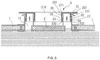
- the second floating roof 2 is pushed upward by the oil, and the second enclosure 21 is moved upward to push the plate 31 of the movable valve 3 upward by the second upper flange 211 of the second enclosure 21, so that the first vent holes 321 of the outer wall 32 are opened, and the second vent holes 331 of the inner wall 33 are closed as shown in FIG. 3 .
- the air in the oil tank 4 is forced by the oil to pass through the first vent holes 321 of the outer wall 32 and is drained outward from the first vent holes 321 of the outer wall 32 into the ambient environment as indicated by the arrows in FIG. 3 .
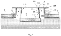
- the second floating roof 2 is moved downward to lower the second enclosure 21, so that the second upper flange 211 of the second enclosure 21 is moved downward to push the balls 34 and the second lower flange 332 of the inner wall 33.
- the inner wall 33 is moved downward to pull the plate 31 of the movable valve 3 downward, so that the first vent holes 321 of the outer wall 32 are closed, and the second vent holes 331 of the inner wall 33 are opened.
- the ambient air in introduced through the second vent holes 331 of the inner wall 33 into the oil tank 4 as indicated by the arrows.
- the balls 34 provide a rolling effect between the first enclosure 12 and the outer wall 32, and between the second enclosure 21 and the inner wall 33, to reduce the friction, thereby facilitating opening and closing of the movable valve 3.
- the automatic aeration device regulates automatically the interior pressure and the air convection of the oil tank 4, so that the oil is infused into or drawn from the oil tank 4 conveniently, without incurring a mechanically breaking problem.
- the automatic aeration device maintains the pressure balance of the oil tank 4 automatically at any moment.
- the automatic aeration device keeps the air convection between the oil tank 4 and the ambient environment, so that the oil is infused into or drawn from the oil tank 4 smoothly.
- the automatic aeration device has a structure that prevents a mechanical breaking.
Landscapes
- Engineering & Computer Science (AREA)
- Mechanical Engineering (AREA)
- Self-Closing Valves And Venting Or Aerating Valves (AREA)
- General Details Of Gearings (AREA)
- Removal Of Floating Material (AREA)
- Aeration Devices For Treatment Of Activated Polluted Sludge (AREA)
Description
- The present invention relates to an aeration device and, more particularly, to an aeration device for an oil tank that is used in a gas station.
- The oil tank of a gas station is usually mounted underground and has a determined sealing effect. However, when the oil is infused into or drawn from the oil tank, it is necessary to produce an air convection between the oil tank and the ambient environment, so that the oil can be infused into or drawn from the oil tank conveniently. Thus, the oil tank needs to have an aeration device. A conventional aeration device with a vacuum breaking function in accordance with the prior art shown in
FIGS. 6 and7 comprises a floating roof (A) mounted in anoil tank 4, a seat (B) mounted on the floating roof (A) and having a central hole (B2) which has a periphery provided with a plurality of vent holes (B1), a support post (C) extending through the central hole (B2) of the seat (B), and a cover plate (D) secured on an upper end of the support post (C). When the oil is infused into or drawn from theoil tank 4, the floating roof (A) is moved upward or downward by the buoyancy of the oil. When the lower end of the support post (C) touches the bottom of theoil tank 4, the cover plate (D) is pushed upward by the support post (C) to connect the vent holes (B1) to the ambient environment so as to provide an aerating effect. However, the support post (C) has a determined weight so that it is difficult to open the cover plate (D). Thus, the conventional aeration device does not have a pressure regulation function. In addition, when the lower end of the support post (C) hits the bottom of theoil tank 4, the cover plate (D) is easily broken when the support post (C) is inclined. - The document
WO2009017459A1 describes a vacuum break valve structure for an internal floating cover of a liquid storage tank, the vacuum break valve comprising a valve seat connected to said cover and defining an opening through said cover, a float valve not connected to the valve seat and disposed for substantially free movement under buoyancy between an open state and a closed state, wherein in the closed state the float valve contacts the valve seat and in the open state there is passageway between the float valve and the valve seat. This vacuum break valve structure serves to alleviate the problems which may occur with vacuum break valve structures of internal floating covers that do not close in sufficiently narrow reaction times during the refilling process of the storage tanks or that may occur with floating trap doors of internal floating covers that are inclined to weathering such as corrosion. The document also describes a method for preventing negative pressure buildup on an underside of an internal floating cover in a liquid storage tank by employing the vacuum break valve structure. - The document
US2007272692A1 describes a liquid storage tank that has a shell wall and a roof that has a deck with a top surface and is designed to move vertically within the wall, floating upon the surface of product stored in the tank, the tank having at least one drain on the roof with an opening spaced at a significant distance above the top surface of the deck and a structure that enables the top surface of the deck to be tilted toward the drain opening. The drain openings of the invention have the purpose to prevent the stored liquid product to flow up through the drains onto the deck of the roof. - The document
US2735574A describes a floating tank for use with a storage tank having upstanding side walls and a bottom wall, comprising a main section formed with an aperture, an auxiliary section normally covering said aperture, first support means for holding said main section spaced above said bottom wall when the contents of said tank are drained, second support means for holding said auxiliary section spaced above said bottom wall when the contents of said tank are drained, said support means being arranged to hold said auxiliary section at a different elevation than said main section whereby an opening will be defined therebetween. The main section and the auxiliary section are designed to provide a floating roof in the storage tank that permits the admission of adequate light and ventilation to the lower portion of the storage tank when the floating roof is in a lowered position. - The document
US2004232148A1 describes a slide guide assembly for a floating cover of a sludge digester tank, comprising a track having at least one surface defining an at least partially vertical guide path, said track being connected at least indirectly to one of the floating cover and the tank, at least one slider member slidably engaged with said track for motion along said path, said slider member being connected at least indirectly to the other of the floating cover and the tank, and at least one bearing strip attached to said slider member for engaging said surface of said track in a low-friction slidable contact, said bearing strip being removable from said slider member while said slide member remains in slidable engagement with said track. The bearing strip or strips are preferably made of a non-lubricated polymeric material. The document also discloses a method for repairing or maintaining a slide guide assembly for a floating cover of a sludge digester tank. The described invention solves especially the objective to provide a slide guide assembly for sludge digester tanks that may be more easily serviced and maintained than conventional slide guide assemblies. - The primary objective of the present invention is to provide an automatic aeration device for an oil tank of a gas station.
- In accordance with the present invention, there is provided an automatic aeration device according to
claim 1 comprising a first floating roof, a second floating roof and a movable valve. The first floating roof has a through hole which has a periphery provided with a first enclosure extending upward vertically through a first height. The first enclosure has an upper end provided with a first upper flange. The second floating roof has a maximum area smaller than an area of the through hole of the first floating roof. The second floating roof has an upper face provided with a second enclosure extending upward vertically through a second height that is greater than the first height of the first enclosure. The second enclosure has an upper end provided with a second upper flange. The movable valve has a plate provided with a central hole which extends vertically through the plate. The plate has a lower portion provided with an outer wall and an inner wall arranged concentrically. The outer wall and the inner wall extend downward vertically through a determined depth. The outer wall has an outer diameter smaller than an inner diameter of the first enclosure and has a lower end provided with a first lower flange interfering with the first upper flange. The inner wall has an outer diameter smaller than an inner diameter of the second enclosure and has a lower end provided with a second lower flange interfering with the second upper flange. The outer wall has an upper end provided with a plurality of first vent holes. The inner wall has an upper end provided with a plurality of second vent holes. The movable valve is mounted on and covers an upper portion of the through hole of the first floating roof, with the outer wall being mounted in the first enclosure of the first floating roof, and with the inner wall being mounted in the second enclosure of the second floating roof. - Further benefits and advantages of the present invention will become apparent after a careful reading of the detailed description with appropriate reference to the accompanying drawings.
-
-
FIG. 1 is a perspective view of an automatic aeration device in accordance with the preferred embodiment of the present invention. -
FIG. 2 is a cross-sectional assembly view showing the automatic aeration device being mounted in an oil tank. -
FIG. 3 is a cross-sectional operational view showing that the air is drained outward when the oil is infused into the oil tank. -
FIG. 4 is a cross-sectional operational view showing that the air is introduced into the oil tank when the oil is drawn from the oil tank. -
FIG. 5 is a cross-sectiona! operational view showing that the oil is drawn completely outward from the oil tank for maintenance of the oil tank. -
FIG. 6 is a cross-sectional view of a conventional aeration device with a vacuum breaking function in accordance with the prior art. -
FIG. 7 is a cross-sectional view showing operation of the conventional aeration device in accordance with the prior art. - Referring to the drawings and initially to
FIGS. 1-3 , an automatic aeration device in accordance with the preferred embodiment of the present invention comprises a first floatingroof 1, a second floatingroof 2 and amovable valve 3. - The automatic aeration device is mounted in an
oil tank 4 to regulate automatically the air inlet and outlet and the pressure balance of theoil tank 4. Theoil tank 4 contains oil therein and has a lower portion provided with a plurality ofstop portions 41 having determined height. - The first floating
roof 1 floats on the oil level of theoil tank 4. The first floatingroof 1 has an outer diameter slightly smaller than the inner diameter of theoil tank 4. Asealing ring 13 is mounted on the outer diameter of the first floatingroof 1 and slidably rests on the inner wall of theoil tank 4 so that the first floatingroof 1 is moved upward and downward in theoil tank 4 and has a sealing effect. The sealingring 13 is made of rubber. The first floatingroof 1 has a center provided with a throughhole 11 which has a periphery provided with afirst enclosure 12 extending upward vertically through a first height. Thefirst enclosure 12 has an upper end provided with a firstupper flange 121. - The second floating
roof 2 floats on the oil level of theoil tank 4. The second floatingroof 2 has a maximum area smaller than an area of the throughhole 11 of the first floatingroof 1. The second floatingroof 2 has an outer diameter smaller than the inner diameter of the throughhole 11 of the first floatingroof 1. The second floatingroof 2 has an upper face provided with asecond enclosure 21 extending upward vertically through a second height that is greater than the first height of thefirst enclosure 12. Thesecond enclosure 21 has an upper end provided with a secondupper flange 211. - The
movable valve 3 has aplate 31 provided with acentral hole 310 which extends vertically through theplate 31. Theplate 31 has a lower portion provided with anouter wall 32 and aninner wall 33 arranged concentrically. Theouter wall 32 and theinner wall 33 extend downward vertically through a determined depth. Preferably, theouter wall 32 and theinner wall 33 extend downward through the same depth. Theouter wall 32 has an outer diameter smaller than an inner diameter of thefirst enclosure 12 and has a lower end provided with a firstlower flange 322 interfering with the firstupper flange 121. Theinner wall 33 has an outer diameter smaller than an inner diameter of thesecond enclosure 21 and has a lower end provided with a secondlower flange 332 interfering with the secondupper flange 211. Theouter wall 32 has an upper end provided with a plurality of first vent holes 321. Theinner wall 33 has an upper end provided with a plurality of second vent holes 331. Themovable valve 3 is mounted on and covers an upper portion of the throughhole 11 of the first floatingroof 1, with theouter wall 32 being mounted in thefirst enclosure 12 of the first floatingroof 1, and with theinner wall 33 being mounted in thesecond enclosure 21 of the second floatingroof 2. - In the preferred embodiment of the present invention, the first
upper flange 121 extends horizontally in a direction of the inner diameter of thefirst enclosure 12, and the firstlower flange 322 extends horizontally in a direction of the outer diameter of theouter wall 32. - In the preferred embodiment of the present invention, the second
upper flange 211 extends horizontally in a direction of the inner diameter of thesecond enclosure 21, and the secondlower flange 332 extends horizontally in a direction of the outer diameter of theinner wall 33. - In the preferred embodiment of the present invention, the automatic aeration device further comprises a plurality of
balls 34 mounted between the inner diameter of thefirst enclosure 12 and the outer diameter of theouter wall 32, and mounted between the inner diameter of thesecond enclosure 21 and the outer diameter of theinner wall 33. - As shown in
FIGS. 2 and3 , the automatic aeration device is mounted in theoil tank 4, with the first floatingroof 1 and the second floatingroof 2 being supported by the buoyancy of the oil contained in theoil tank 4. In such a manner, when the oil is fed into theoil tank 4, the second floatingroof 2 is pushed upward by the oil, and thesecond enclosure 21 is moved upward to push theplate 31 of themovable valve 3 upward by the secondupper flange 211 of thesecond enclosure 21, so that the first vent holes 321 of theouter wall 32 are opened, and the second vent holes 331 of theinner wall 33 are closed as shown inFIG. 3 . Thus, the air in theoil tank 4 is forced by the oil to pass through the first vent holes 321 of theouter wall 32 and is drained outward from the first vent holes 321 of theouter wall 32 into the ambient environment as indicated by the arrows inFIG. 3 . - As shown in
FIG. 4 , when the oil is drawn outward from theoil tank 4, the second floatingroof 2 is moved downward to lower thesecond enclosure 21, so that the secondupper flange 211 of thesecond enclosure 21 is moved downward to push theballs 34 and the secondlower flange 332 of theinner wall 33. In such a manner, theinner wall 33 is moved downward to pull theplate 31 of themovable valve 3 downward, so that the first vent holes 321 of theouter wall 32 are closed, and the second vent holes 331 of theinner wall 33 are opened. Thus, the ambient air in introduced through the second vent holes 331 of theinner wall 33 into theoil tank 4 as indicated by the arrows. - As shown in
FIG. 5 with reference toFIG. 2 , when the oil is drawn completely outward from theoil tank 4 for maintenance of theoil tank 4, the first floatingroof 1 and the second floatingroof 2 are moved downward by the gravity until the first floatingroof 1 are stopped by thestop portions 41. At this time, the secondupper flange 211 of thesecond enclosure 21 is moved downward to push theballs 34 and the secondlower flange 332 of theinner wall 33, and theinner wall 33 is moved downward to pull theplate 31 of themovable valve 3 downward, so that the first vent holes 321 of theouter wall 32 are closed, and the second vent holes 331 of theinner wall 33 are opened. Thus, the ambient air in introduced through the second vent holes 331 of theinner wall 33 into theoil tank 4 as indicated by the arrows, so as to ventilate theoil tank 4. - It is appreciated that, when the second floating
roof 2 and themovable valve 3 are moved upward and downward, theballs 34 provide a rolling effect between thefirst enclosure 12 and theouter wall 32, and between thesecond enclosure 21 and theinner wall 33, to reduce the friction, thereby facilitating opening and closing of themovable valve 3. - Accordingly, the automatic aeration device regulates automatically the interior pressure and the air convection of the
oil tank 4, so that the oil is infused into or drawn from theoil tank 4 conveniently, without incurring a mechanically breaking problem. In addition, after the automatic aeration device is mounted in theoil tank 4, the automatic aeration device maintains the pressure balance of theoil tank 4 automatically at any moment. Further, when the oil is infused into or drawn from theoil tank 4, the automatic aeration device keeps the air convection between theoil tank 4 and the ambient environment, so that the oil is infused into or drawn from theoil tank 4 smoothly. Further, the automatic aeration device has a structure that prevents a mechanical breaking.
Claims (4)
- An automatic aeration device comprising:• a first floating roof (1), a second floating roof (2) and a movable valve (3);• wherein the first floating roof (1) has a through hole (11) which has a periphery provided with a first enclosure (12) extending upward vertically through a first height;• the first enclosure (12) has an upper end provided with a first upper flange (121);• the second floating roof (2) has a maximum area smaller than an area of the through hole (11) of the first floating roof (1);• the second floating roof (2) has an upper face provided with a second enclosure (21) extending upward vertically through a second height that is greater than the first height of the first enclosure (12);• the second enclosure (21) has an upper end provided with a second upper flange (211);
characterized in that• the movable valve (3) has a plate (31) provided with a central hole (310) which extends vertically through the plate (31);• the plate (31) has a lower portion provided with an outer wall (32) and an inner wall (33) arranged concentrically;• the outer wall (32) and the inner wall (33) extend downward vertically through a determined depth;• the outer wall (32) has an outer diameter smaller than an inner diameter of the first enclosure (12) and has a lower end provided with a first lower flange (322) interfering with the first upper flange (121);• the inner wall (33) has an outer diameter smaller than an inner diameter of the second enclosure (21) and has a lower end provided with a second lower flange (332) interfering with the second upper flange (211);• the outer wall (32) has an upper end provided with a plurality of first vent holes (321);• the inner wall (33) has an upper end provided with a plurality of second vent holes (331); and• the movable valve (3) is mounted on and covers an upper portion of the through hole (11) of the first floating roof (1), with the outer wall (32) being mounted in the first enclosure (12) of the first floating roof (1), and with the inner wall (33) being mounted in the second enclosure (21) of the second floating roof (2). - The automatic aeration device of claim 1, characterized in that the first upper flange (121) extends horizontally in a direction of the inner diameter of the first enclosure (12), and the first lower flange (322) extends horizontally in a direction of the outer diameter of the outer wall (32).
- The automatic aeration device of claim 2, characterized in that the second upper flange (211) extends horizontally in a direction of the inner diameter of the second enclosure (21), and the second lower flange (332) extends horizontally in a direction of the outer diameter of the inner wall (33).
- The automatic aeration device of claim 3, further comprising:• a plurality of balls (34) mounted between the inner diameter of the first enclosure (12) and the outer diameter of the outer wall (32), and mounted between the inner diameter of the second enclosure (21) and the outer diameter of the inner wall (33).
Applications Claiming Priority (1)
| Application Number | Priority Date | Filing Date | Title |
|---|---|---|---|
| TW105205275U TWM529681U (en) | 2016-04-14 | 2016-04-14 | Automatic ventilation device for oil tank floating roof device |
Publications (2)
| Publication Number | Publication Date |
|---|---|
| EP3231734A1 EP3231734A1 (en) | 2017-10-18 |
| EP3231734B1 true EP3231734B1 (en) | 2019-08-07 |
Family
ID=57848757
Family Applications (1)
| Application Number | Title | Priority Date | Filing Date |
|---|---|---|---|
| EP17166229.9A Active EP3231734B1 (en) | 2016-04-14 | 2017-04-12 | Automatic aeration device for oil tank |
Country Status (4)
| Country | Link |
|---|---|
| US (1) | US10081488B2 (en) |
| EP (1) | EP3231734B1 (en) |
| CN (2) | CN206705668U (en) |
| TW (1) | TWM529681U (en) |
Families Citing this family (7)
| Publication number | Priority date | Publication date | Assignee | Title |
|---|---|---|---|---|
| US11161156B2 (en) * | 2015-10-27 | 2021-11-02 | Hamilton Sundstrand Corporation | Powder monitoring |
| TWM529681U (en) * | 2016-04-14 | 2016-10-01 | Full Most Co Ltd | Automatic ventilation device for oil tank floating roof device |
| KR102040839B1 (en) * | 2019-05-15 | 2019-11-05 | (주)티티에스 | Floating Roof Type Oil Storage Tank |
| TWI709517B (en) | 2020-01-08 | 2020-11-11 | 璟鎧企業有限公司 | Two-way vent valve for inner floating roof |
| CN113212990B (en) * | 2020-01-21 | 2022-11-15 | 璟铠企业有限公司 | Bidirectional vent valve with inner floating roof |
| CN116532449A (en) * | 2023-07-06 | 2023-08-04 | 正和集团股份有限公司 | Tank cleaning system and tank cleaning method for liquid storage tank |
| CN117360971B (en) * | 2023-12-07 | 2024-02-02 | 东北石油大学 | Refrigerating mare milk transport tank |
Family Cites Families (22)
| Publication number | Priority date | Publication date | Assignee | Title |
|---|---|---|---|---|
| US2735574A (en) * | 1956-02-21 | williams | ||
| US2016278A (en) * | 1934-04-12 | 1935-10-08 | Atlantic Refining Co | Vent |
| US2050686A (en) * | 1935-04-18 | 1936-08-11 | John H Wiggins | Gas and liquid storage device |
| US3862701A (en) * | 1972-01-31 | 1975-01-28 | Chicago Bridge & Iron Co | Automatic bleeder vent for covered floating roof tanks |
| US4342329A (en) * | 1980-08-26 | 1982-08-03 | Roff Robert William | Breather valve |
| DE3720302A1 (en) * | 1987-06-19 | 1988-12-29 | Imhof Ingbuero Gmbh | INTERIOR FLOATING COVER |
| US4768675A (en) * | 1988-02-19 | 1988-09-06 | Fabricated Metals, Inc. | Container having a manhole cover with a pressure-vacuum relief valve |
| CN2050103U (en) * | 1988-12-03 | 1989-12-27 | 吴远志 | Air-pressure beam-pumping unit |
| DE4012864A1 (en) * | 1990-04-23 | 1991-10-24 | Schuette Reiner | Tank for heating oil or other fluids - has safety device comprising float to shut off ventilation pipe |
| US5165445A (en) * | 1991-08-21 | 1992-11-24 | Gits Manufacturing Company | Relief vent apparatus |
| US5292492A (en) * | 1992-05-04 | 1994-03-08 | Mobil Oil Corporation | Recovering sulfur from ammonia acid gas stream |
| CN2176359Y (en) * | 1993-04-19 | 1994-09-07 | 徐干怀 | Oil selling machine |
| US6286438B1 (en) * | 2000-04-12 | 2001-09-11 | Michael Philip Whitehouse | Baffle plate assembly |
| NO324018B1 (en) * | 2002-12-11 | 2007-07-30 | Smartseal As | Two diaphragm valve assembly for a drinking vessel. |
| US20040232148A1 (en) * | 2003-05-19 | 2004-11-25 | Gl&V Management Hungary Kft. | Slide guide assembly and slider kit for floating cover of digester tank and associated method |
| US8061552B2 (en) * | 2006-05-23 | 2011-11-22 | Chicago Bridge & Iron Company | Storage tank with self-draining full-contact floating roof |
| WO2009017459A1 (en) * | 2007-07-31 | 2009-02-05 | Kai Chye Stephen Seow | A vacuum break valve structure |
| WO2011031737A1 (en) * | 2009-09-08 | 2011-03-17 | Girard Equipment, Inc. | Vent valve and container therewith |
| US8689994B2 (en) * | 2011-12-16 | 2014-04-08 | Milton Pashcow | Safety device for a fluid storage tank, related systems and methods |
| CN202609913U (en) * | 2012-04-09 | 2012-12-19 | 北汽福田汽车股份有限公司 | Automobile refueling device |
| CN202754793U (en) * | 2012-08-24 | 2013-02-27 | 中国航天三江集团公司 | Remote zero pressure refueling device |
| TWM529681U (en) * | 2016-04-14 | 2016-10-01 | Full Most Co Ltd | Automatic ventilation device for oil tank floating roof device |
-
2016
- 2016-04-14 TW TW105205275U patent/TWM529681U/en unknown
-
2017
- 2017-03-17 CN CN201720266431.1U patent/CN206705668U/en not_active Withdrawn - After Issue
- 2017-03-17 CN CN201710165384.6A patent/CN106865476B/en not_active Expired - Fee Related
- 2017-04-11 US US15/484,353 patent/US10081488B2/en not_active Expired - Fee Related
- 2017-04-12 EP EP17166229.9A patent/EP3231734B1/en active Active
Non-Patent Citations (1)
| Title |
|---|
| None * |
Also Published As
| Publication number | Publication date |
|---|---|
| EP3231734A1 (en) | 2017-10-18 |
| TWM529681U (en) | 2016-10-01 |
| US20170297815A1 (en) | 2017-10-19 |
| CN206705668U (en) | 2017-12-05 |
| CN106865476A (en) | 2017-06-20 |
| US10081488B2 (en) | 2018-09-25 |
| CN106865476B (en) | 2018-10-30 |
Similar Documents
| Publication | Publication Date | Title |
|---|---|---|
| US10081488B2 (en) | Automatic aeration device for oil tank | |
| EP2125576B1 (en) | Overflow drainge system for floating roof storage tank, floating roof | |
| CN106170439B (en) | Floating nuclear power reactor with self-cooling function | |
| US6626201B1 (en) | Apparatus for preventing reverse flow in drainage | |
| CN101968134B (en) | Fuel vapor vent valve with dynamic pressure relief | |
| US20120152950A1 (en) | Buoyant plug for emergency drain in floating roof tank | |
| EP2064082B1 (en) | Valve for the venting circuit of a liquid tank | |
| KR102120798B1 (en) | Pressure Type Automatic Vent Valve | |
| US3883032A (en) | Automatic drain valve for a floating roof | |
| KR101784843B1 (en) | Air vent for ship | |
| TWI709517B (en) | Two-way vent valve for inner floating roof | |
| CN113212990B (en) | Bidirectional vent valve with inner floating roof | |
| JP7110683B2 (en) | Valve opening and closing method in drain water discharge device, and drain water discharge device | |
| US1716950A (en) | Automatic vent for breather roofs | |
| JP6520639B2 (en) | Fuel tank vent control valve | |
| JPS5815717Y2 (en) | gas vent valve | |
| JP2007225146A (en) | Drainage trap and drainage device | |
| US2125771A (en) | Storage tank for volatile liquids | |
| JP6817017B2 (en) | lid | |
| JP6424040B2 (en) | Float valve | |
| JP2007177913A (en) | Air valve | |
| WO2009017459A1 (en) | A vacuum break valve structure | |
| JP2009216216A (en) | Action adjusting mechanism for float valve | |
| JP6779065B2 (en) | Air valve | |
| JPH0867155A (en) | Fluid cutoff valve |
Legal Events
| Date | Code | Title | Description |
|---|---|---|---|
| PUAI | Public reference made under article 153(3) epc to a published international application that has entered the european phase |
Free format text: ORIGINAL CODE: 0009012 |
|
| STAA | Information on the status of an ep patent application or granted ep patent |
Free format text: STATUS: THE APPLICATION HAS BEEN PUBLISHED |
|
| AK | Designated contracting states |
Kind code of ref document: A1 Designated state(s): AL AT BE BG CH CY CZ DE DK EE ES FI FR GB GR HR HU IE IS IT LI LT LU LV MC MK MT NL NO PL PT RO RS SE SI SK SM TR |
|
| AX | Request for extension of the european patent |
Extension state: BA ME |
|
| STAA | Information on the status of an ep patent application or granted ep patent |
Free format text: STATUS: REQUEST FOR EXAMINATION WAS MADE |
|
| 17P | Request for examination filed |
Effective date: 20180417 |
|
| RBV | Designated contracting states (corrected) |
Designated state(s): AL AT BE BG CH CY CZ DE DK EE ES FI FR GB GR HR HU IE IS IT LI LT LU LV MC MK MT NL NO PL PT RO RS SE SI SK SM TR |
|
| GRAP | Despatch of communication of intention to grant a patent |
Free format text: ORIGINAL CODE: EPIDOSNIGR1 |
|
| STAA | Information on the status of an ep patent application or granted ep patent |
Free format text: STATUS: GRANT OF PATENT IS INTENDED |
|
| INTG | Intention to grant announced |
Effective date: 20181219 |
|
| GRAS | Grant fee paid |
Free format text: ORIGINAL CODE: EPIDOSNIGR3 |
|
| GRAA | (expected) grant |
Free format text: ORIGINAL CODE: 0009210 |
|
| STAA | Information on the status of an ep patent application or granted ep patent |
Free format text: STATUS: THE PATENT HAS BEEN GRANTED |
|
| AK | Designated contracting states |
Kind code of ref document: B1 Designated state(s): AL AT BE BG CH CY CZ DE DK EE ES FI FR GB GR HR HU IE IS IT LI LT LU LV MC MK MT NL NO PL PT RO RS SE SI SK SM TR |
|
| REG | Reference to a national code |
Ref country code: GB Ref legal event code: FG4D |
|
| REG | Reference to a national code |
Ref country code: CH Ref legal event code: EP Ref country code: AT Ref legal event code: REF Ref document number: 1163512 Country of ref document: AT Kind code of ref document: T Effective date: 20190815 |
|
| REG | Reference to a national code |
Ref country code: DE Ref legal event code: R096 Ref document number: 602017005799 Country of ref document: DE |
|
| REG | Reference to a national code |
Ref country code: IE Ref legal event code: FG4D |
|
| REG | Reference to a national code |
Ref country code: NL Ref legal event code: MP Effective date: 20190807 |
|
| REG | Reference to a national code |
Ref country code: LT Ref legal event code: MG4D |
|
| PG25 | Lapsed in a contracting state [announced via postgrant information from national office to epo] |
Ref country code: HR Free format text: LAPSE BECAUSE OF FAILURE TO SUBMIT A TRANSLATION OF THE DESCRIPTION OR TO PAY THE FEE WITHIN THE PRESCRIBED TIME-LIMIT Effective date: 20190807 Ref country code: SE Free format text: LAPSE BECAUSE OF FAILURE TO SUBMIT A TRANSLATION OF THE DESCRIPTION OR TO PAY THE FEE WITHIN THE PRESCRIBED TIME-LIMIT Effective date: 20190807 Ref country code: NO Free format text: LAPSE BECAUSE OF FAILURE TO SUBMIT A TRANSLATION OF THE DESCRIPTION OR TO PAY THE FEE WITHIN THE PRESCRIBED TIME-LIMIT Effective date: 20191107 Ref country code: FI Free format text: LAPSE BECAUSE OF FAILURE TO SUBMIT A TRANSLATION OF THE DESCRIPTION OR TO PAY THE FEE WITHIN THE PRESCRIBED TIME-LIMIT Effective date: 20190807 Ref country code: PT Free format text: LAPSE BECAUSE OF FAILURE TO SUBMIT A TRANSLATION OF THE DESCRIPTION OR TO PAY THE FEE WITHIN THE PRESCRIBED TIME-LIMIT Effective date: 20191209 Ref country code: NL Free format text: LAPSE BECAUSE OF FAILURE TO SUBMIT A TRANSLATION OF THE DESCRIPTION OR TO PAY THE FEE WITHIN THE PRESCRIBED TIME-LIMIT Effective date: 20190807 Ref country code: BG Free format text: LAPSE BECAUSE OF FAILURE TO SUBMIT A TRANSLATION OF THE DESCRIPTION OR TO PAY THE FEE WITHIN THE PRESCRIBED TIME-LIMIT Effective date: 20191107 Ref country code: LT Free format text: LAPSE BECAUSE OF FAILURE TO SUBMIT A TRANSLATION OF THE DESCRIPTION OR TO PAY THE FEE WITHIN THE PRESCRIBED TIME-LIMIT Effective date: 20190807 |
|
| REG | Reference to a national code |
Ref country code: AT Ref legal event code: MK05 Ref document number: 1163512 Country of ref document: AT Kind code of ref document: T Effective date: 20190807 |
|
| PG25 | Lapsed in a contracting state [announced via postgrant information from national office to epo] |
Ref country code: RS Free format text: LAPSE BECAUSE OF FAILURE TO SUBMIT A TRANSLATION OF THE DESCRIPTION OR TO PAY THE FEE WITHIN THE PRESCRIBED TIME-LIMIT Effective date: 20190807 Ref country code: IS Free format text: LAPSE BECAUSE OF FAILURE TO SUBMIT A TRANSLATION OF THE DESCRIPTION OR TO PAY THE FEE WITHIN THE PRESCRIBED TIME-LIMIT Effective date: 20191207 Ref country code: LV Free format text: LAPSE BECAUSE OF FAILURE TO SUBMIT A TRANSLATION OF THE DESCRIPTION OR TO PAY THE FEE WITHIN THE PRESCRIBED TIME-LIMIT Effective date: 20190807 Ref country code: AL Free format text: LAPSE BECAUSE OF FAILURE TO SUBMIT A TRANSLATION OF THE DESCRIPTION OR TO PAY THE FEE WITHIN THE PRESCRIBED TIME-LIMIT Effective date: 20190807 Ref country code: ES Free format text: LAPSE BECAUSE OF FAILURE TO SUBMIT A TRANSLATION OF THE DESCRIPTION OR TO PAY THE FEE WITHIN THE PRESCRIBED TIME-LIMIT Effective date: 20190807 Ref country code: GR Free format text: LAPSE BECAUSE OF FAILURE TO SUBMIT A TRANSLATION OF THE DESCRIPTION OR TO PAY THE FEE WITHIN THE PRESCRIBED TIME-LIMIT Effective date: 20191108 |
|
| PG25 | Lapsed in a contracting state [announced via postgrant information from national office to epo] |
Ref country code: TR Free format text: LAPSE BECAUSE OF FAILURE TO SUBMIT A TRANSLATION OF THE DESCRIPTION OR TO PAY THE FEE WITHIN THE PRESCRIBED TIME-LIMIT Effective date: 20190807 |
|
| PG25 | Lapsed in a contracting state [announced via postgrant information from national office to epo] |
Ref country code: PL Free format text: LAPSE BECAUSE OF FAILURE TO SUBMIT A TRANSLATION OF THE DESCRIPTION OR TO PAY THE FEE WITHIN THE PRESCRIBED TIME-LIMIT Effective date: 20190807 Ref country code: DK Free format text: LAPSE BECAUSE OF FAILURE TO SUBMIT A TRANSLATION OF THE DESCRIPTION OR TO PAY THE FEE WITHIN THE PRESCRIBED TIME-LIMIT Effective date: 20190807 Ref country code: RO Free format text: LAPSE BECAUSE OF FAILURE TO SUBMIT A TRANSLATION OF THE DESCRIPTION OR TO PAY THE FEE WITHIN THE PRESCRIBED TIME-LIMIT Effective date: 20190807 Ref country code: IT Free format text: LAPSE BECAUSE OF FAILURE TO SUBMIT A TRANSLATION OF THE DESCRIPTION OR TO PAY THE FEE WITHIN THE PRESCRIBED TIME-LIMIT Effective date: 20190807 Ref country code: EE Free format text: LAPSE BECAUSE OF FAILURE TO SUBMIT A TRANSLATION OF THE DESCRIPTION OR TO PAY THE FEE WITHIN THE PRESCRIBED TIME-LIMIT Effective date: 20190807 Ref country code: AT Free format text: LAPSE BECAUSE OF FAILURE TO SUBMIT A TRANSLATION OF THE DESCRIPTION OR TO PAY THE FEE WITHIN THE PRESCRIBED TIME-LIMIT Effective date: 20190807 |
|
| PG25 | Lapsed in a contracting state [announced via postgrant information from national office to epo] |
Ref country code: SM Free format text: LAPSE BECAUSE OF FAILURE TO SUBMIT A TRANSLATION OF THE DESCRIPTION OR TO PAY THE FEE WITHIN THE PRESCRIBED TIME-LIMIT Effective date: 20190807 Ref country code: CZ Free format text: LAPSE BECAUSE OF FAILURE TO SUBMIT A TRANSLATION OF THE DESCRIPTION OR TO PAY THE FEE WITHIN THE PRESCRIBED TIME-LIMIT Effective date: 20190807 Ref country code: IS Free format text: LAPSE BECAUSE OF FAILURE TO SUBMIT A TRANSLATION OF THE DESCRIPTION OR TO PAY THE FEE WITHIN THE PRESCRIBED TIME-LIMIT Effective date: 20200224 Ref country code: SK Free format text: LAPSE BECAUSE OF FAILURE TO SUBMIT A TRANSLATION OF THE DESCRIPTION OR TO PAY THE FEE WITHIN THE PRESCRIBED TIME-LIMIT Effective date: 20190807 |
|
| REG | Reference to a national code |
Ref country code: DE Ref legal event code: R097 Ref document number: 602017005799 Country of ref document: DE |
|
| PLBE | No opposition filed within time limit |
Free format text: ORIGINAL CODE: 0009261 |
|
| STAA | Information on the status of an ep patent application or granted ep patent |
Free format text: STATUS: NO OPPOSITION FILED WITHIN TIME LIMIT |
|
| PG2D | Information on lapse in contracting state deleted |
Ref country code: IS |
|
| 26N | No opposition filed |
Effective date: 20200603 |
|
| PG25 | Lapsed in a contracting state [announced via postgrant information from national office to epo] |
Ref country code: SI Free format text: LAPSE BECAUSE OF FAILURE TO SUBMIT A TRANSLATION OF THE DESCRIPTION OR TO PAY THE FEE WITHIN THE PRESCRIBED TIME-LIMIT Effective date: 20190807 |
|
| REG | Reference to a national code |
Ref country code: DE Ref legal event code: R119 Ref document number: 602017005799 Country of ref document: DE |
|
| PG25 | Lapsed in a contracting state [announced via postgrant information from national office to epo] |
Ref country code: MC Free format text: LAPSE BECAUSE OF FAILURE TO SUBMIT A TRANSLATION OF THE DESCRIPTION OR TO PAY THE FEE WITHIN THE PRESCRIBED TIME-LIMIT Effective date: 20190807 |
|
| REG | Reference to a national code |
Ref country code: CH Ref legal event code: PL |
|
| PG25 | Lapsed in a contracting state [announced via postgrant information from national office to epo] |
Ref country code: LI Free format text: LAPSE BECAUSE OF NON-PAYMENT OF DUE FEES Effective date: 20200430 Ref country code: CH Free format text: LAPSE BECAUSE OF NON-PAYMENT OF DUE FEES Effective date: 20200430 Ref country code: FR Free format text: LAPSE BECAUSE OF NON-PAYMENT OF DUE FEES Effective date: 20200430 Ref country code: LU Free format text: LAPSE BECAUSE OF NON-PAYMENT OF DUE FEES Effective date: 20200412 Ref country code: DE Free format text: LAPSE BECAUSE OF NON-PAYMENT OF DUE FEES Effective date: 20201103 |
|
| REG | Reference to a national code |
Ref country code: BE Ref legal event code: MM Effective date: 20200430 |
|
| PG25 | Lapsed in a contracting state [announced via postgrant information from national office to epo] |
Ref country code: BE Free format text: LAPSE BECAUSE OF NON-PAYMENT OF DUE FEES Effective date: 20200430 |
|
| PG25 | Lapsed in a contracting state [announced via postgrant information from national office to epo] |
Ref country code: IE Free format text: LAPSE BECAUSE OF NON-PAYMENT OF DUE FEES Effective date: 20200412 |
|
| GBPC | Gb: european patent ceased through non-payment of renewal fee |
Effective date: 20210412 |
|
| PG25 | Lapsed in a contracting state [announced via postgrant information from national office to epo] |
Ref country code: GB Free format text: LAPSE BECAUSE OF NON-PAYMENT OF DUE FEES Effective date: 20210412 |
|
| PG25 | Lapsed in a contracting state [announced via postgrant information from national office to epo] |
Ref country code: MT Free format text: LAPSE BECAUSE OF FAILURE TO SUBMIT A TRANSLATION OF THE DESCRIPTION OR TO PAY THE FEE WITHIN THE PRESCRIBED TIME-LIMIT Effective date: 20190807 Ref country code: CY Free format text: LAPSE BECAUSE OF FAILURE TO SUBMIT A TRANSLATION OF THE DESCRIPTION OR TO PAY THE FEE WITHIN THE PRESCRIBED TIME-LIMIT Effective date: 20190807 |
|
| PG25 | Lapsed in a contracting state [announced via postgrant information from national office to epo] |
Ref country code: MK Free format text: LAPSE BECAUSE OF FAILURE TO SUBMIT A TRANSLATION OF THE DESCRIPTION OR TO PAY THE FEE WITHIN THE PRESCRIBED TIME-LIMIT Effective date: 20190807 |