EP3231587B1 - Optical processing nozzle and optical processing device - Google Patents
Optical processing nozzle and optical processing device Download PDFInfo
- Publication number
- EP3231587B1 EP3231587B1 EP15784917.5A EP15784917A EP3231587B1 EP 3231587 B1 EP3231587 B1 EP 3231587B1 EP 15784917 A EP15784917 A EP 15784917A EP 3231587 B1 EP3231587 B1 EP 3231587B1
- Authority
- EP
- European Patent Office
- Prior art keywords
- passage holes
- fluid
- inflow
- optical processing
- optical
- Prior art date
- Legal status (The legal status is an assumption and is not a legal conclusion. Google has not performed a legal analysis and makes no representation as to the accuracy of the status listed.)
- Active
Links
Images




Classifications
-
- B—PERFORMING OPERATIONS; TRANSPORTING
- B23—MACHINE TOOLS; METAL-WORKING NOT OTHERWISE PROVIDED FOR
- B23K—SOLDERING OR UNSOLDERING; WELDING; CLADDING OR PLATING BY SOLDERING OR WELDING; CUTTING BY APPLYING HEAT LOCALLY, e.g. FLAME CUTTING; WORKING BY LASER BEAM
- B23K26/00—Working by laser beam, e.g. welding, cutting or boring
- B23K26/14—Working by laser beam, e.g. welding, cutting or boring using a fluid stream, e.g. a jet of gas, in conjunction with the laser beam; Nozzles therefor
- B23K26/144—Working by laser beam, e.g. welding, cutting or boring using a fluid stream, e.g. a jet of gas, in conjunction with the laser beam; Nozzles therefor the fluid stream containing particles, e.g. powder
-
- B—PERFORMING OPERATIONS; TRANSPORTING
- B05—SPRAYING OR ATOMISING IN GENERAL; APPLYING FLUENT MATERIALS TO SURFACES, IN GENERAL
- B05B—SPRAYING APPARATUS; ATOMISING APPARATUS; NOZZLES
- B05B1/00—Nozzles, spray heads or other outlets, with or without auxiliary devices such as valves, heating means
- B05B1/24—Nozzles, spray heads or other outlets, with or without auxiliary devices such as valves, heating means incorporating means for heating the liquid or other fluent material, e.g. electrically
-
- B—PERFORMING OPERATIONS; TRANSPORTING
- B22—CASTING; POWDER METALLURGY
- B22F—WORKING METALLIC POWDER; MANUFACTURE OF ARTICLES FROM METALLIC POWDER; MAKING METALLIC POWDER; APPARATUS OR DEVICES SPECIALLY ADAPTED FOR METALLIC POWDER
- B22F10/00—Additive manufacturing of workpieces or articles from metallic powder
- B22F10/20—Direct sintering or melting
- B22F10/25—Direct deposition of metal particles, e.g. direct metal deposition [DMD] or laser engineered net shaping [LENS]
-
- B—PERFORMING OPERATIONS; TRANSPORTING
- B22—CASTING; POWDER METALLURGY
- B22F—WORKING METALLIC POWDER; MANUFACTURE OF ARTICLES FROM METALLIC POWDER; MAKING METALLIC POWDER; APPARATUS OR DEVICES SPECIALLY ADAPTED FOR METALLIC POWDER
- B22F12/00—Apparatus or devices specially adapted for additive manufacturing; Auxiliary means for additive manufacturing; Combinations of additive manufacturing apparatus or devices with other processing apparatus or devices
- B22F12/50—Means for feeding of material, e.g. heads
- B22F12/53—Nozzles
-
- B—PERFORMING OPERATIONS; TRANSPORTING
- B22—CASTING; POWDER METALLURGY
- B22F—WORKING METALLIC POWDER; MANUFACTURE OF ARTICLES FROM METALLIC POWDER; MAKING METALLIC POWDER; APPARATUS OR DEVICES SPECIALLY ADAPTED FOR METALLIC POWDER
- B22F12/00—Apparatus or devices specially adapted for additive manufacturing; Auxiliary means for additive manufacturing; Combinations of additive manufacturing apparatus or devices with other processing apparatus or devices
- B22F12/70—Gas flow means
-
- B—PERFORMING OPERATIONS; TRANSPORTING
- B23—MACHINE TOOLS; METAL-WORKING NOT OTHERWISE PROVIDED FOR
- B23K—SOLDERING OR UNSOLDERING; WELDING; CLADDING OR PLATING BY SOLDERING OR WELDING; CUTTING BY APPLYING HEAT LOCALLY, e.g. FLAME CUTTING; WORKING BY LASER BEAM
- B23K26/00—Working by laser beam, e.g. welding, cutting or boring
- B23K26/14—Working by laser beam, e.g. welding, cutting or boring using a fluid stream, e.g. a jet of gas, in conjunction with the laser beam; Nozzles therefor
- B23K26/1462—Nozzles; Features related to nozzles
- B23K26/1464—Supply to, or discharge from, nozzles of media, e.g. gas, powder, wire
- B23K26/1476—Features inside the nozzle for feeding the fluid stream through the nozzle
-
- B—PERFORMING OPERATIONS; TRANSPORTING
- B23—MACHINE TOOLS; METAL-WORKING NOT OTHERWISE PROVIDED FOR
- B23K—SOLDERING OR UNSOLDERING; WELDING; CLADDING OR PLATING BY SOLDERING OR WELDING; CUTTING BY APPLYING HEAT LOCALLY, e.g. FLAME CUTTING; WORKING BY LASER BEAM
- B23K26/00—Working by laser beam, e.g. welding, cutting or boring
- B23K26/34—Laser welding for purposes other than joining
- B23K26/342—Build-up welding
-
- B—PERFORMING OPERATIONS; TRANSPORTING
- B29—WORKING OF PLASTICS; WORKING OF SUBSTANCES IN A PLASTIC STATE IN GENERAL
- B29C—SHAPING OR JOINING OF PLASTICS; SHAPING OF MATERIAL IN A PLASTIC STATE, NOT OTHERWISE PROVIDED FOR; AFTER-TREATMENT OF THE SHAPED PRODUCTS, e.g. REPAIRING
- B29C64/00—Additive manufacturing, i.e. manufacturing of three-dimensional [3D] objects by additive deposition, additive agglomeration or additive layering, e.g. by 3D printing, stereolithography or selective laser sintering
- B29C64/10—Processes of additive manufacturing
- B29C64/141—Processes of additive manufacturing using only solid materials
- B29C64/153—Processes of additive manufacturing using only solid materials using layers of powder being selectively joined, e.g. by selective laser sintering or melting
-
- B—PERFORMING OPERATIONS; TRANSPORTING
- B29—WORKING OF PLASTICS; WORKING OF SUBSTANCES IN A PLASTIC STATE IN GENERAL
- B29C—SHAPING OR JOINING OF PLASTICS; SHAPING OF MATERIAL IN A PLASTIC STATE, NOT OTHERWISE PROVIDED FOR; AFTER-TREATMENT OF THE SHAPED PRODUCTS, e.g. REPAIRING
- B29C64/00—Additive manufacturing, i.e. manufacturing of three-dimensional [3D] objects by additive deposition, additive agglomeration or additive layering, e.g. by 3D printing, stereolithography or selective laser sintering
- B29C64/20—Apparatus for additive manufacturing; Details thereof or accessories therefor
- B29C64/205—Means for applying layers
- B29C64/209—Heads; Nozzles
-
- B—PERFORMING OPERATIONS; TRANSPORTING
- B29—WORKING OF PLASTICS; WORKING OF SUBSTANCES IN A PLASTIC STATE IN GENERAL
- B29C—SHAPING OR JOINING OF PLASTICS; SHAPING OF MATERIAL IN A PLASTIC STATE, NOT OTHERWISE PROVIDED FOR; AFTER-TREATMENT OF THE SHAPED PRODUCTS, e.g. REPAIRING
- B29C64/00—Additive manufacturing, i.e. manufacturing of three-dimensional [3D] objects by additive deposition, additive agglomeration or additive layering, e.g. by 3D printing, stereolithography or selective laser sintering
- B29C64/20—Apparatus for additive manufacturing; Details thereof or accessories therefor
- B29C64/264—Arrangements for irradiation
- B29C64/268—Arrangements for irradiation using laser beams; using electron beams [EB]
-
- B—PERFORMING OPERATIONS; TRANSPORTING
- B33—ADDITIVE MANUFACTURING TECHNOLOGY
- B33Y—ADDITIVE MANUFACTURING, i.e. MANUFACTURING OF THREE-DIMENSIONAL [3D] OBJECTS BY ADDITIVE DEPOSITION, ADDITIVE AGGLOMERATION OR ADDITIVE LAYERING, e.g. BY 3D PRINTING, STEREOLITHOGRAPHY OR SELECTIVE LASER SINTERING
- B33Y30/00—Apparatus for additive manufacturing; Details thereof or accessories therefor
-
- B—PERFORMING OPERATIONS; TRANSPORTING
- B33—ADDITIVE MANUFACTURING TECHNOLOGY
- B33Y—ADDITIVE MANUFACTURING, i.e. MANUFACTURING OF THREE-DIMENSIONAL [3D] OBJECTS BY ADDITIVE DEPOSITION, ADDITIVE AGGLOMERATION OR ADDITIVE LAYERING, e.g. BY 3D PRINTING, STEREOLITHOGRAPHY OR SELECTIVE LASER SINTERING
- B33Y40/00—Auxiliary operations or equipment, e.g. for material handling
-
- B—PERFORMING OPERATIONS; TRANSPORTING
- B22—CASTING; POWDER METALLURGY
- B22F—WORKING METALLIC POWDER; MANUFACTURE OF ARTICLES FROM METALLIC POWDER; MAKING METALLIC POWDER; APPARATUS OR DEVICES SPECIALLY ADAPTED FOR METALLIC POWDER
- B22F12/00—Apparatus or devices specially adapted for additive manufacturing; Auxiliary means for additive manufacturing; Combinations of additive manufacturing apparatus or devices with other processing apparatus or devices
- B22F12/20—Cooling means
-
- B—PERFORMING OPERATIONS; TRANSPORTING
- B22—CASTING; POWDER METALLURGY
- B22F—WORKING METALLIC POWDER; MANUFACTURE OF ARTICLES FROM METALLIC POWDER; MAKING METALLIC POWDER; APPARATUS OR DEVICES SPECIALLY ADAPTED FOR METALLIC POWDER
- B22F12/00—Apparatus or devices specially adapted for additive manufacturing; Auxiliary means for additive manufacturing; Combinations of additive manufacturing apparatus or devices with other processing apparatus or devices
- B22F12/30—Platforms or substrates
- B22F12/33—Platforms or substrates translatory in the deposition plane
-
- B—PERFORMING OPERATIONS; TRANSPORTING
- B22—CASTING; POWDER METALLURGY
- B22F—WORKING METALLIC POWDER; MANUFACTURE OF ARTICLES FROM METALLIC POWDER; MAKING METALLIC POWDER; APPARATUS OR DEVICES SPECIALLY ADAPTED FOR METALLIC POWDER
- B22F12/00—Apparatus or devices specially adapted for additive manufacturing; Auxiliary means for additive manufacturing; Combinations of additive manufacturing apparatus or devices with other processing apparatus or devices
- B22F12/40—Radiation means
- B22F12/41—Radiation means characterised by the type, e.g. laser or electron beam
-
- Y—GENERAL TAGGING OF NEW TECHNOLOGICAL DEVELOPMENTS; GENERAL TAGGING OF CROSS-SECTIONAL TECHNOLOGIES SPANNING OVER SEVERAL SECTIONS OF THE IPC; TECHNICAL SUBJECTS COVERED BY FORMER USPC CROSS-REFERENCE ART COLLECTIONS [XRACs] AND DIGESTS
- Y02—TECHNOLOGIES OR APPLICATIONS FOR MITIGATION OR ADAPTATION AGAINST CLIMATE CHANGE
- Y02P—CLIMATE CHANGE MITIGATION TECHNOLOGIES IN THE PRODUCTION OR PROCESSING OF GOODS
- Y02P10/00—Technologies related to metal processing
- Y02P10/25—Process efficiency
Definitions
- the present invention relates to an optical processing nozzle and an optical machining apparatus.
- patent literature 1 discloses a laser processing head in which a branched carrier gas flows from a plurality of inflow paths 9 and 10 into a nozzle 4.
- Patent literature 1 US Patent Application Publication No. 2005/0109745A1
- Prior art can be found e.g. in document US 2012/0195334 A1 disclosing a laser material processing tool, in document US 5,556,560 disclosing a welding assembly for feeding powered filler material into a torch, in document DE 20 2008 002 271 U1 disclosing a device for supplying a substance for welding, sintering or blending a workpiece, in document US 2001/0008230 A1 disclosing an energy-beam-driven rapid fabrication system, and in document DE 10 2004 034 777 A1 disclosing a nozzle for laser welding.
- a gas is branched outside the nozzle and supplied through a plurality of supply channels.
- the flow rates of respective gas flows readily vary until the branched gas flows reach the nozzle. That is, the optical processing nozzle cannot homogeneously supply a fluid to a processing surface conventionally.
- the present invention enables to provide a technique of solving the above-described problem.
- One aspect of the present invention provides an optical processing nozzle according to claim 1.
- Another aspect of the present invention provides an optical processing head according to the respective claim.
- Still other aspect of the present invention provides an optical machining apparatus according to the respective claim.
- the present invention can provide an optical processing nozzle capable of homogeneously supplying a fluid to a processing surface.
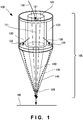
- FIG. 1 shows the arrangement of an optical processing nozzle 100 attached to the distal end of the head of an optical machining apparatus.
- the optical processing nozzle 100 includes a beam path 101 and a channel structure 102.
- the beam path 101 is arranged so that a beam 150 can pass through the beam path 101 toward a processing surface 160 in order to perform processing using the beam 150 guided from a light source (not shown).
- the light source can be, for example, a laser source, an LED, a halogen lamp, or a xenon lamp.
- the wavelength of a beam is, for example, 1,060 nm in the case of the laser source. However, the wavelength is not limited to this, and the beam 150 is arbitrary as long as it is absorbed by the processing surface 160.
- a fluid flowing through the channel structure 102 is, for example, a carrier gas carrying a powder.
- the powder is, for example, a particle such as a metal particle or a resin particle.
- the carrier gas is an inert gas and can be, for example, argon gas, nitrogen gas, or helium gas.
- the fluid is not limited to the carrier gas, and this structure may be used for a purge gas. In this case, since the concentration of the purge gas ejected to the processing surface can be homogenized, degradation of a shaped object by oxidation can be reduced. Note that the channel structure 102 is formed around the beam path 101 in order to eject a fluid 130 toward the processing surface 160.
- the channel structure 102 includes an inflow port 121 through which the fluid 130 flows, at least two passage holes 122 through which the fluid 130 flowing from the inflow port 121 passes, and a channel 123 that guides the fluid 130 from the inflow port 121 to the passage holes 122. Further, the channel structure 102 includes an ejection port 125 from which the fluid having passed through the passage holes 122 is ejected toward the processing surface 160.
- the two passage holes 122 are illustrated in Fig. 1 , the present invention is not limited to this.
- the passage hole 122 is a hole formed in a thin plate in Fig. 1 , the present invention is not limited to this and may employ a pipe-shaped passage hole.
- the passage holes 122 are arranged to be spatially symmetrical with respect to the inflow port 121.
- the passage holes 122 are rotated about an inflow axis that passes through the center of the inflow port 121 and extends in the inflow direction of a fluid in the inflow port 121, and one passage hole 122 coincides with the other passage hole 122 at a rotation angle of smaller than 360°, the passage holes 122 are considered to be spatially symmetrical with respect to the inflow port 121.
- the passage holes 122 are spatially symmetrical with respect to the inflow port 121, if channels from the inflow port 121 to the passage holes 122 have the same shape, fluid conductances become equal. At this time, a gas flowing from the inflow port 121 is equally divided in the passage holes 122, and flow rates in the passage holes 122 become equal.
- the ejection port 125 is arranged to be spatially symmetrical with respect to an optical axis 151 of the beam 150 coming out from the beam path 101.
- the ejection port 125 is rotated about the optical axis 151, and the ejection port 125 is coincident at a rotation angle of smaller than 360°, the ejection port 125 is considered to be spatially symmetrical with respect to the optical axis 151.
- one ejection port 125 having a rotationally symmetrical shape with respect to the optical axis 151 is illustrated in Fig. 1 , the present invention is not limited to this, and an optical processing nozzle including two or more ejection ports also falls within the technical scope.
- the ejection port 125 When the ejection port 125 is rotated about the optical axis 151, if the layout (position and shape of the entire ejection port) of the ejection port 125 is coincident at a rotation angle of smaller than 360°, the ejection port 125 is considered to be rotationally symmetrical with respect to the optical axis 151.
- the exits of the passage holes 122 may function as ejection ports. In this case, a downstream cone portion 140 becomes unnecessary.
- the optical processing nozzle 100 capable of homogeneously supplying a fluid to the processing surface with a very simple arrangement can be provided. Since flow rate nonuniformity of a carrier gas on the processing surface can be reduced, the processing accuracy can be improved.
- FIG. 2 is a view showing the internal arrangement of an optical processing nozzle 200.
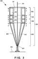
- the nozzle 200 includes a beam path 201 provided so that a beam can pass through the beam path 201 toward a processing surface 260 in order to perform processing using a beam guided from a light source, and a channel structure 202 that is arranged around the beam path 201 and is configured to eject a powder-containing carrier gas (to be simply referred to as a carrier gas hereinafter) 270 toward the processing surface 260.
- the channel structure 202 includes three channel layers 220, 230, and 240 and one ejection layer 250.
- the channel layer 220 includes an inflow port 221 through which the carrier gas 270 flows, two passage holes 222 through which the carrier gas 270 flowing from the inflow port 221 passes, and a channel 224 that guides the carrier gas 270 from the inflow port 221 to the passage holes 222.
- the channel layer 230 includes two inflow ports 231 through which the carrier gas 270 flows, four passage holes 232 through which the carrier gas 270 flowing from the inflow ports 231 passes, and a channel 234 that guides the carrier gas 270 from the inflow ports 231 to the passage holes 232.
- the channel layer 230 is continuous with the channel layer 220, and the respective downstream openings of the passage holes 222 directly function as the inflow ports 231.
- the channel layer 240 includes four inflow ports 241 through which the carrier gas 270 flows, eight passage holes 242 through which the carrier gas 270 flowing from the inflow ports 241 passes, and a channel 244 that guides the carrier gas 270 from the inflow ports 241 to the passage holes 242.
- the channel layer 240 is continuous with the channel layer 230, and the respective downstream openings of the passage holes 232 directly function as the inflow ports 241.
- the ejection layer 250 includes eight inflow ports 251 through which the carrier gas 270 flows, a channel 252 through which the carrier gas 270 flowing from the inflow ports 251 passes, and an ejection port 253 from which the carrier gas 270 is ejected outside the optical processing nozzle 200 from the channel 252.
- the ejection layer 250 is continuous with the channel layer 240, and the respective downstream openings of the passage holes 242 directly function as the inflow ports 251.
- the passage holes 222 are arranged to be spatially symmetrical with respect to the inflow port 221.
- the passage holes 232 are arranged to include at least one combination of a plurality of passage holes spatially symmetrical with respect to the inflow ports 231.
- the passage holes 242 are arranged to be spatially symmetrical with respect to the inflow ports 241.
- the passage holes 222 are arranged to be plane-symmetrical with respect to a plane including an optical axis 254 of the beam and passing through the center of the inflow port 221.
- any two of the passage holes 232 are arranged to be plane-symmetrical with respect to a plane including the optical axis 254 of the beam and passing through the center of the inflow port 231.
- any two of the passage holes 242 are arranged to be plane-symmetrical with respect to a plane including the optical axis 254 of the beam and passing through the center of the inflow port 241.
- the ejection port 253 is arranged to be spatially symmetrical with respect to the optical axis 254 of the beam incoming from the beam path 201.
- the ejection port 253 is an annular slit rotationally symmetrical with respect to the optical axis 254.
- the ejection port 253 may be at least two arcuate slits arranged side by side on a circle.
- the channel structure 202 is constituted by fitting, around the beam path 201, four ring-shaped disks each having openings at the center and the periphery. The number of openings formed in the ring-shaped disks increases downstream.
- the channel 224 of the uppermost-stream channel layer 220 is ensured to be larger than the channels of the remaining channel layers 230 and 240 in order to reduce the pressure loss.
- the channel 252 of the lowermost-stream ejection layer 250 has a shape tapered toward the downstream side by a cover 255. This structure can converge a powder from the ejection port 253 toward the processing surface 260. That is, the diameter of a powder spot formed on the processing surface 260 can be decreased, and high-definition shaping becomes possible.
- Fig. 3 is a longitudinal sectional view showing the optical processing nozzle 200 taken along a plane passing through the optical axis.
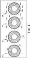
- Fig. 4 is a view showing an A-A section 401, a B-B section 402, a C-C section 403, and a D-D section 404 in Fig. 3 in comparison. Each section corresponds to the sectional view of each ring-shaped disk of the channel structure 202.
- the passage holes 222 (illustrated as passage holes 222a and 222b in Fig. 4 for convenience) are arranged to be spatially symmetrical with respect to the inflow port 221.
- a spatial gap from the inflow port 221 to the passage hole 222a and a spatial gap from the inflow port 221 to the passage hole 222b become equal, and the carrier gas flowing from the inflow port 221 equally flows into the passage holes 222a and 222b, and are discharged to the next layer.
- the positions of the inflow ports 231 on the section 402 are the same as those of the passage holes 222.
- the passage holes 232 (illustrated as passage holes 232a to 232d for convenience) are arranged to be spatially symmetrical (for example, arranged at an equal distance) with respect to the inflow ports 231.
- the positions of the inflow ports 241 on the section 403 are the same as those of the passage holes 232.
- the passage holes 242 (illustrated as passage holes 242a to 242h for convenience) are arranged to be spatially symmetrical with respect to the inflow ports 241.
- a fluid passing through the passage hole 222a is equally guided to the passage holes 232a and 232b.
- the fluid passing through the passage hole 222b is equally guided to the passage holes 232c and 232d.
- the fluid passing through the passage hole 232a is equally guided to the passage holes 242a and 242b
- the fluid passing through the passage hole 232b is equally guided to the passage holes 242c and 242d.
- the fluid passing through the passage hole 232c is equally guided to the passage holes 242e and 242f
- the fluid passing through the passage hole 232d is equally guided to the passage holes 242g and 242h.
- This embodiment has explained the channel structure 202 including the three channel layers 220 to 240 having the inflow ports and the passage holes.
- the present invention is not limited to this, and the number of channel layers may be one, two, or four or more.
- the Ath channel layer includes the Ath inflow port through which a fluid flows.
- the Ath channel layer also includes at least two Ath passage holes through which the carrier gas flowing from the Ath inflow port passes, and the Ath channel that guides the fluid from the Ath inflow port to the Ath passage holes.
- the Bth channel layer includes the Bth inflow port through which the fluid flows from the Ath passage holes.
- the Bth channel layer also includes at least two Bth passage holes through which the fluid flowing from the Bth inflow port passes, and the Bth channel that guides the fluid from the Bth inflow port to the Bth passage holes.
- the Ath passage holes are arranged to be spatially symmetrical with respect to the inflow direction of the Ath inflow port.
- the Bth passage holes are arranged to be spatially symmetrical with respect to the inflow direction of the Bth inflow port.
- the number of passage holes of the final layer is 2 M .
- the distance (gap) between adjacent passage holes communicating with the ejection port suffices to be minimum. That is, the gap is set to be 0. This is because, when the gap is 0, the powder around the optical axis is equally distributed in all directions, and most isotropically distributed.
- a carrier gas flowing from the inflow port 221 can be equally divided inside the nozzle 200, and the isotropy of carriage gas ejection to the processing surfaced can be finally improved. Accordingly, a homogeneous powder spot without nonuniformity can be implemented.
- the processing accuracy of overlay welding or the like is improved by condensing a beam on the processing surface and forming a powder spot at a molten portion. Since the powder need not be equally branched at a supply portion (inlet portion) for supplying powder to the nozzle, the inlet portion can be simplified. As a result, the limitation of the movable range of the overall machining apparatus is reduced, and powder deposition at the inlet portion can be suppressed.
- FIG. 5 is a partial perspective view for explaining the arrangement of the optical processing nozzle 500 according to this embodiment.
- the optical processing nozzle 500 according to the second embodiment is different from the optical processing nozzle according to the first embodiment in that it does not include a cover 255.
- the remaining arrangement and operation are the same as those in the first embodiment, so the same reference numerals denote the same arrangement and operation and a detailed description thereof will not be repeated.
- the downstream openings of passage holes 242 directly serve as ejection ports 553. That is, the ejection ports 553 are constituted by a plurality of openings of the same shape. Even in this case, the ejection ports 553 are arranged to be spatially symmetrical with respect to an optical axis 254, as a matter of course.
- Figs. 6 and 7 show a fluid simulation result according to this embodiment.
- the cone shape of the distal end in Fig. 5 is not illustrated in the analysis model of this simulation.
- the fluid is, for example, a powder flow prepared by mixing SUS having a particle diameter of 30 ⁇ m in nitrogen gas serving as a carrier gas.
- Fig. 6 is a view showing the flow velocity distribution of the powder flow by grayscale concentration contour lines.
- the powder flow is equally branched by the respective layers, and is distributed to be rotationally symmetrical (isotopically) with respect to the optical axis 254.
- Fig. 7 shows a flow velocity distribution on a section passing through the ejection ports 553.
- Fig. 6 is a powder flow prepared by mixing SUS having a particle diameter of 30 ⁇ m in nitrogen gas serving as a carrier gas.
- Fig. 6 is a view showing the flow velocity distribution of the powder flow by grayscale concentration contour lines.
- the powder flow is equally branched by the respective layers, and is distributed
- the maximum concentration is almost equal between the ejection ports 553, and the maximum flow velocity is equal between the ejection ports 553.
- the flow rate can be calculated by integrating the flow velocity by the opening area of each ejection port. As a result, the flow rates in the respective ejection ports become almost equal, the variation becomes 5.2% or less, and the variation of the flow velocity becomes satisfactorily small.
- Experimental findings reveal that, if the variation is equal to or smaller than 10%, no anisotropy is observed in the property of a shaped object. In this example, the variation is about 5.2%, which is sufficiently small.
- This simulation result can be referred to even for the arrangement described in the first embodiment in which the cover 255 is arranged. That is, even the arrangement described in the first embodiment can implement isotropic powder ejection.
- the second embodiment can implement a large powder spot diameter and enables high-speed shaping.
- the cover 255 By arranging the cover 255 to be easily detachable in the arrangement according to the first embodiment, the arrangement according to the first embodiment and the arrangement according to the second embodiment can be freely switched. That is, one nozzle can be used for two types of application purposes, that is, high-definition shaping and high-speed shaping.
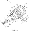
- FIG. 8 is a partial perspective view for explaining the arrangement of the optical processing nozzle 800 according to this embodiment.
- the optical processing nozzle 800 according to the third embodiment is different from the optical processing nozzle according to the second embodiment in that it includes eight pipe-shaped passage holes 842 extending downstream from a channel layer 240, and the opening ends of the passage holes 842 serve as ejection ports 853.
- the remaining arrangement and operation are the same as those in the second embodiment, so the same reference numerals denote the same arrangement and operation and a detailed description thereof will not be repeated.
- the ejection direction can be changed by changing the angles of the passage holes 842.
- the shape of a powder spot can therefore be controlled. If the passage holes 842 are made long, this gives an effect capable of reducing the variation of ejection and decreasing the powder convergent spot diameter.
- FIG. 9 is a partial perspective view for explaining the arrangement of the optical processing nozzle 900 according to this embodiment.
- the optical processing nozzle 900 according to the fourth embodiment is different from the optical processing nozzle according to the first embodiment in that it includes pipe-shaped passage holes 942 slightly extending downstream from a channel layer 240.
- the remaining arrangement and operation are the same as those in the first embodiment, so the same reference numerals denote the same arrangement and operation and a detailed description thereof will not be repeated.
- a carrier gas is sprayed to the side surface of a cone shape formed in a cover 255, and is distributed.
- the carrier gas is satisfactorily equally distributed and ejected, improving the homogeneity.
- the cone shape is constituted by a distribution portion at which a carrier gas is distributed, and a portion tapered toward the distal end.
- the distribution portion is tapered toward an upstream portion (opposite to the optical axis direction), but is not limited to this.
- the distribution portion may be a cylinder.
- Passage holes 942 are constituted so that they can be adjusted to an orientation in which a carrier gas is sprayed toward the distribution portion.
- the optical machining apparatus 1000 is an apparatus that includes one of the optical processing nozzles 200, 500, 800, and 900 explained in the above-described embodiments, and generates a three-dimensional shaped object (or overlay welding).
- the optical machining apparatus 1000 including an optical processing nozzle 200 will be explained as an example.
- the optical machining apparatus 1000 includes a light source 1001, a light transmitting portion 1002, a coolant supply device 1003, a coolant supply portion 1004, a stage 1005, a fluid storage device 1006, a fluid supply portion 1030, a gas supply device 1008, a gas supply portion 1040, and an optical processing head 1020.
- the optical processing nozzle 200 is attached as part of the optical processing head 1020 to the distal end of the optical processing head 1020.
- the light source 1001 can be, for example, a laser source, an LED, a halogen lamp, or a xenon lamp.
- the wavelength of a beam is, for example, 1,060 nm in the case of the laser source. However, the wavelength is not limited to this, and light is arbitrary as long as it is absorbed by a processing surface 260.
- the light transmitting portion 1002 is, for example, an optical fiber having a core diameter of ⁇ 0.01 to 1 mm, and guides light generated by the light source 1001 to the optical processing head 1020.
- the core diameter of the light transmitting portion 1002 serves as the diameter of an incident end 1012.
- the coolant supply device 1003 stores, for example, water as a coolant, and supplies the coolant by a pump to the coolant supply portion 1004.
- the coolant supply portion 1004 is a resin or metal hose having an inner diameter of ⁇ 2 to 6.
- the coolant is supplied into the optical processing head 1020, circulated inside it, and returned to the coolant supply device 1003, thereby suppressing the temperature rise of the optical processing head 1020.
- the coolant supply amount is, for example, 1 to 10 L/min.
- the stage 1005 is, for example, an X stage, an X-Y stage, or an X-Y-Z stage, and the respective axes (X, Y, and Z) can be driven.
- the fluid storage device 1006 supplies a material-containing carrier gas to the optical processing nozzle 200 via a fluid supply portion 1007.
- the material is, for example, a particle such as a metal particle or a resin particle.
- the carrier gas is an inert gas and can be, for example, argon gas, nitrogen gas, or helium gas.
- the fluid supply portion 1030 is, for example, a resin or metal hose, and guides, to the nozzle 200, a powder flow prepared by mixing a material in a carrier gas. However, when the material is a wire, no carrier gas is necessary.
- the gas supply device 1008 supplies a purge gas to the optical processing head 1020 through the gas supply portion 1040.
- the purge gas is, for example, nitrogen, argon, or helium. However, the purge gas is not limited to this and may also be another gas as long as the purge gas is an inert gas.
- the purge gas supplied to the optical processing head 1020 is ejected from the nozzle 200 along the above-described beam.
- the optical processing head 1020 includes at least the optical processing nozzle 200 explained in the above-described embodiment, and a condensing optical system device 1021 that condenses light emitted by the light source 1001 and ejects it toward the processing surface 260.
- the optical machining apparatus 1000 may include an orientation control mechanism and position control mechanism that control the orientation and position of the optical processing head 1020.
- a shaped object 1010 is created on the stage 1005.
- Light emitted by the optical processing head 1020 is condensed to the processing surface 260 on the shaped object 1010.
- the temperature of the processing surface 260 is raised by the condensed light, and the processing surface 260 is melted, partially forming a molten pool.
- the material is ejected from the nozzle 200 to the molten pool of the processing surface 260.
- the material is melted into the molten pool. After that, the molten pool is cooled and hardened to deposit the material on the processing surface 260, implementing three-dimensional shaping.
- the purge gas is ejected from the nozzle 200 to the processing surface 260.
- the peripheral environment of the molten pool is purged with the purge gas.
- an oxygen-free inert gas as the purge gas, oxidization of the processing surface 260 can be prevented.
- the optical processing head 1020 is cooled by the coolant supplied from the coolant supply device 1003 through the coolant supply portion 1004, suppressing the temperature rise during processing.
- this apparatus can implement overlay welding or three-dimensional shaping.
Landscapes
- Engineering & Computer Science (AREA)
- Physics & Mathematics (AREA)
- Optics & Photonics (AREA)
- Chemical & Material Sciences (AREA)
- Materials Engineering (AREA)
- Manufacturing & Machinery (AREA)
- Mechanical Engineering (AREA)
- Plasma & Fusion (AREA)
- Health & Medical Sciences (AREA)
- Toxicology (AREA)
- Laser Beam Processing (AREA)
Description
- The present invention relates to an optical processing nozzle and an optical machining apparatus.
- In the above technical field, patent literature 1 discloses a laser processing head in which a branched carrier gas flows from a plurality of inflow paths 9 and 10 into a nozzle 4.
- Patent literature 1:
US Patent Application Publication No. 2005/0109745A1 Prior art can be found e.g. in documentUS 2012/0195334 A1 disclosing a laser material processing tool, in documentUS 5,556,560 disclosing a welding assembly for feeding powered filler material into a torch, in documentDE 20 2008 002 271 U1 disclosing a device for supplying a substance for welding, sintering or blending a workpiece, in documentUS 2001/0008230 A1 disclosing an energy-beam-driven rapid fabrication system, and in documentDE 10 2004 034 777 A1 disclosing a nozzle for laser welding. - In the technique described in this literature, however, a gas is branched outside the nozzle and supplied through a plurality of supply channels. The flow rates of respective gas flows readily vary until the branched gas flows reach the nozzle. That is, the optical processing nozzle cannot homogeneously supply a fluid to a processing surface conventionally.
- The present invention enables to provide a technique of solving the above-described problem.
- One aspect of the present invention provides an optical processing nozzle according to claim 1.
- Another aspect of the present invention provides an optical processing head according to the respective claim.
- Still other aspect of the present invention provides an optical machining apparatus according to the respective claim.
- The present invention can provide an optical processing nozzle capable of homogeneously supplying a fluid to a processing surface.
-
-
Fig. 1 is a view showing the arrangement of an optical processing nozzle according to a first example useful for understanding the present invention; -
Fig. 2 is a view showing the arrangement of an optical processing nozzle according to the first embodiment of the present invention; -
Fig. 3 is a sectional view showing the arrangement of the optical processing nozzle according to the first embodiment of the present invention; -
Fig. 4 is a sectional view showing the arrangement of the optical processing nozzle according to the first embodiment of the present invention; -
Fig. 5 is a view showing the arrangement of an optical processing nozzle according to the second embodiment of the present invention; -
Fig. 6 is a view for explaining an effect obtained by the optical processing nozzle according to the second embodiment of the present invention; -
Fig. 7 is a view for explaining an effect obtained by the optical processing nozzle according to the second embodiment of the present invention; -
Fig. 8 is a view showing the arrangement of an optical processing nozzle according to the third embodiment of the present invention; -
Fig. 9 is a view showing the arrangement of an optical processing nozzle according to the fourth embodiment of the present invention; and -
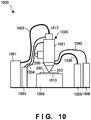
Fig. 10 is a view showing the overall arrangement of an optical machining apparatus according to the fifth embodiment of the present invention. - A preferred embodiment(s) of the present invention will now be described in detail with reference to the drawings. It should be noted that the relative arrangement of the components, the numerical expressions and numerical values set forth in these embodiments do not limit the scope of the present invention unless it is specifically stated otherwise.
- An optical processing nozzle according to the first example useful for understanding the present invention will be described with reference to
Fig. 1. Fig. 1 shows the arrangement of anoptical processing nozzle 100 attached to the distal end of the head of an optical machining apparatus. Theoptical processing nozzle 100 includes abeam path 101 and achannel structure 102. - The
beam path 101 is arranged so that abeam 150 can pass through thebeam path 101 toward aprocessing surface 160 in order to perform processing using thebeam 150 guided from a light source (not shown). The light source can be, for example, a laser source, an LED, a halogen lamp, or a xenon lamp. The wavelength of a beam is, for example, 1,060 nm in the case of the laser source. However, the wavelength is not limited to this, and thebeam 150 is arbitrary as long as it is absorbed by theprocessing surface 160. - A fluid flowing through the
channel structure 102 is, for example, a carrier gas carrying a powder. The powder is, for example, a particle such as a metal particle or a resin particle. The carrier gas is an inert gas and can be, for example, argon gas, nitrogen gas, or helium gas. Further, the fluid is not limited to the carrier gas, and this structure may be used for a purge gas. In this case, since the concentration of the purge gas ejected to the processing surface can be homogenized, degradation of a shaped object by oxidation can be reduced. Note that thechannel structure 102 is formed around thebeam path 101 in order to eject afluid 130 toward theprocessing surface 160. - The
channel structure 102 includes aninflow port 121 through which thefluid 130 flows, at least twopassage holes 122 through which thefluid 130 flowing from theinflow port 121 passes, and achannel 123 that guides thefluid 130 from theinflow port 121 to thepassage holes 122. Further, thechannel structure 102 includes anejection port 125 from which the fluid having passed through thepassage holes 122 is ejected toward theprocessing surface 160. Although the twopassage holes 122 are illustrated inFig. 1 , the present invention is not limited to this. Although thepassage hole 122 is a hole formed in a thin plate inFig. 1 , the present invention is not limited to this and may employ a pipe-shaped passage hole. - The
passage holes 122 are arranged to be spatially symmetrical with respect to theinflow port 121. When thepassage holes 122 are rotated about an inflow axis that passes through the center of theinflow port 121 and extends in the inflow direction of a fluid in theinflow port 121, and onepassage hole 122 coincides with theother passage hole 122 at a rotation angle of smaller than 360°, thepassage holes 122 are considered to be spatially symmetrical with respect to theinflow port 121. When thepassage holes 122 are spatially symmetrical with respect to theinflow port 121, if channels from theinflow port 121 to thepassage holes 122 have the same shape, fluid conductances become equal. At this time, a gas flowing from theinflow port 121 is equally divided in thepassage holes 122, and flow rates in thepassage holes 122 become equal. - The
ejection port 125 is arranged to be spatially symmetrical with respect to anoptical axis 151 of thebeam 150 coming out from thebeam path 101. When theejection port 125 is rotated about theoptical axis 151, and theejection port 125 is coincident at a rotation angle of smaller than 360°, theejection port 125 is considered to be spatially symmetrical with respect to theoptical axis 151. Although oneejection port 125 having a rotationally symmetrical shape with respect to theoptical axis 151 is illustrated inFig. 1 , the present invention is not limited to this, and an optical processing nozzle including two or more ejection ports also falls within the technical scope. When theejection port 125 is rotated about theoptical axis 151, if the layout (position and shape of the entire ejection port) of theejection port 125 is coincident at a rotation angle of smaller than 360°, theejection port 125 is considered to be rotationally symmetrical with respect to theoptical axis 151. In particular, the exits of thepassage holes 122 may function as ejection ports. In this case, adownstream cone portion 140 becomes unnecessary. - According to the above-described arrangement, the
optical processing nozzle 100 capable of homogeneously supplying a fluid to the processing surface with a very simple arrangement can be provided. Since flow rate nonuniformity of a carrier gas on the processing surface can be reduced, the processing accuracy can be improved. - An optical processing nozzle according to the first embodiment of the present invention will be described with reference to
Figs. 2 and3 .Fig. 2 is a view showing the internal arrangement of anoptical processing nozzle 200. - The
nozzle 200 includes abeam path 201 provided so that a beam can pass through thebeam path 201 toward aprocessing surface 260 in order to perform processing using a beam guided from a light source, and achannel structure 202 that is arranged around thebeam path 201 and is configured to eject a powder-containing carrier gas (to be simply referred to as a carrier gas hereinafter) 270 toward theprocessing surface 260. Thechannel structure 202 includes threechannel layers ejection layer 250. - The
channel layer 220 includes aninflow port 221 through which thecarrier gas 270 flows, twopassage holes 222 through which thecarrier gas 270 flowing from theinflow port 221 passes, and achannel 224 that guides thecarrier gas 270 from theinflow port 221 to the passage holes 222. - The
channel layer 230 includes twoinflow ports 231 through which thecarrier gas 270 flows, fourpassage holes 232 through which thecarrier gas 270 flowing from theinflow ports 231 passes, and achannel 234 that guides thecarrier gas 270 from theinflow ports 231 to the passage holes 232. Thechannel layer 230 is continuous with thechannel layer 220, and the respective downstream openings of the passage holes 222 directly function as theinflow ports 231. - The
channel layer 240 includes fourinflow ports 241 through which thecarrier gas 270 flows, eight passage holes 242 through which thecarrier gas 270 flowing from theinflow ports 241 passes, and achannel 244 that guides thecarrier gas 270 from theinflow ports 241 to the passage holes 242. Thechannel layer 240 is continuous with thechannel layer 230, and the respective downstream openings of the passage holes 232 directly function as theinflow ports 241. - The
ejection layer 250 includes eightinflow ports 251 through which thecarrier gas 270 flows, achannel 252 through which thecarrier gas 270 flowing from theinflow ports 251 passes, and anejection port 253 from which thecarrier gas 270 is ejected outside theoptical processing nozzle 200 from thechannel 252. Theejection layer 250 is continuous with thechannel layer 240, and the respective downstream openings of the passage holes 242 directly function as theinflow ports 251. - The passage holes 222 are arranged to be spatially symmetrical with respect to the
inflow port 221. The passage holes 232 are arranged to include at least one combination of a plurality of passage holes spatially symmetrical with respect to theinflow ports 231. The passage holes 242 are arranged to be spatially symmetrical with respect to theinflow ports 241. The passage holes 222 are arranged to be plane-symmetrical with respect to a plane including anoptical axis 254 of the beam and passing through the center of theinflow port 221. Similarly, any two of the passage holes 232 are arranged to be plane-symmetrical with respect to a plane including theoptical axis 254 of the beam and passing through the center of theinflow port 231. Also, any two of the passage holes 242 are arranged to be plane-symmetrical with respect to a plane including theoptical axis 254 of the beam and passing through the center of theinflow port 241. - The
ejection port 253 is arranged to be spatially symmetrical with respect to theoptical axis 254 of the beam incoming from thebeam path 201. In particular, theejection port 253 is an annular slit rotationally symmetrical with respect to theoptical axis 254. Theejection port 253 may be at least two arcuate slits arranged side by side on a circle. In other words, thechannel structure 202 is constituted by fitting, around thebeam path 201, four ring-shaped disks each having openings at the center and the periphery. The number of openings formed in the ring-shaped disks increases downstream. - As shown in
Fig. 2 , thechannel 224 of the uppermost-stream channel layer 220 is ensured to be larger than the channels of the remaining channel layers 230 and 240 in order to reduce the pressure loss. Thechannel 252 of the lowermost-stream ejection layer 250 has a shape tapered toward the downstream side by acover 255. This structure can converge a powder from theejection port 253 toward theprocessing surface 260. That is, the diameter of a powder spot formed on theprocessing surface 260 can be decreased, and high-definition shaping becomes possible. -
Fig. 3 is a longitudinal sectional view showing theoptical processing nozzle 200 taken along a plane passing through the optical axis.Fig. 4 is a view showing anA-A section 401, aB-B section 402, aC-C section 403, and aD-D section 404 inFig. 3 in comparison. Each section corresponds to the sectional view of each ring-shaped disk of thechannel structure 202. As shown inFig. 4 , the passage holes 222 (illustrated aspassage holes Fig. 4 for convenience) are arranged to be spatially symmetrical with respect to theinflow port 221. Hence, a spatial gap from theinflow port 221 to thepassage hole 222a and a spatial gap from theinflow port 221 to thepassage hole 222b become equal, and the carrier gas flowing from theinflow port 221 equally flows into the passage holes 222a and 222b, and are discharged to the next layer. - In this embodiment, the positions of the
inflow ports 231 on thesection 402 are the same as those of the passage holes 222. The passage holes 232 (illustrated aspassage holes 232a to 232d for convenience) are arranged to be spatially symmetrical (for example, arranged at an equal distance) with respect to theinflow ports 231. Also, the positions of theinflow ports 241 on thesection 403 are the same as those of the passage holes 232. The passage holes 242 (illustrated aspassage holes 242a to 242h for convenience) are arranged to be spatially symmetrical with respect to theinflow ports 241. - Referring to the positions of the passage holes 222a and 222b, a fluid passing through the
passage hole 222a is equally guided to the passage holes 232a and 232b. Similarly, the fluid passing through thepassage hole 222b is equally guided to the passage holes 232c and 232d. In the same way, the fluid passing through thepassage hole 232a is equally guided to the passage holes 242a and 242b, and the fluid passing through thepassage hole 232b is equally guided to the passage holes 242c and 242d. Similarly, the fluid passing through thepassage hole 232c is equally guided to the passage holes 242e and 242f, and the fluid passing through thepassage hole 232d is equally guided to the passage holes 242g and 242h. - This embodiment has explained the
channel structure 202 including the threechannel layers 220 to 240 having the inflow ports and the passage holes. However, the present invention is not limited to this, and the number of channel layers may be one, two, or four or more. - In this case, when an upstream side (side in a direction opposite to the beam direction) is defined as the Ath channel layer and a downstream side (side in the same direction as the beam direction) is defined as the Bth channel layer in all combinations each of two successive channel layers, it is preferable that the following relationship is established. That is, the Ath channel layer includes the Ath inflow port through which a fluid flows. The Ath channel layer also includes at least two Ath passage holes through which the carrier gas flowing from the Ath inflow port passes, and the Ath channel that guides the fluid from the Ath inflow port to the Ath passage holes. The Bth channel layer includes the Bth inflow port through which the fluid flows from the Ath passage holes. The Bth channel layer also includes at least two Bth passage holes through which the fluid flowing from the Bth inflow port passes, and the Bth channel that guides the fluid from the Bth inflow port to the Bth passage holes. The Ath passage holes are arranged to be spatially symmetrical with respect to the inflow direction of the Ath inflow port. The Bth passage holes are arranged to be spatially symmetrical with respect to the inflow direction of the Bth inflow port.
- When two passage holes are associated with each inflow port in all channel layers, and M represents the total number of layers, the number of passage holes of the final layer is 2M. At this time, to maximize the isotropy of a powder ejected from the ejection port by the smallest number of layers, the distance (gap) between adjacent passage holes communicating with the ejection port suffices to be minimum. That is, the gap is set to be 0. This is because, when the gap is 0, the powder around the optical axis is equally distributed in all directions, and most isotropically distributed. At this time, letting R be the average distance of the passage hole communicating with the ejection port from the
optical axis 254, and D be the diameter of the passage hole communicating with the ejection port,
- With this arrangement, a carrier gas flowing from the
inflow port 221 can be equally divided inside thenozzle 200, and the isotropy of carriage gas ejection to the processing surfaced can be finally improved. Accordingly, a homogeneous powder spot without nonuniformity can be implemented. At this time, the processing accuracy of overlay welding or the like is improved by condensing a beam on the processing surface and forming a powder spot at a molten portion. Since the powder need not be equally branched at a supply portion (inlet portion) for supplying powder to the nozzle, the inlet portion can be simplified. As a result, the limitation of the movable range of the overall machining apparatus is reduced, and powder deposition at the inlet portion can be suppressed. - An
optical processing nozzle 500 according to the second embodiment of the present invention will be described with reference toFig. 5. Fig. 5 is a partial perspective view for explaining the arrangement of theoptical processing nozzle 500 according to this embodiment. Theoptical processing nozzle 500 according to the second embodiment is different from the optical processing nozzle according to the first embodiment in that it does not include acover 255. The remaining arrangement and operation are the same as those in the first embodiment, so the same reference numerals denote the same arrangement and operation and a detailed description thereof will not be repeated. - In this arrangement, the downstream openings of passage holes 242 directly serve as
ejection ports 553. That is, theejection ports 553 are constituted by a plurality of openings of the same shape. Even in this case, theejection ports 553 are arranged to be spatially symmetrical with respect to anoptical axis 254, as a matter of course. -
Figs. 6 and7 show a fluid simulation result according to this embodiment. However, the cone shape of the distal end inFig. 5 is not illustrated in the analysis model of this simulation. In the simulation, the fluid is, for example, a powder flow prepared by mixing SUS having a particle diameter of 30 µm in nitrogen gas serving as a carrier gas.Fig. 6 is a view showing the flow velocity distribution of the powder flow by grayscale concentration contour lines. As is apparent fromFig. 6 , the powder flow is equally branched by the respective layers, and is distributed to be rotationally symmetrical (isotopically) with respect to theoptical axis 254.Fig. 7 shows a flow velocity distribution on a section passing through theejection ports 553. As is apparent fromFig. 7 , the maximum concentration is almost equal between theejection ports 553, and the maximum flow velocity is equal between theejection ports 553. The flow rate can be calculated by integrating the flow velocity by the opening area of each ejection port. As a result, the flow rates in the respective ejection ports become almost equal, the variation becomes 5.2% or less, and the variation of the flow velocity becomes satisfactorily small. Experimental findings reveal that, if the variation is equal to or smaller than 10%, no anisotropy is observed in the property of a shaped object. In this example, the variation is about 5.2%, which is sufficiently small. - This simulation result can be referred to even for the arrangement described in the first embodiment in which the
cover 255 is arranged. That is, even the arrangement described in the first embodiment can implement isotropic powder ejection. - Since no fluid is compressed at the time of ejection in the second embodiment, the pressure loss is small. That is, the second embodiment can implement a large powder spot diameter and enables high-speed shaping. By arranging the
cover 255 to be easily detachable in the arrangement according to the first embodiment, the arrangement according to the first embodiment and the arrangement according to the second embodiment can be freely switched. That is, one nozzle can be used for two types of application purposes, that is, high-definition shaping and high-speed shaping. - An
optical processing nozzle 800 according to the third embodiment of the present invention will be explained with reference toFig. 8. Fig. 8 is a partial perspective view for explaining the arrangement of theoptical processing nozzle 800 according to this embodiment. Theoptical processing nozzle 800 according to the third embodiment is different from the optical processing nozzle according to the second embodiment in that it includes eight pipe-shaped passage holes 842 extending downstream from achannel layer 240, and the opening ends of the passage holes 842 serve asejection ports 853. The remaining arrangement and operation are the same as those in the second embodiment, so the same reference numerals denote the same arrangement and operation and a detailed description thereof will not be repeated. - According to this embodiment, the ejection direction can be changed by changing the angles of the passage holes 842. The shape of a powder spot can therefore be controlled. If the passage holes 842 are made long, this gives an effect capable of reducing the variation of ejection and decreasing the powder convergent spot diameter. By orienting the ejection direction to a direction along a cone shape arranged at the distal end of the nozzle, a fluid can flow along the cone shape. That is, the flow of the fluid becomes a laminar flow along the wall surface of the cone shape. This can further enhance the powder convergence.
- An
optical processing nozzle 900 according to the fourth embodiment of the present invention will be explained with reference toFig. 9. Fig. 9 is a partial perspective view for explaining the arrangement of theoptical processing nozzle 900 according to this embodiment. Theoptical processing nozzle 900 according to the fourth embodiment is different from the optical processing nozzle according to the first embodiment in that it includes pipe-shaped passage holes 942 slightly extending downstream from achannel layer 240. The remaining arrangement and operation are the same as those in the first embodiment, so the same reference numerals denote the same arrangement and operation and a detailed description thereof will not be repeated. - According to this embodiment, a carrier gas is sprayed to the side surface of a cone shape formed in a
cover 255, and is distributed. The carrier gas is satisfactorily equally distributed and ejected, improving the homogeneity. - The cone shape is constituted by a distribution portion at which a carrier gas is distributed, and a portion tapered toward the distal end. The distribution portion is tapered toward an upstream portion (opposite to the optical axis direction), but is not limited to this. For example, the distribution portion may be a cylinder.
- Passage holes 942 are constituted so that they can be adjusted to an orientation in which a carrier gas is sprayed toward the distribution portion.
- An
optical machining apparatus 1000 according to the fifth embodiment of the present invention will be described with reference toFig. 10 . Theoptical machining apparatus 1000 is an apparatus that includes one of theoptical processing nozzles optical machining apparatus 1000 including anoptical processing nozzle 200 will be explained as an example. - The
optical machining apparatus 1000 includes alight source 1001, alight transmitting portion 1002, acoolant supply device 1003, acoolant supply portion 1004, astage 1005, a fluid storage device 1006, afluid supply portion 1030, a gas supply device 1008, agas supply portion 1040, and anoptical processing head 1020. Theoptical processing nozzle 200 is attached as part of theoptical processing head 1020 to the distal end of theoptical processing head 1020. - The
light source 1001 can be, for example, a laser source, an LED, a halogen lamp, or a xenon lamp. The wavelength of a beam is, for example, 1,060 nm in the case of the laser source. However, the wavelength is not limited to this, and light is arbitrary as long as it is absorbed by aprocessing surface 260. - The
light transmitting portion 1002 is, for example, an optical fiber having a core diameter of φ0.01 to 1 mm, and guides light generated by thelight source 1001 to theoptical processing head 1020. The core diameter of thelight transmitting portion 1002 serves as the diameter of anincident end 1012. Thecoolant supply device 1003 stores, for example, water as a coolant, and supplies the coolant by a pump to thecoolant supply portion 1004. - The
coolant supply portion 1004 is a resin or metal hose having an inner diameter of φ2 to 6. The coolant is supplied into theoptical processing head 1020, circulated inside it, and returned to thecoolant supply device 1003, thereby suppressing the temperature rise of theoptical processing head 1020. The coolant supply amount is, for example, 1 to 10 L/min. - The
stage 1005 is, for example, an X stage, an X-Y stage, or an X-Y-Z stage, and the respective axes (X, Y, and Z) can be driven. The fluid storage device 1006 supplies a material-containing carrier gas to theoptical processing nozzle 200 via a fluid supply portion 1007. The material is, for example, a particle such as a metal particle or a resin particle. The carrier gas is an inert gas and can be, for example, argon gas, nitrogen gas, or helium gas. - The
fluid supply portion 1030 is, for example, a resin or metal hose, and guides, to thenozzle 200, a powder flow prepared by mixing a material in a carrier gas. However, when the material is a wire, no carrier gas is necessary. - The gas supply device 1008 supplies a purge gas to the
optical processing head 1020 through thegas supply portion 1040. The purge gas is, for example, nitrogen, argon, or helium. However, the purge gas is not limited to this and may also be another gas as long as the purge gas is an inert gas. The purge gas supplied to theoptical processing head 1020 is ejected from thenozzle 200 along the above-described beam. Theoptical processing head 1020 includes at least theoptical processing nozzle 200 explained in the above-described embodiment, and a condensingoptical system device 1021 that condenses light emitted by thelight source 1001 and ejects it toward theprocessing surface 260. - Although not shown, the
optical machining apparatus 1000 may include an orientation control mechanism and position control mechanism that control the orientation and position of theoptical processing head 1020. - Next, the operation of the
optical machining apparatus 1000 will be explained. A shapedobject 1010 is created on thestage 1005. Light emitted by theoptical processing head 1020 is condensed to theprocessing surface 260 on the shapedobject 1010. The temperature of theprocessing surface 260 is raised by the condensed light, and theprocessing surface 260 is melted, partially forming a molten pool. - The material is ejected from the
nozzle 200 to the molten pool of theprocessing surface 260. The material is melted into the molten pool. After that, the molten pool is cooled and hardened to deposit the material on theprocessing surface 260, implementing three-dimensional shaping. - The purge gas is ejected from the
nozzle 200 to theprocessing surface 260. Thus, the peripheral environment of the molten pool is purged with the purge gas. By selecting an oxygen-free inert gas as the purge gas, oxidization of theprocessing surface 260 can be prevented. - The
optical processing head 1020 is cooled by the coolant supplied from thecoolant supply device 1003 through thecoolant supply portion 1004, suppressing the temperature rise during processing. - By scanning the
optical processing head 1020 along theprocessing surface 260 at the same time as the above-described series of operations, desired shaping can be performed while depositing the material. That is, this apparatus can implement overlay welding or three-dimensional shaping. - The present invention has been described above with reference to the embodiments. However, the present invention is not limited to those embodiments. Various changes understandable by those skilled in the art within the scope of the present invention as defined by the claims can be made.
Claims (11)
- An optical processing nozzle (200) comprising:a beam path (201) that is arranged to allow a beam emitted by a light source to pass through the beam path toward a processing surface (260); anda channel structure (202) that is arranged around the beam path and is configured to eject a fluid toward the processing surface,wherein the channel structure includes:a first channel layer (220) including a first inflow port (221) through which the fluid flows, at least two first passage holes (222) through which the fluid flowing from the first inflow port passes, and a first channel (224) that guides the fluid from the first inflow port to the first passage holes; anda second channel layer (230) including at least two second inflow ports (231) through which the fluid flows from the first passage holes, at least four second passage holes (232) through which the fluid flowing from the at least second inflow port passes, and a second channel (234) that guides the fluid from the at least two second inflow ports to the at least four second passage holes,an ejection port (253) from which the fluid having passed through the at least four second passage holes (232) is ejected toward the processing surface,the at least two first passage holes (222) are arranged such that, when the at least two first passage holes (222) are rotated about an inflow axis that passes through the center of the first inflow port (221) and extends in the inflow direction of the fluid in the first inflow port (221), one of the first passage holes (222) coincides with the other of the first passage holes (222) at a rotation angle of smaller than 360°,for each of the at least two second inflow ports (231) at least one respective combination of the at least four second passage holes (232) is arranged such that, when the second passage holes (232) of the respective combination are rotated about a respective inflow axis that passes through the center of the respective second inflow port (231) and extends in the inflow direction of the fluid in the respective second inflow port, one of the second passage holes (232) of the respective combination coincides with another of the second passage holes (232) of the respective combination at a rotation angle of smaller than 360°, andthe ejection port (253) is arranged such that, when the ejection port is rotated about the optical axis, the ejection port is coincident at a rotation angle of smaller than 360°.
- The optical processing nozzle according to claim 1, wherein the at least two first passage holes (222) are arranged to be plane-symmetrical with respect to a plane including the optical axis of the beam and passing through a center of the first inflow port (221).
- The optical processing nozzle according to claim 1 or 2, wherein the ejection port (253) includes at least two ejection ports that are identical in shape, and are arranged at positions rotationally symmetrical with respect to the optical axis.
- The optical processing head according to claim 1 or 2, wherein the ejection port (253) is an annular or arcuate slit.
- The optical processing nozzle according to any one of claims 1 to 4, wherein the at least two first passage holes (222) include at least one pair of passage holes arranged at an equal distance from the inflow port.
- The optical processing nozzle according to any one of claims 1 to 5, wherein said channel structure further includes at least:a third channel layer (240) including at least four third inflow ports (241) through which the fluid flows from the second passage holes, at least eight third passage holes (242) through which the fluid flowing from the third inflow port (241) passes, and a third channel (240) that guides the fluid from the at least four third inflow ports (241) to the at least eight third passage holes (242), whereinfor each of the at least four third inflow ports (241) at least one respective combination of the at least eight third passage holes (242) is arranged such that, when the third passage holes of the respective combination are rotated about a respective inflow axis that passes through the center of the respective third inflow port and extends in the inflow direction of the fluid in the respective third inflow port, one of the third passage holes of the respective combination coincides with another of the third passage holes of the respective combination at a rotation angle of smaller than 360°, andthe ejection port (253) is arranged such that the fluid having passed through the at least eight passage holes is ejected toward the processing surface.
- The optical processing nozzle according to claim 6, wherein
respective two passage holes are arranged for each of the first, second, and third inflow ports in said first, second, and third channel layers, and
letting R be an average distance of the ejection port from the optical axis,
D be a diameter of a passage hole communicating with the ejection port, and
M be the total number of channel layers,
- The optical processing nozzle according to any of claims 1 to 7, wherein a channel extending from a channel layer positioned on a lowermost stream to the ejection port has a shape tapered toward a downstream side.
- The optical processing nozzle according to any one of claims 1 to 8, wherein the fluid is a carrier gas carrying a powder.
- An optical processing head comprising:an optical processing nozzle defined in any one of claims 1 to 9; anda condensing optical system device that condenses light emitted by a light source and ejects the light toward a processing surface.
- An optical machining apparatus comprising:an optical processing head defined in claim 10;a light source;a light transmitting portion that transmits light emitted by said light source to said optical processing head;a fluid storage device that stores the fluid; anda fluid supply portion that supplies the fluid to said optical processing nozzle.
Applications Claiming Priority (1)
| Application Number | Priority Date | Filing Date | Title |
|---|---|---|---|
| PCT/JP2015/055484 WO2016135907A1 (en) | 2015-02-25 | 2015-02-25 | Optical processing nozzle and optical processing device |
Publications (3)
| Publication Number | Publication Date |
|---|---|
| EP3231587A1 EP3231587A1 (en) | 2017-10-18 |
| EP3231587A4 EP3231587A4 (en) | 2018-10-10 |
| EP3231587B1 true EP3231587B1 (en) | 2020-01-01 |
Family
ID=56788682
Family Applications (1)
| Application Number | Title | Priority Date | Filing Date |
|---|---|---|---|
| EP15784917.5A Active EP3231587B1 (en) | 2015-02-25 | 2015-02-25 | Optical processing nozzle and optical processing device |
Country Status (4)
| Country | Link |
|---|---|
| US (1) | US10449560B2 (en) |
| EP (1) | EP3231587B1 (en) |
| JP (1) | JP6151436B2 (en) |
| WO (1) | WO2016135907A1 (en) |
Families Citing this family (19)
| Publication number | Priority date | Publication date | Assignee | Title |
|---|---|---|---|---|
| JP5947941B1 (en) * | 2015-03-26 | 2016-07-06 | Dmg森精機株式会社 | Additional processing head and processing machine |
| US10953413B2 (en) | 2015-06-04 | 2021-03-23 | Nordson Corporation | Jet cartridges for jetting fluid material, and related methods |
| JP6801173B2 (en) * | 2015-10-29 | 2020-12-16 | セイコーエプソン株式会社 | Manufacturing method of three-dimensional structure, its manufacturing equipment and its control program |
| TWI599431B (en) * | 2015-11-03 | 2017-09-21 | 財團法人工業技術研究院 | Laser treatment device and laser scrap removal device |
| EP3342528B1 (en) * | 2015-11-11 | 2026-01-07 | Kabushiki Kaisha Toshiba | Nozzle for machining, machining head, and optical machining device |
| US10953493B2 (en) * | 2017-07-07 | 2021-03-23 | Arvinmeritor Technology, Llc | Gas delivery system |
| JP6942014B2 (en) * | 2017-09-26 | 2021-09-29 | 技術研究組合次世代3D積層造形技術総合開発機構 | Nozzle and laminated modeling equipment |
| WO2019122526A2 (en) * | 2017-12-21 | 2019-06-27 | Jauhe Oy | A nozzle for 3d-printing, 3d-printer, a printing system and a robot controlling system |
| DE102018102337B4 (en) * | 2018-02-02 | 2022-02-17 | Precitec Gmbh & Co. Kg | Gas supply device and laser processing head with the same |
| US11426818B2 (en) | 2018-08-10 | 2022-08-30 | The Research Foundation for the State University | Additive manufacturing processes and additively manufactured products |
| WO2020047454A1 (en) * | 2018-08-30 | 2020-03-05 | Ipg Photonics Corporation | Gas shielding device for use with a laser processing head |
| CN110153708B (en) | 2019-04-25 | 2020-06-05 | 孙树峰 | A laser-jet liquid beam autogenous abrasive flow composite processing head and working method |
| JP2020199535A (en) * | 2019-06-11 | 2020-12-17 | 三菱重工工作機械株式会社 | Surface processing device and method, and three-dimensional lamination device |
| JP7169255B2 (en) * | 2019-07-09 | 2022-11-10 | 大陽日酸株式会社 | Laminated structure manufacturing method |
| EP4000867A1 (en) | 2020-11-12 | 2022-05-25 | Laser Engineering & Development Ltd. | Printer nozzle structure |
| EP4015132A1 (en) * | 2020-12-17 | 2022-06-22 | Hilti Aktiengesellschaft | Device for welding a stud on a workpiece with gas partition |
| KR102363295B1 (en) * | 2020-12-30 | 2022-02-15 | 주식회사 쎄타텍 | Powder injection system for metal 3D printing system |
| JP7170952B1 (en) | 2022-03-11 | 2022-11-14 | 三菱電機株式会社 | Additive manufacturing equipment and processing heads |
| KR102819764B1 (en) * | 2023-01-04 | 2025-06-13 | 주식회사 에이치케이 | Nozzle Installation Structure of Laser Processing Machine |
Family Cites Families (18)
| Publication number | Priority date | Publication date | Assignee | Title |
|---|---|---|---|---|
| GB2163692B (en) * | 1984-08-30 | 1988-11-30 | Ferranti Plc | Laser apparatus |
| JPH0262039A (en) | 1988-08-29 | 1990-03-01 | Hitachi Ltd | Fine processing of multilayer element and apparatus therefor |
| FI209U1 (en) * | 1992-03-31 | 1992-08-05 | Rotaweld Oy | Doseringsmunstycke Foer pulverformigt svetsningstillsatsaemne |
| JPH0699291A (en) * | 1992-09-16 | 1994-04-12 | Sumitomo Heavy Ind Ltd | Abrasion machining method |
| JP2998517B2 (en) * | 1992-10-23 | 2000-01-11 | 三菱電機株式会社 | Processing head and laser processing device |
| TW270907B (en) | 1992-10-23 | 1996-02-21 | Mitsubishi Electric Machine | |
| US5609781A (en) | 1992-10-23 | 1997-03-11 | Mitsubishi Denki Kabushiki Kaisha | Machining head and laser machining apparatus |
| US6476343B2 (en) | 1996-07-08 | 2002-11-05 | Sandia Corporation | Energy-beam-driven rapid fabrication system |
| US5993554A (en) * | 1998-01-22 | 1999-11-30 | Optemec Design Company | Multiple beams and nozzles to increase deposition rate |
| JP2004268080A (en) * | 2003-03-07 | 2004-09-30 | Sumitomo Heavy Ind Ltd | Device and method for laser beam machining |
| EP1459835B1 (en) | 2003-03-15 | 2013-04-24 | TRUMPF Werkzeugmaschinen GmbH + Co. KG | Laser machining method with a laser machining nozzle for laser welding and laser cutting |
| DE102004034777B4 (en) * | 2004-07-19 | 2013-01-17 | Stefan Czerner | Apparatus for laser welding |
| FR2892328B1 (en) | 2005-10-21 | 2009-05-08 | Air Liquide | LASER BEAM WELDING METHOD WITH CONTROL OF METAL VAPOR CAPILLARY FORMATION |
| DE202008002271U1 (en) | 2008-02-16 | 2008-04-24 | Kimme, Thomas | Fabric feeding device for welding, sintering and alloying workpieces |
| US9168612B2 (en) | 2011-01-28 | 2015-10-27 | Gas Technology Institute | Laser material processing tool |
| JP2013075308A (en) | 2011-09-30 | 2013-04-25 | Hitachi Ltd | Powder-supplying nozzle and build-up-welding method |
| JP2014022605A (en) * | 2012-07-19 | 2014-02-03 | Phoeton Corp | Laser anneal device |
| EP3045294B1 (en) * | 2015-01-16 | 2018-03-14 | Rolls-Royce Corporation | Compact axially translational powder deposition head, system comprising the head and method using the head |
-
2015
- 2015-02-25 EP EP15784917.5A patent/EP3231587B1/en active Active
- 2015-02-25 WO PCT/JP2015/055484 patent/WO2016135907A1/en not_active Ceased
- 2015-02-25 US US14/889,280 patent/US10449560B2/en active Active
- 2015-02-25 JP JP2016510535A patent/JP6151436B2/en active Active
Non-Patent Citations (1)
| Title |
|---|
| None * |
Also Published As
| Publication number | Publication date |
|---|---|
| EP3231587A1 (en) | 2017-10-18 |
| US20170050198A1 (en) | 2017-02-23 |
| EP3231587A4 (en) | 2018-10-10 |
| JP6151436B2 (en) | 2017-06-21 |
| JPWO2016135907A1 (en) | 2017-04-27 |
| US10449560B2 (en) | 2019-10-22 |
| WO2016135907A1 (en) | 2016-09-01 |
Similar Documents
| Publication | Publication Date | Title |
|---|---|---|
| EP3231587A1 (en) | Optical processing nozzle and optical processing device | |
| CN111954583B (en) | Gas supply device and laser processing head with same | |
| EP3342528B1 (en) | Nozzle for machining, machining head, and optical machining device | |
| US10537966B2 (en) | Processing nozzle, processing head, machining apparatus, and control method and control program of processing nozzle | |
| EP3159094B1 (en) | Processing nozzle, processing head, processing device | |
| US9533373B2 (en) | Powder overlay nozzle | |
| EP3678810B1 (en) | Optical module having a device for automatically changing a collimation optic | |
| EP3378584B1 (en) | Device and method for producing a three-dimensional workpiece | |
| EP3241669B1 (en) | Nozzle for optical processing and optical processing device | |
| DE102017215841B4 (en) | Powder nozzle for a laser processing machine | |
| CN106102998A (en) | High-pressure waterjet cutting head systems, assemblies, and related methods | |
| CN112996650A (en) | Flow device and flow method for an additive manufacturing apparatus and an additive manufacturing apparatus having such a flow device | |
| CN105817621A (en) | Method of processing materials | |
| CN107921659A (en) | Additive manufacturing equipment and gas flow devices for such equipment | |
| EP3189925A1 (en) | Nozzle for machining and optical machining device | |
| US20160101484A1 (en) | Powder cladding nozzle | |
| JP2022512145A (en) | Manufacturing chamber for additive manufacturing machines | |
| KR102361006B1 (en) | Low-temperature spraying device with large-area uniform deposition performance | |
| EP3189924B1 (en) | Nozzle for machining and optical machining device | |
| JP7093782B2 (en) | A device that produces a liquid jet | |
| JP2022109027A (en) | Ded nozzle used for am device and adapter removable from ded nozzle | |
| JP7438888B2 (en) | AM device | |
| KR20250142523A (en) | Powder nozzle for 3D printer with branch pipe |
Legal Events
| Date | Code | Title | Description |
|---|---|---|---|
| STAA | Information on the status of an ep patent application or granted ep patent |
Free format text: STATUS: THE INTERNATIONAL PUBLICATION HAS BEEN MADE |
|
| PUAI | Public reference made under article 153(3) epc to a published international application that has entered the european phase |
Free format text: ORIGINAL CODE: 0009012 |
|
| STAA | Information on the status of an ep patent application or granted ep patent |
Free format text: STATUS: REQUEST FOR EXAMINATION WAS MADE |
|
| 17P | Request for examination filed |
Effective date: 20151104 |
|
| AK | Designated contracting states |
Kind code of ref document: A1 Designated state(s): AL AT BE BG CH CY CZ DE DK EE ES FI FR GB GR HR HU IE IS IT LI LT LU LV MC MK MT NL NO PL PT RO RS SE SI SK SM TR |
|
| AX | Request for extension of the european patent |
Extension state: BA ME |
|
| DAX | Request for extension of the european patent (deleted) | ||
| A4 | Supplementary search report drawn up and despatched |
Effective date: 20180912 |
|
| RIC1 | Information provided on ipc code assigned before grant |
Ipc: B33Y 30/00 20150101ALI20180906BHEP Ipc: B23K 26/144 20140101ALI20180906BHEP Ipc: B29C 64/153 20170101ALI20180906BHEP Ipc: B23K 26/14 20140101ALI20180906BHEP Ipc: B29C 64/20 20170101ALI20180906BHEP Ipc: B29C 67/00 20170101AFI20180906BHEP Ipc: B23K 26/342 20140101ALI20180906BHEP Ipc: B22F 3/105 20060101ALI20180906BHEP |
|
| GRAP | Despatch of communication of intention to grant a patent |
Free format text: ORIGINAL CODE: EPIDOSNIGR1 |
|
| STAA | Information on the status of an ep patent application or granted ep patent |
Free format text: STATUS: GRANT OF PATENT IS INTENDED |
|
| INTG | Intention to grant announced |
Effective date: 20190709 |
|
| GRAS | Grant fee paid |
Free format text: ORIGINAL CODE: EPIDOSNIGR3 |
|
| GRAA | (expected) grant |
Free format text: ORIGINAL CODE: 0009210 |
|
| STAA | Information on the status of an ep patent application or granted ep patent |
Free format text: STATUS: THE PATENT HAS BEEN GRANTED |
|
| AK | Designated contracting states |
Kind code of ref document: B1 Designated state(s): AL AT BE BG CH CY CZ DE DK EE ES FI FR GB GR HR HU IE IS IT LI LT LU LV MC MK MT NL NO PL PT RO RS SE SI SK SM TR |
|
| REG | Reference to a national code |
Ref country code: GB Ref legal event code: FG4D |
|
| REG | Reference to a national code |
Ref country code: CH Ref legal event code: EP Ref country code: AT Ref legal event code: REF Ref document number: 1219250 Country of ref document: AT Kind code of ref document: T Effective date: 20200115 |
|
| REG | Reference to a national code |
Ref country code: IE Ref legal event code: FG4D |
|
| REG | Reference to a national code |
Ref country code: DE Ref legal event code: R096 Ref document number: 602015044754 Country of ref document: DE |
|
| PGFP | Annual fee paid to national office [announced via postgrant information from national office to epo] |
Ref country code: GB Payment date: 20200227 Year of fee payment: 6 |
|
| REG | Reference to a national code |
Ref country code: NL Ref legal event code: MP Effective date: 20200101 |
|
| PGFP | Annual fee paid to national office [announced via postgrant information from national office to epo] |
Ref country code: FR Payment date: 20200227 Year of fee payment: 6 |
|
| REG | Reference to a national code |
Ref country code: LT Ref legal event code: MG4D |
|
| PG25 | Lapsed in a contracting state [announced via postgrant information from national office to epo] |
Ref country code: RS Free format text: LAPSE BECAUSE OF FAILURE TO SUBMIT A TRANSLATION OF THE DESCRIPTION OR TO PAY THE FEE WITHIN THE PRESCRIBED TIME-LIMIT Effective date: 20200101 Ref country code: FI Free format text: LAPSE BECAUSE OF FAILURE TO SUBMIT A TRANSLATION OF THE DESCRIPTION OR TO PAY THE FEE WITHIN THE PRESCRIBED TIME-LIMIT Effective date: 20200101 Ref country code: NO Free format text: LAPSE BECAUSE OF FAILURE TO SUBMIT A TRANSLATION OF THE DESCRIPTION OR TO PAY THE FEE WITHIN THE PRESCRIBED TIME-LIMIT Effective date: 20200401 Ref country code: CZ Free format text: LAPSE BECAUSE OF FAILURE TO SUBMIT A TRANSLATION OF THE DESCRIPTION OR TO PAY THE FEE WITHIN THE PRESCRIBED TIME-LIMIT Effective date: 20200101 Ref country code: NL Free format text: LAPSE BECAUSE OF FAILURE TO SUBMIT A TRANSLATION OF THE DESCRIPTION OR TO PAY THE FEE WITHIN THE PRESCRIBED TIME-LIMIT Effective date: 20200101 Ref country code: LT Free format text: LAPSE BECAUSE OF FAILURE TO SUBMIT A TRANSLATION OF THE DESCRIPTION OR TO PAY THE FEE WITHIN THE PRESCRIBED TIME-LIMIT Effective date: 20200101 Ref country code: PT Free format text: LAPSE BECAUSE OF FAILURE TO SUBMIT A TRANSLATION OF THE DESCRIPTION OR TO PAY THE FEE WITHIN THE PRESCRIBED TIME-LIMIT Effective date: 20200527 |
|
| PG25 | Lapsed in a contracting state [announced via postgrant information from national office to epo] |
Ref country code: LV Free format text: LAPSE BECAUSE OF FAILURE TO SUBMIT A TRANSLATION OF THE DESCRIPTION OR TO PAY THE FEE WITHIN THE PRESCRIBED TIME-LIMIT Effective date: 20200101 Ref country code: IS Free format text: LAPSE BECAUSE OF FAILURE TO SUBMIT A TRANSLATION OF THE DESCRIPTION OR TO PAY THE FEE WITHIN THE PRESCRIBED TIME-LIMIT Effective date: 20200501 Ref country code: BG Free format text: LAPSE BECAUSE OF FAILURE TO SUBMIT A TRANSLATION OF THE DESCRIPTION OR TO PAY THE FEE WITHIN THE PRESCRIBED TIME-LIMIT Effective date: 20200401 Ref country code: SE Free format text: LAPSE BECAUSE OF FAILURE TO SUBMIT A TRANSLATION OF THE DESCRIPTION OR TO PAY THE FEE WITHIN THE PRESCRIBED TIME-LIMIT Effective date: 20200101 Ref country code: GR Free format text: LAPSE BECAUSE OF FAILURE TO SUBMIT A TRANSLATION OF THE DESCRIPTION OR TO PAY THE FEE WITHIN THE PRESCRIBED TIME-LIMIT Effective date: 20200402 Ref country code: HR Free format text: LAPSE BECAUSE OF FAILURE TO SUBMIT A TRANSLATION OF THE DESCRIPTION OR TO PAY THE FEE WITHIN THE PRESCRIBED TIME-LIMIT Effective date: 20200101 |
|
| REG | Reference to a national code |
Ref country code: CH Ref legal event code: PL |
|
| REG | Reference to a national code |
Ref country code: DE Ref legal event code: R097 Ref document number: 602015044754 Country of ref document: DE |
|
| REG | Reference to a national code |
Ref country code: BE Ref legal event code: MM Effective date: 20200229 |
|
| PG25 | Lapsed in a contracting state [announced via postgrant information from national office to epo] |
Ref country code: EE Free format text: LAPSE BECAUSE OF FAILURE TO SUBMIT A TRANSLATION OF THE DESCRIPTION OR TO PAY THE FEE WITHIN THE PRESCRIBED TIME-LIMIT Effective date: 20200101 Ref country code: SM Free format text: LAPSE BECAUSE OF FAILURE TO SUBMIT A TRANSLATION OF THE DESCRIPTION OR TO PAY THE FEE WITHIN THE PRESCRIBED TIME-LIMIT Effective date: 20200101 Ref country code: DK Free format text: LAPSE BECAUSE OF FAILURE TO SUBMIT A TRANSLATION OF THE DESCRIPTION OR TO PAY THE FEE WITHIN THE PRESCRIBED TIME-LIMIT Effective date: 20200101 Ref country code: SK Free format text: LAPSE BECAUSE OF FAILURE TO SUBMIT A TRANSLATION OF THE DESCRIPTION OR TO PAY THE FEE WITHIN THE PRESCRIBED TIME-LIMIT Effective date: 20200101 Ref country code: LU Free format text: LAPSE BECAUSE OF NON-PAYMENT OF DUE FEES Effective date: 20200225 Ref country code: MC Free format text: LAPSE BECAUSE OF FAILURE TO SUBMIT A TRANSLATION OF THE DESCRIPTION OR TO PAY THE FEE WITHIN THE PRESCRIBED TIME-LIMIT Effective date: 20200101 Ref country code: ES Free format text: LAPSE BECAUSE OF FAILURE TO SUBMIT A TRANSLATION OF THE DESCRIPTION OR TO PAY THE FEE WITHIN THE PRESCRIBED TIME-LIMIT Effective date: 20200101 Ref country code: RO Free format text: LAPSE BECAUSE OF FAILURE TO SUBMIT A TRANSLATION OF THE DESCRIPTION OR TO PAY THE FEE WITHIN THE PRESCRIBED TIME-LIMIT Effective date: 20200101 |
|
| PLBE | No opposition filed within time limit |
Free format text: ORIGINAL CODE: 0009261 |
|
| STAA | Information on the status of an ep patent application or granted ep patent |
Free format text: STATUS: NO OPPOSITION FILED WITHIN TIME LIMIT |
|
| REG | Reference to a national code |
Ref country code: AT Ref legal event code: MK05 Ref document number: 1219250 Country of ref document: AT Kind code of ref document: T Effective date: 20200101 |
|
| PG25 | Lapsed in a contracting state [announced via postgrant information from national office to epo] |
Ref country code: LI Free format text: LAPSE BECAUSE OF NON-PAYMENT OF DUE FEES Effective date: 20200229 Ref country code: CH Free format text: LAPSE BECAUSE OF NON-PAYMENT OF DUE FEES Effective date: 20200229 |
|
| 26N | No opposition filed |
Effective date: 20201002 |
|
| PG25 | Lapsed in a contracting state [announced via postgrant information from national office to epo] |
Ref country code: IT Free format text: LAPSE BECAUSE OF FAILURE TO SUBMIT A TRANSLATION OF THE DESCRIPTION OR TO PAY THE FEE WITHIN THE PRESCRIBED TIME-LIMIT Effective date: 20200101 Ref country code: AT Free format text: LAPSE BECAUSE OF FAILURE TO SUBMIT A TRANSLATION OF THE DESCRIPTION OR TO PAY THE FEE WITHIN THE PRESCRIBED TIME-LIMIT Effective date: 20200101 Ref country code: IE Free format text: LAPSE BECAUSE OF NON-PAYMENT OF DUE FEES Effective date: 20200225 |
|
| PG25 | Lapsed in a contracting state [announced via postgrant information from national office to epo] |
Ref country code: SI Free format text: LAPSE BECAUSE OF FAILURE TO SUBMIT A TRANSLATION OF THE DESCRIPTION OR TO PAY THE FEE WITHIN THE PRESCRIBED TIME-LIMIT Effective date: 20200101 Ref country code: BE Free format text: LAPSE BECAUSE OF NON-PAYMENT OF DUE FEES Effective date: 20200229 Ref country code: PL Free format text: LAPSE BECAUSE OF FAILURE TO SUBMIT A TRANSLATION OF THE DESCRIPTION OR TO PAY THE FEE WITHIN THE PRESCRIBED TIME-LIMIT Effective date: 20200101 |
|
| GBPC | Gb: european patent ceased through non-payment of renewal fee |
Effective date: 20210225 |
|
| PG25 | Lapsed in a contracting state [announced via postgrant information from national office to epo] |
Ref country code: GB Free format text: LAPSE BECAUSE OF NON-PAYMENT OF DUE FEES Effective date: 20210225 Ref country code: FR Free format text: LAPSE BECAUSE OF NON-PAYMENT OF DUE FEES Effective date: 20210228 |
|
| PG25 | Lapsed in a contracting state [announced via postgrant information from national office to epo] |
Ref country code: TR Free format text: LAPSE BECAUSE OF FAILURE TO SUBMIT A TRANSLATION OF THE DESCRIPTION OR TO PAY THE FEE WITHIN THE PRESCRIBED TIME-LIMIT Effective date: 20200101 Ref country code: MT Free format text: LAPSE BECAUSE OF FAILURE TO SUBMIT A TRANSLATION OF THE DESCRIPTION OR TO PAY THE FEE WITHIN THE PRESCRIBED TIME-LIMIT Effective date: 20200101 Ref country code: CY Free format text: LAPSE BECAUSE OF FAILURE TO SUBMIT A TRANSLATION OF THE DESCRIPTION OR TO PAY THE FEE WITHIN THE PRESCRIBED TIME-LIMIT Effective date: 20200101 |
|
| REG | Reference to a national code |
Ref country code: DE Ref legal event code: R081 Ref document number: 602015044754 Country of ref document: DE Owner name: KABUSHIKI KAISHA TOSHIBA, JP Free format text: FORMER OWNER: TECHNOLOGY RESEARCH ASSOCIATION FOR FUTURE ADDITIVE MANUFACTURING, TOKYO, JP |
|
| PG25 | Lapsed in a contracting state [announced via postgrant information from national office to epo] |
Ref country code: MK Free format text: LAPSE BECAUSE OF FAILURE TO SUBMIT A TRANSLATION OF THE DESCRIPTION OR TO PAY THE FEE WITHIN THE PRESCRIBED TIME-LIMIT Effective date: 20200101 Ref country code: AL Free format text: LAPSE BECAUSE OF FAILURE TO SUBMIT A TRANSLATION OF THE DESCRIPTION OR TO PAY THE FEE WITHIN THE PRESCRIBED TIME-LIMIT Effective date: 20200101 |
|
| PGFP | Annual fee paid to national office [announced via postgrant information from national office to epo] |
Ref country code: DE Payment date: 20260102 Year of fee payment: 12 |