EP3231175B1 - System and method for processing depth images which capture an interaction of an object relative to an interaction plane - Google Patents
System and method for processing depth images which capture an interaction of an object relative to an interaction plane Download PDFInfo
- Publication number
- EP3231175B1 EP3231175B1 EP15890933.3A EP15890933A EP3231175B1 EP 3231175 B1 EP3231175 B1 EP 3231175B1 EP 15890933 A EP15890933 A EP 15890933A EP 3231175 B1 EP3231175 B1 EP 3231175B1
- Authority
- EP
- European Patent Office
- Prior art keywords
- plane
- interaction
- pixels
- approximation
- initial image
- Prior art date
- Legal status (The legal status is an assumption and is not a legal conclusion. Google has not performed a legal analysis and makes no representation as to the accuracy of the status listed.)
- Not-in-force
Links
Images


Classifications
-
- G—PHYSICS
- G06—COMPUTING OR CALCULATING; COUNTING
- G06F—ELECTRIC DIGITAL DATA PROCESSING
- G06F3/00—Input arrangements for transferring data to be processed into a form capable of being handled by the computer; Output arrangements for transferring data from processing unit to output unit, e.g. interface arrangements
- G06F3/01—Input arrangements or combined input and output arrangements for interaction between user and computer
- G06F3/011—Arrangements for interaction with the human body, e.g. for user immersion in virtual reality
-
- G—PHYSICS
- G06—COMPUTING OR CALCULATING; COUNTING
- G06T—IMAGE DATA PROCESSING OR GENERATION, IN GENERAL
- G06T19/00—Manipulating three-dimensional [3D] models or images for computer graphics
-
- G—PHYSICS
- G06—COMPUTING OR CALCULATING; COUNTING
- G06T—IMAGE DATA PROCESSING OR GENERATION, IN GENERAL
- G06T7/00—Image analysis
- G06T7/70—Determining position or orientation of objects or cameras
- G06T7/73—Determining position or orientation of objects or cameras using feature-based methods
-
- G—PHYSICS
- G06—COMPUTING OR CALCULATING; COUNTING
- G06F—ELECTRIC DIGITAL DATA PROCESSING
- G06F3/00—Input arrangements for transferring data to be processed into a form capable of being handled by the computer; Output arrangements for transferring data from processing unit to output unit, e.g. interface arrangements
- G06F3/01—Input arrangements or combined input and output arrangements for interaction between user and computer
- G06F3/017—Gesture based interaction, e.g. based on a set of recognized hand gestures
-
- G—PHYSICS
- G06—COMPUTING OR CALCULATING; COUNTING
- G06F—ELECTRIC DIGITAL DATA PROCESSING
- G06F3/00—Input arrangements for transferring data to be processed into a form capable of being handled by the computer; Output arrangements for transferring data from processing unit to output unit, e.g. interface arrangements
- G06F3/01—Input arrangements or combined input and output arrangements for interaction between user and computer
- G06F3/03—Arrangements for converting the position or the displacement of a member into a coded form
- G06F3/0304—Detection arrangements using opto-electronic means
-
- G—PHYSICS
- G06—COMPUTING OR CALCULATING; COUNTING
- G06F—ELECTRIC DIGITAL DATA PROCESSING
- G06F3/00—Input arrangements for transferring data to be processed into a form capable of being handled by the computer; Output arrangements for transferring data from processing unit to output unit, e.g. interface arrangements
- G06F3/01—Input arrangements or combined input and output arrangements for interaction between user and computer
- G06F3/03—Arrangements for converting the position or the displacement of a member into a coded form
- G06F3/041—Digitisers, e.g. for touch screens or touch pads, characterised by the transducing means
- G06F3/042—Digitisers, e.g. for touch screens or touch pads, characterised by the transducing means by opto-electronic means
- G06F3/0425—Digitisers, e.g. for touch screens or touch pads, characterised by the transducing means by opto-electronic means using a single imaging device like a video camera for tracking the absolute position of a single or a plurality of objects with respect to an imaged reference surface, e.g. video camera imaging a display or a projection screen, a table or a wall surface, on which a computer generated image is displayed or projected
-
- G—PHYSICS
- G06—COMPUTING OR CALCULATING; COUNTING
- G06T—IMAGE DATA PROCESSING OR GENERATION, IN GENERAL
- G06T7/00—Image analysis
- G06T7/10—Segmentation; Edge detection
- G06T7/11—Region-based segmentation
-
- G—PHYSICS
- G06—COMPUTING OR CALCULATING; COUNTING
- G06T—IMAGE DATA PROCESSING OR GENERATION, IN GENERAL
- G06T7/00—Image analysis
- G06T7/10—Segmentation; Edge detection
- G06T7/155—Segmentation; Edge detection involving morphological operators
-
- G—PHYSICS
- G06—COMPUTING OR CALCULATING; COUNTING
- G06T—IMAGE DATA PROCESSING OR GENERATION, IN GENERAL
- G06T7/00—Image analysis
- G06T7/10—Segmentation; Edge detection
- G06T7/194—Segmentation; Edge detection involving foreground-background segmentation
-
- G—PHYSICS
- G06—COMPUTING OR CALCULATING; COUNTING
- G06T—IMAGE DATA PROCESSING OR GENERATION, IN GENERAL
- G06T7/00—Image analysis
- G06T7/20—Analysis of motion
- G06T7/215—Motion-based segmentation
-
- G—PHYSICS
- G06—COMPUTING OR CALCULATING; COUNTING
- G06T—IMAGE DATA PROCESSING OR GENERATION, IN GENERAL
- G06T7/00—Image analysis
- G06T7/70—Determining position or orientation of objects or cameras
- G06T7/77—Determining position or orientation of objects or cameras using statistical methods
-
- G—PHYSICS
- G06—COMPUTING OR CALCULATING; COUNTING
- G06T—IMAGE DATA PROCESSING OR GENERATION, IN GENERAL
- G06T2207/00—Indexing scheme for image analysis or image enhancement
- G06T2207/10—Image acquisition modality
- G06T2207/10016—Video; Image sequence
-
- G—PHYSICS
- G06—COMPUTING OR CALCULATING; COUNTING
- G06T—IMAGE DATA PROCESSING OR GENERATION, IN GENERAL
- G06T2207/00—Indexing scheme for image analysis or image enhancement
- G06T2207/10—Image acquisition modality
- G06T2207/10024—Color image
-
- G—PHYSICS
- G06—COMPUTING OR CALCULATING; COUNTING
- G06T—IMAGE DATA PROCESSING OR GENERATION, IN GENERAL
- G06T2207/00—Indexing scheme for image analysis or image enhancement
- G06T2207/10—Image acquisition modality
- G06T2207/10028—Range image; Depth image; 3D point clouds
-
- G—PHYSICS
- G06—COMPUTING OR CALCULATING; COUNTING
- G06T—IMAGE DATA PROCESSING OR GENERATION, IN GENERAL
- G06T2207/00—Indexing scheme for image analysis or image enhancement
- G06T2207/20—Special algorithmic details
- G06T2207/20004—Adaptive image processing
-
- G—PHYSICS
- G06—COMPUTING OR CALCULATING; COUNTING
- G06T—IMAGE DATA PROCESSING OR GENERATION, IN GENERAL
- G06T2207/00—Indexing scheme for image analysis or image enhancement
- G06T2207/20—Special algorithmic details
- G06T2207/20076—Probabilistic image processing
-
- G—PHYSICS
- G06—COMPUTING OR CALCULATING; COUNTING
- G06T—IMAGE DATA PROCESSING OR GENERATION, IN GENERAL
- G06T2207/00—Indexing scheme for image analysis or image enhancement
- G06T2207/20—Special algorithmic details
- G06T2207/20112—Image segmentation details
- G06T2207/20152—Watershed segmentation
-
- G—PHYSICS
- G06—COMPUTING OR CALCULATING; COUNTING
- G06T—IMAGE DATA PROCESSING OR GENERATION, IN GENERAL
- G06T2210/00—Indexing scheme for image generation or computer graphics
- G06T2210/21—Collision detection, intersection
Definitions
- US 2011/0293137 A1 discloses a method for processing data including receiving a depth map of a scene containing a humanoid form.
- the depth map is processed so as to identify three-dimensional (3D) connected components in the scene, each connected component including a set of the pixels that are mutually adjacent and have mutually-adjacent depth values.
- first and second connected components are identified as both belonging to the humanoid form, and a representation of the humanoid form is generated including both of the first and second connected components.
- Kinect single depth camera
- Examples described herein include a computer readable medium according to claim 1, a system according to claim 10 and method according to claim 13 for processing a series of depth images which capture an interaction of an object of interest (e.g., user hand) over or relative to an interaction plane.
- a depth image processing system and method which can analyze and detect a movement of an object with respect to or over an interaction plane, including movement which results in the object making contact with or being in close proximity to the interaction plane.
- the proximity of the object of interest with respect to the interaction plane does not hinder the ability of an associated computer system to interpret a gesture or movement of the object with respect to the interaction plane.
- an initial image in a series of images is analyzed.
- a plane approximation of pixels is determined which correspond to the interaction plane
- an object approximation of pixels is determined which correspond to the object.
- the plane approximation of pixels can be determined based at least in part on depth information carried by individual pixels of the initial image.
- the approximation of object pixels can be determined in one or more images which follow the initial image, based at least in part on the plane approximation of pixels of the initial image.
- an “interaction plane” refers to a designated surface over which an object interaction can be imaged and interpreted through depth-image analysis.
- an object of interaction (sometimes referred to as object of interest) can correspond to a user hand, or portion of a hand (e.g., finger) or arm, and the interaction plane marks a surface over which the user forms gestures or performs other movement actions in order to provide input.
- examples as described enable object detection with respect to the interaction plane when the object is close or on the interaction plane. This enables a more robust and diverse range of inputs and level of human interaction with the associated computer system.
- Examples described herein provide that methods, techniques, and actions performed by a computing device are performed programmatically, or as a computer-implemented method. Examples may be implemented as hardware, or a combination of hardware (e.g., a processor(s)) and executable instructions (e.g., stored on a machine-readable storage medium). These instructions can be stored in one or more memory resources of the computing device. A programmatically performed step may or may not be automatic.
- Examples described herein can be implemented using programmatic modules or components.
- the programmatic modules or components may be any combination of hardware (e.g., processor(s)) and programming to implement the functionalities of the modules or components described herein.
- such combinations of hardware and programming may be implemented in a number of different ways.
- the programming for the components may be processor executable instructions stored on at least one non-transitory machine-readable storage medium and the hardware for the components may include at least one processing resource to execute those instructions.
- the at least one machine-readable storage medium may storage instructions that, when executed by the at least one processing resource, implement the components.
- Some examples described herein can generally involve the use of computing devices, including processing and memory resources.
- examples described herein may be implemented, in whole or in part, on computing devices such as desktop computers, cellular or smart phones, personal digital assistants (PDAs), laptop computers, printers, digital picture frames, and tablet devices.
- PDAs personal digital assistants
- Memory, processing, and network resources may all be used in connection with the establishment, use, or performance of any example described herein (including with the performance of any method or with the implementation of any system).
- examples described herein may be implemented through the use of instructions that are executable by one or more processors. These instructions may be carried on a computer-readable medium.
- Machines shown or described with figures below provide examples of processing resources and computer-readable mediums on which instructions for implementing examples described herein can be carried and/or executed.
- the numerous machines shown with examples include processor(s) and various forms of memory for holding data and instructions.
- Examples of computer-readable mediums include permanent memory storage devices, such as hard drives on personal computers or servers.
- Other examples of computer storage mediums include portable storage units, such as CD or DVD units, flash memory (such as carried on smart phones, multifunctional devices or tablets), and magnetic memory.
- Computers, terminals, network enabled devices are all examples of machines and devices that utilize processors, memory, and instructions stored on computer-readable mediums. Additionally, examples may be implemented in the form of computer-programs, or a computer usable carrier medium capable of carrying such a program.
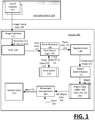
- FIG. 1 illustrates an example system for processing depth images in connection with an interaction plane.
- a depth image processing system 100 can operate in connection with an associated computer system (e.g., see FIG. 5 ) in order to detect and process an interaction as between an object of interest and a designated interaction plane 105.
- system 100 can be implemented with, or as part of a computer system which processes gesture input provided relative to a designated surface that corresponds to the interaction plane 105.
- a user can, for example, make gestures with his hands and/or fingers, or perform other movements relative to the interaction plane 105, which individually or in combination with other movements, serve as input for controlling an application, process or other mechanism of the computer system. While examples described enable better detection and interpretation of gesture input, variations to examples described can include alternative usages and purposes.
- system 100 can be programmed to identify and/or segment objects that are placed on the interaction plane 105.
- the system 100 includes an image interface 110, a filter 120, a plane detection component 130, a segmentation component 140, an object determination component 150, a movement interpretation component 160, and a system input interface 170.
- the image interface 110 can communicate with one no more depth cameras 103, which can monitor a scene that includes the interaction plane 105.
- the interaction plane 105 can correspond to, for example, a region of a tabletop or surface that resides physically under and/or adjacent to the location of the cameras 103.
- the interaction plane 105 can correspond to a multi-sensor region, such as a touch surface provided optically in position with respect to the depth-cameras 103 in order to capture object interaction with the interaction plane 105.
- the image interface 110 can receive a series of image frames 107 from the depth cameras 103.
- the image interface 110 can receive a video clip comprising multiple sequenced image frames 107 from each of the depth cameras 103.
- the image interface 110 can extract image pixel data 111 from each image frame 107, and individual pixels of the image frame 107 can include or be associated with depth data 113 and an image value 115.
- the image value 115 associated with each pixel can correspond to, for example, color (and/or chromacity) or other image based value.
- the image frame 107 can detect a hand or other object of interest interacting with the interaction plane 105.
- the pixel data 111 can be in the form of a pixel cloud, which spatially distributes the pixels based on the depth information relative to the interaction plane 105. While the pixel cloud may be able to sufficiently delineate an object of interest from the interaction plane 105 when the object of interest is a sufficient distance away from the interaction plane, an example of FIG. 1 recognizes that additional processing and logic is needed to decipher pixels which comprise the object of interest when the proximity of the object to the plane is within a threshold in which system error and noise can mask pixels of the object of interest from those of the interaction plane. In particular, an example of FIG.
- system 100 includes functionality and logic which is predicated on the possibility that the interaction between the object of interest and the interaction plane 105 can include the object of interest making contact with the interaction plane 105, or otherwise coming in sufficient proximity to the interaction plane such that discrimination of the object and the interaction plane becomes difficult (e.g., based on the measurement error of the depth camera 103).
- the user can place a hand on the interaction plane 105, and/or make simulated button or key contact with the interaction plane.
- system 100 can determine (i) whether an object that is moved near or on to the interaction plane is the object of interest, (ii) whether the object of interest actually made contact with the interaction plane 105, and/or (iii) spatial characteristics of the object of interest in the particular image frame data 107.
- the filter 120 can implement one or more filtering processes to reduce the noise level of the pixel cloud.
- An example of FIG. 1 recognizes that reduction in noise level can be particularly useful when the object of interest is on or very near the interaction plane 105.
- Filtered pixel data 121 can be provided to the plane detection component 130.
- the plane detection component 130 implements one or more processes to detect a plane from the filtered pixel data 121.
- the plane detection component 130 can include plane detection logic 132 to approximate the pixels of the interaction plane 105 from the image frame 107 that is currently under analysis.
- plane detection logic 132 implements an iterative process (e.g., such as provided by a Random Sample Consensus (“RANSAC”) method) in which randomly selected pixels are analyzed for depth, and optionally image values (e.g., color) in order to converge on a sufficient number of pixels which define a plane within the image.
- RANSAC Random Sample Consensus
- the plane detection logic 132 can implement some assumptions about the location of the interaction plane 105 in the image frame 107, specifically that the interaction plane may have a homogeneous color and further that the interaction plane is depth-wise the furthest object in the image.
- the plane detection logic 132 can determine a plane equation to approximate those pixels of the image frame data which represent the interaction plane 105.
- the system 100 utilizes plane data 131 as between successive or sequential image frames 107 of a common object interaction (e.g., video clip) or session, in order to facilitate approximation of the those pixels which comprise the interaction plane 105 in any given image frame of the captured interaction.
- the plane data 131 can correspond to a plane equation.
- the plane data can correspond to identification of some or all of the pixels which are deemed to be part of the interaction plane 105.
- the plane detection component 130 can operate on an assumption that the location of the interaction plane 105 is static with respect to a given sequence of image frames 107.
- the plane detection component 130 can first check for plane data 131 from a prior relevant image frame 107 in determining the interaction plane 105 of the current image frame 107, where the prior relevant image frame 107 corresponds to (i) a prior image frame 107 (e.g., immediately prior) from a series of image frames of the same object interaction (e.g., video clip which captures a user gesture action), (ii) a prior image frame from a current session, or (iii) a prior image frame from a previous instance of time which is within a threshold time frame.
- the plane detection component 130 can check a plane buffer 135 for plane data 131 of the prior relevant image frame 107.
- the corresponding plane data 131 is used in order to determine updated plane data 133.
- the current plane data 133 can be processed for refinement in regards to the current image frame 107. If no plane data from a prior relevant image frame is identified, then the plane detection logic 132 can be implemented to detect the plane from the pixel point data 121.
- the plane detection component 130 can store the current plane data 131 in the plane buffer for subsequent use.
- the segmentation component 140 can implement a process to use the updated plane data 133 in order to segment pixels of the image frame which correspond to the object of interest from those of the interaction plane 105.
- segmentation component 140 can perform an analysis to identify pixels of like image values 115, which collectively can identify the location and shape of the object of interest.
- the segmentation component 140 can utilize an energy function to approximate a remainder set of pixels which correspond to the object of interest, based on a pixel comparison of color or chromacity.
- the segmentation component 140 can produce a foreground image 141, corresponding to the approximation of the object of interest.
- the foreground image 141 may exclude those pixels which are approximated as belonging to the interaction plane 105, as well as those pixels which have been filtered with the implementation of the filtering component 120 in order to reduce the noise of the respective pixel values (e.g., smooth out noise variations in the depth data of individual pixels).
- the foreground image 141 is subjected to one or more object determination processes of object determination component 150 in order to determine shape, location, spatial characteristics (e.g., two-dimensional dimensions and/or depth map for surface of object), object type, or other characteristics of interest.
- the object type can correspond to the determination as to whether the detected object is an object which should be analyzed or further processed for interpretation.
- system 100 can be implemented to process hand gestures made over the interaction plane, and the detected object can be deemed to have a shape which is not a user hand, in which case the presence of the object in the interaction plane can be ignored (e.g., such as the case when the object of interest is an object that is inadvertently placed on the interaction plane).
- an object data buffer 165 maintains object information 151.
- the object information 151 can include (i) object pixel data 153 (e.g., depth information, image value) of the pixels which approximate the object of interest for a given image frame 107, (ii) object characteristics 155, such as shape, spatial characteristics or object type.
- the object data buffer 165 can also associate confidence values with object pixel data 153 or object characteristics 155.
- the confidence values can be recorded in a variety of contexts, such as from the image camera 103 in context of its approximation of depth information provided with individual pixels, or by way of approximation in terms of the plane detection and/or segmentation.
- the movement interpretation component 160 can utilize buffered object data 161 in order to determine a corresponding input 171 for the system input 170.
- the buffered object data 161 can correspond to representation of multiple detected instances of object information 151, captured over a duration that includes a gesture or other movement of the object of interest, or portion of a gesture/movement.
- the movement interpretation component 160 can access rules 162 and other logic in order to interpret the buffered object data 161.
- the rules 162 can be application or context specific, so that gestures or movements of the object of interest can be interpreted differently based on the determined application or context for which the gesture of movement is to apply to.
- system 170 can perform a programmatic action in response to the corresponding input 171.
- system input 170 can be integrated with the system 100.
- system 100 can be implemented as an accessory or external component which communicates with the computer system where system input 170 resides.
- one or more contact sensors may be combined with the interaction plane 105 in order to determine when the object of interest makes contact with the interaction plane.
- the contact sensor can include, for example, a capacitive sensor, acoustic sensor, or vibrational sensor.
- the detection of objects making contact with the interaction plane 105 enables detection of a more diverse and granular range of motions and gestures from a user's hand or other object of interest.
- FIG. 2 illustrates an example method for processing a series of images to determine an interaction of an object with an interaction plane.
- FIG. 3 illustrates an example method for segmenting an image into an interaction plane and an object of interest.
- FIG. 1 for purpose of illustrating a suitable component or process for performing a step or sub-step being described.
- a series of depth images can be processed which capture an interaction of an object and an interaction plane (210).
- the series of depth images can correspond to a video input which is captured by the depth cameras 103.
- system 100 can receive a video input from the depth cameras 103 which correspond to a user moving his hand or finger in three-dimensions relative to the interaction plane 105.
- system 100 can determine an approximation of pixels which can correspond to the interaction plane (220).
- the plane detection component 130 can, for example, determine an approximation of pixels which form the interaction plane 105 in the depth image (DI n ) in the form of a plane equation.
- pixels of the object of interest can be determined (222).
- the approximation of the pixels corresponding to the object of interest in the depth image (DI n ) can be dependent in part on excluding the pixels which approximate the interaction plane 105.
- the segmentation component 140 uses an energy component to approximate those pixels which correspond to the object of interest.
- the energy equation can equate pixels to correspond to the object of interest based in part on pixel values such as color or chromacity as well as depth.
- a determination can be made as to whether the approximation of the interaction plane 105 from the prior depth image (DI n-1 ) is valid for the current depth image (DI n ) (232).
- the approximation e.g., plane equation
- the process can then be repeated for the next depth image at (230). If the approximation is not valid (236), then the process can be repeated at (220), with re-approximation of the pixels which form the interaction plane 105 and the object of interest.
- the depth camera 103 can capture image frames for a video clip, and each image frame can be processed for pixel information (310).
- the depth camera 103 corresponds to an RGB-D (red blue green depth) camera.
- the depth camera 103 can correspond to an alternative depth image capture device, such as a stereo-pair (or other combination) of non-depth cameras which are combined with image processing to capture depth information.
- Each image pixel can include an image value (312) and depth information (314).
- a filter can be implemented to reduce pixel noise from the pixel information (320).
- a fast filter is applied to smooth a point cloud representation of the image pixels for each image frame.
- the point cloud obtained by off-the-shelf RGB-D cameras tend to contain measurement errors, which can be reduced or normalized using a filtering method.
- the filter can be implemented by, for example, an average (box) filter with an adaptive windows size that is based on distance from the object to the camera.
- the pixel information of the image frame can be further analyzed to detect the interaction plane (330).
- the interaction plane can be determined from a process that starts with either a set of randomly selected pixels (332), or with information previously determined about the interaction plane from a related image frame (e.g., previous image frame of the video clip) (334).
- a temporally coherent version of RANSAC (Random Sample Consensus) algorithm may be used to extract the interaction plane at the start from randomly selected points, so that off-plane objects can be detected.
- RANSAC Random Sample Consensus
- an assumption can be made that the interaction plane is visible to the RGB-D camera except when occluded by off-the plane objects (e.g., including the hands).
- This assumption can be used to model the problem of locating the interaction plane in the image frame as finding the largest plane in a point cloud acquired by the RGB camera 103.
- the percentage of points that belong to the plane is high, and application of the RANSAC tends to converge to identify the interaction plane in just a few iterations.
- a set of three points is randomly selected, and the normal vector a of the plane formed by randomly selected points is computed.
- the plane equation obtained at a given frame is used as an initial estimate in the next frame, avoiding the initial random selection of points. If the plane equation has not changed (or changed just a small amount), the plane may be re-estimated in a single iteration.
- the pipeline for estimating the interaction plane is illustrated in Fig. 1 . With respect to FIG. 4C , a detected plane is shown prior to segmentation.
- off-plane objects can be detected using a segmentation process (340).
- the interaction plane itself can provide a good estimate of the off-plane object.
- the off-plane object is very close to or on the interaction plane, there is only a small difference between the depth of the hand and the plane, and this can cause the part of the off-plane object to be mis-detected.
- a segmentation process can be performed to detect the off-plane object apart from the interaction plane (342).
- the segmentation component 140 can implement a process to determine when the object of interest is on or very close to the interaction plane 105.
- the segmentation process can be a marker-based watershed procedure that can be implemented to combine depth and pixel value (e.g., color or chromacity information).
- a markers-based watershed transform may be used.
- the interaction plane can be estimated again using the RANSAC process, but with a lower threshold (0.25cm in this case), to avoid false positives (i.e. non-planar objects detected as planar).
- the resulting binary image is then eroded to further separate the interaction plane from the object of interest.
- An example of the selection of background and foreground markers is illustrated in Fig. 4D .
- the next step can correspond to defining the energy function to guide the watersheds. Examples recognize that when the object of interest is sufficiently far from the planar surface, the gradient magnitude of the distance from a point to the plane can be sufficient to capture a contour or shape of the object of interest. However, an energy of the object of interest can become progressively smaller as the object of interest gets closer to the interaction plane, in which case additional color information can be used to capture shape or color of the object of interest.
- E u v ⁇ ⁇ d ⁇ + ⁇ ⁇ 2 ⁇ 2 + d 2 ⁇ ⁇ C ⁇
- d is a distance-to-plane function which controls the influence of the chromaticity term, and controls how close to the plane color information starts to be relevant.
- FIG. 4A-4D illustrates an example of a process for recognizing a depth image of a hand placed on an interaction plane.
- An example of FIG. 4A-4D can be implemented using, for example, system 100 such as described with an example of FIG. 1 , or methods such as described with examples of FIG. 2 and FIG. 3 .
- a hand corresponding to an object of interest, is placed on an interaction plane 405.
- One or more depth cameras 410 are positioned to capture images (e.g., video, or series of images) from the interaction plane 405.
- FIG. 4B illustrates a depth-based image of the hand, as captured by the camera 410 when the hand is placed on the interaction plane 405.
- the depth-based image is used to (i) determine an plane approximation of pixels 420 which correspond to the interaction plane 405, and (ii) an approximation of pixels 430 which correspond to the hand placed on the interaction plane 405.
- the plane detection component 130 can determine the plane approximation of pixels 420, as well as the object approximation of pixels 430.
- the approximation of pixels 430 which correspond to the hand are extracted from the background of the interaction plane 405.
- the shape, position and/or proximity of the hand to the interaction plane 405 can be analyzed and correlated to input or other data.
- the characteristics of the hand can be determined from the object approximation of pixels 430 as determined from either the individual image, or for a series of images in which the hand is moved or gestured over or on the interaction plane 405.
- FIG. 5 illustrates an example computer system for implementing one or more examples.
- an example computer 500 can be used to implement the depth image processing system 100 such as described with an example of FIG. 1 , or example methods such as described with FIG. 2 or FIG. 3 .
- the computer system 500 includes at least one processor 504 for processing instructions.
- Computer system 500 also includes a memory 506, such as a random access memory (RAM) or other dynamic storage device, for storing information and instructions to be executed by processor 504.
- the memory 506 can include a persistent storage device 510, such as a magnetic disk or optical disk.
- the memory 506 can also include read-only-memory (ROM).
- a communication interface 518 enables the computer system 500 to communicate with other computers or data processing components or individual wireless devices using, for example, a wireless GSM network or Public Switch Telephony Network (PSTN), over network link 520.
- PSTN Public Switch Telephony Network
- the communication interface 518 enables the computer system 500 to communicate with other services, such as administrative services or with servers of other service providers.
- the computer system 500 also includes a depth camera 540 to capture depth images 519.
- the depth camera 540 can be oriented or directed towards an interaction plane (not shown in FIG. 5 ) in order to capture a movement or gesture of an object with respect to or over the interaction plane 105.
- the memory stores instructions 526 for processing depth images which detect object interactions with respect to or over an interaction plane. The instructions 526 can be executed by the processor 504 in order to analyze depth images 519 captured by the depth camera 540.
- the processor 504 executes one or more sequences of instructions stored in memory 506. Such instructions may be read into memory 506 from another machine-readable medium, such as a storage device. Execution of the sequences of instructions contained in main memory 506 causes processor 504 to perform the process steps described herein. In alternative embodiments, hard-wired circuitry may be used in place of or in combination with software instructions to implement embodiments described herein. Thus, embodiments described are not limited to any specific combination of hardware circuitry and software.
Landscapes
- Engineering & Computer Science (AREA)
- Theoretical Computer Science (AREA)
- Physics & Mathematics (AREA)
- General Engineering & Computer Science (AREA)
- General Physics & Mathematics (AREA)
- Computer Vision & Pattern Recognition (AREA)
- Human Computer Interaction (AREA)
- Multimedia (AREA)
- Software Systems (AREA)
- Computer Hardware Design (AREA)
- Computer Graphics (AREA)
- Life Sciences & Earth Sciences (AREA)
- Bioinformatics & Cheminformatics (AREA)
- Bioinformatics & Computational Biology (AREA)
- Evolutionary Biology (AREA)
- Probability & Statistics with Applications (AREA)
- User Interface Of Digital Computer (AREA)
- Image Analysis (AREA)
- Image Processing (AREA)
Description
- Human computer interfaces currently exist which use depth-based images as a mechanism for determining input. Some computer systems such as the SPROUT, manufactured by HEWLETT PACKARD COMPANY, utilize a depth-based camera in order to detect and analyze objects placed on a designated or associated surface.
-
US 2011/0293137 A1 discloses a method for processing data including receiving a depth map of a scene containing a humanoid form. The depth map is processed so as to identify three-dimensional (3D) connected components in the scene, each connected component including a set of the pixels that are mutually adjacent and have mutually-adjacent depth values. Separate, first and second connected components are identified as both belonging to the humanoid form, and a representation of the humanoid form is generated including both of the first and second connected components. - Haubner, N. et al., "Detecting interaction above digital tabletops using a single depth camera", Machine Vision and Applications, Vol.24, No.8, pp. 1575 - 1587, 2013, discloses the detection of interaction above digital tabletops using a single depth camera (Kinect) mounted above the tabletop.
-
-
FIG. 1 illustrates an example system for processing depth images in connection with an interaction plane. -
FIG. 2 illustrates an example method for processing a series of images to determine an interaction of an object with an interaction plane. -
FIG. 3 illustrates an example method for segmenting an image into an interaction plane and an object of interest. -
FIG. 4A-4D illustrates an example of a process for recognizing a depth image of a hand placed on an interaction plane. -
FIG. 5 illustrates an example computer system for implementing one or more examples. - Examples described herein include a computer readable medium according to
claim 1, a system according to claim 10 and method according to claim 13 for processing a series of depth images which capture an interaction of an object of interest (e.g., user hand) over or relative to an interaction plane. According to some aspects, a depth image processing system and method is described which can analyze and detect a movement of an object with respect to or over an interaction plane, including movement which results in the object making contact with or being in close proximity to the interaction plane. In contrast to some conventional approaches, the proximity of the object of interest with respect to the interaction plane does not hinder the ability of an associated computer system to interpret a gesture or movement of the object with respect to the interaction plane. - According to one aspect, an initial image in a series of images is analyzed. For the initial image, (i) a plane approximation of pixels is determined which correspond to the interaction plane, and (ii) an object approximation of pixels is determined which correspond to the object. The plane approximation of pixels can be determined based at least in part on depth information carried by individual pixels of the initial image. The approximation of object pixels can be determined in one or more images which follow the initial image, based at least in part on the plane approximation of pixels of the initial image.
- With regard to examples described, an "interaction plane" refers to a designated surface over which an object interaction can be imaged and interpreted through depth-image analysis. Many examples described can be implemented with computer systems which are provided or otherwise associated with a defined surface on which user interaction can be received. In such examples, an object of interaction (sometimes referred to as object of interest) can correspond to a user hand, or portion of a hand (e.g., finger) or arm, and the interaction plane marks a surface over which the user forms gestures or performs other movement actions in order to provide input. In contrast to conventional approaches, examples as described enable object detection with respect to the interaction plane when the object is close or on the interaction plane. This enables a more robust and diverse range of inputs and level of human interaction with the associated computer system. While numerous examples described herein provide for the object of interest to correspond to the user's hand, variations provide for a system in which alternative types of objects (e.g., styluses or pens, three-dimensional objects of various types, etc.) can be detected and separately recognized.
- Examples described herein provide that methods, techniques, and actions performed by a computing device are performed programmatically, or as a computer-implemented method. Examples may be implemented as hardware, or a combination of hardware (e.g., a processor(s)) and executable instructions (e.g., stored on a machine-readable storage medium). These instructions can be stored in one or more memory resources of the computing device. A programmatically performed step may or may not be automatic.
- Examples described herein can be implemented using programmatic modules or components. The programmatic modules or components may be any combination of hardware (e.g., processor(s)) and programming to implement the functionalities of the modules or components described herein. In examples described herein, such combinations of hardware and programming may be implemented in a number of different ways. For example, the programming for the components may be processor executable instructions stored on at least one non-transitory machine-readable storage medium and the hardware for the components may include at least one processing resource to execute those instructions. In such examples, the at least one machine-readable storage medium may storage instructions that, when executed by the at least one processing resource, implement the components.
- Some examples described herein can generally involve the use of computing devices, including processing and memory resources. For example, examples described herein may be implemented, in whole or in part, on computing devices such as desktop computers, cellular or smart phones, personal digital assistants (PDAs), laptop computers, printers, digital picture frames, and tablet devices. Memory, processing, and network resources may all be used in connection with the establishment, use, or performance of any example described herein (including with the performance of any method or with the implementation of any system).
- Furthermore, examples described herein may be implemented through the use of instructions that are executable by one or more processors. These instructions may be carried on a computer-readable medium. Machines shown or described with figures below provide examples of processing resources and computer-readable mediums on which instructions for implementing examples described herein can be carried and/or executed. In particular, the numerous machines shown with examples include processor(s) and various forms of memory for holding data and instructions. Examples of computer-readable mediums include permanent memory storage devices, such as hard drives on personal computers or servers. Other examples of computer storage mediums include portable storage units, such as CD or DVD units, flash memory (such as carried on smart phones, multifunctional devices or tablets), and magnetic memory. Computers, terminals, network enabled devices (e.g., mobile devices, such as cell phones) are all examples of machines and devices that utilize processors, memory, and instructions stored on computer-readable mediums. Additionally, examples may be implemented in the form of computer-programs, or a computer usable carrier medium capable of carrying such a program.
-
FIG. 1 illustrates an example system for processing depth images in connection with an interaction plane. In more detail, a depthimage processing system 100 can operate in connection with an associated computer system (e.g., seeFIG. 5 ) in order to detect and process an interaction as between an object of interest and a designatedinteraction plane 105. By way of example,system 100 can be implemented with, or as part of a computer system which processes gesture input provided relative to a designated surface that corresponds to theinteraction plane 105. A user can, for example, make gestures with his hands and/or fingers, or perform other movements relative to theinteraction plane 105, which individually or in combination with other movements, serve as input for controlling an application, process or other mechanism of the computer system. While examples described enable better detection and interpretation of gesture input, variations to examples described can include alternative usages and purposes. By way of example,system 100 can be programmed to identify and/or segment objects that are placed on theinteraction plane 105. - With reference to
FIG. 1 , thesystem 100 includes animage interface 110, afilter 120, aplane detection component 130, asegmentation component 140, anobject determination component 150, amovement interpretation component 160, and asystem input interface 170. Theimage interface 110 can communicate with one no moredepth cameras 103, which can monitor a scene that includes theinteraction plane 105. Theinteraction plane 105 can correspond to, for example, a region of a tabletop or surface that resides physically under and/or adjacent to the location of thecameras 103. In variations, theinteraction plane 105 can correspond to a multi-sensor region, such as a touch surface provided optically in position with respect to the depth-cameras 103 in order to capture object interaction with theinteraction plane 105. In operation, theimage interface 110 can receive a series of image frames 107 from thedepth cameras 103. For example, theimage interface 110 can receive a video clip comprising multiple sequenced image frames 107 from each of thedepth cameras 103. Theimage interface 110 can extractimage pixel data 111 from each image frame 107, and individual pixels of the image frame 107 can include or be associated withdepth data 113 and animage value 115. Theimage value 115 associated with each pixel can correspond to, for example, color (and/or chromacity) or other image based value. - In many applications, the image frame 107 can detect a hand or other object of interest interacting with the
interaction plane 105. Thepixel data 111 can be in the form of a pixel cloud, which spatially distributes the pixels based on the depth information relative to theinteraction plane 105. While the pixel cloud may be able to sufficiently delineate an object of interest from theinteraction plane 105 when the object of interest is a sufficient distance away from the interaction plane, an example ofFIG. 1 recognizes that additional processing and logic is needed to decipher pixels which comprise the object of interest when the proximity of the object to the plane is within a threshold in which system error and noise can mask pixels of the object of interest from those of the interaction plane. In particular, an example ofFIG. 1 recognizes that in many context and usage scenarios, the hand or other object of interest can be placed in contact with, or in close proximity to, theinteraction plane 105, when a gesture or other desired input is being provided by the user. Accordingly,system 100 includes functionality and logic which is predicated on the possibility that the interaction between the object of interest and theinteraction plane 105 can include the object of interest making contact with theinteraction plane 105, or otherwise coming in sufficient proximity to the interaction plane such that discrimination of the object and the interaction plane becomes difficult (e.g., based on the measurement error of the depth camera 103). By way of example, the user can place a hand on theinteraction plane 105, and/or make simulated button or key contact with the interaction plane. Depending on implementation,system 100 can determine (i) whether an object that is moved near or on to the interaction plane is the object of interest, (ii) whether the object of interest actually made contact with theinteraction plane 105, and/or (iii) spatial characteristics of the object of interest in the particular image frame data 107. - According to one aspect, the
filter 120 can implement one or more filtering processes to reduce the noise level of the pixel cloud. An example ofFIG. 1 recognizes that reduction in noise level can be particularly useful when the object of interest is on or very near theinteraction plane 105. Filteredpixel data 121 can be provided to theplane detection component 130. - The
plane detection component 130 implements one or more processes to detect a plane from the filteredpixel data 121. Theplane detection component 130 can includeplane detection logic 132 to approximate the pixels of theinteraction plane 105 from the image frame 107 that is currently under analysis. In one implementation,plane detection logic 132 implements an iterative process (e.g., such as provided by a Random Sample Consensus ("RANSAC") method) in which randomly selected pixels are analyzed for depth, and optionally image values (e.g., color) in order to converge on a sufficient number of pixels which define a plane within the image. Theplane detection logic 132 can implement some assumptions about the location of theinteraction plane 105 in the image frame 107, specifically that the interaction plane may have a homogeneous color and further that the interaction plane is depth-wise the furthest object in the image. Theplane detection logic 132 can determine a plane equation to approximate those pixels of the image frame data which represent theinteraction plane 105. - According to some aspects, the
system 100 utilizesplane data 131 as between successive or sequential image frames 107 of a common object interaction (e.g., video clip) or session, in order to facilitate approximation of the those pixels which comprise theinteraction plane 105 in any given image frame of the captured interaction. By way of example, theplane data 131 can correspond to a plane equation. In variations, the plane data can correspond to identification of some or all of the pixels which are deemed to be part of theinteraction plane 105. In utilizingplane data 131 between successive or sequential image frames, theplane detection component 130 can operate on an assumption that the location of theinteraction plane 105 is static with respect to a given sequence of image frames 107. Accordingly, for a given image frame 107, theplane detection component 130 can first check forplane data 131 from a prior relevant image frame 107 in determining theinteraction plane 105 of the current image frame 107, where the prior relevant image frame 107 corresponds to (i) a prior image frame 107 (e.g., immediately prior) from a series of image frames of the same object interaction (e.g., video clip which captures a user gesture action), (ii) a prior image frame from a current session, or (iii) a prior image frame from a previous instance of time which is within a threshold time frame. Prior to implementingplane detection logic 132, theplane detection component 130 can check aplane buffer 135 forplane data 131 of the prior relevant image frame 107. If a plane was previously detected in a prior image frame 107 of the same sequence, then the correspondingplane data 131 is used in order to determine updatedplane data 133. Thecurrent plane data 133 can be processed for refinement in regards to the current image frame 107. If no plane data from a prior relevant image frame is identified, then theplane detection logic 132 can be implemented to detect the plane from thepixel point data 121. Theplane detection component 130 can store thecurrent plane data 131 in the plane buffer for subsequent use. - The
segmentation component 140 can implement a process to use the updatedplane data 133 in order to segment pixels of the image frame which correspond to the object of interest from those of theinteraction plane 105. In one implementation,segmentation component 140 can perform an analysis to identify pixels of like image values 115, which collectively can identify the location and shape of the object of interest. As described with an example ofFIG. 3 , once the pixels which form theinteraction plane 105 are approximated, thesegmentation component 140 can utilize an energy function to approximate a remainder set of pixels which correspond to the object of interest, based on a pixel comparison of color or chromacity. Thesegmentation component 140 can produce aforeground image 141, corresponding to the approximation of the object of interest. Theforeground image 141 may exclude those pixels which are approximated as belonging to theinteraction plane 105, as well as those pixels which have been filtered with the implementation of thefiltering component 120 in order to reduce the noise of the respective pixel values (e.g., smooth out noise variations in the depth data of individual pixels). - In some implementations, the
foreground image 141 is subjected to one or more object determination processes ofobject determination component 150 in order to determine shape, location, spatial characteristics (e.g., two-dimensional dimensions and/or depth map for surface of object), object type, or other characteristics of interest. The object type can correspond to the determination as to whether the detected object is an object which should be analyzed or further processed for interpretation. For example,system 100 can be implemented to process hand gestures made over the interaction plane, and the detected object can be deemed to have a shape which is not a user hand, in which case the presence of the object in the interaction plane can be ignored (e.g., such as the case when the object of interest is an object that is inadvertently placed on the interaction plane). Furthermore,system 100 can be implemented in context of applications which interpret three-dimensional movement (e.g., three-dimensional hand gestures), and as such, a history of object data may be needed in order to interpret the three-dimensional action. In one implementation, an object data buffer 165 maintainsobject information 151. Theobject information 151 can include (i) object pixel data 153 (e.g., depth information, image value) of the pixels which approximate the object of interest for a given image frame 107, (ii) objectcharacteristics 155, such as shape, spatial characteristics or object type. - In some variations, the object data buffer 165 can also associate confidence values with object pixel data 153 or
object characteristics 155. The confidence values can be recorded in a variety of contexts, such as from theimage camera 103 in context of its approximation of depth information provided with individual pixels, or by way of approximation in terms of the plane detection and/or segmentation. - the
movement interpretation component 160 can utilize bufferedobject data 161 in order to determine acorresponding input 171 for thesystem input 170. The bufferedobject data 161 can correspond to representation of multiple detected instances ofobject information 151, captured over a duration that includes a gesture or other movement of the object of interest, or portion of a gesture/movement. Themovement interpretation component 160 can accessrules 162 and other logic in order to interpret the bufferedobject data 161. By way of example, therules 162 can be application or context specific, so that gestures or movements of the object of interest can be interpreted differently based on the determined application or context for which the gesture of movement is to apply to. - The
system 170 can perform a programmatic action in response to thecorresponding input 171. In some implementations,system input 170 can be integrated with thesystem 100. In variations,system 100 can be implemented as an accessory or external component which communicates with the computer system wheresystem input 170 resides. - In a variation, one or more contact sensors may be combined with the
interaction plane 105 in order to determine when the object of interest makes contact with the interaction plane. The contact sensor can include, for example, a capacitive sensor, acoustic sensor, or vibrational sensor. The detection of objects making contact with theinteraction plane 105 enables detection of a more diverse and granular range of motions and gestures from a user's hand or other object of interest. -
FIG. 2 illustrates an example method for processing a series of images to determine an interaction of an object with an interaction plane.FIG. 3 illustrates an example method for segmenting an image into an interaction plane and an object of interest. In describing an example ofFIG. 2 or FIG. 3 , reference may be made to elements ofFIG. 1 for purpose of illustrating a suitable component or process for performing a step or sub-step being described. - With reference to
FIG. 2 , a series of depth images (DI) can be processed which capture an interaction of an object and an interaction plane (210). The series of depth images can correspond to a video input which is captured by thedepth cameras 103. For example,system 100 can receive a video input from thedepth cameras 103 which correspond to a user moving his hand or finger in three-dimensions relative to theinteraction plane 105. - For a given depth image (DIn) (e.g., initial or first image of a video capture),
system 100 can determine an approximation of pixels which can correspond to the interaction plane (220). Theplane detection component 130 can, for example, determine an approximation of pixels which form theinteraction plane 105 in the depth image (DIn) in the form of a plane equation. Once the plane approximation of pixels is determined, pixels of the object of interest can be determined (222). The approximation of the pixels corresponding to the object of interest in the depth image (DIn) can be dependent in part on excluding the pixels which approximate theinteraction plane 105. In one implementation, thesegmentation component 140 uses an energy component to approximate those pixels which correspond to the object of interest. The energy equation can equate pixels to correspond to the object of interest based in part on pixel values such as color or chromacity as well as depth. - Once the given image is processed, a next or follow on depth image (DIn+1) can be processed as the current image (DIn+1 = DIn), and the approximation of pixels which form the interaction plane from the prior image can be used as a preliminary guess or estimation of the pixels of the
interaction plane 105 in the current image (DIn) (230). In some implementations, a determination can be made as to whether the approximation of theinteraction plane 105 from the prior depth image (DIn-1) is valid for the current depth image (DIn) (232). - If the approximation is valid (234), then the approximation (e.g., plane equation) of the prior depth image (DIn-1) can be carried forward and used in the current depth image (DIn). The process can then be repeated for the next depth image at (230). If the approximation is not valid (236), then the process can be repeated at (220), with re-approximation of the pixels which form the
interaction plane 105 and the object of interest. - With reference to an example of
FIG. 3 , thedepth camera 103 can capture image frames for a video clip, and each image frame can be processed for pixel information (310). In one implementation, thedepth camera 103 corresponds to an RGB-D (red blue green depth) camera. In variations, thedepth camera 103 can correspond to an alternative depth image capture device, such as a stereo-pair (or other combination) of non-depth cameras which are combined with image processing to capture depth information. The pixel information can represent image pixels as u = (u; v)T. Each image pixel can include an image value (312) and depth information (314). The depth information for each image pixel u = (u, v)T can be provided by a three-dimensional spatial point x(u) = (x(u, v), y(u, v), z(u, v))T. In one implementation, the image value of each pixel in the RGB color space can be represented as c ( u ) = (r(u, v), g(u, v), b(u, v))T. - A filter can be implemented to reduce pixel noise from the pixel information (320). In one implementation, a fast filter is applied to smooth a point cloud representation of the image pixels for each image frame. In particular, the point cloud obtained by off-the-shelf RGB-D cameras tend to contain measurement errors, which can be reduced or normalized using a filtering method. The filter can be implemented by, for example, an average (box) filter with an adaptive windows size that is based on distance from the object to the camera.
- The pixel information of the image frame can be further analyzed to detect the interaction plane (330). The interaction plane can be determined from a process that starts with either a set of randomly selected pixels (332), or with information previously determined about the interaction plane from a related image frame (e.g., previous image frame of the video clip) (334). In one variation, a temporally coherent version of RANSAC (Random Sample Consensus) algorithm may be used to extract the interaction plane at the start from randomly selected points, so that off-plane objects can be detected. In extracting the interaction plane, an assumption can be made that the interaction plane is visible to the RGB-D camera except when occluded by off-the plane objects (e.g., including the hands). This assumption can be used to model the problem of locating the interaction plane in the image frame as finding the largest plane in a point cloud acquired by the
RGB camera 103. Typically, the percentage of points that belong to the plane is high, and application of the RANSAC tends to converge to identify the interaction plane in just a few iterations. - According to one implementation, an interaction plan may be represented by a T x = 1, where a = (a1, a2, a3) T is the normal vector of the plane, and x is a 3D point.. Following implementation of the RANSAC process, a set of three points is randomly selected, and the normal vector a of the plane formed by randomly selected points is computed. For all x , the distance

- Assuming that the camera is mostly static (so that a is not expected to change drastically in time), the plane equation obtained at a given frame is used as an initial estimate in the next frame, avoiding the initial random selection of points. If the plane equation has not changed (or changed just a small amount), the plane may be re-estimated in a single iteration. The pipeline for estimating the interaction plane is illustrated in
Fig. 1 . With respect toFIG. 4C , a detected plane is shown prior to segmentation. - Once the interaction plane is determined, off-plane objects can be detected using a segmentation process (340). When the object of interest is off the
interaction plane 105, the interaction plane itself can provide a good estimate of the off-plane object. However, when the off-plane object is very close to or on the interaction plane, there is only a small difference between the depth of the hand and the plane, and this can cause the part of the off-plane object to be mis-detected. - In some variations, a segmentation process can be performed to detect the off-plane object apart from the interaction plane (342). For example, the
segmentation component 140 can implement a process to determine when the object of interest is on or very close to theinteraction plane 105. In one aspect, the segmentation process can be a marker-based watershed procedure that can be implemented to combine depth and pixel value (e.g., color or chromacity information). To obtain a contour or shape of an off-plane object (e.g., the hand), a markers-based watershed transform may be used. The interaction plane can be estimated again using the RANSAC process, but with a lower threshold (0.25cm in this case), to avoid false positives (i.e. non-planar objects detected as planar). The resulting binary image is then eroded to further separate the interaction plane from the object of interest. An example of the selection of background and foreground markers is illustrated inFig. 4D . Given the appropriate markers, the next step can correspond to defining the energy function to guide the watersheds. Examples recognize that when the object of interest is sufficiently far from the planar surface, the gradient magnitude of the distance from a point to the plane can be sufficient to capture a contour or shape of the object of interest. However, an energy of the object of interest can become progressively smaller as the object of interest gets closer to the interaction plane, in which case additional color information can be used to capture shape or color of the object of interest. - It should be noticed that in some usage scenarios involving interaction with passive planar surfaces (e.g. a table), the light source is typically above the interaction plane. This arrangement can cast shadows from the object of interest onto the surface. Examples recognize further that in such cases, pixel values which are based on color can also capture shadows. Accordingly, in some examples, the pixel values that are used include chromaticity information. More precisely, we use the CIE L∗a∗b color space and the desired chromaticity map is given by


-
FIG. 4A-4D illustrates an example of a process for recognizing a depth image of a hand placed on an interaction plane. An example ofFIG. 4A-4D can be implemented using, for example,system 100 such as described with an example ofFIG. 1 , or methods such as described with examples ofFIG. 2 and FIG. 3 . InFIG. 4A , a hand, corresponding to an object of interest, is placed on aninteraction plane 405. One ormore depth cameras 410 are positioned to capture images (e.g., video, or series of images) from theinteraction plane 405. -
FIG. 4B illustrates a depth-based image of the hand, as captured by thecamera 410 when the hand is placed on theinteraction plane 405. InFIG. 4C , the depth-based image is used to (i) determine an plane approximation ofpixels 420 which correspond to theinteraction plane 405, and (ii) an approximation ofpixels 430 which correspond to the hand placed on theinteraction plane 405. For example, theplane detection component 130 can determine the plane approximation ofpixels 420, as well as the object approximation ofpixels 430. - In
FIG. 4D , the approximation ofpixels 430 which correspond to the hand are extracted from the background of theinteraction plane 405. The shape, position and/or proximity of the hand to theinteraction plane 405 can be analyzed and correlated to input or other data. The characteristics of the hand can be determined from the object approximation ofpixels 430 as determined from either the individual image, or for a series of images in which the hand is moved or gestured over or on theinteraction plane 405. -
FIG. 5 illustrates an example computer system for implementing one or more examples. In particular, anexample computer 500 can be used to implement the depthimage processing system 100 such as described with an example ofFIG. 1 , or example methods such as described withFIG. 2 or FIG. 3 . Thecomputer system 500 includes at least oneprocessor 504 for processing instructions.Computer system 500 also includes amemory 506, such as a random access memory (RAM) or other dynamic storage device, for storing information and instructions to be executed byprocessor 504. Thememory 506 can include apersistent storage device 510, such as a magnetic disk or optical disk. Thememory 506 can also include read-only-memory (ROM). Acommunication interface 518 enables thecomputer system 500 to communicate with other computers or data processing components or individual wireless devices using, for example, a wireless GSM network or Public Switch Telephony Network (PSTN), overnetwork link 520. As an alternative or addition, thecommunication interface 518 enables thecomputer system 500 to communicate with other services, such as administrative services or with servers of other service providers. - In an example of
FIG. 5 , thecomputer system 500 also includes adepth camera 540 to capture depth images 519. As described with some other examples, thedepth camera 540 can be oriented or directed towards an interaction plane (not shown inFIG. 5 ) in order to capture a movement or gesture of an object with respect to or over theinteraction plane 105. In an example ofFIG. 5 , thememory stores instructions 526 for processing depth images which detect object interactions with respect to or over an interaction plane. Theinstructions 526 can be executed by theprocessor 504 in order to analyze depth images 519 captured by thedepth camera 540. - In an example of
FIG. 5 , theprocessor 504 executes one or more sequences of instructions stored inmemory 506. Such instructions may be read intomemory 506 from another machine-readable medium, such as a storage device. Execution of the sequences of instructions contained inmain memory 506 causesprocessor 504 to perform the process steps described herein. In alternative embodiments, hard-wired circuitry may be used in place of or in combination with software instructions to implement embodiments described herein. Thus, embodiments described are not limited to any specific combination of hardware circuitry and software. - Although illustrative embodiments have been described in detail herein with reference to the accompanying drawings, variations to specific embodiments and details are encompassed by this disclosure. It is intended that the scope of embodiments described herein be defined by the claims.
Claims (13)
- A non-transitory computer readable medium that stores instructions for processing depth images which capture an interaction of an object relative to an interaction plane (105), the instructions being executable by one or more processors (504) of a computing device to cause the computing device to perform operations that comprise:(a) processing (210) a series of depth images which capture the interaction of the object relative to the interaction plane;(b) determining, for an initial image of the series, (i) a plane approximation of pixels (220) which correspond to the interaction plane, and (ii) an object approximation of pixels (222) which correspond to the object, the plane and object approximation of pixels for the initial image being determined at least in part from depth information carried by individual pixels of the initial image;(c) determining (230), in one or more images which follow the initial image, an object approximation of pixels which correspond to the object, based at least in part on the plane approximation of pixels which corresponds to the interaction plane as determined for the initial image;(d) segmenting, in the initial image and the one or more images that follow the initial image, the object from the interaction plane using at least the object approximation of pixels, wherein the segmenting operation further comprises: detecting (324) an off-plane object apart from the interaction plane by using a markers-based watershed transform based on the depth information and pixel value; and(e) interpreting the interaction as input for the computing device based at least in part on determining information about at least one of a shape or proximity of the object relative to the interaction plane.
- The non-transitory computer readable medium of Claim 1, wherein (b) includes determining at least one of the plane approximation of pixels or the object approximation of pixels using color information associated with individual pixels of the initial image.
- The non-transitory computer readable medium of Claim 1, wherein (b) includes determining the object approximation of pixels using color information associated with individual pixels of each of the one or more images which follow the initial image.
- The non-transitory computer readable medium of Claim 1, further comprising instructions, that when executed by the one or more processors, cause the computing device to perform operations that comprise:
filtering (320) at least one of the initial image, or each of the one or more images which follow the initial image, in order to filter out a select set of pixels which are deemed noisy. - The non-transitory computer readable medium of Claim 1, wherein at least one of (b) or (c) include determining at least one of the plane approximation of pixels or the object approximation of pixels using an energy equation that utilizes at least one of color or depth information.
- The non-transitory computer readable medium of Claim 1, wherein (a) includes using a red green blue depth (RGB-D) camera (130).
- The non-transitory computer readable medium of Claim 1, further comprising instructions, which when executed by one or more processors of the computing device, cause the computing device to perform operations that include:
for a second image that follows the initial image in time, making a determination as to whether the plane approximation of pixels for the interaction plane is accurate based at least in part on depth information carried by individual pixels of the second image; and wherein making the determination is performed for the second image in response to determining that the plane approximation of pixels for the interaction plane is valid for the second image. - The non-transitory computer readable medium of Claim 7, wherein when the plane approximation of the interaction plane is determined to not be valid, then the instructions are executable by the one or more processors to perform operations that comprise:
determining, for either the second image or a subsequent image, a plane approximation of pixels which correspond to the interaction plane. - The non-transitory computer readable medium of Claim 7, wherein making the determination is based at least in part on color values of individual pixels of the second image.
- A computer system (500) comprising:one or more processors (504);memory resources (506) that store a set of instructions;one or more cameras (540) that are directed to capture depth images from an interaction plane (105);wherein the one or more processors use instructions stored in the memory resources to:process a series of depth images which capture the interaction of an object relative to the interaction plane;determine, for an initial image of the series, (i) a plane approximation of pixels which correspond to the interaction plane, and (ii) an object approximation of pixels which correspond to the object, the plane and object approximation of pixels for the initial image being determined at least in part from depth information carried by individual pixels of the initial image;determine, in one or more images which follow the initial image, an object approximation of pixels which correspond to the object, based at least in part on the plane approximation of pixels which corresponds to the interaction plane as determined for the initial image;segment, in the initial image and the one or more images that follow the initial image, the object from the interaction plane using at least the object approximation of pixels, wherein the segmenting operation further comprises: detecting (324) an off-plane object apart from the interaction plane by using a markers-based watershed transform based on the depth information and pixel value; andinterpret the interaction as input for the computing device based at least in part on determining information about at least one of a shape or proximity of the object relative to the interaction plane.
- The computer system of claim 10, wherein the one or more cameras are each red-green-blue (RGB) depth cameras.
- The computer system of claim 10, further comprising an input interface which processes information about the object interacting with the interaction plane based on the object approximation of pixels from at least the initial image or one or more follow on images.
- A computer-implemented method for processing an interaction of an object relative to an interaction plane (105), the method being implemented by one or more processors (504) and comprising:(a) processing (210) a series of depth images which capture the interaction of the object relative to the interaction plane;(b) determining (220), for an initial image of the series, (i) a plane approximation of pixels which correspond to the interaction plane, and (ii) an object approximation of pixels (222) which correspond to the object, the plane and object approximation of pixels for the initial image being determined at least in part from depth information carried by individual pixels of the initial image;(c) determining (230), in one or more images which follow the initial image, an object approximation of pixels which correspond to the object, based at least in part on the plane approximation of pixels which corresponds to the interaction plane as determined for the initial image;(d) segmenting, in the initial image and the one or more images that follow the initial image, the object from the interaction plane using at least the object approximation of pixels, wherein the segmenting operation further comprises: detecting (324) an off-plane object apart from the interaction plane by using a markers-based watershed transform based on the depth information and pixel value; and(e) interpreting the interaction as input for the computing device based at least in part on determining information about at least one of a shape or proximity of the object relative to the interaction plane.
Applications Claiming Priority (1)
| Application Number | Priority Date | Filing Date | Title |
|---|---|---|---|
| PCT/US2015/028346 WO2016175801A1 (en) | 2015-04-29 | 2015-04-29 | System and method for processing depth images which capture an interaction of an object relative to an interaction plane |
Publications (3)
| Publication Number | Publication Date |
|---|---|
| EP3231175A1 EP3231175A1 (en) | 2017-10-18 |
| EP3231175A4 EP3231175A4 (en) | 2018-06-27 |
| EP3231175B1 true EP3231175B1 (en) | 2021-02-24 |
Family
ID=57198700
Family Applications (1)
| Application Number | Title | Priority Date | Filing Date |
|---|---|---|---|
| EP15890933.3A Not-in-force EP3231175B1 (en) | 2015-04-29 | 2015-04-29 | System and method for processing depth images which capture an interaction of an object relative to an interaction plane |
Country Status (4)
| Country | Link |
|---|---|
| US (1) | US10269136B2 (en) |
| EP (1) | EP3231175B1 (en) |
| CN (1) | CN107209556B (en) |
| WO (1) | WO2016175801A1 (en) |
Families Citing this family (7)
| Publication number | Priority date | Publication date | Assignee | Title |
|---|---|---|---|---|
| JP6942566B2 (en) * | 2017-08-30 | 2021-09-29 | キヤノン株式会社 | Information processing equipment, information processing methods and computer programs |
| US10580807B2 (en) * | 2017-10-24 | 2020-03-03 | Stmicroelectronics, Inc. | Color pixel and range pixel combination unit |
| CN108470173B (en) * | 2018-04-17 | 2021-06-15 | 北京矿冶科技集团有限公司 | Ore particle segmentation method |
| US11454975B2 (en) * | 2018-06-28 | 2022-09-27 | Uatc, Llc | Providing actionable uncertainties in autonomous vehicles |
| US10937325B2 (en) * | 2018-12-27 | 2021-03-02 | Intel Corporation | Collision avoidance system, depth imaging system, vehicle, obstacle map generator, and methods thereof |
| CN110135331A (en) * | 2019-05-13 | 2019-08-16 | 人加智能机器人技术(北京)有限公司 | Interbehavior detection method, device, system, equipment and storage medium |
| WO2023283934A1 (en) * | 2021-07-16 | 2023-01-19 | Huawei Technologies Co.,Ltd. | Devices and methods for gesture-based selection |
Family Cites Families (20)
| Publication number | Priority date | Publication date | Assignee | Title |
|---|---|---|---|---|
| JP3037432B2 (en) | 1993-11-01 | 2000-04-24 | カドラックス・インク | Food cooking method and cooking device using lightwave oven |
| US8072470B2 (en) | 2003-05-29 | 2011-12-06 | Sony Computer Entertainment Inc. | System and method for providing a real-time three-dimensional interactive environment |
| KR100894874B1 (en) * | 2007-01-10 | 2009-04-24 | 주식회사 리얼이미지 | Apparatus and Method for Generating a Stereoscopic Image from a Two-Dimensional Image using the Mesh Map |
| US8175379B2 (en) | 2008-08-22 | 2012-05-08 | Adobe Systems Incorporated | Automatic video image segmentation |
| KR101738569B1 (en) * | 2009-02-17 | 2017-05-22 | 인텔 코포레이션 | Method and system for gesture recognition |
| US20100302365A1 (en) * | 2009-05-29 | 2010-12-02 | Microsoft Corporation | Depth Image Noise Reduction |
| US8594425B2 (en) | 2010-05-31 | 2013-11-26 | Primesense Ltd. | Analysis of three-dimensional scenes |
| US8751215B2 (en) * | 2010-06-04 | 2014-06-10 | Microsoft Corporation | Machine based sign language interpreter |
| CN102402687B (en) * | 2010-09-13 | 2016-06-15 | 三星电子株式会社 | Rigid body part direction detection method and device based on depth information |
| US9628755B2 (en) * | 2010-10-14 | 2017-04-18 | Microsoft Technology Licensing, Llc | Automatically tracking user movement in a video chat application |
| US9329469B2 (en) * | 2011-02-17 | 2016-05-03 | Microsoft Technology Licensing, Llc | Providing an interactive experience using a 3D depth camera and a 3D projector |
| JP6074170B2 (en) * | 2011-06-23 | 2017-02-01 | インテル・コーポレーション | Short range motion tracking system and method |
| US9146398B2 (en) * | 2011-07-12 | 2015-09-29 | Microsoft Technology Licensing, Llc | Providing electronic communications in a physical world |
| US9111351B2 (en) * | 2011-12-15 | 2015-08-18 | Sony Corporation | Minimizing drift using depth camera images |
| US9117295B2 (en) * | 2011-12-20 | 2015-08-25 | Adobe Systems Incorporated | Refinement of depth maps by fusion of multiple estimates |
| US20140104394A1 (en) | 2012-10-15 | 2014-04-17 | Intel Corporation | System and method for combining data from multiple depth cameras |
| CN102997891B (en) * | 2012-11-16 | 2015-04-29 | 上海光亮光电科技有限公司 | Device and method for measuring scene depth |
| CN105359518B (en) * | 2013-02-18 | 2017-03-08 | 株式会社匹突匹银行 | Image processing apparatus and image processing method |
| US20140354602A1 (en) | 2013-04-12 | 2014-12-04 | Impression.Pi, Inc. | Interactive input system and method |
| KR102224715B1 (en) | 2013-10-14 | 2021-03-09 | 삼성전자주식회사 | 3D interaction apparatus, display device including the same, and method of driving the same |
-
2015
- 2015-04-29 WO PCT/US2015/028346 patent/WO2016175801A1/en not_active Ceased
- 2015-04-29 US US15/542,882 patent/US10269136B2/en not_active Expired - Fee Related
- 2015-04-29 CN CN201580073234.1A patent/CN107209556B/en not_active Expired - Fee Related
- 2015-04-29 EP EP15890933.3A patent/EP3231175B1/en not_active Not-in-force
Non-Patent Citations (1)
| Title |
|---|
| HAUBNER NADIA ET AL: "Detecting interaction above digital tabletops using a single depth camera", MACHINE VISION AND APPLICATIONS, SPRINGER VERLAG, DE, vol. 24, no. 8, 24 August 2013 (2013-08-24), pages 1575 - 1587, XP035368920, ISSN: 0932-8092, [retrieved on 20130824], DOI: 10.1007/S00138-013-0538-5 * |
Also Published As
| Publication number | Publication date |
|---|---|
| US20180047182A1 (en) | 2018-02-15 |
| EP3231175A1 (en) | 2017-10-18 |
| WO2016175801A1 (en) | 2016-11-03 |
| US10269136B2 (en) | 2019-04-23 |
| CN107209556A (en) | 2017-09-26 |
| EP3231175A4 (en) | 2018-06-27 |
| CN107209556B (en) | 2020-10-16 |
Similar Documents
| Publication | Publication Date | Title |
|---|---|---|
| US10269136B2 (en) | System and method for processing depth images which capture an interaction of an object relative to an interaction plane | |
| JP6501092B2 (en) | Image processing apparatus and method for foreground mask correction for object segmentation | |
| KR101722803B1 (en) | Method, computer program, and device for hybrid tracking of real-time representations of objects in image sequence | |
| US10853928B2 (en) | Image fusion processing module | |
| US9560271B2 (en) | Removing unwanted objects from photographed image | |
| US10853927B2 (en) | Image fusion architecture | |
| US9639943B1 (en) | Scanning of a handheld object for 3-dimensional reconstruction | |
| EP2079009A1 (en) | Apparatus and methods for a touch user interface using an image sensor | |
| WO2017112041A1 (en) | Morphological and edge filters for depth edge enhancement in digital images | |
| KR20100138602A (en) | Apparatus and method for detecting a hand of a subject in real time | |
| KR102598459B1 (en) | Lost foot recovery of human objects from image sequences based on horizon detection. | |
| WO2016029399A1 (en) | Object selection based on region of interest fusion | |
| US20180068451A1 (en) | Systems and methods for creating a cinemagraph | |
| WO2016200711A1 (en) | Determination of exposure time for an image frame | |
| CN111476812A (en) | Map segmentation method, device, pose estimation method and device terminal | |
| US9916042B2 (en) | Fingertip position estimation apparatus and method | |
| CN104268864A (en) | Card edge extracting method and device | |
| WO2023201512A1 (en) | Gesture recognition method and interaction method, gesture interaction system, electronic device, and storage medium | |
| JP5887264B2 (en) | Object recognition apparatus, method, program, and computer-readable medium storing the software | |
| EP3211599A1 (en) | Adaptive depth-guided non-photorealistic rendering method, corresponding computer program product, computer-readable carrier medium and device | |
| CN104933688B (en) | A data processing method and electronic device | |
| CN112146578B (en) | Scale ratio calculation method, device, equipment and storage medium | |
| KR101491413B1 (en) | Method for generating 3d coordinate using finger image from mono camera in terminal and mobile terminal for generating 3d coordinate using finger image from mono camera | |
| Meng et al. | Building smart cameras on mobile tablets for hand gesture recognition | |
| KR101382806B1 (en) | Method for generating 3d coordinate using finger image from camera in terminal and mobile terminal for generating 3d coordinate using finger image from camera |
Legal Events
| Date | Code | Title | Description |
|---|---|---|---|
| STAA | Information on the status of an ep patent application or granted ep patent |
Free format text: STATUS: THE INTERNATIONAL PUBLICATION HAS BEEN MADE |
|
| PUAI | Public reference made under article 153(3) epc to a published international application that has entered the european phase |
Free format text: ORIGINAL CODE: 0009012 |
|
| STAA | Information on the status of an ep patent application or granted ep patent |
Free format text: STATUS: REQUEST FOR EXAMINATION WAS MADE |
|
| 17P | Request for examination filed |
Effective date: 20170712 |
|
| AK | Designated contracting states |
Kind code of ref document: A1 Designated state(s): AL AT BE BG CH CY CZ DE DK EE ES FI FR GB GR HR HU IE IS IT LI LT LU LV MC MK MT NL NO PL PT RO RS SE SI SK SM TR |
|
| AX | Request for extension of the european patent |
Extension state: BA ME |
|
| A4 | Supplementary search report drawn up and despatched |
Effective date: 20180528 |
|
| RIC1 | Information provided on ipc code assigned before grant |
Ipc: G06T 7/215 20170101ALI20180522BHEP Ipc: H04N 13/00 20060101AFI20180522BHEP Ipc: G06T 7/155 20170101ALI20180522BHEP Ipc: G06T 7/77 20170101ALI20180522BHEP Ipc: G06T 7/194 20170101ALI20180522BHEP Ipc: G06T 7/11 20170101ALI20180522BHEP |
|
| DAV | Request for validation of the european patent (deleted) | ||
| DAX | Request for extension of the european patent (deleted) | ||
| RAP1 | Party data changed (applicant data changed or rights of an application transferred) |
Owner name: HEWLETT-PACKARD DEVELOPMENT COMPANY, L.P. |
|
| STAA | Information on the status of an ep patent application or granted ep patent |
Free format text: STATUS: EXAMINATION IS IN PROGRESS |
|
| 17Q | First examination report despatched |
Effective date: 20191114 |
|
| REG | Reference to a national code |
Ref country code: DE Ref legal event code: R079 Ref document number: 602015066198 Country of ref document: DE Free format text: PREVIOUS MAIN CLASS: H04N0013020000 Ipc: G06T0007155000 |
|
| RIC1 | Information provided on ipc code assigned before grant |
Ipc: G06F 3/03 20060101ALI20200717BHEP Ipc: G06T 19/00 20110101ALI20200717BHEP Ipc: H04N 13/00 20180101ALI20200717BHEP Ipc: G06T 7/194 20170101ALI20200717BHEP Ipc: G06T 7/11 20170101ALI20200717BHEP Ipc: G06T 7/215 20170101ALI20200717BHEP Ipc: G06F 3/042 20060101ALI20200717BHEP Ipc: G06T 7/77 20170101ALI20200717BHEP Ipc: G06F 3/01 20060101ALI20200717BHEP Ipc: G06T 7/155 20170101AFI20200717BHEP |
|
| GRAP | Despatch of communication of intention to grant a patent |
Free format text: ORIGINAL CODE: EPIDOSNIGR1 |
|
| STAA | Information on the status of an ep patent application or granted ep patent |
Free format text: STATUS: GRANT OF PATENT IS INTENDED |
|
| GRAJ | Information related to disapproval of communication of intention to grant by the applicant or resumption of examination proceedings by the epo deleted |
Free format text: ORIGINAL CODE: EPIDOSDIGR1 |
|
| STAA | Information on the status of an ep patent application or granted ep patent |
Free format text: STATUS: EXAMINATION IS IN PROGRESS |
|
| INTG | Intention to grant announced |
Effective date: 20200914 |
|
| GRAP | Despatch of communication of intention to grant a patent |
Free format text: ORIGINAL CODE: EPIDOSNIGR1 |
|
| STAA | Information on the status of an ep patent application or granted ep patent |
Free format text: STATUS: GRANT OF PATENT IS INTENDED |
|
| INTC | Intention to grant announced (deleted) | ||
| INTG | Intention to grant announced |
Effective date: 20201029 |
|
| GRAS | Grant fee paid |
Free format text: ORIGINAL CODE: EPIDOSNIGR3 |
|
| GRAA | (expected) grant |
Free format text: ORIGINAL CODE: 0009210 |
|
| STAA | Information on the status of an ep patent application or granted ep patent |
Free format text: STATUS: THE PATENT HAS BEEN GRANTED |
|
| AK | Designated contracting states |
Kind code of ref document: B1 Designated state(s): AL AT BE BG CH CY CZ DE DK EE ES FI FR GB GR HR HU IE IS IT LI LT LU LV MC MK MT NL NO PL PT RO RS SE SI SK SM TR |
|
| REG | Reference to a national code |
Ref country code: CH Ref legal event code: EP |
|
| REG | Reference to a national code |
Ref country code: DE Ref legal event code: R096 Ref document number: 602015066198 Country of ref document: DE |
|
| REG | Reference to a national code |
Ref country code: AT Ref legal event code: REF Ref document number: 1365434 Country of ref document: AT Kind code of ref document: T Effective date: 20210315 |
|
| REG | Reference to a national code |
Ref country code: IE Ref legal event code: FG4D |
|
| PGFP | Annual fee paid to national office [announced via postgrant information from national office to epo] |
Ref country code: GB Payment date: 20210324 Year of fee payment: 7 |
|
| REG | Reference to a national code |
Ref country code: LT Ref legal event code: MG9D |
|
| REG | Reference to a national code |
Ref country code: NL Ref legal event code: MP Effective date: 20210224 |
|
| PG25 | Lapsed in a contracting state [announced via postgrant information from national office to epo] |
Ref country code: FI Free format text: LAPSE BECAUSE OF FAILURE TO SUBMIT A TRANSLATION OF THE DESCRIPTION OR TO PAY THE FEE WITHIN THE PRESCRIBED TIME-LIMIT Effective date: 20210224 Ref country code: HR Free format text: LAPSE BECAUSE OF FAILURE TO SUBMIT A TRANSLATION OF THE DESCRIPTION OR TO PAY THE FEE WITHIN THE PRESCRIBED TIME-LIMIT Effective date: 20210224 Ref country code: GR Free format text: LAPSE BECAUSE OF FAILURE TO SUBMIT A TRANSLATION OF THE DESCRIPTION OR TO PAY THE FEE WITHIN THE PRESCRIBED TIME-LIMIT Effective date: 20210525 Ref country code: LT Free format text: LAPSE BECAUSE OF FAILURE TO SUBMIT A TRANSLATION OF THE DESCRIPTION OR TO PAY THE FEE WITHIN THE PRESCRIBED TIME-LIMIT Effective date: 20210224 Ref country code: BG Free format text: LAPSE BECAUSE OF FAILURE TO SUBMIT A TRANSLATION OF THE DESCRIPTION OR TO PAY THE FEE WITHIN THE PRESCRIBED TIME-LIMIT Effective date: 20210524 Ref country code: NO Free format text: LAPSE BECAUSE OF FAILURE TO SUBMIT A TRANSLATION OF THE DESCRIPTION OR TO PAY THE FEE WITHIN THE PRESCRIBED TIME-LIMIT Effective date: 20210524 Ref country code: PT Free format text: LAPSE BECAUSE OF FAILURE TO SUBMIT A TRANSLATION OF THE DESCRIPTION OR TO PAY THE FEE WITHIN THE PRESCRIBED TIME-LIMIT Effective date: 20210624 |
|
| PGFP | Annual fee paid to national office [announced via postgrant information from national office to epo] |
Ref country code: DE Payment date: 20210323 Year of fee payment: 7 |
|
| REG | Reference to a national code |
Ref country code: AT Ref legal event code: MK05 Ref document number: 1365434 Country of ref document: AT Kind code of ref document: T Effective date: 20210224 |
|
| PG25 | Lapsed in a contracting state [announced via postgrant information from national office to epo] |
Ref country code: SE Free format text: LAPSE BECAUSE OF FAILURE TO SUBMIT A TRANSLATION OF THE DESCRIPTION OR TO PAY THE FEE WITHIN THE PRESCRIBED TIME-LIMIT Effective date: 20210224 Ref country code: PL Free format text: LAPSE BECAUSE OF FAILURE TO SUBMIT A TRANSLATION OF THE DESCRIPTION OR TO PAY THE FEE WITHIN THE PRESCRIBED TIME-LIMIT Effective date: 20210224 Ref country code: NL Free format text: LAPSE BECAUSE OF FAILURE TO SUBMIT A TRANSLATION OF THE DESCRIPTION OR TO PAY THE FEE WITHIN THE PRESCRIBED TIME-LIMIT Effective date: 20210224 Ref country code: LV Free format text: LAPSE BECAUSE OF FAILURE TO SUBMIT A TRANSLATION OF THE DESCRIPTION OR TO PAY THE FEE WITHIN THE PRESCRIBED TIME-LIMIT Effective date: 20210224 Ref country code: RS Free format text: LAPSE BECAUSE OF FAILURE TO SUBMIT A TRANSLATION OF THE DESCRIPTION OR TO PAY THE FEE WITHIN THE PRESCRIBED TIME-LIMIT Effective date: 20210224 |
|
| PG25 | Lapsed in a contracting state [announced via postgrant information from national office to epo] |
Ref country code: IS Free format text: LAPSE BECAUSE OF FAILURE TO SUBMIT A TRANSLATION OF THE DESCRIPTION OR TO PAY THE FEE WITHIN THE PRESCRIBED TIME-LIMIT Effective date: 20210624 |
|
| PG25 | Lapsed in a contracting state [announced via postgrant information from national office to epo] |
Ref country code: CZ Free format text: LAPSE BECAUSE OF FAILURE TO SUBMIT A TRANSLATION OF THE DESCRIPTION OR TO PAY THE FEE WITHIN THE PRESCRIBED TIME-LIMIT Effective date: 20210224 Ref country code: EE Free format text: LAPSE BECAUSE OF FAILURE TO SUBMIT A TRANSLATION OF THE DESCRIPTION OR TO PAY THE FEE WITHIN THE PRESCRIBED TIME-LIMIT Effective date: 20210224 Ref country code: SM Free format text: LAPSE BECAUSE OF FAILURE TO SUBMIT A TRANSLATION OF THE DESCRIPTION OR TO PAY THE FEE WITHIN THE PRESCRIBED TIME-LIMIT Effective date: 20210224 Ref country code: AT Free format text: LAPSE BECAUSE OF FAILURE TO SUBMIT A TRANSLATION OF THE DESCRIPTION OR TO PAY THE FEE WITHIN THE PRESCRIBED TIME-LIMIT Effective date: 20210224 |
|
| REG | Reference to a national code |
Ref country code: DE Ref legal event code: R097 Ref document number: 602015066198 Country of ref document: DE |
|
| PG25 | Lapsed in a contracting state [announced via postgrant information from national office to epo] |
Ref country code: MC Free format text: LAPSE BECAUSE OF FAILURE TO SUBMIT A TRANSLATION OF THE DESCRIPTION OR TO PAY THE FEE WITHIN THE PRESCRIBED TIME-LIMIT Effective date: 20210224 Ref country code: DK Free format text: LAPSE BECAUSE OF FAILURE TO SUBMIT A TRANSLATION OF THE DESCRIPTION OR TO PAY THE FEE WITHIN THE PRESCRIBED TIME-LIMIT Effective date: 20210224 Ref country code: RO Free format text: LAPSE BECAUSE OF FAILURE TO SUBMIT A TRANSLATION OF THE DESCRIPTION OR TO PAY THE FEE WITHIN THE PRESCRIBED TIME-LIMIT Effective date: 20210224 Ref country code: SK Free format text: LAPSE BECAUSE OF FAILURE TO SUBMIT A TRANSLATION OF THE DESCRIPTION OR TO PAY THE FEE WITHIN THE PRESCRIBED TIME-LIMIT Effective date: 20210224 |
|
| PG25 | Lapsed in a contracting state [announced via postgrant information from national office to epo] |
Ref country code: LU Free format text: LAPSE BECAUSE OF NON-PAYMENT OF DUE FEES Effective date: 20210429 |
|
| PLBE | No opposition filed within time limit |
Free format text: ORIGINAL CODE: 0009261 |
|
| STAA | Information on the status of an ep patent application or granted ep patent |
Free format text: STATUS: NO OPPOSITION FILED WITHIN TIME LIMIT |
|
| REG | Reference to a national code |
Ref country code: BE Ref legal event code: MM Effective date: 20210430 |
|
| PG25 | Lapsed in a contracting state [announced via postgrant information from national office to epo] |
Ref country code: LI Free format text: LAPSE BECAUSE OF NON-PAYMENT OF DUE FEES Effective date: 20210430 Ref country code: CH Free format text: LAPSE BECAUSE OF NON-PAYMENT OF DUE FEES Effective date: 20210430 Ref country code: AL Free format text: LAPSE BECAUSE OF FAILURE TO SUBMIT A TRANSLATION OF THE DESCRIPTION OR TO PAY THE FEE WITHIN THE PRESCRIBED TIME-LIMIT Effective date: 20210224 Ref country code: ES Free format text: LAPSE BECAUSE OF FAILURE TO SUBMIT A TRANSLATION OF THE DESCRIPTION OR TO PAY THE FEE WITHIN THE PRESCRIBED TIME-LIMIT Effective date: 20210224 Ref country code: FR Free format text: LAPSE BECAUSE OF NON-PAYMENT OF DUE FEES Effective date: 20210430 |
|
| 26N | No opposition filed |
Effective date: 20211125 |
|
| PG25 | Lapsed in a contracting state [announced via postgrant information from national office to epo] |
Ref country code: SI Free format text: LAPSE BECAUSE OF FAILURE TO SUBMIT A TRANSLATION OF THE DESCRIPTION OR TO PAY THE FEE WITHIN THE PRESCRIBED TIME-LIMIT Effective date: 20210224 |
|
| PG25 | Lapsed in a contracting state [announced via postgrant information from national office to epo] |
Ref country code: IT Free format text: LAPSE BECAUSE OF FAILURE TO SUBMIT A TRANSLATION OF THE DESCRIPTION OR TO PAY THE FEE WITHIN THE PRESCRIBED TIME-LIMIT Effective date: 20210224 Ref country code: IE Free format text: LAPSE BECAUSE OF NON-PAYMENT OF DUE FEES Effective date: 20210429 |
|
| PG25 | Lapsed in a contracting state [announced via postgrant information from national office to epo] |
Ref country code: IS Free format text: LAPSE BECAUSE OF FAILURE TO SUBMIT A TRANSLATION OF THE DESCRIPTION OR TO PAY THE FEE WITHIN THE PRESCRIBED TIME-LIMIT Effective date: 20210624 |
|
| PG25 | Lapsed in a contracting state [announced via postgrant information from national office to epo] |
Ref country code: BE Free format text: LAPSE BECAUSE OF NON-PAYMENT OF DUE FEES Effective date: 20210430 |
|
| REG | Reference to a national code |
Ref country code: DE Ref legal event code: R119 Ref document number: 602015066198 Country of ref document: DE |
|
| GBPC | Gb: european patent ceased through non-payment of renewal fee |
Effective date: 20220429 |
|
| PG25 | Lapsed in a contracting state [announced via postgrant information from national office to epo] |
Ref country code: GB Free format text: LAPSE BECAUSE OF NON-PAYMENT OF DUE FEES Effective date: 20220429 Ref country code: DE Free format text: LAPSE BECAUSE OF NON-PAYMENT OF DUE FEES Effective date: 20221103 |
|
| PG25 | Lapsed in a contracting state [announced via postgrant information from national office to epo] |
Ref country code: HU Free format text: LAPSE BECAUSE OF FAILURE TO SUBMIT A TRANSLATION OF THE DESCRIPTION OR TO PAY THE FEE WITHIN THE PRESCRIBED TIME-LIMIT; INVALID AB INITIO Effective date: 20150429 |
|
| PG25 | Lapsed in a contracting state [announced via postgrant information from national office to epo] |
Ref country code: CY Free format text: LAPSE BECAUSE OF FAILURE TO SUBMIT A TRANSLATION OF THE DESCRIPTION OR TO PAY THE FEE WITHIN THE PRESCRIBED TIME-LIMIT Effective date: 20210224 |
|
| PG25 | Lapsed in a contracting state [announced via postgrant information from national office to epo] |
Ref country code: MK Free format text: LAPSE BECAUSE OF FAILURE TO SUBMIT A TRANSLATION OF THE DESCRIPTION OR TO PAY THE FEE WITHIN THE PRESCRIBED TIME-LIMIT Effective date: 20210224 |
|
| PG25 | Lapsed in a contracting state [announced via postgrant information from national office to epo] |
Ref country code: MT Free format text: LAPSE BECAUSE OF FAILURE TO SUBMIT A TRANSLATION OF THE DESCRIPTION OR TO PAY THE FEE WITHIN THE PRESCRIBED TIME-LIMIT Effective date: 20210224 |
|
| PG25 | Lapsed in a contracting state [announced via postgrant information from national office to epo] |
Ref country code: TR Free format text: LAPSE BECAUSE OF FAILURE TO SUBMIT A TRANSLATION OF THE DESCRIPTION OR TO PAY THE FEE WITHIN THE PRESCRIBED TIME-LIMIT Effective date: 20210224 |