EP3231072B1 - Commutator motor, method for producing a commutator motor, and windscreen-wiper motor - Google Patents
Commutator motor, method for producing a commutator motor, and windscreen-wiper motor Download PDFInfo
- Publication number
- EP3231072B1 EP3231072B1 EP15807674.5A EP15807674A EP3231072B1 EP 3231072 B1 EP3231072 B1 EP 3231072B1 EP 15807674 A EP15807674 A EP 15807674A EP 3231072 B1 EP3231072 B1 EP 3231072B1
- Authority
- EP
- European Patent Office
- Prior art keywords
- winding
- armature
- wire
- slots
- wire section
- Prior art date
- Legal status (The legal status is an assumption and is not a legal conclusion. Google has not performed a legal analysis and makes no representation as to the accuracy of the status listed.)
- Active
Links
- 238000004519 manufacturing process Methods 0.000 title claims description 5
- 238000004804 winding Methods 0.000 claims description 83
- 238000000034 method Methods 0.000 claims description 5
- 238000011161 development Methods 0.000 description 2
- 230000018109 developmental process Effects 0.000 description 2
- 238000012986 modification Methods 0.000 description 2
- 230000004048 modification Effects 0.000 description 2
- OKTJSMMVPCPJKN-UHFFFAOYSA-N Carbon Chemical compound [C] OKTJSMMVPCPJKN-UHFFFAOYSA-N 0.000 description 1
- 229910052799 carbon Inorganic materials 0.000 description 1
- 239000000470 constituent Substances 0.000 description 1
- 239000002966 varnish Substances 0.000 description 1
Images

Classifications
-
- H—ELECTRICITY
- H02—GENERATION; CONVERSION OR DISTRIBUTION OF ELECTRIC POWER
- H02K—DYNAMO-ELECTRIC MACHINES
- H02K23/00—DC commutator motors or generators having mechanical commutator; Universal AC/DC commutator motors
- H02K23/26—DC commutator motors or generators having mechanical commutator; Universal AC/DC commutator motors characterised by the armature windings
-
- H—ELECTRICITY
- H02—GENERATION; CONVERSION OR DISTRIBUTION OF ELECTRIC POWER
- H02K—DYNAMO-ELECTRIC MACHINES
- H02K23/00—DC commutator motors or generators having mechanical commutator; Universal AC/DC commutator motors
- H02K23/26—DC commutator motors or generators having mechanical commutator; Universal AC/DC commutator motors characterised by the armature windings
- H02K23/30—DC commutator motors or generators having mechanical commutator; Universal AC/DC commutator motors characterised by the armature windings having lap or loop windings
-
- H—ELECTRICITY
- H02—GENERATION; CONVERSION OR DISTRIBUTION OF ELECTRIC POWER
- H02K—DYNAMO-ELECTRIC MACHINES
- H02K15/00—Processes or apparatus specially adapted for manufacturing, assembling, maintaining or repairing of dynamo-electric machines
- H02K15/08—Forming windings by laying conductors into or around core parts
- H02K15/085—Forming windings by laying conductors into or around core parts by laying conductors into slotted stators
-
- H—ELECTRICITY
- H02—GENERATION; CONVERSION OR DISTRIBUTION OF ELECTRIC POWER
- H02K—DYNAMO-ELECTRIC MACHINES
- H02K23/00—DC commutator motors or generators having mechanical commutator; Universal AC/DC commutator motors
- H02K23/40—DC commutator motors or generators having mechanical commutator; Universal AC/DC commutator motors characterised by the arrangement of the magnet circuits
-
- H—ELECTRICITY
- H02—GENERATION; CONVERSION OR DISTRIBUTION OF ELECTRIC POWER
- H02K—DYNAMO-ELECTRIC MACHINES
- H02K3/00—Details of windings
- H02K3/04—Windings characterised by the conductor shape, form or construction, e.g. with bar conductors
- H02K3/28—Layout of windings or of connections between windings
Definitions
- the invention relates to a commutator motor in accordance with the preamble of Claim 1. Furthermore, the invention relates to a method for producing a commutator motor according to the invention, and to a windscreen-wiper motor which has a commutator motor according to the invention.
- a commutator motor in accordance with the preamble of Claim 1 and a method for producing a commutator motor of this type are known from US 8,378,547 B2 .
- the known commutator motor has four magnet elements which are arranged on a reference-circle diameter around an axis of rotation of an armature shaft with polarity that alternates in the circumferential direction.
- the armature comprises a plurality of winding wires, each winding wire having two winding-wire sections which are arranged in the region of different magnet elements in such a manner that a first winding-wire section is assigned to a first magnet element and a second winding-wire section is assigned to a second magnet element which adjoins the first magnet element in the circumferential direction.
- the two magnet elements which follow one another in the circumferential direction have different polarities, it is necessary to configure the winding directions of the two winding-wire sections differently. To this end, for example, it can be gathered from Figs 19 and 21 of the document in question that the two winding-wire sections have an armature slot, in which the two winding-wire sections are arranged jointly. Since the magnet elements do not adjoin one another directly as viewed in the circumferential direction, but rather are separated from one another by way of a gap which runs in the longitudinal direction, relatively low-noise commutation with a satisfactory degree of efficiency results in practice in the case of a winding design of this type.
- the invention is based on the object of developing a commutator motor in accordance with the preamble of Claim 1 in such a way that an alternative embodiment of the commutator motor is achieved with satisfactory noise behaviour and a high degree of efficiency.
- this object is achieved by virtue of the fact that the windings of the two winding-wire sections intersect in such a manner that the windings of the one winding-wire section are located in each case in an armature slot, which are located between the armature slots of the windings of the other winding-wire section.
- the armature slot of the one winding-wire section is located directly beside an armature slot of the other winding-wire section.
- the winding wire is optimized within the context of the available intersection variants, since the respective winding-wire section is assigned as far as possible to its respective magnet element and interacts with the latter.
- the armature has eighteen armature teeth, and that the one winding-wire section is arranged in two armature slots, which are separated from one another by three armature slots, as viewed in the circumferential direction of the armature, and that the other winding-wire section is arranged in two armature slots which are separated from one another by four armature slots as viewed in the circumferential direction of the armature.
- each winding-wire section is at least substantially approximately the same, preferably is the same.
- the invention also comprises a method for producing a commutator motor according to the invention, in which a winding-wire section of a winding wire is arranged in a first winding direction in two armature slots of an armature in a first winding step and subsequently another winding-wire section of the winding wire is arranged in a reverse winding direction compared to the first winding direction in two armature slots of the armature in a second winding step.
- the windings of the two winding-wire sections intersect as viewed in the circumferential direction of the armature slots in such a manner that after carrying out the first winding step the winding wire is introduced into an armature slot in order to carry out the second winding step, which armature slot is arranged between the armature slots of the first winding-wire section.
- the invention also comprises a windscreen-wiper motor which has a commutator motor according to the invention, and a commutator which was produced in accordance with a method according to the invention.
- Fig. 1 shows a commutator motor 10 according to the invention which serves as a constituent part in a windscreen-wiper motor 100.
- the commutator motor 10 is received within a housing 1 of the windscreen-wiper motor 100 and has an armature 15 with an armature shaft 2 which is mounted in a plurality of bearing devices 3, 4 within the housing 1.
- armature 15 with an armature shaft 2 which is mounted in a plurality of bearing devices 3, 4 within the housing 1.
- four permanent magnet elements 11, 12, 13, 14 are arranged by way of example within the housing 1 on its inner wall, between which permanent magnet elements 11, 12, 13, 14 gaps are formed which run in each case in the longitudinal direction and separate the permanent magnet elements 11, 12, 13, 14 from one another.
- the commutator motor 10 is therefore configured as what is known as a four-pole motor.
- a multiplicity of armature plates 5 which are stacked above one another and are arranged flush with respect to one another are situated in a known manner on the armature 15.
- the armature plates 5 which are connected to one another for example, by way of a baked varnish have eighteen armature teeth Z1 to Z18 which protrude radially to the outside at uniform angular spacings and eighteen armature slots N1 to N18 which are arranged between the armature teeth Z1 to Z18.
- the armature teeth Z1 to Z18 are widened in a T-shaped manner in a known way at their radially outer end region.
- the armature 15 has a total of eighteen commutator hooks H1 to H18, of which not all commutator hooks H1 to H18 can be seen in Figs 2 and 4 on account of the illustration, however.
- the commutator hooks H1 to H18 are connected in an electrically conducting manner to coils C1 to C9 which are arranged in the armature slots N1 to N18, for example by way of a welded or brazed connection of the respective start 21 and end 22 of a winding wire 20 which forms the respective coil C1 to C9.
- Nine winding wires 20 are therefore provided to form the coils C1 to C9.
- the commutator hooks H1 to H18 are connected in an electrically conducting manner to current segments 7 which in turn interact with a brush device which, according to Fig. 1 , has two brush elements B1, B2 in the form of carbon brushes which, by way of example but not restrictively, are arranged offset with respect to one another by 180°, and which are force-loaded against the current segments 7 by way of spring force.
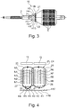
- the commutator motor 10 is distinguished by a special winding type which will be explained in greater detail in the following text using Figs 2 and 4 : it can be seen in Fig. 4 , in particular, that a winding wire 20 which forms the coil C4 makes electrical contact with a start 21 (by way of example) on the commutator hook H4 and by way of its end 22 on the commutator hook H5.
- the winding wire 20 has two winding-wire sections 25, 26. Whereas the first winding-wire section 25 which is assigned to the permanent magnet element 11 has a winding direction which runs in the clockwise direction, the second winding-wire section 26 which is assigned to the permanent magnet element 12 is wound in a winding direction which runs counter to the clockwise direction.
- the first winding-wire section 25 is arranged in the armature slots N1 and N5, whereas the second winding-wire section 26 is arranged in the armature slots N4 and N9.
- Three separating armatures slots N2, N3 and N4 are arranged between the two armature slots N1 and N5 of the first winding-wire section 25, whereas four separating armature slots N5, N6, N7 and N8 are arranged between the two armature slots N4 and N9 of the second winding-wire section 26.
- Each of the two winding-wire sections 25, 26 has a multiplicity of windings 27, 28, the number of windings 27, 28 preferably being at least approximately identical.
- the configuration of the coil C4 with the two winding-wire sections 25, 26 takes place by way of example in accordance with Fig. 4 by virtue of the fact that first of all the start 21 of the winding wire 20 is connected to the commutator hook H4. Subsequently, the first winding-wire section 25 is inserted with the windings 27 into the armature slots N1 and N5. Afterwards (that is to say, after the configuration of the required number of windings 27), the winding wire 20 is guided back into the armature slot N4 with a simultaneous reversal of rotational direction and arrangement of the windings 28 of the second winding-wire section 26 in the armature slots N4 and N9.
- the end 22 is connected to the commutator hook H5.
- the other coils C1 to C3 and C5 to C9 are introduced into the armature slots N1 to N18 according to the same winding design.
- the commutator motor 10 which has been described up to now can be converted or modified in a wide variety of ways without deviating from the concept of the invention.
Landscapes
- Engineering & Computer Science (AREA)
- Power Engineering (AREA)
- Manufacturing & Machinery (AREA)
- Dc Machiner (AREA)
- Manufacture Of Motors, Generators (AREA)
- Windings For Motors And Generators (AREA)
Description
- The invention relates to a commutator motor in accordance with the preamble of
Claim 1. Furthermore, the invention relates to a method for producing a commutator motor according to the invention, and to a windscreen-wiper motor which has a commutator motor according to the invention. - A commutator motor in accordance with the preamble of
Claim 1 and a method for producing a commutator motor of this type are known fromUS 8,378,547 B2 . The known commutator motor has four magnet elements which are arranged on a reference-circle diameter around an axis of rotation of an armature shaft with polarity that alternates in the circumferential direction. Moreover, the armature comprises a plurality of winding wires, each winding wire having two winding-wire sections which are arranged in the region of different magnet elements in such a manner that a first winding-wire section is assigned to a first magnet element and a second winding-wire section is assigned to a second magnet element which adjoins the first magnet element in the circumferential direction. Since the two magnet elements which follow one another in the circumferential direction have different polarities, it is necessary to configure the winding directions of the two winding-wire sections differently. To this end, for example, it can be gathered from Figs 19 and 21 of the document in question that the two winding-wire sections have an armature slot, in which the two winding-wire sections are arranged jointly. Since the magnet elements do not adjoin one another directly as viewed in the circumferential direction, but rather are separated from one another by way of a gap which runs in the longitudinal direction, relatively low-noise commutation with a satisfactory degree of efficiency results in practice in the case of a winding design of this type. - Proceeding from the described prior art, the invention is based on the object of developing a commutator motor in accordance with the preamble of
Claim 1 in such a way that an alternative embodiment of the commutator motor is achieved with satisfactory noise behaviour and a high degree of efficiency. - According to the invention, in a commutator motor having the characterizing features of
Claim 1, this object is achieved by virtue of the fact that the windings of the two winding-wire sections intersect in such a manner that the windings of the one winding-wire section are located in each case in an armature slot, which are located between the armature slots of the windings of the other winding-wire section. - In contrast to the prior art mentioned at the outset, no armature slot is therefore provided, in which the windings of the two winding-wire sections are arranged at the same time. Rather, an intersection of the two winding-wire sections takes place in such a way that, as viewed in the circumferential direction, there is an intersection of the two winding-wire sections, the intersection being formed at least by one armature tooth.
- Advantageous developments of the commutator motor according to the invention are specified in the subclaims. All combinations comprising at least two of the features disclosed in the claims, the description and/or the figures fall within the scope of the invention.
- It is provided in one particularly preferred structural embodiment that the armature slot of the one winding-wire section is located directly beside an armature slot of the other winding-wire section. In other words, this means that, as viewed in the circumferential direction of the armature, the intersection between the two winding-wire sections is configured to be as small as possible. As a result, the winding wire is optimized within the context of the available intersection variants, since the respective winding-wire section is assigned as far as possible to its respective magnet element and interacts with the latter.
- Furthermore, it is provided, in particular, that between the armature slots of the one winding-wire section and the armature slots of the other winding-wire section in each case at least one additional armature slot is arranged.
- Here, it can be provided, in particular, that the number of the additional or separating armature slots of the two winding-wire sections is different.
- In a concrete embodiment or development of the last-mentioned proposal, it is provided that the armature has eighteen armature teeth, and that the one winding-wire section is arranged in two armature slots, which are separated from one another by three armature slots, as viewed in the circumferential direction of the armature, and that the other winding-wire section is arranged in two armature slots which are separated from one another by four armature slots as viewed in the circumferential direction of the armature. In the case of a four-pole motor with four magnet elements which have in each case the same circumferential length as viewed in the circumferential direction, this results in a relatively homogeneous arrangement or distribution of the winding-wire sections with respect to the magnet elements and, as a consequence, a relatively high degree of efficiency with satisfactory noise properties of the commutator motor.
- It is likewise particularly preferably provided that the number of windings of each winding-wire section is at least substantially approximately the same, preferably is the same.
- The invention also comprises a method for producing a commutator motor according to the invention, in which a winding-wire section of a winding wire is arranged in a first winding direction in two armature slots of an armature in a first winding step and subsequently another winding-wire section of the winding wire is arranged in a reverse winding direction compared to the first winding direction in two armature slots of the armature in a second winding step. It is provided according to the invention that the windings of the two winding-wire sections intersect as viewed in the circumferential direction of the armature slots in such a manner that after carrying out the first winding step the winding wire is introduced into an armature slot in order to carry out the second winding step, which armature slot is arranged between the armature slots of the first winding-wire section.
- It is provided in one preferred embodiment of the method according to the invention that between the armature slots of the one winding-wire section and the armature slots of the other winding-wire section in each case at least one further armature slot is arranged, wherein the number of the further armature slots is different, and that in the first winding step, the winding-wire section is formed, which has the smaller number of separating armature slots. This method is particularly advantageous in that the greater the number of separating armature slots in one winding-wire section, the greater the tendency that the winding wire is guided or runs in the direction of the armature shaft during winding, which is to be considered disadvantageous for winding-specific and for physical reasons.
- The invention also comprises a windscreen-wiper motor which has a commutator motor according to the invention, and a commutator which was produced in accordance with a method according to the invention.
- Further advantages, features and details of the invention result from the following description of preferred exemplary embodiments and using the drawing, in which:
- Fig. 1
- shows a longitudinal section through a commutator motor according to the invention in the form of a windscreen-wiper motor,
- Fig. 2
- shows a cross section through the commutator motor according to
Fig. 1 in the armature region, - Fig. 3
- shows an armature which is used in the commutator motor according to
Fig. 1 in an individual illustration and in side view, and - Fig. 4
- shows a diagrammatic illustration for clarifying the winding design according to the invention in a commutator motor according to the invention.
- Identical elements or elements with an identical function are provided with the same reference numerals in the figures.
-
Fig. 1 shows acommutator motor 10 according to the invention which serves as a constituent part in a windscreen-wiper motor 100. Thecommutator motor 10 is received within ahousing 1 of the windscreen-wiper motor 100 and has anarmature 15 with anarmature shaft 2 which is mounted in a plurality ofbearing devices housing 1. As can be seen, in particular, usingFig. 2 , fourpermanent magnet elements housing 1 on its inner wall, between whichpermanent magnet elements permanent magnet elements commutator motor 10 is therefore configured as what is known as a four-pole motor. Moreover, it is essential that the polarities of the fourpermanent magnet elements - In a modification of the exemplary embodiment which is shown, it can also be provided that, instead of four
permanent magnet elements - A multiplicity of
armature plates 5 which are stacked above one another and are arranged flush with respect to one another are situated in a known manner on thearmature 15. As can be seen, in particular, usingFig. 2 , thearmature plates 5 which are connected to one another, for example, by way of a baked varnish have eighteen armature teeth Z1 to Z18 which protrude radially to the outside at uniform angular spacings and eighteen armature slots N1 to N18 which are arranged between the armature teeth Z1 to Z18. The armature teeth Z1 to Z18 are widened in a T-shaped manner in a known way at their radially outer end region. - It can be seen from a combination of
Figs 3 and 4 that, moreover, thearmature 15 has a total of eighteen commutator hooks H1 to H18, of which not all commutator hooks H1 to H18 can be seen inFigs 2 and4 on account of the illustration, however. The commutator hooks H1 to H18 are connected in an electrically conducting manner to coils C1 to C9 which are arranged in the armature slots N1 to N18, for example by way of a welded or brazed connection of therespective start 21 andend 22 of a windingwire 20 which forms the respective coil C1 to C9. Ninewinding wires 20 are therefore provided to form the coils C1 to C9. The commutator hooks H1 to H18 are connected in an electrically conducting manner tocurrent segments 7 which in turn interact with a brush device which, according toFig. 1 , has two brush elements B1, B2 in the form of carbon brushes which, by way of example but not restrictively, are arranged offset with respect to one another by 180°, and which are force-loaded against thecurrent segments 7 by way of spring force. - The
commutator motor 10 according to the invention is distinguished by a special winding type which will be explained in greater detail in the following text usingFigs 2 and4 : it can be seen inFig. 4 , in particular, that awinding wire 20 which forms the coil C4 makes electrical contact with a start 21 (by way of example) on the commutator hook H4 and by way of itsend 22 on the commutator hook H5. The windingwire 20 has two winding-wire sections wire section 25 which is assigned to thepermanent magnet element 11 has a winding direction which runs in the clockwise direction, the second winding-wire section 26 which is assigned to thepermanent magnet element 12 is wound in a winding direction which runs counter to the clockwise direction. Moreover, it can be seen inFigs 2 and4 that the first winding-wire section 25 is arranged in the armature slots N1 and N5, whereas the second winding-wire section 26 is arranged in the armature slots N4 and N9. Three separating armatures slots N2, N3 and N4 are arranged between the two armature slots N1 and N5 of the first winding-wire section 25, whereas four separating armature slots N5, N6, N7 and N8 are arranged between the two armature slots N4 and N9 of the second winding-wire section 26. It can therefore be gathered from the drawings, in particular, that the two winding-wire sections - Each of the two winding-
wire sections windings windings - The configuration of the coil C4 with the two winding-
wire sections Fig. 4 by virtue of the fact that first of all thestart 21 of thewinding wire 20 is connected to the commutator hook H4. Subsequently, the first winding-wire section 25 is inserted with thewindings 27 into the armature slots N1 and N5. Afterwards (that is to say, after the configuration of the required number of windings 27), the windingwire 20 is guided back into the armature slot N4 with a simultaneous reversal of rotational direction and arrangement of thewindings 28 of the second winding-wire section 26 in the armature slots N4 and N9. After configuration of the required number ofwindings 28 of the second winding-wire section 26, theend 22 is connected to the commutator hook H5. The other coils C1 to C3 and C5 to C9 are introduced into the armature slots N1 to N18 according to the same winding design. - In a modification of the winding design which is shown and described, it can also be provided that first of all the
windings 28 of that winding-wire section 26 which has the greater number of separating armature slots N1 to N18 are configured, and that subsequently, after corresponding guiding back of thewinding wire 20, theother windings 27 or the other winding-wire section 25 are/is configured. - The
commutator motor 10 which has been described up to now can be converted or modified in a wide variety of ways without deviating from the concept of the invention. -
- 1
- Housing
- 2
- Armature shaft
- 3, 4
- Bearing device
- 5
- Armature plate
- 7
- Current segment
- 10
- Commutator motor
- 11 to 14
- Permanent magnet element
- 15
- Armature
- 20
- Winding wire
- 21
- Start
- 22
- End
- 25, 26
- Winding-wire section
- 27,28
- Winding
- 100
- Windscreen-wiper motor
- Z1 to Z18
- Armature tooth
- B1, B2
- Brush element
- N1 to N18
- Armature slot
- H1 to H18
- Commutator hook
- C1 to C9
- Coil
Claims (9)
- A commutator motor (10) having at least four magnet elements (11 to 14) which are arranged on a reference-circle diameter around an axis of rotation of an armature shaft (2) with polarity that alternates in the circumferential direction, and having an armature (15) with armature slots (N1 to N18) and armature teeth (Z1 to Z18), wherein winding wires (20) having a multiplicity of windings (27, 28) in each case for constructing coils (C1 to C9) are arranged in the armature slots (N1 to N18), wherein a start (21) and an end (22) of a winding wire (20) is electrically conductively connected to a commutator hook (H1 to H18) in each case, wherein a winding wire (20) has two winding-wire sections (25, 26), which are arranged in the region of different magnet elements (11 to 14) in such a manner that a first winding-wire section (25) with a first number of windings (27) in a first winding direction is assigned to a first magnet element (11 to 14) and interacts with the first magnet element (11 to 14) and is located in two armature slots (N1 to N18), and that a second winding-wire section (26) with a second number of windings (28) in a second winding direction, opposite to the first winding direction, is assigned to a second magnet element (11 to 14) and interacts with the second magnet element (11 to 14) and is located in two armature slots (N1 to N18), and wherein the first and the second magnet elements (11 to 14) are adjacent magnet elements (11 to 14) and have different polarities,
characterised
in that the windings (27, 28) of the two winding-wire sections (25, 26) intersect in such a manner that the windings (27, 28) of the one winding-wire section (25, 26) are located in an armature slot (N1 to N18), which is located between the armature slots (N1 to N18) of the windings (28, 27) of the other winding-wire section (26, 25). - The commutator motor according to Claim 1, characterised in that in the intersection area of winding-wire sections (25, 26), the armature slot (N1 to N18) of the one winding-wire section (25, 26) is located directly beside the armature slot (N1 to N18) of the other winding-wire section (26, 25).
- The commutator motor according to Claim 1 or 2, characterised in that in an area remote from the intersection area of winding-wire sections (25, 26), between the armature slot (N1 to N18) of the one winding-wire section (25, 26) and the armature slot (N1 to N18) of the other winding-wire section (26, 25) at least one additional armature slot (N1 to N18) is arranged.
- The commutator motor according to one of Claims 1 to 3, characterised in that the number of the armature slots (N1 to N18) of the two winding-wire sections (25, 26) is different.
- The commutator motor according to Claim 4, characterised in that the armature (15) has eighteen armature teeth (Z1 to Z18), and in that the one winding-wire section (25) is arranged in two armature slots (N1, N5), which are separated from one another by three armature slots (N2 to N4), as viewed in the circumferential direction of the armature (15), and in that the other winding-wire section (26) is arranged in two armature slots (N4, N9), which are separated from one another by four armature slots (N5 to N8), as viewed in the circumferential direction of the armature (15).
- The commutator motor according to one of Claims 1 to 5, characterised in that the number of windings (27, 28) of the two winding-wire sections (25, 26) is at least substantially the same, preferably is the same.
- A method for producing a commutator motor (10), wherein the commutator motor (10) is provided having at least four magnet elements (11 to 14) which are arranged on a reference-circle diameter around an axis of rotation of an armature shaft (2) with polarity that alternates in the circumferential direction, and having an armature (15) with armature slots (N1 to N18) and armature teeth (Z1 to Z18), wherein winding wires (20) having a multiplicity of windings (27, 28) in each case for constructing coils (C1 to C9) are arranged in the armature slots (N1 to N18), wherein a start (21) and an end (22) of a winding wire (20) is electrically conductively connected to a commutator hook (H1 to H18) in each case, wherein a winding wire (20) has two winding-wire sections (25, 26), which are arranged in the region of different magnet elements (11 to 14) in such a manner that a first winding-wire section (25) with a first number of windings (27) in a first winding direction is assigned to a first magnet element (11 to 14) and interacts with the first magnet element (11 to 14) and is located in two armature slots (N1 to N18), and that a second winding-wire section (26) with a second number of windings (28) in a second winding direction, opposite to the first winding direction, is assigned to a second magnet element (11 to 14) and interacts with the second magnet element (11 to 14) and is located in two armature slots (N1 to N18), and wherein the first and the second magnet elements (11 to 14) are adjacent magnet elements (11 to 14) and have different polarities,
wherein the first winding-wire section (25) of a winding wire (20) is arranged in a first winding direction in two armature slots (N1, N5) of the armature (15) in a first winding step and subsequently the second winding-wire section (26) of the winding wire (20) is arranged in a reverse direction compared to the first winding direction in two armature slots (N4, N9) of the armature (15) in a second winding step, characterized in that
the windings (27, 28) of the two winding-wire sections (25, 26) intersect as viewed in the circumferential direction of the armature slots (N1 to N18) in such a manner that after carrying out the first winding step the winding wire (20) is introduced into an armature slot (N4) in order to carry out the second winding step, which armature slot (N4) is arranged between the armature slots (N1, N5) of the first winding-wire section (25) so that the windings (27, 28) of the two winding-wire sections (25, 26) are located in an armature slot (N1 to N18), which is located between the armature slots (N1 to N18) of the windings (28, 27) of the other winding-wire section (26, 25). - The method according to Claim 7, characterised in that between the two armature slots (N1, N5) of the first winding-wire section (25) a first number of armature slots (N2 to N4) is arranged, and between the two armature slots (N4, N9) of the second winding-wire section (26) a second number of armature slots (N5 to N8) is arranged, wherein the first number of armature slots (N2 to N4) of the first winding-wire section (25) and the second number of armature slots (N5 to N8) of the second winding-wire section (26) is different, and in that in the first winding step, the first winding-wire section (25) is formed so that the first number of armature slots (N2 to N4) is smaller than the second number of armature slots (N5 to N8).
- A windscreen-wiper motor (100), which has a commutator motor (10) according to one of Claims 1 to 6 and/or is produced according to a method according to Claim 7 or 8.
Applications Claiming Priority (2)
| Application Number | Priority Date | Filing Date | Title |
|---|---|---|---|
| DE102014118185.9A DE102014118185A1 (en) | 2014-12-09 | 2014-12-09 | Commutator motor, method of manufacturing a commutator motor and wiper motor |
| PCT/EP2015/079169 WO2016091979A1 (en) | 2014-12-09 | 2015-12-09 | Commutator motor, method for producing a commutator motor, and windscreen-wiper motor |
Publications (2)
| Publication Number | Publication Date |
|---|---|
| EP3231072A1 EP3231072A1 (en) | 2017-10-18 |
| EP3231072B1 true EP3231072B1 (en) | 2020-06-10 |
Family
ID=54838365
Family Applications (1)
| Application Number | Title | Priority Date | Filing Date |
|---|---|---|---|
| EP15807674.5A Active EP3231072B1 (en) | 2014-12-09 | 2015-12-09 | Commutator motor, method for producing a commutator motor, and windscreen-wiper motor |
Country Status (6)
| Country | Link |
|---|---|
| US (1) | US10374501B2 (en) |
| EP (1) | EP3231072B1 (en) |
| JP (1) | JP6655620B2 (en) |
| CN (1) | CN107005136B (en) |
| DE (1) | DE102014118185A1 (en) |
| WO (1) | WO2016091979A1 (en) |
Families Citing this family (1)
| Publication number | Priority date | Publication date | Assignee | Title |
|---|---|---|---|---|
| US12316176B2 (en) * | 2021-11-17 | 2025-05-27 | Baker Hughes Oilfield Operations Llc | Method for external winding of ESP motor using a split core stator |
Family Cites Families (13)
| Publication number | Priority date | Publication date | Assignee | Title |
|---|---|---|---|---|
| US4541575A (en) * | 1982-09-14 | 1985-09-17 | Kollmorgen Technologies Corp. | Winding technique for multiple winding brushless motors |
| US7274126B2 (en) * | 2000-06-14 | 2007-09-25 | Black & Decker Inc. | Motor armature having distributed windings for reducing arcing |
| JP4772508B2 (en) * | 2004-02-10 | 2011-09-14 | 株式会社ミツバ | Electric motor |
| JP4781653B2 (en) * | 2004-10-21 | 2011-09-28 | 株式会社マキタ | Electric tool |
| DE102006011547A1 (en) * | 2006-03-14 | 2007-09-20 | Robert Bosch Gmbh | Electric machine |
| JP2009124850A (en) * | 2007-11-14 | 2009-06-04 | Asmo Co Ltd | Direct current motor |
| CN101978580B (en) * | 2008-03-24 | 2014-04-30 | 株式会社美姿把 | windshield wiper motor |
| JP5414318B2 (en) * | 2008-06-30 | 2014-02-12 | 株式会社ミツバ | Electric motor |
| JP5231879B2 (en) * | 2008-06-30 | 2013-07-10 | 株式会社ミツバ | Electric motor |
| USRE45912E1 (en) | 2008-06-30 | 2016-03-01 | Mitsuba Corporation | Electric motor |
| JP5595277B2 (en) * | 2008-10-07 | 2014-09-24 | 株式会社ミツバ | Electric motor and motor with reduction gear |
| JP2013090437A (en) * | 2011-10-18 | 2013-05-13 | Mitsuba Corp | Electric motor |
| US9209672B2 (en) * | 2012-01-27 | 2015-12-08 | Johnson Electric S.A. | Electric motor |
-
2014
- 2014-12-09 DE DE102014118185.9A patent/DE102014118185A1/en not_active Withdrawn
-
2015
- 2015-12-09 JP JP2017530711A patent/JP6655620B2/en active Active
- 2015-12-09 CN CN201580066755.4A patent/CN107005136B/en active Active
- 2015-12-09 US US15/529,563 patent/US10374501B2/en active Active
- 2015-12-09 WO PCT/EP2015/079169 patent/WO2016091979A1/en not_active Ceased
- 2015-12-09 EP EP15807674.5A patent/EP3231072B1/en active Active
Non-Patent Citations (1)
| Title |
|---|
| None * |
Also Published As
| Publication number | Publication date |
|---|---|
| JP6655620B2 (en) | 2020-02-26 |
| US10374501B2 (en) | 2019-08-06 |
| CN107005136A (en) | 2017-08-01 |
| JP2017539195A (en) | 2017-12-28 |
| WO2016091979A1 (en) | 2016-06-16 |
| US20170324314A1 (en) | 2017-11-09 |
| EP3231072A1 (en) | 2017-10-18 |
| CN107005136B (en) | 2019-07-30 |
| DE102014118185A1 (en) | 2016-06-09 |
Similar Documents
| Publication | Publication Date | Title |
|---|---|---|
| JP5928452B2 (en) | motor | |
| AU2011233453B2 (en) | Rotary electric machine | |
| US8188632B2 (en) | Miniature motor, and its manufacturing method | |
| WO2017078937A3 (en) | Insulation system on an outer stator | |
| EP2879277A3 (en) | Concentrated type motor | |
| CN108604837A (en) | Stator of rotating electric machine, rotating electric machine, and manufacturing method of stator of rotating electric machine | |
| EP3410569A3 (en) | Winding configuration of an electric motor | |
| US20100264772A1 (en) | Direct current motor | |
| JP5097555B2 (en) | Armature in rotating electrical machine and method for manufacturing the same | |
| US11387702B2 (en) | Stator device with interconnection end disk for an electric motor and use of the stator device | |
| JP4957038B2 (en) | Brush holder and DC brush motor | |
| CN107408860B (en) | Method for winding a stator of a rotating electrical machine and corresponding wound stator | |
| CN107342639A (en) | Stator for electric machine and electric machine with such stator | |
| US10374501B2 (en) | Commutator motor, method for producing a commutator motor, and windscreen-wiper motor | |
| US1028985A (en) | Dynamo-electric machine. | |
| US20190207455A1 (en) | Rotor of rotating electrical machine and associated fabrication process | |
| US10128712B2 (en) | Rotating electrical machine and method of manufacturing the same | |
| US9825498B2 (en) | Armature and armature manufacturing method | |
| US1237459A (en) | Armature for dynamo-electric machines. | |
| CN105932831A (en) | Commutator, motor, and method for manufacturing commutator | |
| EP2698906B1 (en) | Distributed winding arrangement for an electric motor | |
| JP6354168B2 (en) | Armature and rotating machine | |
| JP6569499B2 (en) | Rotating armature, rotating electric machine, and manufacturing method of rotating armature | |
| WO2014020397A3 (en) | Stator of rotary electric machine | |
| JP6686662B2 (en) | Switch reluctance motor |
Legal Events
| Date | Code | Title | Description |
|---|---|---|---|
| STAA | Information on the status of an ep patent application or granted ep patent |
Free format text: STATUS: THE INTERNATIONAL PUBLICATION HAS BEEN MADE |
|
| PUAI | Public reference made under article 153(3) epc to a published international application that has entered the european phase |
Free format text: ORIGINAL CODE: 0009012 |
|
| STAA | Information on the status of an ep patent application or granted ep patent |
Free format text: STATUS: REQUEST FOR EXAMINATION WAS MADE |
|
| 17P | Request for examination filed |
Effective date: 20170515 |
|
| AK | Designated contracting states |
Kind code of ref document: A1 Designated state(s): AL AT BE BG CH CY CZ DE DK EE ES FI FR GB GR HR HU IE IS IT LI LT LU LV MC MK MT NL NO PL PT RO RS SE SI SK SM TR |
|
| AX | Request for extension of the european patent |
Extension state: BA ME |
|
| DAV | Request for validation of the european patent (deleted) | ||
| DAX | Request for extension of the european patent (deleted) | ||
| STAA | Information on the status of an ep patent application or granted ep patent |
Free format text: STATUS: EXAMINATION IS IN PROGRESS |
|
| 17Q | First examination report despatched |
Effective date: 20180502 |
|
| GRAP | Despatch of communication of intention to grant a patent |
Free format text: ORIGINAL CODE: EPIDOSNIGR1 |
|
| STAA | Information on the status of an ep patent application or granted ep patent |
Free format text: STATUS: GRANT OF PATENT IS INTENDED |
|
| INTG | Intention to grant announced |
Effective date: 20200109 |
|
| GRAS | Grant fee paid |
Free format text: ORIGINAL CODE: EPIDOSNIGR3 |
|
| GRAA | (expected) grant |
Free format text: ORIGINAL CODE: 0009210 |
|
| STAA | Information on the status of an ep patent application or granted ep patent |
Free format text: STATUS: THE PATENT HAS BEEN GRANTED |
|
| AK | Designated contracting states |
Kind code of ref document: B1 Designated state(s): AL AT BE BG CH CY CZ DE DK EE ES FI FR GB GR HR HU IE IS IT LI LT LU LV MC MK MT NL NO PL PT RO RS SE SI SK SM TR |
|
| REG | Reference to a national code |
Ref country code: GB Ref legal event code: FG4D |
|
| REG | Reference to a national code |
Ref country code: AT Ref legal event code: REF Ref document number: 1279964 Country of ref document: AT Kind code of ref document: T Effective date: 20200615 Ref country code: CH Ref legal event code: EP |
|
| REG | Reference to a national code |
Ref country code: DE Ref legal event code: R096 Ref document number: 602015054133 Country of ref document: DE |
|
| REG | Reference to a national code |
Ref country code: IE Ref legal event code: FG4D |
|
| REG | Reference to a national code |
Ref country code: LT Ref legal event code: MG4D |
|
| PG25 | Lapsed in a contracting state [announced via postgrant information from national office to epo] |
Ref country code: NO Free format text: LAPSE BECAUSE OF FAILURE TO SUBMIT A TRANSLATION OF THE DESCRIPTION OR TO PAY THE FEE WITHIN THE PRESCRIBED TIME-LIMIT Effective date: 20200910 Ref country code: SE Free format text: LAPSE BECAUSE OF FAILURE TO SUBMIT A TRANSLATION OF THE DESCRIPTION OR TO PAY THE FEE WITHIN THE PRESCRIBED TIME-LIMIT Effective date: 20200610 Ref country code: GR Free format text: LAPSE BECAUSE OF FAILURE TO SUBMIT A TRANSLATION OF THE DESCRIPTION OR TO PAY THE FEE WITHIN THE PRESCRIBED TIME-LIMIT Effective date: 20200911 Ref country code: FI Free format text: LAPSE BECAUSE OF FAILURE TO SUBMIT A TRANSLATION OF THE DESCRIPTION OR TO PAY THE FEE WITHIN THE PRESCRIBED TIME-LIMIT Effective date: 20200610 Ref country code: LT Free format text: LAPSE BECAUSE OF FAILURE TO SUBMIT A TRANSLATION OF THE DESCRIPTION OR TO PAY THE FEE WITHIN THE PRESCRIBED TIME-LIMIT Effective date: 20200610 |
|
| REG | Reference to a national code |
Ref country code: NL Ref legal event code: MP Effective date: 20200610 |
|
| PG25 | Lapsed in a contracting state [announced via postgrant information from national office to epo] |
Ref country code: HR Free format text: LAPSE BECAUSE OF FAILURE TO SUBMIT A TRANSLATION OF THE DESCRIPTION OR TO PAY THE FEE WITHIN THE PRESCRIBED TIME-LIMIT Effective date: 20200610 Ref country code: BG Free format text: LAPSE BECAUSE OF FAILURE TO SUBMIT A TRANSLATION OF THE DESCRIPTION OR TO PAY THE FEE WITHIN THE PRESCRIBED TIME-LIMIT Effective date: 20200910 Ref country code: RS Free format text: LAPSE BECAUSE OF FAILURE TO SUBMIT A TRANSLATION OF THE DESCRIPTION OR TO PAY THE FEE WITHIN THE PRESCRIBED TIME-LIMIT Effective date: 20200610 Ref country code: LV Free format text: LAPSE BECAUSE OF FAILURE TO SUBMIT A TRANSLATION OF THE DESCRIPTION OR TO PAY THE FEE WITHIN THE PRESCRIBED TIME-LIMIT Effective date: 20200610 |
|
| REG | Reference to a national code |
Ref country code: AT Ref legal event code: MK05 Ref document number: 1279964 Country of ref document: AT Kind code of ref document: T Effective date: 20200610 |
|
| PG25 | Lapsed in a contracting state [announced via postgrant information from national office to epo] |
Ref country code: NL Free format text: LAPSE BECAUSE OF FAILURE TO SUBMIT A TRANSLATION OF THE DESCRIPTION OR TO PAY THE FEE WITHIN THE PRESCRIBED TIME-LIMIT Effective date: 20200610 Ref country code: AL Free format text: LAPSE BECAUSE OF FAILURE TO SUBMIT A TRANSLATION OF THE DESCRIPTION OR TO PAY THE FEE WITHIN THE PRESCRIBED TIME-LIMIT Effective date: 20200610 |
|
| PG25 | Lapsed in a contracting state [announced via postgrant information from national office to epo] |
Ref country code: SM Free format text: LAPSE BECAUSE OF FAILURE TO SUBMIT A TRANSLATION OF THE DESCRIPTION OR TO PAY THE FEE WITHIN THE PRESCRIBED TIME-LIMIT Effective date: 20200610 Ref country code: EE Free format text: LAPSE BECAUSE OF FAILURE TO SUBMIT A TRANSLATION OF THE DESCRIPTION OR TO PAY THE FEE WITHIN THE PRESCRIBED TIME-LIMIT Effective date: 20200610 Ref country code: AT Free format text: LAPSE BECAUSE OF FAILURE TO SUBMIT A TRANSLATION OF THE DESCRIPTION OR TO PAY THE FEE WITHIN THE PRESCRIBED TIME-LIMIT Effective date: 20200610 Ref country code: CZ Free format text: LAPSE BECAUSE OF FAILURE TO SUBMIT A TRANSLATION OF THE DESCRIPTION OR TO PAY THE FEE WITHIN THE PRESCRIBED TIME-LIMIT Effective date: 20200610 Ref country code: RO Free format text: LAPSE BECAUSE OF FAILURE TO SUBMIT A TRANSLATION OF THE DESCRIPTION OR TO PAY THE FEE WITHIN THE PRESCRIBED TIME-LIMIT Effective date: 20200610 Ref country code: ES Free format text: LAPSE BECAUSE OF FAILURE TO SUBMIT A TRANSLATION OF THE DESCRIPTION OR TO PAY THE FEE WITHIN THE PRESCRIBED TIME-LIMIT Effective date: 20200610 Ref country code: PT Free format text: LAPSE BECAUSE OF FAILURE TO SUBMIT A TRANSLATION OF THE DESCRIPTION OR TO PAY THE FEE WITHIN THE PRESCRIBED TIME-LIMIT Effective date: 20201012 Ref country code: IT Free format text: LAPSE BECAUSE OF FAILURE TO SUBMIT A TRANSLATION OF THE DESCRIPTION OR TO PAY THE FEE WITHIN THE PRESCRIBED TIME-LIMIT Effective date: 20200610 |
|
| PG25 | Lapsed in a contracting state [announced via postgrant information from national office to epo] |
Ref country code: IS Free format text: LAPSE BECAUSE OF FAILURE TO SUBMIT A TRANSLATION OF THE DESCRIPTION OR TO PAY THE FEE WITHIN THE PRESCRIBED TIME-LIMIT Effective date: 20201010 Ref country code: PL Free format text: LAPSE BECAUSE OF FAILURE TO SUBMIT A TRANSLATION OF THE DESCRIPTION OR TO PAY THE FEE WITHIN THE PRESCRIBED TIME-LIMIT Effective date: 20200610 Ref country code: SK Free format text: LAPSE BECAUSE OF FAILURE TO SUBMIT A TRANSLATION OF THE DESCRIPTION OR TO PAY THE FEE WITHIN THE PRESCRIBED TIME-LIMIT Effective date: 20200610 |
|
| REG | Reference to a national code |
Ref country code: DE Ref legal event code: R097 Ref document number: 602015054133 Country of ref document: DE |
|
| PLBE | No opposition filed within time limit |
Free format text: ORIGINAL CODE: 0009261 |
|
| STAA | Information on the status of an ep patent application or granted ep patent |
Free format text: STATUS: NO OPPOSITION FILED WITHIN TIME LIMIT |
|
| PG25 | Lapsed in a contracting state [announced via postgrant information from national office to epo] |
Ref country code: DK Free format text: LAPSE BECAUSE OF FAILURE TO SUBMIT A TRANSLATION OF THE DESCRIPTION OR TO PAY THE FEE WITHIN THE PRESCRIBED TIME-LIMIT Effective date: 20200610 |
|
| 26N | No opposition filed |
Effective date: 20210311 |
|
| PG25 | Lapsed in a contracting state [announced via postgrant information from national office to epo] |
Ref country code: SI Free format text: LAPSE BECAUSE OF FAILURE TO SUBMIT A TRANSLATION OF THE DESCRIPTION OR TO PAY THE FEE WITHIN THE PRESCRIBED TIME-LIMIT Effective date: 20200610 |
|
| REG | Reference to a national code |
Ref country code: CH Ref legal event code: PL |
|
| GBPC | Gb: european patent ceased through non-payment of renewal fee |
Effective date: 20201209 |
|
| PG25 | Lapsed in a contracting state [announced via postgrant information from national office to epo] |
Ref country code: MC Free format text: LAPSE BECAUSE OF FAILURE TO SUBMIT A TRANSLATION OF THE DESCRIPTION OR TO PAY THE FEE WITHIN THE PRESCRIBED TIME-LIMIT Effective date: 20200610 |
|
| REG | Reference to a national code |
Ref country code: BE Ref legal event code: MM Effective date: 20201231 |
|
| PG25 | Lapsed in a contracting state [announced via postgrant information from national office to epo] |
Ref country code: IE Free format text: LAPSE BECAUSE OF NON-PAYMENT OF DUE FEES Effective date: 20201209 Ref country code: LU Free format text: LAPSE BECAUSE OF NON-PAYMENT OF DUE FEES Effective date: 20201209 |
|
| PG25 | Lapsed in a contracting state [announced via postgrant information from national office to epo] |
Ref country code: CH Free format text: LAPSE BECAUSE OF NON-PAYMENT OF DUE FEES Effective date: 20201231 Ref country code: GB Free format text: LAPSE BECAUSE OF NON-PAYMENT OF DUE FEES Effective date: 20201209 Ref country code: LI Free format text: LAPSE BECAUSE OF NON-PAYMENT OF DUE FEES Effective date: 20201231 |
|
| PG25 | Lapsed in a contracting state [announced via postgrant information from national office to epo] |
Ref country code: IS Free format text: LAPSE BECAUSE OF FAILURE TO SUBMIT A TRANSLATION OF THE DESCRIPTION OR TO PAY THE FEE WITHIN THE PRESCRIBED TIME-LIMIT Effective date: 20201010 Ref country code: TR Free format text: LAPSE BECAUSE OF FAILURE TO SUBMIT A TRANSLATION OF THE DESCRIPTION OR TO PAY THE FEE WITHIN THE PRESCRIBED TIME-LIMIT Effective date: 20200610 Ref country code: MT Free format text: LAPSE BECAUSE OF FAILURE TO SUBMIT A TRANSLATION OF THE DESCRIPTION OR TO PAY THE FEE WITHIN THE PRESCRIBED TIME-LIMIT Effective date: 20200610 Ref country code: CY Free format text: LAPSE BECAUSE OF FAILURE TO SUBMIT A TRANSLATION OF THE DESCRIPTION OR TO PAY THE FEE WITHIN THE PRESCRIBED TIME-LIMIT Effective date: 20200610 |
|
| PG25 | Lapsed in a contracting state [announced via postgrant information from national office to epo] |
Ref country code: MK Free format text: LAPSE BECAUSE OF FAILURE TO SUBMIT A TRANSLATION OF THE DESCRIPTION OR TO PAY THE FEE WITHIN THE PRESCRIBED TIME-LIMIT Effective date: 20200610 |
|
| PG25 | Lapsed in a contracting state [announced via postgrant information from national office to epo] |
Ref country code: BE Free format text: LAPSE BECAUSE OF NON-PAYMENT OF DUE FEES Effective date: 20201231 |
|
| P01 | Opt-out of the competence of the unified patent court (upc) registered |
Effective date: 20230528 |
|
| PGFP | Annual fee paid to national office [announced via postgrant information from national office to epo] |
Ref country code: DE Payment date: 20241211 Year of fee payment: 10 |
|
| PGFP | Annual fee paid to national office [announced via postgrant information from national office to epo] |
Ref country code: FR Payment date: 20241224 Year of fee payment: 10 |