EP3230996B1 - System comprising an electrical panel and an energized parts guard - Google Patents
System comprising an electrical panel and an energized parts guard Download PDFInfo
- Publication number
- EP3230996B1 EP3230996B1 EP15866681.8A EP15866681A EP3230996B1 EP 3230996 B1 EP3230996 B1 EP 3230996B1 EP 15866681 A EP15866681 A EP 15866681A EP 3230996 B1 EP3230996 B1 EP 3230996B1
- Authority
- EP
- European Patent Office
- Prior art keywords
- circuit breakers
- apertures
- panel
- circuit
- energized
- Prior art date
- Legal status (The legal status is an assumption and is not a legal conclusion. Google has not performed a legal analysis and makes no representation as to the accuracy of the status listed.)
- Active
Links
- 239000004020 conductor Substances 0.000 claims description 21
- 239000000463 material Substances 0.000 claims description 10
- 238000000034 method Methods 0.000 description 13
- XLYOFNOQVPJJNP-UHFFFAOYSA-N water Substances O XLYOFNOQVPJJNP-UHFFFAOYSA-N 0.000 description 7
- 238000005516 engineering process Methods 0.000 description 6
- 230000007935 neutral effect Effects 0.000 description 5
- 238000005192 partition Methods 0.000 description 5
- 229920000642 polymer Polymers 0.000 description 5
- 206010014405 Electrocution Diseases 0.000 description 4
- 230000004888 barrier function Effects 0.000 description 4
- 238000010586 diagram Methods 0.000 description 4
- 239000000428 dust Substances 0.000 description 4
- 230000005611 electricity Effects 0.000 description 4
- 238000012360 testing method Methods 0.000 description 4
- 238000013024 troubleshooting Methods 0.000 description 4
- 150000001875 compounds Chemical class 0.000 description 3
- 238000013461 design Methods 0.000 description 3
- 230000006870 function Effects 0.000 description 3
- 239000012212 insulator Substances 0.000 description 3
- 239000002245 particle Substances 0.000 description 3
- 239000007787 solid Substances 0.000 description 3
- 230000015556 catabolic process Effects 0.000 description 2
- 238000006731 degradation reaction Methods 0.000 description 2
- 238000007654 immersion Methods 0.000 description 2
- 239000011810 insulating material Substances 0.000 description 2
- 238000009413 insulation Methods 0.000 description 2
- 239000007788 liquid Substances 0.000 description 2
- 238000012423 maintenance Methods 0.000 description 2
- -1 poly(methyl methacrylate) Polymers 0.000 description 2
- 229920003229 poly(methyl methacrylate) Polymers 0.000 description 2
- 239000004417 polycarbonate Substances 0.000 description 2
- 229920000515 polycarbonate Polymers 0.000 description 2
- 239000004926 polymethyl methacrylate Substances 0.000 description 2
- OKTJSMMVPCPJKN-UHFFFAOYSA-N Carbon Chemical compound [C] OKTJSMMVPCPJKN-UHFFFAOYSA-N 0.000 description 1
- 208000027418 Wounds and injury Diseases 0.000 description 1
- 229910052799 carbon Inorganic materials 0.000 description 1
- 239000000919 ceramic Substances 0.000 description 1
- 238000010276 construction Methods 0.000 description 1
- 230000006378 damage Effects 0.000 description 1
- 230000001419 dependent effect Effects 0.000 description 1
- 230000008021 deposition Effects 0.000 description 1
- 238000011161 development Methods 0.000 description 1
- 238000002405 diagnostic procedure Methods 0.000 description 1
- 229920001971 elastomer Polymers 0.000 description 1
- 239000000806 elastomer Substances 0.000 description 1
- 239000012777 electrically insulating material Substances 0.000 description 1
- 239000002360 explosive Substances 0.000 description 1
- 229920002457 flexible plastic Polymers 0.000 description 1
- 230000036541 health Effects 0.000 description 1
- 208000014674 injury Diseases 0.000 description 1
- 238000003475 lamination Methods 0.000 description 1
- 230000013011 mating Effects 0.000 description 1
- 230000007246 mechanism Effects 0.000 description 1
- 239000002184 metal Substances 0.000 description 1
- 238000012986 modification Methods 0.000 description 1
- 230000004048 modification Effects 0.000 description 1
- 239000002991 molded plastic Substances 0.000 description 1
- 239000004033 plastic Substances 0.000 description 1
- 229920003023 plastic Polymers 0.000 description 1
- 230000008569 process Effects 0.000 description 1
- 230000001681 protective effect Effects 0.000 description 1
- 230000004044 response Effects 0.000 description 1
- 238000005507 spraying Methods 0.000 description 1
- 239000002023 wood Substances 0.000 description 1
Images





Classifications
-
- H—ELECTRICITY
- H02—GENERATION; CONVERSION OR DISTRIBUTION OF ELECTRIC POWER
- H02B—BOARDS, SUBSTATIONS OR SWITCHING ARRANGEMENTS FOR THE SUPPLY OR DISTRIBUTION OF ELECTRIC POWER
- H02B1/00—Frameworks, boards, panels, desks, casings; Details of substations or switching arrangements
- H02B1/14—Shutters or guards for preventing access to contacts
-
- H—ELECTRICITY
- H01—ELECTRIC ELEMENTS
- H01H—ELECTRIC SWITCHES; RELAYS; SELECTORS; EMERGENCY PROTECTIVE DEVICES
- H01H9/00—Details of switching devices, not covered by groups H01H1/00 - H01H7/00
- H01H9/02—Bases, casings, or covers
- H01H9/0264—Protective covers for terminals
-
- H—ELECTRICITY
- H02—GENERATION; CONVERSION OR DISTRIBUTION OF ELECTRIC POWER
- H02B—BOARDS, SUBSTATIONS OR SWITCHING ARRANGEMENTS FOR THE SUPPLY OR DISTRIBUTION OF ELECTRIC POWER
- H02B1/00—Frameworks, boards, panels, desks, casings; Details of substations or switching arrangements
- H02B1/015—Boards, panels, desks; Parts thereof or accessories therefor
- H02B1/06—Boards, panels, desks; Parts thereof or accessories therefor having associated enclosures, e.g. for preventing access to live parts
-
- H—ELECTRICITY
- H02—GENERATION; CONVERSION OR DISTRIBUTION OF ELECTRIC POWER
- H02B—BOARDS, SUBSTATIONS OR SWITCHING ARRANGEMENTS FOR THE SUPPLY OR DISTRIBUTION OF ELECTRIC POWER
- H02B3/00—Apparatus specially adapted for the manufacture, assembly, or maintenance of boards or switchgear
-
- H—ELECTRICITY
- H01—ELECTRIC ELEMENTS
- H01H—ELECTRIC SWITCHES; RELAYS; SELECTORS; EMERGENCY PROTECTIVE DEVICES
- H01H2223/00—Casings
- H01H2223/044—Protecting cover
-
- H—ELECTRICITY
- H02—GENERATION; CONVERSION OR DISTRIBUTION OF ELECTRIC POWER
- H02B—BOARDS, SUBSTATIONS OR SWITCHING ARRANGEMENTS FOR THE SUPPLY OR DISTRIBUTION OF ELECTRIC POWER
- H02B1/00—Frameworks, boards, panels, desks, casings; Details of substations or switching arrangements
- H02B1/015—Boards, panels, desks; Parts thereof or accessories therefor
- H02B1/04—Mounting thereon of switches or of other devices in general, the switch or device having, or being without, casing
- H02B1/056—Mounting on plugboards
-
- H—ELECTRICITY
- H02—GENERATION; CONVERSION OR DISTRIBUTION OF ELECTRIC POWER
- H02B—BOARDS, SUBSTATIONS OR SWITCHING ARRANGEMENTS FOR THE SUPPLY OR DISTRIBUTION OF ELECTRIC POWER
- H02B1/00—Frameworks, boards, panels, desks, casings; Details of substations or switching arrangements
- H02B1/015—Boards, panels, desks; Parts thereof or accessories therefor
- H02B2001/0155—Removable shutters for non-used openings
Definitions
- This disclosure relates to safety devices for electrical maintenance. More specifically, this disclosure relates to a device to prevent contact with exposed energized electrical conductors during electrical maintenance.
- an electrical panel includes a metallic enclosure, one or more incoming power circuits (feeders or electrical power sources), one or more outgoing power circuits (serving electrical loads), and one or more circuit-switching devices which control the flow of electricity among the circuits.
- the incoming circuits may be connected to the circuit breakers directly or via an electrical bus. Connection of the incoming circuit via an electrical bus is the most common configuration and will be assumed, without limitation, throughout the remainder of this application. Most applications will include two or three energized ("hot” or “live") buses of different polarities and one or two neutral buses. The energized buses are normally of two or three different phases. Neutral buses are normally bonded to ground potential at the building's electrical service entrance and allowed to electrically "float" above ground potential throughout the rest of the building. In demanding applications, for example above 1000 volts, the electrical panel may also include a separate ground bus.
- circuit breakers are most commonly circuit breakers. Therefore reference to "circuit breakers" throughout this application includes, without limitation, other circuit-switching devices, including switches, fuses, and switch-fuse combinations.
- the circuit breakers have controls which are electrically insulated from the incoming and outgoing power circuits. Each load circuit is connected to the bus through a circuit breaker.
- the circuit breakers allow the load circuits to be manually de-energized using the insulated control of the circuit breaker.
- the circuit breaker also automatically de-energizes the circuit in response to an overload or short circuit.
- a main circuit breaker (not shown) may be provided to isolate the buses from the incoming circuits. A main circuit breaker will often be required by code when the number of load circuits exceeds a certain number.
- FIG. 1 illustrates the circuit diagram of an exemplary electrical panel.
- the electrical panel has two incoming circuits 100 (two-phase) and twelve outgoing circuits 102.
- Each outgoing circuit 102 is connected to a circuit breaker 104.
- Each circuit breaker 104 is connected in turn to an energized bus 106.
- the neutral bus 108 is bonded 110 to ground.
- the energized buses 106, neutral bus 108, and circuit breakers 104 are all contained within a grounded metallic enclosure 114.
- FIG. 2 illustrates the circuit diagram for a similar exemplary electrical panel, in this case having three incoming circuits (three-phase).
- FIG. 3 illustrates the exterior of an electrical panel 300.
- the metallic enclosure 114 is electrically grounded.
- the metallic enclosure 114 normally includes a lockable door 302 and a removable front panel 304.
- the door 302 prevents unauthorized access to the insulated controls 306 of the circuit breakers 104.
- cover also prevents removal of the front panel 304.
- the front panel 304 is held in place by threaded fasteners 310.
- the insulated controls 306 of the circuit breakers 104 extend through at least one wall of the metallic enclosure 114, normally the front panel 304. This allows a user to operate the circuit breaker(s) without exposure to any energized parts within the metallic enclosure 114.
- Common types of insulated controls 306 include switches, levers, and push-buttons, although other types of controls may be used.
- the removable front panel 304 may have permanently removable sections 308 to accommodate adding circuit breakers 104 to the electrical panel 300. These removable sections 308 are called “knockouts" because they are removed by breaking a weld or a perforation in the metallic panel, usually with a hammer, screwdriver, and pliers.
- IP Ingress Protection
- NEMA National Electrical Manufacturer's Association
- the front panel 304 of the metallic enclosure 114 When working on the circuits in the electrical panel 300, the front panel 304 of the metallic enclosure 114 must be removed to expose the clamped and/or bolted connections of each circuit to the bus or circuit breakers.
- This work may include, but is not limited to: testing whether a circuit is energized, troubleshooting a circuit, adding a circuit, removing a circuit, upgrading a circuit, moving a circuit to a different circuit breaker, replacing a faulty circuit breaker, and upgrading a circuit breaker.
- any work involving testing, moving a circuit breaker 104, or moving a wire will likely require removing the front panel 304 of the metallic enclosure 114.
- removing the front panel will expose the worker to energized parts. Exposure to energized parts creates a hazard of electrocution and a hazard of an arc flash.
- An arc flash occurs when electricity "jumps" through the air from an energized conductor to a grounded conductor or a conductor of a different polarity. Air is normally an insulator, so the electricity must ionize the air, releasing light and heat. In some cases, the energy released is enough to create an explosive pressure wave and eject electrical components and molten metal.
- the risk of electrocution is based primarily on the nominal system voltage
- the hazard from an arc flash is based on both the system voltage and the short-circuit current.
- available short-circuit current must be determined on a panel-by-panel basis by an engineering study, making it much more difficult to classify the arc-flash hazard.
- lockout/tagout Another work safety practice is called “lockout/tagout.” This practice is intended to prevent accidents from working on an energized circuit in the mistaken belief that the circuit is de-energized.
- lockout/tagout requires attaching a lock and/or tag to the insulated control of the circuit breaker.
- the lock and/or tag prevents accidentally closing the circuit breaker and energizing the circuit, which could endanger an unsuspecting person working elsewhere on that circuit.
- additional devices may be temporarily fitted to the insulated control of the circuit breaker to accommodate the lock or tag.
- Energized work is allowed to avoid introducing "additional or increased hazards" only when life-safety equipment is de-energized. For example, circuits supplying fire alarms, sprinkler pumps, and life-support equipment may be worked-on while energized. This limitation is strictly enforced.
- Testing and troubleshooting de-energized circuits is considered “infeasible” because electrical power is needed to check an electrical circuit's function. Therefore, testing of energized circuits is allowed, but no other work may be done on or near them.
- tools i.e. metallic tools which are likely to cause a flash-over, even if they insulate the user from electrocution
- EP2650988 discusses a protection cover which has a cover portion whose ends are provided with locking devices containing detent which is movable between opening position and check position. The detent is moved into opening position with a tool, so as to remove contact protection cover from a carrier in the switchgear cabinet.
- US5301086 discusses a terminal barrier for use in an electrical distribution load center having a housing defined by side walls upstanding from a back wall. The barrier is positioned to separate the input terminals from the output terminals and includes interlocking elements for disengagingly connecting one end of the barrier to the side wall of the housing.
- DE8201036 discusses a contact protection cover in electrical distribution boards with electrical, in-line built-in devices.
- a system comprising an electrical panel and an energized parts guard is disclosed as set out in claim 1.
- An energized parts guard is disclosed to permit working in the vicinity of energized circuits without exposing an operator to the exposed energized components.
- the energized parts guard is insulative. When properly used, the energized parts guard prevents contact with any exposed energized parts within an electrical panel but allows access to de-energized components to work on them.
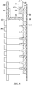
- FIG. 4 which illustrates a cross section of an exemplary electrical panel 300 with an energized parts guard installed
- the energized electrical bus 106 is supported on insulators or an insulative component 400 (such as a molded plastic bracket) to insulate them from the grounded enclosure 114.
- the incoming circuit conductors are typically connected 402 to the bus 106 by clamping with a threaded fastener. The method of clamping depends on the design of the panel and the rated voltage and current of the electrical panel. For most applications the wires 404 of the incoming circuits 100 will be stripped of insulation 406 and the bare conductors will be inserted into a clamp 414 which is tightened by turning a screw. For higher voltages and/or current, a separate terminal may be crimped onto the bare conductor and then bolted to the bus.
- the load circuits are generally connected to the circuit breaker 104 terminals 112 by clamping with a threaded fastener.
- the wires of the outgoing circuits 102 will be stripped of insulation and the bare conductors will be inserted into a clamp which is tightened by turning a screw.
- the clamp is normally integral to the circuit breaker 104.
- a terminal may be crimped onto the bare conductor and then bolted to the circuit breaker 104 or, in the case of "rack-out" breakers, a bus extension.
- circuit breakers 104 snap into place. In these configurations, the circuit breakers 104 are held in place by mating features on the bus 106 and/or the insulator(s) 400 supporting the bus 106. Circuit breakers for higher voltage and current may be bolted into place or they may be inserted or removed via a mechanism, a process referred to as "racking in / racking out.”
- the energized parts guard 408 is made primarily of electrically insulating materials, such as polymers, ceramics, or wood.
- the energized parts guard 408 is preferably made from a substantially-rigid, electrically-insulating polymer.
- the energized parts guard 408 is more preferably made from an impact-resistant, substantially-rigid, electrically-insulating polymer.
- the energized parts guard 408 is most preferably made from a transparent, impact-resistant, substantially-rigid, electrically-insulating polymer.
- the energized parts guard 408 may be made from polycarbonate (PC).
- the parts guard may be made from a material including two or more laminations of polycarbonate.
- the energized parts guard 408 may be made from poly(methyl methacrylate) (PMMA).
- the material of the energized parts guard 408 may be treated or formulated to resist degradation from ultraviolet light.
- the material of the energized parts guard 408 may be treated or formulated to resist electrical tracking. Electrical tracking is the degradation of a polymeric insulating material over time by partial discharges of electricity resulting in deposition of a conductive carbon "track" on the insulating surface.
- the energized parts guard 408 includes a panel 410 with a plurality of apertures (i.e. holes or openings) and one or more covers for the apertures.
- the panel 410 is a sheet of insulating material having sufficient height and width to prevent direct exposure to any conductors exposed by removing the front panel 304 of an electrical panel 300. Any incidental contact with an exposed energized conductor is thus avoided. In the preferred embodiment, the height and width will match the front panel 304 removed from the electrical panel 300.
- the panel 410 of the energized parts guard 408 is sufficiently stiff to prevent excessive flexing from incidental contact. Excessive flexing in this case would permanently deform the panel or allow contact with exposed energized conductors.
- sufficient stiffness may be achieved by a flat panel of sufficient thickness. In another embodiment, sufficient stiffness may be achieved by ribs, walls, or pockets which are molded into, embossed into, fastened to, or otherwise incorporated into the panel.
- the energized parts guard 408 includes one or more circuit-breaker apertures 500, which fit over the insulated controls 306 of the circuit breakers 104 when the energized parts guard 408 is installed on an electrical panel 300.
- the circuit-breaker apertures 500 are so dimensioned that when properly installed, the circuit-breaker apertures 500 allow the insulated controls 306 to protrude through the energized parts guard 408 while preventing inadvertent contact with the energized conductors which were exposed by removing the front panel 304 of the electrical panel 300.
- the exact shape of the circuit-breaker apertures 500 depends on the exact configuration of the electrical panel 300, which is dependent on the electrical panel's manufacturer and model, among other factors. In the preferred embodiment, the circuit-breaker apertures 500 have the same dimensions as the maximum corresponding openings (i.e. with any knockouts 308 removed) as the front panel 304 of the electrical panel 300.
- the energized parts guard 408 also includes a one or more terminal apertures 502.
- the terminal apertures 502 are aligned with terminals 112 of the circuit breakers 104. This allows access, through the terminal apertures 502, to the circuit breaker terminals 112 with a tool. In one embodiment, this allows accessing the circuit-breaker terminals 112 with a screwdriver to clamp or unclamp a circuit conductor.
- the energized parts guard 408 may include a one or more mounting apertures 504.
- the mounting apertures 504 are preferably positioned and dimensioned to match the mounting arrangement of the front panel 304 of the metallic enclosure 114. For example, if the front panel 304 of the metallic enclosure 114 is mounted to 4 posts within the enclosure 114 using 4 screws, the mounting apertures 504 of the energized parts guard 408 would be four holes matching the mounting holes found in the front panel 304 of the enclosure 114.
- FIG. 6 illustrates another embodiment, in which the energized parts guard 408 may include additional insulating partitions.
- the additional partitions 412 are dimensioned so that any loose or disconnected outgoing circuit conductors cannot inadvertently touch an exposed incoming circuit conductor.
- additional partitions 600 are dimensioned so that loose or disconnected circuit conductors cannot inadvertently touch adjacent conductors or conductive materials (e.g. adjacent outgoing circuits, the enclosure, etc.).
- the additional partitions in the second embodiment may separate individual incoming circuits from each other or they may separate individual outgoing circuits from each other.
- the first and second embodiments may be used simultaneously or independently.
- additional partitions may be added when other known factors or situation-specific hazards warrant additional electrical or physical guarding.
- FIG. 7 illustrates the energized parts guard 408 installed on an electrical panel 300.
- one or more circuit breaker positions may be empty 702.
- the energized parts guard 408 is dimensioned so that a lock or tag or lockout/tagout device can be attached to the insulated controls 306 of the one or more circuit breakers 104.
- the energized parts guard 408 includes insulated terminal covers for the terminal apertures 502.
- FIG. 8 illustrates the energized parts guard 408 installed on an electrical panel 300 with the insulated terminal covers 800 and a circuit-breaker blank 804 covering an open circuit-breaker position 702.
- the insulated terminal covers 800 are configured to completely cover each terminal aperture and to stay in place without assistance. When properly installed, the insulated terminal covers 800 prevent access to exposed energized parts.
- the insulated terminal covers 800 may be held in place by friction or by additional features on the energized parts guard 408.
- the insulated terminal covers 800 may be so dimensioned that they snap into terminal apertures 502.
- the insulated terminal covers 800 may resemble grommets made of flexible plastic or an elastomer.
- the insulated terminal covers 800 may also be tethered 802 to the energized parts guard 408 and/or to each other, to prevent losing them.
- the insulated terminal covers 800 and the tethers 802 may be fashioned as a single contiguous piece.
- the insulated terminal covers 800 and the tethers 802 may be molded as a single polymer component.
- the preferred embodiment which matches the opening of the removed front panel 304, also permits using the same circuit-breaker blanks 804 with the energized parts guard 408 as used with the removable front panel 304. Snapping the blank 804 into the energized parts guard 408 over the empty circuit breaker position 700 prevents access to the energized bus 106.
- the insulated terminal covers 800 may be made of rigid plastic and be configured as doors attached to the energized parts guard 408.
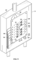
- the door insulated terminal covers 900 may slide back and forth or may swing on a hinge.
- the door insulated terminal covers 900 interlock with the insulated controls 306 of the circuit breakers 104.
- the interlock prevents opening of the door cover unless the insulated control of the circuit breaker 104 is in the open position.
- a sliding door cover may include an additional slot 902 which fits over the control lever of the circuit breaker, preventing the door cover from sliding open when the circuit breaker 104 is closed because it physically interferes with the lever of the circuit breaker.
- a similar interlock may be used on hinged door insulated terminal covers.
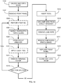
- FIG. 10 illustrates an exemplary method for using the energized parts guard to remove an outgoing circuit from an electrical panel.
- the door is unlocked and opened.
- the front panel is removed.
- any diagnostic testing or troubleshooting is performed on the exposed energized conductors, if needed.
- the energized parts guard is installed over the circuit breaker controls.
- the circuit breaker for the outgoing circuit to be removed is opened, de-energizing the circuit.
- a lock and/or tag is applied to the opened circuit breaker, if required by safety rules.
- the insulating cover over the terminal of the opened circuit breaker is removed, exposing the terminal aperture.
- the exposed terminal is tested to confirm the circuit it de-energized. If not, additional troubleshooting may be required.
- an appropriate tool such as a screwdriver, is inserted through the terminal aperture.
- the wire for the outgoing circuit is disconnected from the circuit breaker using the tool.
- the wire is removed from the circuit breaker. If appropriate, the wire may be pulled back though conduit to its origin, or it may be temporarily capped with a wire nut, or it may be connected to the neutral bus for safety.
- the energized parts guard is removed.
- the front panel is replaced.
- the door is closed and locked.
Landscapes
- Engineering & Computer Science (AREA)
- Power Engineering (AREA)
- Manufacturing & Machinery (AREA)
- Distribution Board (AREA)
- Patch Boards (AREA)
Description
- This disclosure relates to safety devices for electrical maintenance. More specifically, this disclosure relates to a device to prevent contact with exposed energized electrical conductors during electrical maintenance.
- Electrical panels are used to distribute electrical energy within buildings. Depending on the voltage, purpose, and configuration, electrical panels may be described as "load centers," "panelboards," "distribution boards," "switchboards," "switchgear," or by other terms used in the industry and known to those skilled in the art. For the purposes of this disclosure, an electrical panel includes a metallic enclosure, one or more incoming power circuits (feeders or electrical power sources), one or more outgoing power circuits (serving electrical loads), and one or more circuit-switching devices which control the flow of electricity among the circuits.
- Inside the metallic enclosure of the electrical panel, the incoming circuits may be connected to the circuit breakers directly or via an electrical bus. Connection of the incoming circuit via an electrical bus is the most common configuration and will be assumed, without limitation, throughout the remainder of this application. Most applications will include two or three energized ("hot" or "live") buses of different polarities and one or two neutral buses. The energized buses are normally of two or three different phases. Neutral buses are normally bonded to ground potential at the building's electrical service entrance and allowed to electrically "float" above ground potential throughout the rest of the building. In demanding applications, for example above 1000 volts, the electrical panel may also include a separate ground bus.
- The circuit-switching devices are most commonly circuit breakers. Therefore reference to "circuit breakers" throughout this application includes, without limitation, other circuit-switching devices, including switches, fuses, and switch-fuse combinations. The circuit breakers have controls which are electrically insulated from the incoming and outgoing power circuits. Each load circuit is connected to the bus through a circuit breaker. The circuit breakers allow the load circuits to be manually de-energized using the insulated control of the circuit breaker. The circuit breaker also automatically de-energizes the circuit in response to an overload or short circuit. Depending on the application, a main circuit breaker (not shown) may be provided to isolate the buses from the incoming circuits. A main circuit breaker will often be required by code when the number of load circuits exceeds a certain number.
-
FIG. 1 illustrates the circuit diagram of an exemplary electrical panel. In this example, the electrical panel has two incoming circuits 100 (two-phase) and twelveoutgoing circuits 102. Eachoutgoing circuit 102 is connected to acircuit breaker 104. Eachcircuit breaker 104 is connected in turn to anenergized bus 106. In this example, theneutral bus 108 is bonded 110 to ground. Theenergized buses 106,neutral bus 108, andcircuit breakers 104 are all contained within a groundedmetallic enclosure 114.FIG. 2 illustrates the circuit diagram for a similar exemplary electrical panel, in this case having three incoming circuits (three-phase). -
FIG. 3 illustrates the exterior of anelectrical panel 300. Themetallic enclosure 114 is electrically grounded. Themetallic enclosure 114 normally includes alockable door 302 and aremovable front panel 304. When locked, thedoor 302 prevents unauthorized access to theinsulated controls 306 of thecircuit breakers 104. When locked, cover also prevents removal of thefront panel 304. Thefront panel 304 is held in place by threadedfasteners 310. - The
insulated controls 306 of thecircuit breakers 104 extend through at least one wall of themetallic enclosure 114, normally thefront panel 304. This allows a user to operate the circuit breaker(s) without exposure to any energized parts within themetallic enclosure 114. Common types ofinsulated controls 306 include switches, levers, and push-buttons, although other types of controls may be used. In some configurations theremovable front panel 304 may have permanentlyremovable sections 308 to accommodate addingcircuit breakers 104 to theelectrical panel 300. Theseremovable sections 308 are called "knockouts" because they are removed by breaking a weld or a perforation in the metallic panel, usually with a hammer, screwdriver, and pliers. If aknockout 308 is removed and no corresponding circuit breaker is added to the electrical panel, the energized bus will be exposed in the empty breaker position. Special inserts, called "blanks," are available which snap into the front panel and prevent the energized bus from being exposed. - The International Electrotechnical Commission (IEC) publishes standards for controlling access to electrical equipment. These Ingress Protection (IP) standards consist of a two-digit number. The first digit defines the protection against the ingress of solid objects. The second digit defines the protection against the ingress of liquids. For example, an IP31 enclosure provides protection against the ingress of solid objects 2.5 mm in diameter and against water dripping from above. In the United States, the National Electrical Manufacturer's Association (NEMA) produces a similar standard for ingress protection. The IP ratings are summarized in the table below:
Table 1 Solid Object Protection Liquid Protection Level Object size protected against Effective against Level Object size protected against 0 Not protected No protection against contact and ingress of objects 0 Not protected 1 >50mm Any large surface of the body, such as the back of the hand, but no protection against deliberate contact with a body part. 1 Dripping water 2 >12.5mm Fingers or similar objects. 2 Dripping water when tilted up to 15° 3 >2.5mm Tools, thick wires, etc. 3 Spraying water 4 >1mm Most wires, screws, etc. 4 Splashing water 5 Dust Protected Ingress of dust is not entirely prevented, but it must not enter in sufficient quantity to interfere with the satisfactory operation of the equipment; complete protection against contact. 5 Water jets 6 Dust Tight No ingress of dust; complete protection against contact. 6 Powerful water jets 7 Immersion up to 1m 8 Immersion beyond 1m - When working on the circuits in the
electrical panel 300, thefront panel 304 of themetallic enclosure 114 must be removed to expose the clamped and/or bolted connections of each circuit to the bus or circuit breakers. This work may include, but is not limited to: testing whether a circuit is energized, troubleshooting a circuit, adding a circuit, removing a circuit, upgrading a circuit, moving a circuit to a different circuit breaker, replacing a faulty circuit breaker, and upgrading a circuit breaker. In short, any work involving testing, moving acircuit breaker 104, or moving a wire will likely require removing thefront panel 304 of themetallic enclosure 114. - If any of the incoming circuits are energized, removing the front panel will expose the worker to energized parts. Exposure to energized parts creates a hazard of electrocution and a hazard of an arc flash. An arc flash occurs when electricity "jumps" through the air from an energized conductor to a grounded conductor or a conductor of a different polarity. Air is normally an insulator, so the electricity must ionize the air, releasing light and heat. In some cases, the energy released is enough to create an explosive pressure wave and eject electrical components and molten metal. While the risk of electrocution is based primarily on the nominal system voltage, the hazard from an arc flash is based on both the system voltage and the short-circuit current. Unlike voltage, available short-circuit current must be determined on a panel-by-panel basis by an engineering study, making it much more difficult to classify the arc-flash hazard.
- In the past, work safety practices focused only on reducing the risk of electrocution. Workers could work on energized parts if they used appropriate Personal Protective Equipment (PPE). For example, work on energized parts required special electrically insulated tools and/or specially-rated electrically insulated gloves. Rules may also have required hard hats or boots specially rated for their electrically insulating properties.
- Another work safety practice is called "lockout/tagout." This practice is intended to prevent accidents from working on an energized circuit in the mistaken belief that the circuit is de-energized. When a circuit breaker is opened, de-energizing the circuit, lockout/tagout requires attaching a lock and/or tag to the insulated control of the circuit breaker. The lock and/or tag prevents accidentally closing the circuit breaker and energizing the circuit, which could endanger an unsuspecting person working elsewhere on that circuit. In many circumstances additional devices may be temporarily fitted to the insulated control of the circuit breaker to accommodate the lock or tag.
- As industry awareness of the arc-flash hazard grew, the Occupational Health and Safety Administration (OSHA), a federal agency governing workplace safety, created new rules to reduce the risk of arc-flash injuries. The new rules required that "[1]ive parts [above 50 volts] to which an employee may be exposed shall be de-energized before the employee works on or near them, unless the employer can demonstrate that de-energizing introduces additional or increased hazards or is infeasible due to equipment design or operational limitations." 29 CFR 1910.333(a)(1). The old practice of working on or near exposed energized circuits, even with appropriate PPE, is thus prohibited unless the employer proves that de-energizing all of the circuits increases hazards or is "infeasible".
- Energized work is allowed to avoid introducing "additional or increased hazards" only when life-safety equipment is de-energized. For example, circuits supplying fire alarms, sprinkler pumps, and life-support equipment may be worked-on while energized. This limitation is strictly enforced.
- Testing and troubleshooting de-energized circuits is considered "infeasible" because electrical power is needed to check an electrical circuit's function. Therefore, testing of energized circuits is allowed, but no other work may be done on or near them. The use of "tools" (i.e. metallic tools which are likely to cause a flash-over, even if they insulate the user from electrocution) is specifically prohibited.
EP2650988 discusses a protection cover which has a cover portion whose ends are provided with locking devices containing detent which is movable between opening position and check position. The detent is moved into opening position with a tool, so as to remove contact protection cover from a carrier in the switchgear cabinet.US5301086 discusses a terminal barrier for use in an electrical distribution load center having a housing defined by side walls upstanding from a back wall. The barrier is positioned to separate the input terminals from the output terminals and includes interlocking elements for disengagingly connecting one end of the barrier to the side wall of the housing.DE8201036 discusses a contact protection cover in electrical distribution boards with electrical, in-line built-in devices. - According to one aspect, a system comprising an electrical panel and an energized parts guard is disclosed as set out in
claim 1. -
-
Fig. 1 is a circuit diagram of a two-phase electrical panel illustrating the incoming circuits, outgoing circuits, buses, and circuit breakers, in accordance with the present disclosure. -
Fig. 2 is a circuit diagram of a three-phase electrical panel illustrating the incoming circuits, outgoing circuits, buses, and circuit breakers, in accordance with the present disclosure. -
Fig. 3 is an isometric drawing of the exterior of an electrical panel illustrating the metallic enclosure, the lockable front door, and the removable front panel in accordance with the present disclosure. -
Fig. 4 is a cross-section of an electrical panel with the energized parts guard installed, illustrating the enclosure, the bus, an incoming circuit, the circuit breakers, and the energized parts guard in accordance with the present disclosure. -
Fig. 5 is an isometric drawing of the energized parts guard illustrating its basic features in accordance with the present disclosure. -
Fig. 6 is an isometric drawing of the energized parts guard with the addition of an intervening barriers illustrating the features of both in accordance with the present disclosure. -
Fig. 7 is an isometric drawing of the energized parts guard installed in an electrical panel, without the covers on the terminal apertures, illustrating the relationship between the energized parts guard and the enclosure and circuit breakers of the electrical panel in accordance with the present disclosure. -
Fig. 8 is an isometric drawing of the energized parts guard installed in an electrical panel, with the covers on the terminal apertures and a circuit-breaker blank covering an open circuit-breaker position, illustrating the relationship between the energized parts guard and the enclosure and circuit breakers of the electrical panel in accordance with the present disclosure. -
Fig. 9A an isometric drawing of one embodiment the energized parts guard illustrating a sliding door cover obstructing the terminal aperture and interlocking with the closed circuit breaker in accordance with the present disclosure. -
Fig. 9B an isometric drawing of one embodiment the energized parts guard illustrating a sliding door cover exposing the terminal aperture and interlocking with the open circuit breaker in accordance with the present disclosure. -
Fig. 10 is a flow chart of one exemplary method of using the energized parts guard in accordance with the present disclosure. - An energized parts guard is disclosed to permit working in the vicinity of energized circuits without exposing an operator to the exposed energized components. The energized parts guard is insulative. When properly used, the energized parts guard prevents contact with any exposed energized parts within an electrical panel but allows access to de-energized components to work on them.
- To facilitate an understanding of the principals and features of the disclosed technology, illustrative embodiments are explained below. The components described hereinafter as making up various elements of the disclosed technology are intended to be illustrative and not restrictive. Many suitable components that would perform the same or similar functions as components described herein are intended to be embraced within the scope of the disclosed electronic devices and methods. Such other components not described herein may include, but are not limited to, for example, components developed after development of the disclosed technology.
- It must also be noted that, as used in the specification and the appended claims, the singular forms "a," "an" and "the" include plural referents unless the context clearly dictates otherwise.
- By "comprising" or "containing" or "including" is meant that at least the named compound, element, particle, or method step is present in the composition or article or method, but does not exclude the presence of other compounds, materials, particles, method steps, even if the other such compounds, material, particles, method steps have the same function as what is named.
- It is also to be understood that the mention of one or more method steps does not preclude the presence of additional method steps or intervening method steps between those steps expressly identified. Similarly, it is also to be understood that the mention of one or more components in a device or system does not preclude the presence of additional components or intervening components between those components expressly identified.
- Referring now to
FIG. 4 , which illustrates a cross section of an exemplaryelectrical panel 300 with an energized parts guard installed, the energizedelectrical bus 106 is supported on insulators or an insulative component 400 (such as a molded plastic bracket) to insulate them from the groundedenclosure 114. The incoming circuit conductors are typically connected 402 to thebus 106 by clamping with a threaded fastener. The method of clamping depends on the design of the panel and the rated voltage and current of the electrical panel. For most applications thewires 404 of theincoming circuits 100 will be stripped ofinsulation 406 and the bare conductors will be inserted into aclamp 414 which is tightened by turning a screw. For higher voltages and/or current, a separate terminal may be crimped onto the bare conductor and then bolted to the bus. - The load circuits are generally connected to the
circuit breaker 104terminals 112 by clamping with a threaded fastener. In most applications, the wires of theoutgoing circuits 102 will be stripped of insulation and the bare conductors will be inserted into a clamp which is tightened by turning a screw. For load circuits, the clamp is normally integral to thecircuit breaker 104. For higher voltages and/or current, a terminal may be crimped onto the bare conductor and then bolted to thecircuit breaker 104 or, in the case of "rack-out" breakers, a bus extension. - In many configurations the
circuit breakers 104 snap into place. In these configurations, thecircuit breakers 104 are held in place by mating features on thebus 106 and/or the insulator(s) 400 supporting thebus 106. Circuit breakers for higher voltage and current may be bolted into place or they may be inserted or removed via a mechanism, a process referred to as "racking in / racking out." - The energized parts guard 408 is made primarily of electrically insulating materials, such as polymers, ceramics, or wood. The energized parts guard 408 is preferably made from a substantially-rigid, electrically-insulating polymer. The energized parts guard 408 is more preferably made from an impact-resistant, substantially-rigid, electrically-insulating polymer. The energized parts guard 408 is most preferably made from a transparent, impact-resistant, substantially-rigid, electrically-insulating polymer. In one embodiment, the energized parts guard 408 may be made from polycarbonate (PC). In another embodiment, the parts guard may be made from a material including two or more laminations of polycarbonate. In another embodiment, the energized parts guard 408 may be made from poly(methyl methacrylate) (PMMA). In another embodiment, the material of the energized parts guard 408 may be treated or formulated to resist degradation from ultraviolet light. In another embodiment, the material of the energized parts guard 408 may be treated or formulated to resist electrical tracking. Electrical tracking is the degradation of a polymeric insulating material over time by partial discharges of electricity resulting in deposition of a conductive carbon "track" on the insulating surface.
- The energized parts guard 408 includes a
panel 410 with a plurality of apertures (i.e. holes or openings) and one or more covers for the apertures. Thepanel 410 is a sheet of insulating material having sufficient height and width to prevent direct exposure to any conductors exposed by removing thefront panel 304 of anelectrical panel 300. Any incidental contact with an exposed energized conductor is thus avoided. In the preferred embodiment, the height and width will match thefront panel 304 removed from theelectrical panel 300. - The
panel 410 of the energized parts guard 408 is sufficiently stiff to prevent excessive flexing from incidental contact. Excessive flexing in this case would permanently deform the panel or allow contact with exposed energized conductors. In one embodiment, sufficient stiffness may be achieved by a flat panel of sufficient thickness. In another embodiment, sufficient stiffness may be achieved by ribs, walls, or pockets which are molded into, embossed into, fastened to, or otherwise incorporated into the panel. - Referring now to
FIG. 5 , which illustrates the basic features of the energized parts guard, the energized parts guard 408 includes one or more circuit-breaker apertures 500, which fit over theinsulated controls 306 of thecircuit breakers 104 when the energized parts guard 408 is installed on anelectrical panel 300. The circuit-breaker apertures 500 are so dimensioned that when properly installed, the circuit-breaker apertures 500 allow theinsulated controls 306 to protrude through the energized parts guard 408 while preventing inadvertent contact with the energized conductors which were exposed by removing thefront panel 304 of theelectrical panel 300. The exact shape of the circuit-breaker apertures 500 depends on the exact configuration of theelectrical panel 300, which is dependent on the electrical panel's manufacturer and model, among other factors. In the preferred embodiment, the circuit-breaker apertures 500 have the same dimensions as the maximum corresponding openings (i.e. with anyknockouts 308 removed) as thefront panel 304 of theelectrical panel 300. - The energized parts guard 408 also includes a one or more
terminal apertures 502. When the energized parts guard 408 is installed on anelectrical panel 300 theterminal apertures 502 are aligned withterminals 112 of thecircuit breakers 104. This allows access, through theterminal apertures 502, to thecircuit breaker terminals 112 with a tool. In one embodiment, this allows accessing the circuit-breaker terminals 112 with a screwdriver to clamp or unclamp a circuit conductor. - In some embodiments the energized parts guard 408 may include a one or more mounting
apertures 504. The mountingapertures 504 are preferably positioned and dimensioned to match the mounting arrangement of thefront panel 304 of themetallic enclosure 114. For example, if thefront panel 304 of themetallic enclosure 114 is mounted to 4 posts within theenclosure 114 using 4 screws, the mountingapertures 504 of the energized parts guard 408 would be four holes matching the mounting holes found in thefront panel 304 of theenclosure 114. -
FIG. 6 illustrates another embodiment, in which the energized parts guard 408 may include additional insulating partitions. In a first embodiment, theadditional partitions 412 are dimensioned so that any loose or disconnected outgoing circuit conductors cannot inadvertently touch an exposed incoming circuit conductor. In a second embodiment,additional partitions 600 are dimensioned so that loose or disconnected circuit conductors cannot inadvertently touch adjacent conductors or conductive materials (e.g. adjacent outgoing circuits, the enclosure, etc.). For example, the additional partitions in the second embodiment may separate individual incoming circuits from each other or they may separate individual outgoing circuits from each other. The first and second embodiments may be used simultaneously or independently. In further embodiments, additional partitions may be added when other known factors or situation-specific hazards warrant additional electrical or physical guarding. -
FIG. 7 illustrates the energized parts guard 408 installed on anelectrical panel 300. In some cases one or more circuit breaker positions may be empty 702. In some embodiments, the energized parts guard 408 is dimensioned so that a lock or tag or lockout/tagout device can be attached to theinsulated controls 306 of the one ormore circuit breakers 104. - The energized parts guard 408 includes insulated terminal covers for the
terminal apertures 502.FIG. 8 illustrates the energized parts guard 408 installed on anelectrical panel 300 with the insulated terminal covers 800 and a circuit-breaker blank 804 covering an open circuit-breaker position 702. The insulated terminal covers 800 are configured to completely cover each terminal aperture and to stay in place without assistance. When properly installed, the insulated terminal covers 800 prevent access to exposed energized parts. The insulated terminal covers 800 may be held in place by friction or by additional features on the energized parts guard 408. For example, in one embodiment the insulated terminal covers 800 may be so dimensioned that they snap intoterminal apertures 502. In this embodiment, the insulated terminal covers 800 may resemble grommets made of flexible plastic or an elastomer. In this embodiment, the insulated terminal covers 800 may also be tethered 802 to the energized parts guard 408 and/or to each other, to prevent losing them. In another embodiment, the insulated terminal covers 800 and thetethers 802 may be fashioned as a single contiguous piece. For example , the insulated terminal covers 800 and thetethers 802 may be molded as a single polymer component. - The preferred embodiment, which matches the opening of the removed
front panel 304, also permits using the same circuit-breaker blanks 804 with the energized parts guard 408 as used with the removablefront panel 304. Snapping the blank 804 into the energized parts guard 408 over the emptycircuit breaker position 700 prevents access to the energizedbus 106. - In another embodiment, the insulated terminal covers 800 may be made of rigid plastic and be configured as doors attached to the energized parts guard 408. In this embodiment, the door insulated terminal covers 900 may slide back and forth or may swing on a hinge.
- According to the invention, illustrated in
FIGS. 9A and 9B , the door insulated terminal covers 900 interlock with theinsulated controls 306 of thecircuit breakers 104. The interlock prevents opening of the door cover unless the insulated control of thecircuit breaker 104 is in the open position. For example, a sliding door cover may include anadditional slot 902 which fits over the control lever of the circuit breaker, preventing the door cover from sliding open when thecircuit breaker 104 is closed because it physically interferes with the lever of the circuit breaker. A similar interlock may be used on hinged door insulated terminal covers. -
FIG. 10 illustrates an exemplary method for using the energized parts guard to remove an outgoing circuit from an electrical panel. At 1000, the door is unlocked and opened. At 1002 the front panel is removed. At 1004, any diagnostic testing or troubleshooting is performed on the exposed energized conductors, if needed. At 1006, the energized parts guard is installed over the circuit breaker controls. At 1008, the circuit breaker for the outgoing circuit to be removed is opened, de-energizing the circuit. At 1010, a lock and/or tag is applied to the opened circuit breaker, if required by safety rules. At 1012, the insulating cover over the terminal of the opened circuit breaker is removed, exposing the terminal aperture. At 1014, the exposed terminal is tested to confirm the circuit it de-energized. If not, additional troubleshooting may be required. At 1016, an appropriate tool, such as a screwdriver, is inserted through the terminal aperture. At 1018, the wire for the outgoing circuit is disconnected from the circuit breaker using the tool. At 1020, the wire is removed from the circuit breaker. If appropriate, the wire may be pulled back though conduit to its origin, or it may be temporarily capped with a wire nut, or it may be connected to the neutral bus for safety. At 1022, the energized parts guard is removed. At 1024, the front panel is replaced. At 1026, the door is closed and locked. - The design and functionality described in this application is intended to be exemplary in nature and is not intended to limit the instant disclosure in any way. Those having ordinary skill in the art will appreciate that the teachings of the disclosure may be implemented in a variety of suitable forms, including those forms disclosed herein and additional forms known to those having ordinary skill in the art.
- While certain embodiments of this disclosure have been described in connection with what is presently considered to be the most practical and various embodiments, it is to be understood that this disclosure is not to be limited to the disclosed embodiments, but on the contrary, is intended to cover various modifications and equivalent arrangements included within the scope of the appended claims. Although specific terms are employed herein, they are used in a generic and descriptive sense only and not for purposes of limitation.
- This written description uses examples to disclose certain embodiments of the technology and also to enable any person skilled in the art to practice certain embodiments of this technology, including making and using any apparatuses or systems and performing any incorporated methods. The patentable scope of certain embodiments of the technology is defined in the claims, and may include other examples that occur to those skilled in the art. Such other examples are intended to be within the scope of the claims if they have structural elements that do not differ from the literal language of the claims, or if they include equivalent structural elements with insubstantial differences from the literal language of the claims.
Claims (13)
- A system comprising:an electrical panel (300) comprising an enclosure (114) enclosing one or more circuit breakers (104); andan energized parts guard (408) configured to be installed on the electrical panel (300) and comprising a panel (410) of substantially rigid, electrically insulative material wherein the substantially rigid panel (410) further comprises a first one or more apertures (500);wherein the first one or more apertures (500) are so dimensioned to accept the one or more circuit breakers (104) inserted into the first one or more apertures (500) when the energized parts guard (408) is installed on the electrical panel (300) such that there is less than a 12.5 mm gap between the panel (410) and the circuit breaker (104) on at least two sides of the one or more circuit breakers (104);characterised by:the substantially rigid panel (410) further comprising a second one or more apertures (502);and in that:the energized parts guard (408) further comprises electrically insulating covers (900) for the second one or more apertures (502);the second one or more apertures (502) are aligned with at least one terminal (112) of the one or more circuit breakers (104) when the energized parts guard (408) is installed on the electrical panel (300) and when the one or more circuit breakers are inserted into the first one or more apertures (500) to facilitate access to the at least one terminal (112); andthe insulating covers (900) interlock with the one or more circuit breakers (104), preventing access to the circuit-breaker terminals (112) unless the circuit breakers (104) are in the open position.
- The system of claim 1, wherein the energized parts guard (408) further comprises a third one or more apertures (504) configured to facilitate mounting the energized parts guard (408) to the electrical panel (300) when the one or more circuit breakers (104) are inserted into the first one or more apertures (500).
- The system of claim 1 wherein the first one or more apertures (500) are further configured such that there is less than 12.5 mm gap between the panel (410) and the one or more circuit breakers (104) on at least three sides of the one or more circuit breakers (104).
- The system of claim 3 wherein the first one or more apertures (500) are further configured such that there is less than 12.5 mm gap between the panel (410) and the one or more circuit breakers (104) on at least four sides of the one or more circuit breakers (104).
- The system of claim 1 wherein there is less than a 2.5 mm gap between the panel (410) and the one or more circuit breakers (104) on at least two sides of the one or more circuit breakers (104).
- The system of claim 1 wherein the panel (410) of substantially rigid, electrically insulative material extends at least 50 mm beyond any exposed edge of any of the one or more circuit breakers (104) inserted into the first one or more apertures (500).
- The system of claim 1 wherein the panel (410) of substantially rigid, electrically insulative material extends at least 50 mm from any terminal of the one or more circuit breakers (104) inserted into the first one or more apertures (500).
- The system of claim 1 wherein all of the outer edges of the panel (410) of substantially rigid, electrically insulative material are so dimensioned that each is no greater than 50 mm from the metallic enclosure (114) housing the one or more circuit breakers (104) when the one or more circuit breakers (104) are inserted into the first one or more apertures (500).
- The system of claim 1 wherein the edges of the panel (410) of substantially rigid, electrically insulative material are configured to prevent contact with:any terminals (112) of any circuit breakers (104) inserted into the first one or more apertures (500), except through the second one or more apertures (502);any electrical bus (106) connected to any circuit breakers (104) inserted into the first one or more apertures (500);any exposed electrical conductors (402) connected to the circuit breakers (104) inserted into the first one or more apertures (500) or connected to the electrical bus (106) connected to any circuit breakers (104) inserted into the first one or more apertures (500).
- The system of claim 1 wherein the insulating covers (800) are tethered to the energized parts guard (408).
- The system of claim 1 wherein the electrically insulating covers (800) are tethered to one another.
- The system of claim 11 wherein the tethers (802) between the electrically insulating covers (800) of the plurality of electrically insulating covers (800) are contiguous with the electrically insulating covers (800) they tether.
- The system of claim 1 wherein the energized parts guard (408) is so dimensioned to permit attaching a lock or tag to an insulated control of at least one of the one or more circuit breakers (104) when the one or more circuit breakers (104) are inserted into the first one or more apertures (500).
Applications Claiming Priority (2)
| Application Number | Priority Date | Filing Date | Title |
|---|---|---|---|
| US14/567,832 US9530582B2 (en) | 2014-12-11 | 2014-12-11 | Energized parts guard |
| PCT/US2015/064882 WO2016094605A1 (en) | 2014-12-11 | 2015-12-10 | Energized parts guard |
Publications (3)
| Publication Number | Publication Date |
|---|---|
| EP3230996A1 EP3230996A1 (en) | 2017-10-18 |
| EP3230996A4 EP3230996A4 (en) | 2018-08-29 |
| EP3230996B1 true EP3230996B1 (en) | 2020-07-01 |
Family
ID=56108152
Family Applications (1)
| Application Number | Title | Priority Date | Filing Date |
|---|---|---|---|
| EP15866681.8A Active EP3230996B1 (en) | 2014-12-11 | 2015-12-10 | System comprising an electrical panel and an energized parts guard |
Country Status (5)
| Country | Link |
|---|---|
| US (5) | US9530582B2 (en) |
| EP (1) | EP3230996B1 (en) |
| CA (1) | CA2972442C (en) |
| MX (1) | MX373701B (en) |
| WO (1) | WO2016094605A1 (en) |
Families Citing this family (3)
| Publication number | Priority date | Publication date | Assignee | Title |
|---|---|---|---|---|
| US10236665B2 (en) * | 2016-11-14 | 2019-03-19 | Infratech Corporation | Insulated electrical switch cabinet cover |
| TWI610507B (en) * | 2017-06-08 | 2018-01-01 | Programmable AC power distributor | |
| USD1037801S1 (en) * | 2021-06-14 | 2024-08-06 | Norman R. Byrne | Housing for electrical junction |
Family Cites Families (37)
| Publication number | Priority date | Publication date | Assignee | Title |
|---|---|---|---|---|
| US3375411A (en) | 1967-07-03 | 1968-03-26 | Gen Electric | Electrical circuit control device panel board with novel insulating means |
| US3590332A (en) * | 1969-03-20 | 1971-06-29 | Westinghouse Canada Ltd | Panelboard with insulative circuit breaker supports mounted on the bus bars |
| US3618804A (en) * | 1969-10-20 | 1971-11-09 | Gen Electric | Concealed trim clamp for electrical panelboards and other wiring cabinets |
| US3656083A (en) | 1970-09-01 | 1972-04-11 | Richard G Brook | Electrical safety device |
| DE8201036U1 (en) * | 1982-01-19 | 1982-05-06 | Boensch, Peter, 5820 Gevelsberg | TOUCH PROTECTIVE COVER IN ELECTRICAL INSTALLATION DISTRIBUTORS |
| US4472761A (en) * | 1982-06-18 | 1984-09-18 | Eaton Corporation | Segmented electrical panelboard for industrial frame and residential frame circuit breakers which accepts residential frame circuit breakers at any segment |
| US4642733A (en) * | 1985-04-25 | 1987-02-10 | Schacht Ezra L | Loadcenter "plug-in" surge protector |
| US5072071A (en) * | 1989-07-19 | 1991-12-10 | Square D Company | Wire clamp assembly for an electrical load center |
| US5081560A (en) * | 1990-09-27 | 1992-01-14 | Siemens Energy & Automation, Inc. | Load center enclosure |
| CA2064639C (en) * | 1992-04-01 | 1995-04-18 | Michael Ray Harris | Terminal barrier for electrical load centers |
| US5343356A (en) * | 1992-12-31 | 1994-08-30 | Siemens Energy & Automation, Inc. | Panelboard |
| US5886868A (en) * | 1996-10-10 | 1999-03-23 | Eaton Corporation | Electrical distribution panel enclosure |
| US5894404A (en) | 1997-05-28 | 1999-04-13 | General Electric Company | Circuit breaker panelboard enclosure |
| US6245998B1 (en) | 1999-10-27 | 2001-06-12 | Avaya Technology Corp. | Cable management assembly for equipment racks |
| US6307456B1 (en) * | 1999-12-10 | 2001-10-23 | General Electric Company | Light industrial circuit breaker terminal cover |
| US6313980B1 (en) * | 2000-04-13 | 2001-11-06 | General Electric Company | Trim plate for panelboards and switchboards |
| US6881898B2 (en) * | 2001-03-02 | 2005-04-19 | Liebert Corporation | Remote distribution cabinet |
| US7116550B2 (en) | 2003-10-30 | 2006-10-03 | Server Technology, Inc. | Electrical circuit apparatus with fuse access section |
| US7428131B2 (en) | 2005-02-08 | 2008-09-23 | Gary Guard, Inc. | Safety shield for use with different diameter racking rods and an adaptor for use therewith |
| WO2006119450A2 (en) | 2005-05-04 | 2006-11-09 | Golden Technology Management, Llc | Improved circuit breaker panel |
| US7440262B2 (en) | 2006-12-06 | 2008-10-21 | Adc Telecommunications, Inc. | Modular power distribution system and methods |
| US7686914B2 (en) | 2007-02-12 | 2010-03-30 | Mb Wellington Studio, Inc. | Decorative laminated plastic/metal panels |
| US7688573B2 (en) * | 2008-08-21 | 2010-03-30 | Eaton Corporation | Enclosure and cover assembly therefor |
| US20100096962A1 (en) * | 2008-10-20 | 2010-04-22 | Siemens Energy & Automation, Inc. | Electrical Insulation Barriers Having Knock Out Features |
| US8027154B2 (en) * | 2008-12-31 | 2011-09-27 | General Electric Company | Replacement panel board and methods for selecting |
| US8134828B2 (en) * | 2010-01-21 | 2012-03-13 | Cooper Technologies Company | Configurable deadfront fusible panelboard |
| CA2737815C (en) * | 2010-04-21 | 2016-06-28 | Christopher A. Weighell | Electrical distribution panel |
| US8305739B2 (en) * | 2010-06-10 | 2012-11-06 | Schneider Electric USA, Inc. | High density power/lighting panelboard |
| US20120067610A1 (en) | 2010-09-20 | 2012-03-22 | Stonebraker Michael T | Electrical safety cover |
| US20120186847A1 (en) | 2011-01-21 | 2012-07-26 | Paul Martin | Shield for inspecting electrical panels |
| BRPI1101495B1 (en) | 2011-04-15 | 2020-09-24 | Siemens Aktiengesellschaft | Three-phase or single-phase dry distribution transformer and electrical isolation method for a tap panel of a three-phase or single-phase dry distribution transformer |
| DE102012103251B4 (en) * | 2012-04-14 | 2026-02-12 | Greiner Schaltanlagen Gmbh | Low-voltage or medium-voltage switchgear with a touch protection cover |
| JP6063724B2 (en) | 2012-11-30 | 2017-01-18 | 矢崎総業株式会社 | Electrical junction box |
| US9325158B2 (en) * | 2014-03-13 | 2016-04-26 | General Electric Company | Electrical enclosure including an integrated dead front and door |
| US9748743B2 (en) * | 2015-04-23 | 2017-08-29 | Siemens Industry, Inc. | Electrical panelboard assemblies and methods |
| US9716372B2 (en) * | 2015-06-18 | 2017-07-25 | Eaton Corporation | Switchboard for power distribution system |
| US10374397B2 (en) * | 2016-06-08 | 2019-08-06 | Warren Stanley King, JR. | Non-conductive shield for distribution boards |
-
2014
- 2014-12-11 US US14/567,832 patent/US9530582B2/en active Active
-
2015
- 2015-12-10 MX MX2017007594A patent/MX373701B/en active IP Right Grant
- 2015-12-10 WO PCT/US2015/064882 patent/WO2016094605A1/en not_active Ceased
- 2015-12-10 CA CA2972442A patent/CA2972442C/en active Active
- 2015-12-10 EP EP15866681.8A patent/EP3230996B1/en active Active
-
2016
- 2016-11-17 US US15/354,650 patent/US9893499B2/en active Active
-
2018
- 2018-02-12 US US15/894,296 patent/US10056739B2/en active Active
- 2018-08-20 US US16/105,655 patent/US10707655B2/en active Active
-
2020
- 2020-04-06 US US16/841,164 patent/US11637413B2/en active Active
Non-Patent Citations (1)
| Title |
|---|
| None * |
Also Published As
| Publication number | Publication date |
|---|---|
| EP3230996A4 (en) | 2018-08-29 |
| EP3230996A1 (en) | 2017-10-18 |
| MX2017007594A (en) | 2018-03-09 |
| US20170070035A1 (en) | 2017-03-09 |
| US11637413B2 (en) | 2023-04-25 |
| US9530582B2 (en) | 2016-12-27 |
| US20200235553A1 (en) | 2020-07-23 |
| CA2972442C (en) | 2022-08-09 |
| US9893499B2 (en) | 2018-02-13 |
| CA2972442A1 (en) | 2016-06-16 |
| WO2016094605A1 (en) | 2016-06-16 |
| MX373701B (en) | 2020-05-07 |
| US10707655B2 (en) | 2020-07-07 |
| US20180166864A1 (en) | 2018-06-14 |
| US10056739B2 (en) | 2018-08-21 |
| US20180358787A1 (en) | 2018-12-13 |
| US20160172128A1 (en) | 2016-06-16 |
Similar Documents
| Publication | Publication Date | Title |
|---|---|---|
| US8134828B2 (en) | Configurable deadfront fusible panelboard | |
| US11637413B2 (en) | Methods for making an energized parts guard system | |
| US9716372B2 (en) | Switchboard for power distribution system | |
| US9667051B2 (en) | Power terminal enclosure for power conductors | |
| US10236665B2 (en) | Insulated electrical switch cabinet cover | |
| EP3163694B1 (en) | Electrically insulating cover for terminal assembly | |
| CN109673130B (en) | Electrical unit with improved ventilation protection for a motor control center | |
| WO1992002979A1 (en) | Voltage surge suppression device | |
| US5936199A (en) | Insulating covers for an electrical outlet box | |
| US11710612B2 (en) | Molded case circuit breaker with terminal cover having emboss guides for cable box cover alignment and fixing | |
| US20120033351A1 (en) | Motor control center and bus assembly therefor | |
| US10297985B2 (en) | Modular electrical devices and methods for assembling and mounting the same | |
| US12224561B1 (en) | Compartmentalized panel | |
| EP2557643A1 (en) | Motor control center and bus assembly therefor | |
| DE102007016658A1 (en) | Electrical distributing system, has screen element protecting connections of multi-phase switch components against blowing out gas of connection-lateral multi-phase switch component, and including edge region | |
| GB2500739A (en) | Isolation and distribution box for railway signalling allowing part shutdown for live working | |
| DE202025106656U1 (en) | Electrical system with fuse base and temperature sensor(s) | |
| Wilkie | Comparison of ANSI/IEEE and IEC requirements for low-voltage switchgear | |
| WO2018134641A1 (en) | A sealed enclosure for housing replaceable electrical and electronic components | |
| Gumhalter | Protective Measures | |
| KR20170090634A (en) | Power Distributing Board with a Partition for partitioning a space therein |
Legal Events
| Date | Code | Title | Description |
|---|---|---|---|
| STAA | Information on the status of an ep patent application or granted ep patent |
Free format text: STATUS: THE INTERNATIONAL PUBLICATION HAS BEEN MADE |
|
| PUAI | Public reference made under article 153(3) epc to a published international application that has entered the european phase |
Free format text: ORIGINAL CODE: 0009012 |
|
| STAA | Information on the status of an ep patent application or granted ep patent |
Free format text: STATUS: REQUEST FOR EXAMINATION WAS MADE |
|
| 17P | Request for examination filed |
Effective date: 20170710 |
|
| AK | Designated contracting states |
Kind code of ref document: A1 Designated state(s): AL AT BE BG CH CY CZ DE DK EE ES FI FR GB GR HR HU IE IS IT LI LT LU LV MC MK MT NL NO PL PT RO RS SE SI SK SM TR |
|
| AX | Request for extension of the european patent |
Extension state: BA ME |
|
| DAV | Request for validation of the european patent (deleted) | ||
| DAX | Request for extension of the european patent (deleted) | ||
| REG | Reference to a national code |
Ref country code: DE Ref legal event code: R079 Ref document number: 602015055240 Country of ref document: DE Free format text: PREVIOUS MAIN CLASS: H01H0009020000 Ipc: H02B0001140000 |
|
| A4 | Supplementary search report drawn up and despatched |
Effective date: 20180727 |
|
| RIC1 | Information provided on ipc code assigned before grant |
Ipc: H02B 1/14 20060101AFI20180723BHEP Ipc: H02B 1/06 20060101ALI20180723BHEP Ipc: H02B 3/00 20060101ALI20180723BHEP |
|
| STAA | Information on the status of an ep patent application or granted ep patent |
Free format text: STATUS: EXAMINATION IS IN PROGRESS |
|
| 17Q | First examination report despatched |
Effective date: 20190219 |
|
| GRAP | Despatch of communication of intention to grant a patent |
Free format text: ORIGINAL CODE: EPIDOSNIGR1 |
|
| STAA | Information on the status of an ep patent application or granted ep patent |
Free format text: STATUS: GRANT OF PATENT IS INTENDED |
|
| INTG | Intention to grant announced |
Effective date: 20200316 |
|
| GRAS | Grant fee paid |
Free format text: ORIGINAL CODE: EPIDOSNIGR3 |
|
| GRAA | (expected) grant |
Free format text: ORIGINAL CODE: 0009210 |
|
| STAA | Information on the status of an ep patent application or granted ep patent |
Free format text: STATUS: THE PATENT HAS BEEN GRANTED |
|
| AK | Designated contracting states |
Kind code of ref document: B1 Designated state(s): AL AT BE BG CH CY CZ DE DK EE ES FI FR GB GR HR HU IE IS IT LI LT LU LV MC MK MT NL NO PL PT RO RS SE SI SK SM TR |
|
| REG | Reference to a national code |
Ref country code: AT Ref legal event code: REF Ref document number: 1287043 Country of ref document: AT Kind code of ref document: T Effective date: 20200715 Ref country code: CH Ref legal event code: EP |
|
| REG | Reference to a national code |
Ref country code: IE Ref legal event code: FG4D |
|
| REG | Reference to a national code |
Ref country code: DE Ref legal event code: R096 Ref document number: 602015055240 Country of ref document: DE |
|
| REG | Reference to a national code |
Ref country code: LT Ref legal event code: MG4D |
|
| PG25 | Lapsed in a contracting state [announced via postgrant information from national office to epo] |
Ref country code: BG Free format text: LAPSE BECAUSE OF FAILURE TO SUBMIT A TRANSLATION OF THE DESCRIPTION OR TO PAY THE FEE WITHIN THE PRESCRIBED TIME-LIMIT Effective date: 20201001 |
|
| REG | Reference to a national code |
Ref country code: NL Ref legal event code: MP Effective date: 20200701 |
|
| REG | Reference to a national code |
Ref country code: AT Ref legal event code: MK05 Ref document number: 1287043 Country of ref document: AT Kind code of ref document: T Effective date: 20200701 |
|
| PG25 | Lapsed in a contracting state [announced via postgrant information from national office to epo] |
Ref country code: ES Free format text: LAPSE BECAUSE OF FAILURE TO SUBMIT A TRANSLATION OF THE DESCRIPTION OR TO PAY THE FEE WITHIN THE PRESCRIBED TIME-LIMIT Effective date: 20200701 Ref country code: GR Free format text: LAPSE BECAUSE OF FAILURE TO SUBMIT A TRANSLATION OF THE DESCRIPTION OR TO PAY THE FEE WITHIN THE PRESCRIBED TIME-LIMIT Effective date: 20201002 Ref country code: NO Free format text: LAPSE BECAUSE OF FAILURE TO SUBMIT A TRANSLATION OF THE DESCRIPTION OR TO PAY THE FEE WITHIN THE PRESCRIBED TIME-LIMIT Effective date: 20201001 Ref country code: LT Free format text: LAPSE BECAUSE OF FAILURE TO SUBMIT A TRANSLATION OF THE DESCRIPTION OR TO PAY THE FEE WITHIN THE PRESCRIBED TIME-LIMIT Effective date: 20200701 Ref country code: HR Free format text: LAPSE BECAUSE OF FAILURE TO SUBMIT A TRANSLATION OF THE DESCRIPTION OR TO PAY THE FEE WITHIN THE PRESCRIBED TIME-LIMIT Effective date: 20200701 Ref country code: PT Free format text: LAPSE BECAUSE OF FAILURE TO SUBMIT A TRANSLATION OF THE DESCRIPTION OR TO PAY THE FEE WITHIN THE PRESCRIBED TIME-LIMIT Effective date: 20201102 Ref country code: AT Free format text: LAPSE BECAUSE OF FAILURE TO SUBMIT A TRANSLATION OF THE DESCRIPTION OR TO PAY THE FEE WITHIN THE PRESCRIBED TIME-LIMIT Effective date: 20200701 Ref country code: SE Free format text: LAPSE BECAUSE OF FAILURE TO SUBMIT A TRANSLATION OF THE DESCRIPTION OR TO PAY THE FEE WITHIN THE PRESCRIBED TIME-LIMIT Effective date: 20200701 Ref country code: FI Free format text: LAPSE BECAUSE OF FAILURE TO SUBMIT A TRANSLATION OF THE DESCRIPTION OR TO PAY THE FEE WITHIN THE PRESCRIBED TIME-LIMIT Effective date: 20200701 Ref country code: CZ Free format text: LAPSE BECAUSE OF FAILURE TO SUBMIT A TRANSLATION OF THE DESCRIPTION OR TO PAY THE FEE WITHIN THE PRESCRIBED TIME-LIMIT Effective date: 20200701 |
|
| PG25 | Lapsed in a contracting state [announced via postgrant information from national office to epo] |
Ref country code: IS Free format text: LAPSE BECAUSE OF FAILURE TO SUBMIT A TRANSLATION OF THE DESCRIPTION OR TO PAY THE FEE WITHIN THE PRESCRIBED TIME-LIMIT Effective date: 20201101 Ref country code: RS Free format text: LAPSE BECAUSE OF FAILURE TO SUBMIT A TRANSLATION OF THE DESCRIPTION OR TO PAY THE FEE WITHIN THE PRESCRIBED TIME-LIMIT Effective date: 20200701 Ref country code: LV Free format text: LAPSE BECAUSE OF FAILURE TO SUBMIT A TRANSLATION OF THE DESCRIPTION OR TO PAY THE FEE WITHIN THE PRESCRIBED TIME-LIMIT Effective date: 20200701 Ref country code: PL Free format text: LAPSE BECAUSE OF FAILURE TO SUBMIT A TRANSLATION OF THE DESCRIPTION OR TO PAY THE FEE WITHIN THE PRESCRIBED TIME-LIMIT Effective date: 20200701 |
|
| PG25 | Lapsed in a contracting state [announced via postgrant information from national office to epo] |
Ref country code: NL Free format text: LAPSE BECAUSE OF FAILURE TO SUBMIT A TRANSLATION OF THE DESCRIPTION OR TO PAY THE FEE WITHIN THE PRESCRIBED TIME-LIMIT Effective date: 20200701 |
|
| REG | Reference to a national code |
Ref country code: DE Ref legal event code: R097 Ref document number: 602015055240 Country of ref document: DE |
|
| PG25 | Lapsed in a contracting state [announced via postgrant information from national office to epo] |
Ref country code: RO Free format text: LAPSE BECAUSE OF FAILURE TO SUBMIT A TRANSLATION OF THE DESCRIPTION OR TO PAY THE FEE WITHIN THE PRESCRIBED TIME-LIMIT Effective date: 20200701 Ref country code: SM Free format text: LAPSE BECAUSE OF FAILURE TO SUBMIT A TRANSLATION OF THE DESCRIPTION OR TO PAY THE FEE WITHIN THE PRESCRIBED TIME-LIMIT Effective date: 20200701 Ref country code: EE Free format text: LAPSE BECAUSE OF FAILURE TO SUBMIT A TRANSLATION OF THE DESCRIPTION OR TO PAY THE FEE WITHIN THE PRESCRIBED TIME-LIMIT Effective date: 20200701 Ref country code: IT Free format text: LAPSE BECAUSE OF FAILURE TO SUBMIT A TRANSLATION OF THE DESCRIPTION OR TO PAY THE FEE WITHIN THE PRESCRIBED TIME-LIMIT Effective date: 20200701 Ref country code: DK Free format text: LAPSE BECAUSE OF FAILURE TO SUBMIT A TRANSLATION OF THE DESCRIPTION OR TO PAY THE FEE WITHIN THE PRESCRIBED TIME-LIMIT Effective date: 20200701 |
|
| PLBE | No opposition filed within time limit |
Free format text: ORIGINAL CODE: 0009261 |
|
| STAA | Information on the status of an ep patent application or granted ep patent |
Free format text: STATUS: NO OPPOSITION FILED WITHIN TIME LIMIT |
|
| PG25 | Lapsed in a contracting state [announced via postgrant information from national office to epo] |
Ref country code: AL Free format text: LAPSE BECAUSE OF FAILURE TO SUBMIT A TRANSLATION OF THE DESCRIPTION OR TO PAY THE FEE WITHIN THE PRESCRIBED TIME-LIMIT Effective date: 20200701 |
|
| 26N | No opposition filed |
Effective date: 20210406 |
|
| PG25 | Lapsed in a contracting state [announced via postgrant information from national office to epo] |
Ref country code: SK Free format text: LAPSE BECAUSE OF FAILURE TO SUBMIT A TRANSLATION OF THE DESCRIPTION OR TO PAY THE FEE WITHIN THE PRESCRIBED TIME-LIMIT Effective date: 20200701 |
|
| REG | Reference to a national code |
Ref country code: DE Ref legal event code: R119 Ref document number: 602015055240 Country of ref document: DE |
|
| REG | Reference to a national code |
Ref country code: CH Ref legal event code: PL |
|
| GBPC | Gb: european patent ceased through non-payment of renewal fee |
Effective date: 20201210 |
|
| PG25 | Lapsed in a contracting state [announced via postgrant information from national office to epo] |
Ref country code: MC Free format text: LAPSE BECAUSE OF FAILURE TO SUBMIT A TRANSLATION OF THE DESCRIPTION OR TO PAY THE FEE WITHIN THE PRESCRIBED TIME-LIMIT Effective date: 20200701 Ref country code: SI Free format text: LAPSE BECAUSE OF FAILURE TO SUBMIT A TRANSLATION OF THE DESCRIPTION OR TO PAY THE FEE WITHIN THE PRESCRIBED TIME-LIMIT Effective date: 20200701 |
|
| REG | Reference to a national code |
Ref country code: BE Ref legal event code: MM Effective date: 20201231 |
|
| PG25 | Lapsed in a contracting state [announced via postgrant information from national office to epo] |
Ref country code: LU Free format text: LAPSE BECAUSE OF NON-PAYMENT OF DUE FEES Effective date: 20201210 Ref country code: FR Free format text: LAPSE BECAUSE OF NON-PAYMENT OF DUE FEES Effective date: 20201231 Ref country code: IE Free format text: LAPSE BECAUSE OF NON-PAYMENT OF DUE FEES Effective date: 20201210 |
|
| PG25 | Lapsed in a contracting state [announced via postgrant information from national office to epo] |
Ref country code: DE Free format text: LAPSE BECAUSE OF NON-PAYMENT OF DUE FEES Effective date: 20210701 Ref country code: CH Free format text: LAPSE BECAUSE OF NON-PAYMENT OF DUE FEES Effective date: 20201231 Ref country code: LI Free format text: LAPSE BECAUSE OF NON-PAYMENT OF DUE FEES Effective date: 20201231 Ref country code: GB Free format text: LAPSE BECAUSE OF NON-PAYMENT OF DUE FEES Effective date: 20201210 |
|
| PG25 | Lapsed in a contracting state [announced via postgrant information from national office to epo] |
Ref country code: IS Free format text: LAPSE BECAUSE OF FAILURE TO SUBMIT A TRANSLATION OF THE DESCRIPTION OR TO PAY THE FEE WITHIN THE PRESCRIBED TIME-LIMIT Effective date: 20201101 Ref country code: TR Free format text: LAPSE BECAUSE OF FAILURE TO SUBMIT A TRANSLATION OF THE DESCRIPTION OR TO PAY THE FEE WITHIN THE PRESCRIBED TIME-LIMIT Effective date: 20200701 Ref country code: MT Free format text: LAPSE BECAUSE OF FAILURE TO SUBMIT A TRANSLATION OF THE DESCRIPTION OR TO PAY THE FEE WITHIN THE PRESCRIBED TIME-LIMIT Effective date: 20200701 Ref country code: CY Free format text: LAPSE BECAUSE OF FAILURE TO SUBMIT A TRANSLATION OF THE DESCRIPTION OR TO PAY THE FEE WITHIN THE PRESCRIBED TIME-LIMIT Effective date: 20200701 |
|
| PG25 | Lapsed in a contracting state [announced via postgrant information from national office to epo] |
Ref country code: MK Free format text: LAPSE BECAUSE OF FAILURE TO SUBMIT A TRANSLATION OF THE DESCRIPTION OR TO PAY THE FEE WITHIN THE PRESCRIBED TIME-LIMIT Effective date: 20200701 |
|
| PG25 | Lapsed in a contracting state [announced via postgrant information from national office to epo] |
Ref country code: BE Free format text: LAPSE BECAUSE OF NON-PAYMENT OF DUE FEES Effective date: 20201231 |