EP3230776B1 - Compact modular transfer function evaluation system - Google Patents
Compact modular transfer function evaluation system Download PDFInfo
- Publication number
- EP3230776B1 EP3230776B1 EP15867096.8A EP15867096A EP3230776B1 EP 3230776 B1 EP3230776 B1 EP 3230776B1 EP 15867096 A EP15867096 A EP 15867096A EP 3230776 B1 EP3230776 B1 EP 3230776B1
- Authority
- EP
- European Patent Office
- Prior art keywords
- under test
- device under
- lens
- image
- light
- Prior art date
- Legal status (The legal status is an assumption and is not a legal conclusion. Google has not performed a legal analysis and makes no representation as to the accuracy of the status listed.)
- Active
Links
Images



Classifications
-
- G—PHYSICS
- G01—MEASURING; TESTING
- G01M—TESTING STATIC OR DYNAMIC BALANCE OF MACHINES OR STRUCTURES; TESTING OF STRUCTURES OR APPARATUS, NOT OTHERWISE PROVIDED FOR
- G01M11/00—Testing of optical apparatus; Testing structures by optical methods not otherwise provided for
- G01M11/02—Testing optical properties
- G01M11/0292—Testing optical properties of objectives by measuring the optical modulation transfer function
-
- G—PHYSICS
- G02—OPTICS
- G02B—OPTICAL ELEMENTS, SYSTEMS OR APPARATUS
- G02B25/00—Eyepieces; Magnifying glasses
- G02B25/02—Eyepieces; Magnifying glasses with means for illuminating object viewed
-
- G—PHYSICS
- G02—OPTICS
- G02B—OPTICAL ELEMENTS, SYSTEMS OR APPARATUS
- G02B27/00—Optical systems or apparatus not provided for by any of the groups G02B1/00 - G02B26/00, G02B30/00
- G02B27/0012—Optical design, e.g. procedures, algorithms, optimisation routines
-
- H—ELECTRICITY
- H04—ELECTRIC COMMUNICATION TECHNIQUE
- H04N—PICTORIAL COMMUNICATION, e.g. TELEVISION
- H04N17/00—Diagnosis, testing or measuring for television systems or their details
- H04N17/002—Diagnosis, testing or measuring for television systems or their details for television cameras
-
- G—PHYSICS
- G01—MEASURING; TESTING
- G01M—TESTING STATIC OR DYNAMIC BALANCE OF MACHINES OR STRUCTURES; TESTING OF STRUCTURES OR APPARATUS, NOT OTHERWISE PROVIDED FOR
- G01M11/00—Testing of optical apparatus; Testing structures by optical methods not otherwise provided for
-
- G—PHYSICS
- G02—OPTICS
- G02B—OPTICAL ELEMENTS, SYSTEMS OR APPARATUS
- G02B25/00—Eyepieces; Magnifying glasses
Definitions
- This invention relates to optics, and more particularly, to a compact modulation transfer function evaluation system for a camera.
- the modulation transfer function (“MTF") of a camera is a measurement of the camera's ability to transfer contrast at a particular resolution from an imaged object to a camera image.
- the MTF is a way to incorporate resolution and contrast into a single specification.
- MTF is the key to measure the sharpness of image, and to quantify the overall imaging performance of a camera system in terms of resolution and contrast. As a result, knowing the MTF of each imaging lens and camera sensor within a system allows a designer to make the appropriate selection when optimizing the camera system for a particular resolution.
- US 5 748 230 A relates to a system for automatically performing the Minimum Resolvable Contrast (MRC) test on an image sensor using a digital signal processor for controlling the testing, wherein an edge response from a square aperture target edge is used to generate a Modulation Transfer Function which, in combination with signal and noise data obtained using the square aperture target, provides an input to automated MRC (AMRC) processing equations.
- US 4 241 996 A relates to an apparatus for determining the quality of optical equipment through measurement of the modulation transfer function of the same.
- One method of determining the modulation transfer function ("MTF") of a camera has been to place a set of targets at a hyper-focal distance of the camera.
- printed targets are mounted to a wall. There are total of eleven targets, with one for on-axis measurements and the other ten used for off-axis measurements.
- the device under test (“DUT”) and the targets are separated by a hyper-focal distance of the camera, and the wall targets are illuminated by an LED light panel. Reflected light from the targets is captured by the DUT, and metrics are measured and utilized to provide MTF scores of the available slant edges measured by the module.
- the hyper-focal distance of many cameras is significant, and the method can require a very large testing footprint.
- the hyper-focal distance is five (5) m, and the method requires a working space having a volume of 3.44 m x 2.74 m x 5 m. Further, the targets are not always illuminated by an equal amount of light.
- cameras are often incorporated in a vehicle platform to provide additional information to intelligent vehicle safety systems to aid the driver.
- One or more cameras may be mounted in various locations around the vehicle, placed to provide additional awareness of environmental conditions to the driver and to intelligent vehicle safety systems.
- a driver assist camera can be placed near or on the vehicle windshield to ensure a maximum field of view of the environment in front of the car.
- cameras can be placed so as to view the rear of the vehicle, for assisting when the vehicle is moving in reverse, or top or side views to aid in greater situational awareness.
- tests can be performed to ensure that the installed cameras are suitable for a vehicle platform.
- a vehicle may employ a camera with a five (5) m hyper-focal distance or an alternative hyper-focal distance, and perform a method for determining the MTF of the camera, in accordance with the principles and examples provided herein.
- FIG. 1 illustrates an example of a system 10 for evaluating the modulation transfer function of a device under test 12 in accordance with the present invention.
- the system 10 includes an object 14 configured to provide a pattern representing a desired image.
- the object 14 includes an appropriate coherent or non-coherent light source passed through a transparent plate having a pattern of opaque or translucent material thereon to provide the desired pattern.
- the light source can include a laser at a desired wavelength to provide a narrow band but already collimated source of light, or a non-coherent source having a wider spectrum.
- the object 14 can represent a display, such as a LCD display, provided with appropriate input to display one or more targets.
- a lens 16 is configured to direct light representing the provided pattern from the image source toward the device under test 12.
- the lens 16 is a doublet objective lens.
- the system 10 could include multiple images sources and lens (not shown) to provide a plurality of targets to the device under test 12.
- At least one image from the device under test 12 is provided to an image analysis component 18.
- the image analysis component 18 is configured to calculate a MTF for the device under test 12 from the at least one image taken at the device under test 12 and the known characteristics of the object 14 and the lens 16.
- FIG. 2 illustrates another example of a system 30 for evaluating the modulation transfer function of a device under test 32 in accordance with the present invention.
- the system 30 includes an image source 34 configured to provide a pattern representing a desired image.
- the image source 34 includes an appropriate coherent or non-coherent light source passed through a transparent plate having a pattern of opaque or translucent material thereon to provide the desired pattern.
- the image source 34 can represent a display, such as a LCD display, provided with appropriate input to display one or more targets, such as the example target arrangement 166 illustrated in FIG. 7 .
- the image source 34 can be a dynamic display, such that the target arrangement can modified in real time as the desired image and or testing conditions require.
- the distance between the relay lens 36 and image source 34 is reduced to approximately 370 mm, such that the optical test system 30 provides functionality similar to a larger, full size and full distance 5 m test system.
- a lens 36 is configured to direct light representing the provided pattern from the image source toward the device under test 32. Further, a virtual image is created at the image source 34 simulating the effect of placing a target object in a test environment at 5 m. Note that the lens 36 could be multiple lenses with different optical properties employed to improve the image of the object, modify the virtual distance of the object, or other considerations for image capture and processing.
- Equation 1 f is the focus length of a thin lens, such as lens 36, S2 is the distance of the virtual image from the center of lens 36, and S1 is the object distance to the center of the lens.
- S1 is positive if the object is on the left side of the lens.
- S1 is negative if the object is on the right side of lens 36.
- S2 is positive if the object is on the right side of lens 36, S2 is negative if the object is on the left side of lens 36.
- the object here a virtual image on the image source 34, should be placed before the calculated focus point, such as 370.4 mm ⁇ 400 mm.
- the virtual image should have a transverse magnification determined as the ratio of the hyper-focal distance and the distance between the lens and the image source 34.
- the image source 34 is a monitor dimensioned at 24" which is sufficient to display the target image with the appropriate dimensions.
- the lens 36 is a doublet objective lens.
- the system 30 could include multiple images sources and lens (not shown) to provide a plurality of targets to the device under test 32.
- At least one image from the device under test 32 is provided to an image analysis component 38.
- the image analysis component 38 is configured to calculate a MTF for the device under test 32 from the at least one image taken at the device under test 32 and the known characteristics of the image source 34 and the lens 36.
- image quality sharpness comparison between systems suggest that the optical test system 30 provides a strong correlation of image quality in comparison to the full size and full distance 5 m test system.
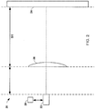
- FIG. 3 illustrates yet another example system 30 for evaluating the modulation transfer function of a camera 32.
- a mirror 35 is used in the optical pathway 37 to further reduce the size and the space between the relay lens 36 and the monitor 34.
- the system 30 includes an image source 34 configured to provide light in a pattern representing a desired image.
- the image source 34 includes a dynamic display such as an LCD monitor.
- a lens 36 is configured to direct the provided light from the image source 34 toward the camera 32 such that the desired image appears as a virtual image 34'.
- the lens 36 is a plano-convex lens. Images captured by the camera can be provided to an image analysis component 38 for calculation of the MTF.
- a mirror 35 is tilted at approximately 34°, and the image source 34 is tilted at approximately 22° as shown in FIG 3 .
- the footprint of the testing assembly is significantly decreased.
- a test of substantially identical quality can be performed in a footprint of only 85 mm x 65 mm x 60 mm. It will be appreciated that this reduced footprint can provide significant savings in cost and increase the ease of use of the system.
- the system of FIGS. 2 and 3 has been found to provide a mean MTF value for the device under test within five percent of that of approved method data at a ninety-five percent confidence level.
- a set of targets is located at a hyper-focal distance of the camera.
- the device under test and the targets are separated by a hyper-focal distance of the camera, and the targets are provided at an illuminated target, such as on an LCD monitor.
- Light from the targets is captured by the DUT, and metrics are measured and utilized to provide MTF scores of the available slant edges measured by the module.
- FIG. 4 illustrates another example of a system 50 for evaluating the modulation transfer function of a camera 52.
- the system 50 includes an image projector 54 configured to provide light in a pattern representing a desired image.
- the image projector 54 includes a light source that is passed through a patterned plate to project the desired pattern.
- the light source can include a laser at a desired wavelength to provide a narrow band but already collimated source of light, or a non-coherent source, such as a light emitting diode (LED), a fluorescent bulb, or an incandescent bulb, to provide a wider spectrum.
- a lens 56 is configured to direct the provided light from the image source toward the camera 52 as a collimated beam. In the illustrated implementation, the lens 56 is a doublet objective lens. Images captured by the camera can be provided to an image analysis component 58 for calculation of the MTF.
- FIG. 5 illustrates one example of a collimated target source 100, representing the image source 54 and lens 56 of FIG. 2 , that can be used in a system for evaluating the modulation transfer function of a camera.
- the collimated target source 100 comprises a plurality of optical components 102, 104, 106, 108, and 110 placed within a housing (not shown).
- the optical components include a light source 102, which can provide coherent or non-coherent light.
- the light source 102 is a white LED light emitting diode with a spectrum from 440 to 660 nm. The diode was encapsulated in a round clear epoxy casing with a five (5) mm diameter.
- An aspheric condenser lens 104 is used to make the output of the light source less divergent.
- the focal length of the lens is 8 mm with a 12.7 mm diameter.
- the light source 102 is placed at the focal point of the lens 104.
- a fine grit diffuser 106 is located forward of the condenser lens 104 to homogenize the illumination source.
- a patterned reticle 108 is used to apply a desired pattern to the light source.
- the reticle 108 is made from patterned metal, such as chrome, on glass to produce a desired target. It will be appreciated, however, that the reticle 108 can include patterning with a material that is transparent to a specific band of wavelengths, as well as fully or partially opaque materials, to project a desired color or grayscale image.
- the reticle 108 can have a total diameter of 12.7 mm, with the patterned target having a width of about 2.4 mm.
- Transmitted light through the reticle is collimated by an objective lens 110, with the reticle 108 placed at the back focal length of the objective lens.
- a thirty (30) mm focal length achromatic doublet lens is used to collimate the transmitted light from the reticle 108.
- the objective lens 110 can have an antireflective coating effective across the visible range (e.g., for wavelengths from 400 nm to 700 nm). It will be appreciated that the doublet design significantly reduces the chromatic aberration. This is of particular importance, as minimizing the distortion introduced by the lens reduces the complexity of accounting for the lens in the MTF evaluation of the device under test.
- the target source 100 has a total length of approximately one hundred sixty (160) mm, and a diameter of approximately thirteen (13) mm.
- the light source 102 is separated from the condenser lens 104 by approximately eight (8) mm.
- the condenser lens 104 is separated from the diffuser 106 by approximately thirty (30) mm.
- the diffuser 106 is separated from the reticle 108 by approximately seventy (70) mm, and the objective lens 110 is separated from the reticle 108 by about twenty seven and a half (27.5) mm.
- FIG. 6 illustrates a schematic diagram of a testing system 150 in accordance with an aspect of the present invention.
- FIG. 7 depicts the testing system 150 of FIG. 6 along a cross-section passing through a center point of an aperture of the device under test.
- the system 150 utilizes eleven collimated target sources 152-162 arranged within a field of view of a device under test 164, such that each target source projects a collimated beam into an aperture of the device under test.
- a first target source 152 referred to as an "on-axis" source is positioned and oriented as to provide light to a center of an aperture of the device under test, while a plural set of "off-axis" target sources 153-162, are positioned and oriented to provide light to positions with the aperture that are spatially separated from the center of the aperture.
- targets of substantially equal size are desired, and thus the plurality of target sources are positioned such that each of the target sources 152-162 is equidistant from the device under test.
- this distance is fifty (50) mm, and the device under test 164 has a hyper-focal distance of approximately five (5) m. Accordingly, the distance between the target sources 152-162 and the device under test 164 can be reduced less than two percent.
- the plurality of target sources can project a same pattern or different patterns, according to the desired application.
- the desired targets are identical, but some targets are at different orientations than others.
- each of the target sources can be identical, but a first target source can be rotated, relative to a second target source, along an axis coinciding with a direction of its projected collimated beam, such that a first image received at the device under test from the first target source is rotated relative to a second image received at the device under test from the second target source.
- This illustrated compact MTF testing assembly 150 allows for a significant decrease in the necessary footprint for MTF testing providing a virtual image to the device under test.
- light reaching a device under test from a wall target at hyper-focal distance represents nearly parallel beams.
- each target source 152-162 produces a collimated beam, eliminating the requirement of placing the device under test 164 at the hyper-focal distance.
- the footprint of the testing assembly is significantly decreased.
- a test of substantially identical quality can be performed in a footprint of only 85 mm x 65 mm x 60 mm. It will be appreciated that this reduced footprint can provide significant savings in cost and increase the ease of use of the system.
- the system of FIGS. 6 and 7 has been found to provide a mean MTF value for the device under test within five percent of that of approved method data at a ninety-five percent confidence level.
- FIGS. 8 and 9 example methodologies will be better appreciated with reference to FIGS. 8 and 9 . While, for purposes of simplicity of explanation, the methodologies of FIGS. 8 and 9 are shown and described as executing serially, it is to be understood and appreciated that the present invention is not limited by the illustrated order, as some actions could in other examples occur in different orders and/or concurrently from that shown and described herein.
- FIG. 8 illustrates a method 800 for evaluating the modulation transfer function (MTF) of a device under test.
- a camera, a lens and a display are arranged along a common optical axis to provide a magnified virtual image that replicates a real image at a hyper-focal distance.
- a target pattern is generated on the display directly to an aperture of the camera through the lens. It will be appreciated that, in accordance with an aspect of the present invention, the display can be separated from the camera by less than two percent of a hyper-focal distance of the device under test.
- At least one image of the target pattern is captured at 806.
- the MTF for the camera under test is calculated from the at least one image taken at the camera and the known characteristics of the lens.
- a test can be employed on the system.
- an optical check can determine if the relay lens aperture is sufficient to cover the field of view (FOV) of the S-cam system, and the mirror size is sufficient to cover the FOV of S-cam and lens.
- a ray-tracing diagram with the detailed S-cam optical specifications can be employed to verify the entrance pupils of the S-cam camera to ensure that both are greater than the FOV.
- FIG. 9 illustrates a method 900 for evaluating the modulation transfer function (MTF) of a device under test.
- a collimated beam of patterned light is projected directly to an aperture of the device under test through an objective lens.
- the source of the collimated beam of light can be separated from the device under test by less than two percent of a hyper-focal distance of the device under test.
- a plurality of collimated beams of patterned light can be provided directly to the aperture of the device under test from a plurality of target sources, with each target source including a light source, a patterned reticle, and an objective lens. At least one image of the patterned light is captured at 904.
- each of the captured at least one image represents the plurality of collimated beams of patterned light.
- the MTF for the device under test is calculated from the at least one image taken at the device under test and the known characteristics of the objective lens.
Landscapes
- Physics & Mathematics (AREA)
- General Physics & Mathematics (AREA)
- Engineering & Computer Science (AREA)
- Optics & Photonics (AREA)
- Chemical & Material Sciences (AREA)
- Analytical Chemistry (AREA)
- Health & Medical Sciences (AREA)
- Biomedical Technology (AREA)
- General Health & Medical Sciences (AREA)
- Multimedia (AREA)
- Signal Processing (AREA)
- Testing Of Optical Devices Or Fibers (AREA)
Description
- This invention relates to optics, and more particularly, to a compact modulation transfer function evaluation system for a camera.
- The modulation transfer function ("MTF") of a camera is a measurement of the camera's ability to transfer contrast at a particular resolution from an imaged object to a camera image. The MTF is a way to incorporate resolution and contrast into a single specification. MTF is the key to measure the sharpness of image, and to quantify the overall imaging performance of a camera system in terms of resolution and contrast. As a result, knowing the MTF of each imaging lens and camera sensor within a system allows a designer to make the appropriate selection when optimizing the camera system for a particular resolution.
-
US 5 748 230 A relates to a system for automatically performing the Minimum Resolvable Contrast (MRC) test on an image sensor using a digital signal processor for controlling the testing, wherein an edge response from a square aperture target edge is used to generate a Modulation Transfer Function which, in combination with signal and noise data obtained using the square aperture target, provides an input to automated MRC (AMRC) processing equations. Furthermore,US 4 241 996 A relates to an apparatus for determining the quality of optical equipment through measurement of the modulation transfer function of the same. - In accordance with the present invention, systems and methods are provided for evaluating the modulation transfer function (MTF) of a device under test, as set forth in
claims 1 to 8. -
-
FIG. 1 illustrates an example of a system for evaluating the modulation transfer function of a camera; -
FIG. 2 illustrates another example of a system for evaluating the modulation transfer function of a camera; -
FIG. 3 illustrates yet another example of a system for evaluating the modulation transfer function of a camera; -
FIG. 4 illustrates still another example of a system for evaluating the modulation transfer function of a camera; -
FIG. 5 illustrates one example of a collimated target source that can be used in system for evaluating the modulation transfer function of a camera; -
FIG. 6 illustrates a schematic diagram of a testing system in accordance with the present invention; -
FIG. 7 depicts the testing system ofFIG. 6 along a cross-section passing through a center point of an aperture of the device under test in accordance with the present invention; -
FIG. 8 illustrates amethod 800 for evaluating the modulation transfer function (MTF) of a device under test; and -
FIG. 9 illustrates anothermethod 900 for evaluating the modulation transfer function (MTF) of a device under test. - One method of determining the modulation transfer function ("MTF") of a camera has been to place a set of targets at a hyper-focal distance of the camera. In one implementation of this method, printed targets are mounted to a wall. There are total of eleven targets, with one for on-axis measurements and the other ten used for off-axis measurements. The device under test ("DUT") and the targets are separated by a hyper-focal distance of the camera, and the wall targets are illuminated by an LED light panel. Reflected light from the targets is captured by the DUT, and metrics are measured and utilized to provide MTF scores of the available slant edges measured by the module. While this is an effective method for camera testing, the hyper-focal distance of many cameras is significant, and the method can require a very large testing footprint. In one camera used in intelligent vehicle safety systems, the hyper-focal distance is five (5) m, and the method requires a working space having a volume of 3.44 m x 2.74 m x 5 m. Further, the targets are not always illuminated by an equal amount of light.
- In particular, cameras are often incorporated in a vehicle platform to provide additional information to intelligent vehicle safety systems to aid the driver. One or more cameras may be mounted in various locations around the vehicle, placed to provide additional awareness of environmental conditions to the driver and to intelligent vehicle safety systems. For example, a driver assist camera can be placed near or on the vehicle windshield to ensure a maximum field of view of the environment in front of the car. Additionally or alternatively, cameras can be placed so as to view the rear of the vehicle, for assisting when the vehicle is moving in reverse, or top or side views to aid in greater situational awareness. To ensure proper operation of the cameras and therefore ensure useful data is provided to the vehicle's intelligent safety systems, tests can be performed to ensure that the installed cameras are suitable for a vehicle platform. Thus, as noted, a vehicle may employ a camera with a five (5) m hyper-focal distance or an alternative hyper-focal distance, and perform a method for determining the MTF of the camera, in accordance with the principles and examples provided herein.
-
FIG. 1 illustrates an example of asystem 10 for evaluating the modulation transfer function of a device undertest 12 in accordance with the present invention. Thesystem 10 includes anobject 14 configured to provide a pattern representing a desired image. In one implementation, theobject 14 includes an appropriate coherent or non-coherent light source passed through a transparent plate having a pattern of opaque or translucent material thereon to provide the desired pattern. For example, the light source can include a laser at a desired wavelength to provide a narrow band but already collimated source of light, or a non-coherent source having a wider spectrum. Alternatively, theobject 14 can represent a display, such as a LCD display, provided with appropriate input to display one or more targets. - A
lens 16 is configured to direct light representing the provided pattern from the image source toward the device undertest 12. In accordance with one example embodiment of the present invention, thelens 16 is a doublet objective lens. It will be appreciated that thesystem 10 could include multiple images sources and lens (not shown) to provide a plurality of targets to the device undertest 12. At least one image from the device undertest 12 is provided to animage analysis component 18. Theimage analysis component 18 is configured to calculate a MTF for the device undertest 12 from the at least one image taken at the device undertest 12 and the known characteristics of theobject 14 and thelens 16. -
FIG. 2 illustrates another example of asystem 30 for evaluating the modulation transfer function of a device undertest 32 in accordance with the present invention. Thesystem 30 includes animage source 34 configured to provide a pattern representing a desired image. In one implementation, theimage source 34 includes an appropriate coherent or non-coherent light source passed through a transparent plate having a pattern of opaque or translucent material thereon to provide the desired pattern. Alternatively, theimage source 34 can represent a display, such as a LCD display, provided with appropriate input to display one or more targets, such as theexample target arrangement 166 illustrated inFIG. 7 . Additionally or alternatively, theimage source 34 can be a dynamic display, such that the target arrangement can modified in real time as the desired image and or testing conditions require. In the illustrated example, the distance between therelay lens 36 andimage source 34 is reduced to approximately 370 mm, such that theoptical test system 30 provides functionality similar to a larger, full size and full distance 5 m test system. - A
lens 36 is configured to direct light representing the provided pattern from the image source toward the device undertest 32. Further, a virtual image is created at theimage source 34 simulating the effect of placing a target object in a test environment at 5 m. Note that thelens 36 could be multiple lenses with different optical properties employed to improve the image of the object, modify the virtual distance of the object, or other considerations for image capture and processing. In the example ofFIG. 2 , therelay lens 36 can be, for example, a plano-convex lens. Further, the location and arrangement of elements can be calculated by employing the Gaussian thin lens formula as shown in Equation 1:
- In
Equation 1, f is the focus length of a thin lens, such aslens 36, S2 is the distance of the virtual image from the center oflens 36, and S1 is the object distance to the center of the lens. S1 is positive if the object is on the left side of the lens. S1 is negative if the object is on the right side oflens 36. S2 is positive if the object is on the right side oflens 36, S2 is negative if the object is on the left side oflens 36. If f is substituted with f = 400 mm = 0.4 m, and S2 = -5 m are put intoEquation 1, then S1=370.4 mm. Accordingly, theimage source 34 can be positioned at a distance of S1=370.4 mm from the relay lens. In order to ensure an enlarged vertical image, the object, here a virtual image on theimage source 34, should be placed before the calculated focus point, such as 370.4 mm < 400 mm. - In the
example system 30, the virtual image should have a transverse magnification determined as the ratio of the hyper-focal distance and the distance between the lens and theimage source 34. Thus, the transverse magnification can be calculated as MT= 5/0.3704=13.5 in order to replicate a target image at a distance of 5 m. Therefore, in order to replicate an object with dimensions of 164"x112" at 5 m, the virtual image on the image source 64 should be approximately 12.15"X 8.3". In one example, theimage source 34 is a monitor dimensioned at 24" which is sufficient to display the target image with the appropriate dimensions. - In accordance with one example embodiment of the present invention, the
lens 36 is a doublet objective lens. It will be appreciated that thesystem 30 could include multiple images sources and lens (not shown) to provide a plurality of targets to the device undertest 32. At least one image from the device undertest 32 is provided to animage analysis component 38. Theimage analysis component 38 is configured to calculate a MTF for the device undertest 32 from the at least one image taken at the device undertest 32 and the known characteristics of theimage source 34 and thelens 36. Moreover, in a test comparison of the MTFoptical test system 30 and a full size and full distance 5 m test system, image quality sharpness comparison between systems suggest that theoptical test system 30 provides a strong correlation of image quality in comparison to the full size and full distance 5 m test system. -
FIG. 3 illustrates yet anotherexample system 30 for evaluating the modulation transfer function of acamera 32. In the example ofFIG. 3 , amirror 35 is used in theoptical pathway 37 to further reduce the size and the space between therelay lens 36 and themonitor 34. Thesystem 30 includes animage source 34 configured to provide light in a pattern representing a desired image. In the illustrated implementation, theimage source 34 includes a dynamic display such as an LCD monitor. Alens 36 is configured to direct the provided light from theimage source 34 toward thecamera 32 such that the desired image appears as avirtual image 34'. In the illustrated implementation, thelens 36 is a plano-convex lens. Images captured by the camera can be provided to animage analysis component 38 for calculation of the MTF. In the illustrated implementation, amirror 35 is tilted at approximately 34°, and theimage source 34 is tilted at approximately 22° as shown inFIG 3 . To ensure the center beam of the optical signal from theimage source 34 is measured from the center of the monitor to the center axis of thelens 36, the tilt angles ofimage source 34 andmirror 35 should be designed as the total angle: 34° + 34° + 22° = 90°. Therefore, the tilt angles comply with established optical principles. - As a result, the footprint of the testing assembly is significantly decreased. In the example of
FIGS. 2 and3 , a test of substantially identical quality can be performed in a footprint of only 85 mm x 65 mm x 60 mm. It will be appreciated that this reduced footprint can provide significant savings in cost and increase the ease of use of the system. In comparisons with the standard arrangement, the system ofFIGS. 2 and3 has been found to provide a mean MTF value for the device under test within five percent of that of approved method data at a ninety-five percent confidence level. - In yet another method of determining the MTF of a camera, a set of targets is located at a hyper-focal distance of the camera. The device under test and the targets are separated by a hyper-focal distance of the camera, and the targets are provided at an illuminated target, such as on an LCD monitor. Light from the targets is captured by the DUT, and metrics are measured and utilized to provide MTF scores of the available slant edges measured by the module.
-
FIG. 4 illustrates another example of asystem 50 for evaluating the modulation transfer function of acamera 52. Thesystem 50 includes animage projector 54 configured to provide light in a pattern representing a desired image. In the illustrated implementation, theimage projector 54 includes a light source that is passed through a patterned plate to project the desired pattern. For example, the light source can include a laser at a desired wavelength to provide a narrow band but already collimated source of light, or a non-coherent source, such as a light emitting diode (LED), a fluorescent bulb, or an incandescent bulb, to provide a wider spectrum. Alens 56 is configured to direct the provided light from the image source toward thecamera 52 as a collimated beam. In the illustrated implementation, thelens 56 is a doublet objective lens. Images captured by the camera can be provided to animage analysis component 58 for calculation of the MTF. -
FIG. 5 illustrates one example of a collimatedtarget source 100, representing theimage source 54 andlens 56 ofFIG. 2 , that can be used in a system for evaluating the modulation transfer function of a camera. In the illustrated example embodiment, the collimatedtarget source 100 comprises a plurality ofoptical components light source 102, which can provide coherent or non-coherent light. In accordance with one example embodiment, thelight source 102 is a white LED light emitting diode with a spectrum from 440 to 660 nm. The diode was encapsulated in a round clear epoxy casing with a five (5) mm diameter. Anaspheric condenser lens 104 is used to make the output of the light source less divergent. In the example embodiment, the focal length of the lens is 8 mm with a 12.7 mm diameter. Thelight source 102 is placed at the focal point of thelens 104. - A
fine grit diffuser 106 is located forward of thecondenser lens 104 to homogenize the illumination source. A patternedreticle 108 is used to apply a desired pattern to the light source. In the example embodiment, thereticle 108 is made from patterned metal, such as chrome, on glass to produce a desired target. It will be appreciated, however, that thereticle 108 can include patterning with a material that is transparent to a specific band of wavelengths, as well as fully or partially opaque materials, to project a desired color or grayscale image. In the illustrated implementation, thereticle 108 can have a total diameter of 12.7 mm, with the patterned target having a width of about 2.4 mm. - Transmitted light through the reticle is collimated by an
objective lens 110, with thereticle 108 placed at the back focal length of the objective lens. In accordance with the example embodiment, a thirty (30) mm focal length achromatic doublet lens is used to collimate the transmitted light from thereticle 108. Theobjective lens 110 can have an antireflective coating effective across the visible range (e.g., for wavelengths from 400 nm to 700 nm). It will be appreciated that the doublet design significantly reduces the chromatic aberration. This is of particular importance, as minimizing the distortion introduced by the lens reduces the complexity of accounting for the lens in the MTF evaluation of the device under test. - In the illustrated examples, the
target source 100 has a total length of approximately one hundred sixty (160) mm, and a diameter of approximately thirteen (13) mm. Thelight source 102 is separated from thecondenser lens 104 by approximately eight (8) mm. Thecondenser lens 104 is separated from thediffuser 106 by approximately thirty (30) mm. Thediffuser 106 is separated from thereticle 108 by approximately seventy (70) mm, and theobjective lens 110 is separated from thereticle 108 by about twenty seven and a half (27.5) mm. - It will be appreciated that a test system could include multiple targets sources, such as those described in
FIG. 5 , to provide a plurality of targets to a device under test for analysis.FIG. 6 illustrates a schematic diagram of atesting system 150 in accordance with an aspect of the present invention.FIG. 7 depicts thetesting system 150 ofFIG. 6 along a cross-section passing through a center point of an aperture of the device under test. - In the illustrated example, the
system 150 utilizes eleven collimated target sources 152-162 arranged within a field of view of a device undertest 164, such that each target source projects a collimated beam into an aperture of the device under test. Afirst target source 152, referred to as an "on-axis" source is positioned and oriented as to provide light to a center of an aperture of the device under test, while a plural set of "off-axis" target sources 153-162, are positioned and oriented to provide light to positions with the aperture that are spatially separated from the center of the aperture. In the illustrated implementation, targets of substantially equal size are desired, and thus the plurality of target sources are positioned such that each of the target sources 152-162 is equidistant from the device under test. In the illustrated implementation, this distance is fifty (50) mm, and the device undertest 164 has a hyper-focal distance of approximately five (5) m. Accordingly, the distance between the target sources 152-162 and the device undertest 164 can be reduced less than two percent. - It will be appreciated that the plurality of target sources can project a same pattern or different patterns, according to the desired application. In one analysis of the MTF for a device under test compatible with the illustrated
system 150, the desired targets are identical, but some targets are at different orientations than others. To simply manufacture of the plurality of target sources 152-162, each of the target sources can be identical, but a first target source can be rotated, relative to a second target source, along an axis coinciding with a direction of its projected collimated beam, such that a first image received at the device under test from the first target source is rotated relative to a second image received at the device under test from the second target source. - This illustrated compact
MTF testing assembly 150 allows for a significant decrease in the necessary footprint for MTF testing providing a virtual image to the device under test. In the standard system, light reaching a device under test from a wall target at hyper-focal distance represents nearly parallel beams. In the proposed method, each target source 152-162 produces a collimated beam, eliminating the requirement of placing the device undertest 164 at the hyper-focal distance. As a result, the footprint of the testing assembly is significantly decreased. In the example OFFIGS. 6 and 7 , a test of substantially identical quality can be performed in a footprint of only 85 mm x 65 mm x 60 mm. It will be appreciated that this reduced footprint can provide significant savings in cost and increase the ease of use of the system. In comparisons with the standard arrangement, the system ofFIGS. 6 and 7 has been found to provide a mean MTF value for the device under test within five percent of that of approved method data at a ninety-five percent confidence level. - In view of the foregoing structural and functional features described above in
FIGS. 1-7 , example methodologies will be better appreciated with reference toFIGS. 8 and 9 . While, for purposes of simplicity of explanation, the methodologies ofFIGS. 8 and 9 are shown and described as executing serially, it is to be understood and appreciated that the present invention is not limited by the illustrated order, as some actions could in other examples occur in different orders and/or concurrently from that shown and described herein. -
FIG. 8 illustrates amethod 800 for evaluating the modulation transfer function (MTF) of a device under test. At 802, a camera, a lens and a display are arranged along a common optical axis to provide a magnified virtual image that replicates a real image at a hyper-focal distance. At 804, a target pattern is generated on the display directly to an aperture of the camera through the lens. It will be appreciated that, in accordance with an aspect of the present invention, the display can be separated from the camera by less than two percent of a hyper-focal distance of the device under test. At least one image of the target pattern is captured at 806. At 808, the MTF for the camera under test is calculated from the at least one image taken at the camera and the known characteristics of the lens. Moreover, a test can be employed on the system. At 810, an optical check can determine if the relay lens aperture is sufficient to cover the field of view (FOV) of the S-cam system, and the mirror size is sufficient to cover the FOV of S-cam and lens. Additionally, at 812 a ray-tracing diagram with the detailed S-cam optical specifications can be employed to verify the entrance pupils of the S-cam camera to ensure that both are greater than the FOV. -
FIG. 9 illustrates amethod 900 for evaluating the modulation transfer function (MTF) of a device under test. At 902, a collimated beam of patterned light is projected directly to an aperture of the device under test through an objective lens. It will be appreciated that, in accordance with an aspect of the present invention, the source of the collimated beam of light can be separated from the device under test by less than two percent of a hyper-focal distance of the device under test. In one example, a plurality of collimated beams of patterned light can be provided directly to the aperture of the device under test from a plurality of target sources, with each target source including a light source, a patterned reticle, and an objective lens. At least one image of the patterned light is captured at 904. In the implementation using plural target sources, each of the captured at least one image represents the plurality of collimated beams of patterned light. At 906, the MTF for the device under test is calculated from the at least one image taken at the device under test and the known characteristics of the objective lens.
Claims (8)
- A system for evaluating the modulation transfer function, in short MTF of a device under test (164), comprising:an image projector (54) configured to provide light in a pattern representing a desired image;a lens (56) configured to direct the provided light toward the device under test (164) as a collimated beam, wherein the lens (56) is selected to provide a magnified virtual image to replicate an image at a hyper-focal distance for the device under test (164); andan image analysis component (58) configured to calculate the MTF for the device under test (164) from at least one image of the desired image taken by the device under test (164) and the known characteristics of the image projector (54) and the lens (56),each of the image projector (54) and the lens (56) are positioned within a housing to form a target source (152-162) configured to project the desired image to an aperture of the device under test (164), andthat the system comprises a plurality of target sources (152-162), each comprising an image projector (54) and a lens (56).
- The system of claim 1, wherein the lens (56) is an achromatic doublet lens.
- The system of claim 1, wherein the image projector (54) comprises a light source (102) and a patterned reticle (108), positioned such that a pattern on the patterned reticle (108) is projected toward the device under test (164), wherein optionally, the lens (56) is a first lens, and the image projector (54) further comprises a second lens (104) positioned between the light source (102) and the patterned reticle (108), the patterned reticle (108) being positioned between the first lens (56) and the second lens (104), and wherein the first lens (56) is preferably an achromatic doublet lens and the second lens (104) is preferably an aspherical condenser lens.
- The system of claim 3, the image projector (54) further comprising a diffuser (106), configured to homogenize light from the light source (102), the diffuser (106) being positioned between the light source (102) and the patterned reticle (108).
- The system of claim 1, wherein the plurality of target sources (152-162) is positioned such that each of the target sources (152-162) is substantially equidistant from the device under test (164) and wherein the distance from each target source (152-162) to the device under test (164) is preferably less than two percent of a hyper-focal distance of the device under test (164).
- The system of claim 5, wherein the plurality of target sources (152-162) comprise a first target source, positioned and oriented as to provide light to a center of an aperture of the device under test (164), and at least two other target sources, positioned and oriented to provide light to positions with the aperture that are spatially separated from the center of the aperture, and/or wherein each of the plurality of target sources (152-162) is configured to provide a collimated beam of light in a given direction, the plurality of target sources (.152-162) comprising a first target source that is rotated, relative to a second target source, along an axis coinciding with given direction, such that a first image received at the device under test (164) from the first target source is rotated relative to a second image received at the device under test (164) from the second target source.
- A method for evaluating the modulation transfer function, in short MTF, of a device under test (164), comprising:projecting a collimated beam of patterned light directly to an aperture of the device under test through an objective lens (58), wherein the objective lens (58) is selected to provide a magnified virtual image of the patterned light to replicate an image at a hyper-focal distance for the device under test (164);capturing at least one image of the patterned light at the device under test (164); andcalculate the MTF for the device under test (164) from the at least one image of patterned light captured by the device under test (164) and the known characteristics of the objective lens (58),projecting the collimated beam of patterned light directly to the aperture of the device under test (164) through the objective lens (56) comprises projecting a plurality of collimated beams of patterned light directly to the aperture of the device under test (164) from a plurality of target sources (152-162), each including a light source (102), a reticle (108), and an objective lens (56), such that each of the captured at least one image represents the plurality of collimated beams of patterned light.
- The method of claim 7, wherein projecting the collimated beam of patterned light directly to the aperture of the device under test (164) through the objective lens (56) comprises projecting the collimated beam of patterned light from a distance less than two percent of a hyper-focal distance of the device under test (164).
Applications Claiming Priority (3)
| Application Number | Priority Date | Filing Date | Title |
|---|---|---|---|
| US201462088878P | 2014-12-08 | 2014-12-08 | |
| US201562109098P | 2015-01-29 | 2015-01-29 | |
| PCT/US2015/064456 WO2016094383A1 (en) | 2014-12-08 | 2015-12-08 | Compact modular transfer function evaluation system |
Publications (3)
| Publication Number | Publication Date |
|---|---|
| EP3230776A1 EP3230776A1 (en) | 2017-10-18 |
| EP3230776A4 EP3230776A4 (en) | 2018-08-08 |
| EP3230776B1 true EP3230776B1 (en) | 2021-05-26 |
Family
ID=56108048
Family Applications (1)
| Application Number | Title | Priority Date | Filing Date |
|---|---|---|---|
| EP15867096.8A Active EP3230776B1 (en) | 2014-12-08 | 2015-12-08 | Compact modular transfer function evaluation system |
Country Status (4)
| Country | Link |
|---|---|
| US (1) | US10704984B2 (en) |
| EP (1) | EP3230776B1 (en) |
| CN (1) | CN107111013B (en) |
| WO (1) | WO2016094383A1 (en) |
Families Citing this family (10)
| Publication number | Priority date | Publication date | Assignee | Title |
|---|---|---|---|---|
| US10521977B2 (en) * | 2017-03-27 | 2019-12-31 | GM Global Technology Operations LLC | Methods and systems for integrated vehicle sensor calibration and maintenance |
| CN110662020B (en) * | 2019-09-05 | 2021-06-11 | 北京空间机电研究所 | Transfer function testing system and method based on auto-collimation principle |
| US11394955B2 (en) * | 2020-01-17 | 2022-07-19 | Aptiv Technologies Limited | Optics device for testing cameras useful on vehicles |
| US20210233500A1 (en) * | 2020-01-29 | 2021-07-29 | Dell Products L.P. | System and Method for Dynamically Focusing an Information Handling System Display Screen Based on User Vision Requirements |
| CN113848041B (en) * | 2021-09-27 | 2024-04-30 | 歌尔光学科技有限公司 | Optical performance testing system and testing method |
| US12429400B1 (en) | 2021-12-22 | 2025-09-30 | Meta Platforms Technologies, Llc | Optical transmission tester |
| US12108025B2 (en) | 2021-12-22 | 2024-10-01 | Meta Platforms Technologies, Llc | Eye-tracking optical verification tester |
| CN114754982B (en) * | 2022-04-15 | 2023-03-24 | 电子科技大学 | An automatic test device and method for eye point distance of an intelligent optical sight |
| FR3143118B1 (en) * | 2022-12-08 | 2024-12-06 | Safran Electronics & Defense | Optical quality measurement method |
| US12028509B1 (en) * | 2023-12-04 | 2024-07-02 | Mloptic Corp. | Diffraction-limited optical target system with continuously-variable virtual distance |
Family Cites Families (13)
| Publication number | Priority date | Publication date | Assignee | Title |
|---|---|---|---|---|
| US4241996A (en) * | 1976-12-06 | 1980-12-30 | Exotech, Incorporated | Apparatus for measuring the quality of optical equipment |
| US5748230A (en) * | 1995-10-27 | 1998-05-05 | Northrop Grumman Corporation | Automated minimum resolvable contrast (AMRC) test |
| US6333826B1 (en) | 1997-04-16 | 2001-12-25 | Jeffrey R. Charles | Omniramic optical system having central coverage means which is associated with a camera, projector, or similar article |
| US6813008B2 (en) * | 2002-06-10 | 2004-11-02 | Palantyr Research, Llc | Microdissection optical system |
| US6977717B1 (en) * | 2003-12-04 | 2005-12-20 | Advanced Micro Devices, Inc. | Method and device for determining projection lens pupil transmission distribution and illumination intensity distribution in photolithographic imaging system |
| JP2009264894A (en) * | 2008-04-24 | 2009-11-12 | Nikon Corp | Inspection device |
| CA2809581C (en) * | 2010-08-27 | 2016-11-15 | The Board Of Trustees Of The Leland Stanford Junior University | Microscopy imaging device with advanced imaging properties |
| KR101233978B1 (en) * | 2010-09-29 | 2013-02-18 | 이동희 | Optical scope |
| US9217687B2 (en) * | 2012-03-31 | 2015-12-22 | Optikos Corporation | Image analysis system and methods for IR optics |
| US8866912B2 (en) * | 2013-03-10 | 2014-10-21 | Pelican Imaging Corporation | System and methods for calibration of an array camera using a single captured image |
| US10190960B2 (en) | 2013-03-14 | 2019-01-29 | Cytonome/St, Llc | Micro-lens systems for particle processing systems |
| US20140320672A1 (en) * | 2013-04-29 | 2014-10-30 | Cooke Optics Limited | Method and Apparatus for Measuring Flange Back Focus and Calibrating Track Length Scales of Photographic Objective Lenses |
| CN103913293B (en) * | 2014-03-12 | 2016-04-06 | 华北水利水电大学 | Coded structured light system optics TRANSFER MODEL measuring system |
-
2015
- 2015-12-08 EP EP15867096.8A patent/EP3230776B1/en active Active
- 2015-12-08 US US15/531,625 patent/US10704984B2/en active Active
- 2015-12-08 CN CN201580072556.4A patent/CN107111013B/en active Active
- 2015-12-08 WO PCT/US2015/064456 patent/WO2016094383A1/en not_active Ceased
Non-Patent Citations (1)
| Title |
|---|
| None * |
Also Published As
| Publication number | Publication date |
|---|---|
| WO2016094383A1 (en) | 2016-06-16 |
| CN107111013B (en) | 2020-11-06 |
| CN107111013A (en) | 2017-08-29 |
| EP3230776A1 (en) | 2017-10-18 |
| US10704984B2 (en) | 2020-07-07 |
| US20170307469A1 (en) | 2017-10-26 |
| EP3230776A4 (en) | 2018-08-08 |
Similar Documents
| Publication | Publication Date | Title |
|---|---|---|
| US10704984B2 (en) | Compact modular transfer function evaluation system | |
| US20140152845A1 (en) | camera testing device and method for testing a camera | |
| US10750165B2 (en) | Object simulation unit for testing a camera objective and diagnostic system | |
| JP2025540779A (en) | DEVICE AND METHOD FOR DETERMINING IMAGING QUALITY OF AT LEAST ONE IMAGE OF AN INSPECTED ARTICLE - Patent application | |
| CN101644603B (en) | Large-visual-field wide-wave-band optical analog system based on digital micromirror array view | |
| CN109799672B (en) | Detection device and method for imperfect imaging lens | |
| CN109632269A (en) | Method based on image grayscale infomation detection diffractive-optical element performance | |
| CN110174816A (en) | It determines the method for mask focal position and executes the gauging system of this method | |
| CN108168469A (en) | A kind of plain shaft parallelism detecting system and method | |
| JP5450975B2 (en) | Measuring apparatus and measuring method | |
| KR101447857B1 (en) | Particle inspectiing apparatus for lens module | |
| CN118980497B (en) | NED lens-based imaging spectrometer point spread function measurement method and device | |
| CN112525343A (en) | Detection method and device for dispersive imaging spectrometer | |
| KR102010136B1 (en) | Imaging system for Obtaining multi-mode images | |
| CN106643798B (en) | A Visible Light Target Simulation System | |
| CN111419172B (en) | Image quality detection method and detection device for vision detection system | |
| US10627309B1 (en) | Micro-distance lens detection device | |
| EP4624890A1 (en) | Optical testing device and method of operating an optical testing device | |
| KR20180051148A (en) | Method for analyzing stray light and apparatus performing the same | |
| CN113295187B (en) | Infinity position calibration method and system for optical target simulation system | |
| CN119788838B (en) | Halation testing device and method for low-light night vision camera | |
| CN111586402A (en) | A kind of visible light space camera static transfer test system and test method | |
| US20250324153A1 (en) | Wavefront detection system and building method of optical path | |
| RU2325679C2 (en) | Indicator on windscreen | |
| JP2010014463A (en) | Method of measuring optical element and method of manufacturing optical element |
Legal Events
| Date | Code | Title | Description |
|---|---|---|---|
| STAA | Information on the status of an ep patent application or granted ep patent |
Free format text: STATUS: THE INTERNATIONAL PUBLICATION HAS BEEN MADE |
|
| PUAI | Public reference made under article 153(3) epc to a published international application that has entered the european phase |
Free format text: ORIGINAL CODE: 0009012 |
|
| STAA | Information on the status of an ep patent application or granted ep patent |
Free format text: STATUS: REQUEST FOR EXAMINATION WAS MADE |
|
| 17P | Request for examination filed |
Effective date: 20170606 |
|
| AK | Designated contracting states |
Kind code of ref document: A1 Designated state(s): AL AT BE BG CH CY CZ DE DK EE ES FI FR GB GR HR HU IE IS IT LI LT LU LV MC MK MT NL NO PL PT RO RS SE SI SK SM TR |
|
| AX | Request for extension of the european patent |
Extension state: BA ME |
|
| DAV | Request for validation of the european patent (deleted) | ||
| DAX | Request for extension of the european patent (deleted) | ||
| A4 | Supplementary search report drawn up and despatched |
Effective date: 20180705 |
|
| RIC1 | Information provided on ipc code assigned before grant |
Ipc: G05B 23/02 20060101ALI20180629BHEP Ipc: H04N 17/00 20060101ALI20180629BHEP Ipc: G02B 5/02 20060101AFI20180629BHEP Ipc: G01M 11/02 20060101ALI20180629BHEP Ipc: G02B 25/02 20060101ALI20180629BHEP Ipc: G02B 27/00 20060101ALI20180629BHEP |
|
| STAA | Information on the status of an ep patent application or granted ep patent |
Free format text: STATUS: EXAMINATION IS IN PROGRESS |
|
| 17Q | First examination report despatched |
Effective date: 20190911 |
|
| GRAP | Despatch of communication of intention to grant a patent |
Free format text: ORIGINAL CODE: EPIDOSNIGR1 |
|
| STAA | Information on the status of an ep patent application or granted ep patent |
Free format text: STATUS: GRANT OF PATENT IS INTENDED |
|
| INTG | Intention to grant announced |
Effective date: 20201210 |
|
| GRAS | Grant fee paid |
Free format text: ORIGINAL CODE: EPIDOSNIGR3 |
|
| GRAA | (expected) grant |
Free format text: ORIGINAL CODE: 0009210 |
|
| STAA | Information on the status of an ep patent application or granted ep patent |
Free format text: STATUS: THE PATENT HAS BEEN GRANTED |
|
| AK | Designated contracting states |
Kind code of ref document: B1 Designated state(s): AL AT BE BG CH CY CZ DE DK EE ES FI FR GB GR HR HU IE IS IT LI LT LU LV MC MK MT NL NO PL PT RO RS SE SI SK SM TR |
|
| REG | Reference to a national code |
Ref country code: GB Ref legal event code: FG4D |
|
| REG | Reference to a national code |
Ref country code: CH Ref legal event code: EP |
|
| REG | Reference to a national code |
Ref country code: AT Ref legal event code: REF Ref document number: 1396786 Country of ref document: AT Kind code of ref document: T Effective date: 20210615 |
|
| REG | Reference to a national code |
Ref country code: DE Ref legal event code: R096 Ref document number: 602015069840 Country of ref document: DE |
|
| REG | Reference to a national code |
Ref country code: IE Ref legal event code: FG4D |
|
| REG | Reference to a national code |
Ref country code: SE Ref legal event code: TRGR |
|
| REG | Reference to a national code |
Ref country code: LT Ref legal event code: MG9D |
|
| REG | Reference to a national code |
Ref country code: AT Ref legal event code: MK05 Ref document number: 1396786 Country of ref document: AT Kind code of ref document: T Effective date: 20210526 |
|
| PG25 | Lapsed in a contracting state [announced via postgrant information from national office to epo] |
Ref country code: FI Free format text: LAPSE BECAUSE OF FAILURE TO SUBMIT A TRANSLATION OF THE DESCRIPTION OR TO PAY THE FEE WITHIN THE PRESCRIBED TIME-LIMIT Effective date: 20210526 Ref country code: LT Free format text: LAPSE BECAUSE OF FAILURE TO SUBMIT A TRANSLATION OF THE DESCRIPTION OR TO PAY THE FEE WITHIN THE PRESCRIBED TIME-LIMIT Effective date: 20210526 Ref country code: HR Free format text: LAPSE BECAUSE OF FAILURE TO SUBMIT A TRANSLATION OF THE DESCRIPTION OR TO PAY THE FEE WITHIN THE PRESCRIBED TIME-LIMIT Effective date: 20210526 Ref country code: AT Free format text: LAPSE BECAUSE OF FAILURE TO SUBMIT A TRANSLATION OF THE DESCRIPTION OR TO PAY THE FEE WITHIN THE PRESCRIBED TIME-LIMIT Effective date: 20210526 Ref country code: BG Free format text: LAPSE BECAUSE OF FAILURE TO SUBMIT A TRANSLATION OF THE DESCRIPTION OR TO PAY THE FEE WITHIN THE PRESCRIBED TIME-LIMIT Effective date: 20210826 |
|
| REG | Reference to a national code |
Ref country code: NL Ref legal event code: MP Effective date: 20210526 |
|
| PG25 | Lapsed in a contracting state [announced via postgrant information from national office to epo] |
Ref country code: LV Free format text: LAPSE BECAUSE OF FAILURE TO SUBMIT A TRANSLATION OF THE DESCRIPTION OR TO PAY THE FEE WITHIN THE PRESCRIBED TIME-LIMIT Effective date: 20210526 Ref country code: IS Free format text: LAPSE BECAUSE OF FAILURE TO SUBMIT A TRANSLATION OF THE DESCRIPTION OR TO PAY THE FEE WITHIN THE PRESCRIBED TIME-LIMIT Effective date: 20210926 Ref country code: GR Free format text: LAPSE BECAUSE OF FAILURE TO SUBMIT A TRANSLATION OF THE DESCRIPTION OR TO PAY THE FEE WITHIN THE PRESCRIBED TIME-LIMIT Effective date: 20210827 Ref country code: PL Free format text: LAPSE BECAUSE OF FAILURE TO SUBMIT A TRANSLATION OF THE DESCRIPTION OR TO PAY THE FEE WITHIN THE PRESCRIBED TIME-LIMIT Effective date: 20210526 Ref country code: PT Free format text: LAPSE BECAUSE OF FAILURE TO SUBMIT A TRANSLATION OF THE DESCRIPTION OR TO PAY THE FEE WITHIN THE PRESCRIBED TIME-LIMIT Effective date: 20210927 Ref country code: NO Free format text: LAPSE BECAUSE OF FAILURE TO SUBMIT A TRANSLATION OF THE DESCRIPTION OR TO PAY THE FEE WITHIN THE PRESCRIBED TIME-LIMIT Effective date: 20210826 Ref country code: RS Free format text: LAPSE BECAUSE OF FAILURE TO SUBMIT A TRANSLATION OF THE DESCRIPTION OR TO PAY THE FEE WITHIN THE PRESCRIBED TIME-LIMIT Effective date: 20210526 |
|
| PG25 | Lapsed in a contracting state [announced via postgrant information from national office to epo] |
Ref country code: NL Free format text: LAPSE BECAUSE OF FAILURE TO SUBMIT A TRANSLATION OF THE DESCRIPTION OR TO PAY THE FEE WITHIN THE PRESCRIBED TIME-LIMIT Effective date: 20210526 |
|
| PG25 | Lapsed in a contracting state [announced via postgrant information from national office to epo] |
Ref country code: SK Free format text: LAPSE BECAUSE OF FAILURE TO SUBMIT A TRANSLATION OF THE DESCRIPTION OR TO PAY THE FEE WITHIN THE PRESCRIBED TIME-LIMIT Effective date: 20210526 Ref country code: SM Free format text: LAPSE BECAUSE OF FAILURE TO SUBMIT A TRANSLATION OF THE DESCRIPTION OR TO PAY THE FEE WITHIN THE PRESCRIBED TIME-LIMIT Effective date: 20210526 Ref country code: DK Free format text: LAPSE BECAUSE OF FAILURE TO SUBMIT A TRANSLATION OF THE DESCRIPTION OR TO PAY THE FEE WITHIN THE PRESCRIBED TIME-LIMIT Effective date: 20210526 Ref country code: CZ Free format text: LAPSE BECAUSE OF FAILURE TO SUBMIT A TRANSLATION OF THE DESCRIPTION OR TO PAY THE FEE WITHIN THE PRESCRIBED TIME-LIMIT Effective date: 20210526 Ref country code: EE Free format text: LAPSE BECAUSE OF FAILURE TO SUBMIT A TRANSLATION OF THE DESCRIPTION OR TO PAY THE FEE WITHIN THE PRESCRIBED TIME-LIMIT Effective date: 20210526 Ref country code: RO Free format text: LAPSE BECAUSE OF FAILURE TO SUBMIT A TRANSLATION OF THE DESCRIPTION OR TO PAY THE FEE WITHIN THE PRESCRIBED TIME-LIMIT Effective date: 20210526 Ref country code: ES Free format text: LAPSE BECAUSE OF FAILURE TO SUBMIT A TRANSLATION OF THE DESCRIPTION OR TO PAY THE FEE WITHIN THE PRESCRIBED TIME-LIMIT Effective date: 20210526 |
|
| REG | Reference to a national code |
Ref country code: DE Ref legal event code: R097 Ref document number: 602015069840 Country of ref document: DE |
|
| PLBE | No opposition filed within time limit |
Free format text: ORIGINAL CODE: 0009261 |
|
| STAA | Information on the status of an ep patent application or granted ep patent |
Free format text: STATUS: NO OPPOSITION FILED WITHIN TIME LIMIT |
|
| 26N | No opposition filed |
Effective date: 20220301 |
|
| PG25 | Lapsed in a contracting state [announced via postgrant information from national office to epo] |
Ref country code: IS Free format text: LAPSE BECAUSE OF FAILURE TO SUBMIT A TRANSLATION OF THE DESCRIPTION OR TO PAY THE FEE WITHIN THE PRESCRIBED TIME-LIMIT Effective date: 20210926 Ref country code: AL Free format text: LAPSE BECAUSE OF FAILURE TO SUBMIT A TRANSLATION OF THE DESCRIPTION OR TO PAY THE FEE WITHIN THE PRESCRIBED TIME-LIMIT Effective date: 20210526 |
|
| PG25 | Lapsed in a contracting state [announced via postgrant information from national office to epo] |
Ref country code: MC Free format text: LAPSE BECAUSE OF FAILURE TO SUBMIT A TRANSLATION OF THE DESCRIPTION OR TO PAY THE FEE WITHIN THE PRESCRIBED TIME-LIMIT Effective date: 20210526 Ref country code: IT Free format text: LAPSE BECAUSE OF FAILURE TO SUBMIT A TRANSLATION OF THE DESCRIPTION OR TO PAY THE FEE WITHIN THE PRESCRIBED TIME-LIMIT Effective date: 20210526 |
|
| REG | Reference to a national code |
Ref country code: CH Ref legal event code: PL |
|
| REG | Reference to a national code |
Ref country code: BE Ref legal event code: MM Effective date: 20211231 |
|
| PG25 | Lapsed in a contracting state [announced via postgrant information from national office to epo] |
Ref country code: LU Free format text: LAPSE BECAUSE OF NON-PAYMENT OF DUE FEES Effective date: 20211208 Ref country code: IE Free format text: LAPSE BECAUSE OF NON-PAYMENT OF DUE FEES Effective date: 20211208 |
|
| PG25 | Lapsed in a contracting state [announced via postgrant information from national office to epo] |
Ref country code: BE Free format text: LAPSE BECAUSE OF NON-PAYMENT OF DUE FEES Effective date: 20211231 |
|
| PG25 | Lapsed in a contracting state [announced via postgrant information from national office to epo] |
Ref country code: LI Free format text: LAPSE BECAUSE OF NON-PAYMENT OF DUE FEES Effective date: 20211231 Ref country code: CH Free format text: LAPSE BECAUSE OF NON-PAYMENT OF DUE FEES Effective date: 20211231 |
|
| PG25 | Lapsed in a contracting state [announced via postgrant information from national office to epo] |
Ref country code: HU Free format text: LAPSE BECAUSE OF FAILURE TO SUBMIT A TRANSLATION OF THE DESCRIPTION OR TO PAY THE FEE WITHIN THE PRESCRIBED TIME-LIMIT; INVALID AB INITIO Effective date: 20151208 |
|
| PG25 | Lapsed in a contracting state [announced via postgrant information from national office to epo] |
Ref country code: CY Free format text: LAPSE BECAUSE OF FAILURE TO SUBMIT A TRANSLATION OF THE DESCRIPTION OR TO PAY THE FEE WITHIN THE PRESCRIBED TIME-LIMIT Effective date: 20210526 |
|
| P01 | Opt-out of the competence of the unified patent court (upc) registered |
Effective date: 20230628 |
|
| PGFP | Annual fee paid to national office [announced via postgrant information from national office to epo] |
Ref country code: FR Payment date: 20230929 Year of fee payment: 9 |
|
| PGFP | Annual fee paid to national office [announced via postgrant information from national office to epo] |
Ref country code: GB Payment date: 20231019 Year of fee payment: 9 |
|
| PGFP | Annual fee paid to national office [announced via postgrant information from national office to epo] |
Ref country code: SE Payment date: 20231002 Year of fee payment: 9 |
|
| PG25 | Lapsed in a contracting state [announced via postgrant information from national office to epo] |
Ref country code: MK Free format text: LAPSE BECAUSE OF FAILURE TO SUBMIT A TRANSLATION OF THE DESCRIPTION OR TO PAY THE FEE WITHIN THE PRESCRIBED TIME-LIMIT Effective date: 20210526 |
|
| PG25 | Lapsed in a contracting state [announced via postgrant information from national office to epo] |
Ref country code: MT Free format text: LAPSE BECAUSE OF FAILURE TO SUBMIT A TRANSLATION OF THE DESCRIPTION OR TO PAY THE FEE WITHIN THE PRESCRIBED TIME-LIMIT Effective date: 20210526 |
|
| REG | Reference to a national code |
Ref country code: SE Ref legal event code: EUG |
|
| GBPC | Gb: european patent ceased through non-payment of renewal fee |
Effective date: 20241208 |
|
| PG25 | Lapsed in a contracting state [announced via postgrant information from national office to epo] |
Ref country code: GB Free format text: LAPSE BECAUSE OF NON-PAYMENT OF DUE FEES Effective date: 20241208 |
|
| PG25 | Lapsed in a contracting state [announced via postgrant information from national office to epo] |
Ref country code: FR Free format text: LAPSE BECAUSE OF NON-PAYMENT OF DUE FEES Effective date: 20241231 |
|
| PG25 | Lapsed in a contracting state [announced via postgrant information from national office to epo] |
Ref country code: TR Free format text: LAPSE BECAUSE OF FAILURE TO SUBMIT A TRANSLATION OF THE DESCRIPTION OR TO PAY THE FEE WITHIN THE PRESCRIBED TIME-LIMIT Effective date: 20210526 |
|
| PGFP | Annual fee paid to national office [announced via postgrant information from national office to epo] |
Ref country code: DE Payment date: 20250930 Year of fee payment: 11 |