EP3229630B1 - Braided article with internal midsole structure - Google Patents
Braided article with internal midsole structure Download PDFInfo
- Publication number
- EP3229630B1 EP3229630B1 EP15785032.2A EP15785032A EP3229630B1 EP 3229630 B1 EP3229630 B1 EP 3229630B1 EP 15785032 A EP15785032 A EP 15785032A EP 3229630 B1 EP3229630 B1 EP 3229630B1
- Authority
- EP
- European Patent Office
- Prior art keywords
- last
- curvature
- midsole structure
- braided
- midsole
- Prior art date
- Legal status (The legal status is an assumption and is not a legal conclusion. Google has not performed a legal analysis and makes no representation as to the accuracy of the status listed.)
- Active
Links
- 238000000034 method Methods 0.000 claims description 44
- 238000009954 braiding Methods 0.000 claims description 37
- 239000000463 material Substances 0.000 claims description 37
- 230000002093 peripheral effect Effects 0.000 claims description 26
- 210000004744 fore-foot Anatomy 0.000 claims description 12
- 238000004519 manufacturing process Methods 0.000 claims description 10
- 239000002313 adhesive film Substances 0.000 claims description 6
- 239000012790 adhesive layer Substances 0.000 claims 1
- 239000007788 liquid Substances 0.000 claims 1
- 210000002683 foot Anatomy 0.000 description 33
- 230000002045 lasting effect Effects 0.000 description 8
- 210000000474 heel Anatomy 0.000 description 7
- 239000000853 adhesive Substances 0.000 description 6
- 230000001070 adhesive effect Effects 0.000 description 6
- 210000000452 mid-foot Anatomy 0.000 description 5
- 230000006835 compression Effects 0.000 description 4
- 238000007906 compression Methods 0.000 description 4
- 238000010521 absorption reaction Methods 0.000 description 3
- 210000003423 ankle Anatomy 0.000 description 3
- 238000005304 joining Methods 0.000 description 3
- 230000035939 shock Effects 0.000 description 3
- 229920001971 elastomer Polymers 0.000 description 2
- 239000000835 fiber Substances 0.000 description 2
- -1 polyethylene Polymers 0.000 description 2
- 229920002635 polyurethane Polymers 0.000 description 2
- 239000004814 polyurethane Substances 0.000 description 2
- 238000010146 3D printing Methods 0.000 description 1
- OKTJSMMVPCPJKN-UHFFFAOYSA-N Carbon Chemical compound [C] OKTJSMMVPCPJKN-UHFFFAOYSA-N 0.000 description 1
- 229920000742 Cotton Polymers 0.000 description 1
- 229920000271 Kevlar® Polymers 0.000 description 1
- 239000004677 Nylon Substances 0.000 description 1
- 239000004698 Polyethylene Substances 0.000 description 1
- 239000004743 Polypropylene Substances 0.000 description 1
- 239000004760 aramid Substances 0.000 description 1
- 229920003235 aromatic polyamide Polymers 0.000 description 1
- 230000000712 assembly Effects 0.000 description 1
- 238000000429 assembly Methods 0.000 description 1
- 230000000386 athletic effect Effects 0.000 description 1
- 238000005452 bending Methods 0.000 description 1
- 230000015572 biosynthetic process Effects 0.000 description 1
- 210000000459 calcaneus Anatomy 0.000 description 1
- 229910052799 carbon Inorganic materials 0.000 description 1
- 238000006243 chemical reaction Methods 0.000 description 1
- 238000005520 cutting process Methods 0.000 description 1
- 230000000694 effects Effects 0.000 description 1
- 230000002708 enhancing effect Effects 0.000 description 1
- 239000012530 fluid Substances 0.000 description 1
- 239000006260 foam Substances 0.000 description 1
- 239000006261 foam material Substances 0.000 description 1
- 229920001821 foam rubber Polymers 0.000 description 1
- 230000033001 locomotion Effects 0.000 description 1
- 210000001872 metatarsal bone Anatomy 0.000 description 1
- 238000012986 modification Methods 0.000 description 1
- 230000004048 modification Effects 0.000 description 1
- 229920001778 nylon Polymers 0.000 description 1
- 229920000728 polyester Polymers 0.000 description 1
- 229920000573 polyethylene Polymers 0.000 description 1
- 229920000642 polymer Polymers 0.000 description 1
- 229920001155 polypropylene Polymers 0.000 description 1
- 229920005989 resin Polymers 0.000 description 1
- 239000011347 resin Substances 0.000 description 1
- 239000004753 textile Substances 0.000 description 1
- 229920001169 thermoplastic Polymers 0.000 description 1
- 239000004416 thermosoftening plastic Substances 0.000 description 1
- 210000003371 toe Anatomy 0.000 description 1
- 239000011800 void material Substances 0.000 description 1
- 238000003466 welding Methods 0.000 description 1
Images


Classifications
-
- A—HUMAN NECESSITIES
- A43—FOOTWEAR
- A43B—CHARACTERISTIC FEATURES OF FOOTWEAR; PARTS OF FOOTWEAR
- A43B23/00—Uppers; Boot legs; Stiffeners; Other single parts of footwear
- A43B23/02—Uppers; Boot legs
- A43B23/04—Uppers made of one piece; Uppers with inserted gussets
- A43B23/042—Uppers made of one piece
-
- A—HUMAN NECESSITIES
- A43—FOOTWEAR
- A43B—CHARACTERISTIC FEATURES OF FOOTWEAR; PARTS OF FOOTWEAR
- A43B1/00—Footwear characterised by the material
- A43B1/02—Footwear characterised by the material made of fibres or fabrics made therefrom
- A43B1/04—Footwear characterised by the material made of fibres or fabrics made therefrom braided, knotted, knitted or crocheted
-
- A—HUMAN NECESSITIES
- A43—FOOTWEAR
- A43B—CHARACTERISTIC FEATURES OF FOOTWEAR; PARTS OF FOOTWEAR
- A43B13/00—Soles; Sole-and-heel integral units
- A43B13/02—Soles; Sole-and-heel integral units characterised by the material
- A43B13/12—Soles with several layers of different materials
- A43B13/125—Soles with several layers of different materials characterised by the midsole or middle layer
-
- A—HUMAN NECESSITIES
- A43—FOOTWEAR
- A43D—MACHINES, TOOLS, EQUIPMENT OR METHODS FOR MANUFACTURING OR REPAIRING FOOTWEAR
- A43D11/00—Machines for preliminary treatment or assembling of upper-parts, counters, or insoles on their lasts preparatory to the pulling-over or lasting operations; Applying or removing protective coverings
- A43D11/006—Devices for temporarily fixing or aligning insoles on lasts
-
- D—TEXTILES; PAPER
- D04—BRAIDING; LACE-MAKING; KNITTING; TRIMMINGS; NON-WOVEN FABRICS
- D04C—BRAIDING OR MANUFACTURE OF LACE, INCLUDING BOBBIN-NET OR CARBONISED LACE; BRAIDING MACHINES; BRAID; LACE
- D04C1/00—Braid or lace, e.g. pillow-lace; Processes for the manufacture thereof
- D04C1/06—Braid or lace serving particular purposes
-
- D—TEXTILES; PAPER
- D04—BRAIDING; LACE-MAKING; KNITTING; TRIMMINGS; NON-WOVEN FABRICS
- D04C—BRAIDING OR MANUFACTURE OF LACE, INCLUDING BOBBIN-NET OR CARBONISED LACE; BRAIDING MACHINES; BRAID; LACE
- D04C3/00—Braiding or lacing machines
- D04C3/48—Auxiliary devices
-
- D—TEXTILES; PAPER
- D10—INDEXING SCHEME ASSOCIATED WITH SUBLASSES OF SECTION D, RELATING TO TEXTILES
- D10B—INDEXING SCHEME ASSOCIATED WITH SUBLASSES OF SECTION D, RELATING TO TEXTILES
- D10B2501/00—Wearing apparel
- D10B2501/04—Outerwear; Protective garments
- D10B2501/043—Footwear
Definitions
- the present embodiments relate generally to articles of footwear, and in particular to articles of footwear with uppers.
- Articles of footwear generally include an upper and one or more sole structures.
- the upper may be formed from a variety of materials that are stitched or adhesively bonded together to form a void within the footwear for comfortably and securely receiving a foot.
- the sole structures may include midsole structures that provide cushioning and shock absorption.
- US 2013/305465 discloses a method for producing an upper part of a shoe, in particular of a sports shoe.
- CN 203369442 discloses the structure of a shoe lining sock.
- US 2014/189964 discloses shoes of automated process production and shoemaking method thereof.
- FIG. 1 is an isometric view of an embodiment of an article of footwear 100.
- article of footwear 100 has the form of an athletic shoe.
- the provisions discussed herein for article of footwear 100 could be incorporated into various other kinds of footwear including, but not limited to: basketball shoes, hiking boots, soccer shoes, football shoes, sneakers, running shoes, cross-training shoes, rugby shoes, baseball shoes as well as other kinds of shoes.
- the provisions discussed herein for article of footwear 100 could be incorporated into various other kinds of non-sports related footwear, including, but not limited to: slippers, sandals, high heeled footwear, and loafers.
- article of footwear 100 also referred to simply as article 100.
- article 100 may incorporate a corresponding article of footwear (e.g., a right article of footwear when article 100 is a left article of footwear) that may share some, and possibly all, of the features of article 100 described herein and shown in the figures.
- longitudinal refers to a direction extending a length of a component (e.g., an upper or sole component). In some cases, the longitudinal direction may extend from a forefoot portion to a heel portion of the component.
- lateral refers to a direction extending along a width of a component. In other words, the lateral direction may extend between a medial side and a lateral side of a component.
- the term "vertical” as used throughout this detailed description and in the claims refers to a direction generally perpendicular to a lateral and longitudinal direction. For example, in cases where an article is planted flat on a ground surface, the vertical direction may extend from the ground surface upward.
- the term “inner” refers to a portion of an article disposed closer to an interior of an article, or closer to a foot when the article is worn.
- the term “outer” refers to a portion of an article disposed further from the interior of the article or from the foot.
- the inner surface of a component is disposed closer to an interior of the article than the outer surface of the component.
- Article 100 may be characterized by a number of different regions or portions.
- article 100 could include a forefoot portion, a midfoot portion, a heel portion and an ankle portion.
- components of article 100 could likewise comprise corresponding portions.
- article 100 may be divided into forefoot portion 10, midfoot portion 12 and heel portion 14.
- Forefoot portion 10 may be generally associated with the toes and joints connecting the metatarsals with the phalanges.
- Midfoot portion 12 may be generally associated with the arch of a foot.
- heel portion 14 may be generally associated with the heel of a foot, including the calcaneus bone.
- Article 100 may also include an ankle portion 15 (which may also be referred to as a cuff portion).
- article 100 may include lateral side 16 and medial side 18.
- lateral side 16 and medial side 18 may be opposing sides of article 100.
- both lateral side 16 and medial side 18 may extend through forefoot portion 10, midfoot portion 12, heel portion 14 and ankle portion 15.
- Upper 102 is a braided upper. More specifically, upper 102 comprises a braided structure having the form of an upper for an article of footwear.
- the term "braided structure" refers to any structure that may be formed by intertwining three or more tensile elements to form the structure. Such tensile elements could include, but are not limited to: threads, yarns, strings, filaments, fibers, wires, cables as well as possibly other kinds of tensile elements. As used herein, tensile elements may describe generally elongated materials with lengths much greater than corresponding diameters.
- tensile elements may be approximately one-dimensional elements, in contrast to sheets or layers of textile materials that may generally be approximately two-dimensional (e.g., with thicknesses much less than their lengths and widths).
- upper 102 as seen in FIGS. 1-2 is formed from a plurality of tensile elements 105 (e.g., yarns or strands of material) that are braided together to form a shape that is globally similar to the shape of a foot.
- the individual tensile elements 105 are only shown in representative patches on upper 102 in the figures, but it may be understood that in at least some embodiments the entirety of upper 102 may comprise tensile elements 105 in a braided configuration.
- Braiding can be used to form three-dimensional structures, by braiding strands of yarn over a form or a last.
- Strands of a braided structure such as plurality of tensile elements 105 of the exemplary embodiment, can be fabricated from fibers such as nylon, carbon, polyurethane, polyester, cotton, aramid (e.g., Kevlar®), polyethylene or polypropylene. These strands can be braided to form three-dimensional structures for a wide variety of applications.
- Braided structures may be fabricated manually, or may be manufactured using automated braiding machinery, such as the machinery disclosed in U.S. Patents Nos. 7,252,028 ; 8,261,648 ; 5,361,674 ; 5,398,586 ; and 4,275,638 .
- automated braiding machinery such as the machinery disclosed in U.S. Patents Nos. 7,252,028 ; 8,261,648 ; 5,361,674 ; 5,398,586 ; and 4,275,638 .
- One exemplary manufacturing method, including the use of a radial braiding machine, is discussed below and shown in FIG. 7 .
- Some embodiments may include braided uppers that extend beneath the foot, thereby providing 360 degree coverage at some regions of the foot. However, other embodiments need not include uppers that extend beneath the foot. In other embodiments, for example, a braided upper could have a lower periphery joined with a sole structure and/or sock liner.
- upper 102 includes a closed lower portion 115 (see FIGS. 1-3 ) that extends beneath a foot when the article is worn.
- Embodiments could incorporate any of the braided structures, methods of making braided structure as well as any of the related provisions that are disclosed in Bruce, U.S. Patent Publication Number 2015/0007451 , now U.S. Patent Application Number 14/495,252 filed September 24, 2014 , and titled “Article of Footwear with Braided Upper,” hereafter referred to as “the Braided Upper application”.
- upper 102 is seen to have an opening 107 that may receive a foot. Opening 107 may provide access to an interior cavity 109 of upper 102.
- upper 102 may have a bootie-like configuration without any additional fasteners.
- the exemplary embodiment may be configured to stretch fit over a foot without the need for additional fasteners. For example, using tensile strands 105 with elastic properties may allow upper 102 to stretch over a foot and provide the needed amount of tension to keep article 100 on the foot.
- upper 102 could incorporate fastening provisions including laces, straps, zippers or other kinds of fasteners that may help secure upper 102 around a foot.
- fastening provisions including laces, straps, zippers or other kinds of fasteners that may help secure upper 102 around a foot.
- other embodiments could utilize any of the fastening provisions for a braided upper that are disclosed in the Braided Upper application.
- Upper 102 may also be characterized by an outer surface 111, which is an exterior or exposed surface.
- upper 102 may include an inner surface 113 that is opposite outer surface 111.
- Midsole structure 120 may generally incorporate various provisions associated with midsoles.
- a midsole structure may be configured to provide cushioning, shock absorption, energy return, support, as well as possibly other provisions.
- Midsole structure 120 may comprise an exterior surface 122. Exterior surface 122 may be further comprised of a first surface 124 and a second surface 126 disposed opposite of first surface 124.
- first surface 124 may be a lower surface of midsole structure 120
- second surface 126 may be an upper surface of midsole structure 120.
- first surface 124 may include a first surface periphery 128 (e.g., a lower surface periphery), which extends around the boundary of first surface 124.
- first surface periphery 128 may be associated with the sides (or sidewalls) of midsole structure 120.
- Second surface 126 may extend from first surface periphery 128 (i.e., second surface 126 is proximate to, or even continuous with, first surface periphery 128) and across the top side of midsole structure 120.
- midsole structure 120 could vary.
- midsole structure 120 may have a two-dimensional geometry (e.g., a geometry in the plane spanned by the longitudinal and lateral directions) corresponding to a foot sole.
- the geometry of midsole structure 120 could vary and could include various contours or features not associated with a foot sole.
- midsole structure 120 could vary.
- midsole structure 120 has a length approximately equal to a length of upper 102, as midsole structure 120 may extend through the entirety of interior cavity 109 in the longitudinal direction. In other embodiments, however midsole structure 120 could have a length less than the length of upper 102.
- a midsole structure may only extend through the midfoot and heel portions of an article of footwear.
- midsole structure 120 has a width approximately equal to a width of upper 102, as midsole structure 120 may extend through the entire of interior cavity 109 in the lateral direction. However, in other embodiments, a midsole structure could only extend partially across the width of upper 102.
- the thickness of midsole structure 120 may vary. In some embodiments, a midsole structure could be thicker than either an upper or an outer sole structure. In other embodiments, a midsole structure could be thinner than an upper and/or an outer sole structure. In some cases, a midsole structure could be equal in thickness to an upper and/or a sole structure.
- midsole structure 120 has a thickness 141 that corresponds to the distance between first surface 124 and second surface 126 of midsole structure 120.
- upper 102 has a thickness 142 and outer sole structure 130 has a thickness 143.
- thickness 141 is greater than thickness 142.
- thickness 141 is greater than thickness 143. This relatively greater thickness for midsole structure 120 may ensure that midsole structure 120 provides a larger degree of the shock absorption, cushioning and/or support than may be provided by the material structures of upper 102 and outer sole structure 130.
- a midsole structure may be formed from a variety of different materials. Exemplary materials that could be used in various embodiments include, but are not limited to: expanded rubber, foam rubber, various kinds of foams, polyurethane as well as possibly other materials.
- a midsole structure may be formed from a polymer foam material that attenuates ground reaction forces (i.e., provides cushioning) during walking, running, and other ambulatory activities.
- midsole structures may also include fluid-filled chambers, plates, moderators, or other elements that further attenuate forces, enhance stability, or influence the motions of the foot, for example.
- Outer sole structure 130 may include provisions for cushioning and/or may include provisions to enhance ground contact.
- outer sole structure 130 could primarily comprise an outsole.
- the outsole forms a ground-contacting element of the footwear and is usually fashioned from a durable and wear-resistant rubber material that includes texturing to impart traction.
- outer sole structure 130 could also include cushioning provisions, including provisions associated with a midsole layer.
- outer sole structure 130 may be characterized by a first surface 131 and a second surface 132 that is opposite of first surface 131.
- First surface 131 may face inwardly, or towards upper 102, while second surface 132 may face outwardly and may be a ground contacting surface.
- second surface 132 could include provisions for enhancing traction with a ground surface such as treads, cleats, or other provisions.
- midsole structure 120 may be disposed within upper 102. Specifically, midsole structure 120 may be disposed within interior cavity 109 of upper 102. In some cases, first surface 124 of midsole structure 120 (i.e., a lower surface) may be disposed against inner surface 113 of upper 102. In other cases, first surface 124 of midsole structure 120 could be disposed against an intermediate layer, or may be otherwise spaced apart from inner surface 113 of upper 102. In either case, midsole structure 120 may be disposed closer to inner surface 113 of lower portion 115 (of upper 102) than to outer surface 111 of lower portion 115. Such an arrangement may be contrasted with other possible embodiments, where a midsole structure may be disposed externally to an upper and therefore disposed closer to an outer surface of the upper than to the inner surface of the upper.
- Outer sole structure 130 may be disposed against outer surface 111 of upper 102. More specifically, first surface 131 outer sole structure 130 may be disposed against outer surface 111 on lower portion 115 of upper 102. Thus, whereas midsole structure 120 may be disposed within interior cavity 109 of upper 102, outer sole structure 130 may be disposed outwardly on upper 102. Therefore, lower portion 115 of upper 102 may separate, or be disposed between, midsole structure 120 and outer sole structure 130.
- article 100 is shown without an inner liner or insole.
- a foot (or sock worn on the foot) may directly contact a surface of a midsole structure.
- second surface 126 of midsole structure 120 may be configured to receive and contact a foot directly.
- FIG. 3 shows a schematic view of a foot 300 inserted within article of footwear 100 along with a cross-sectional view of the article and foot as taken along a vertical plane 304.
- foot 300 directly contacts second surface 126 of midsole structure 120.
- an optional insole or inner liner could be present between a foot and midsole structure 120 when article 100 is worn.
- Such a liner or insole may be disposed on second surface 126 of midsole structure 120.
- Each component may be characterized by various material characteristics, including cushioning and compressibility.
- the relative material characteristics of each component e.g., upper 102, midsole structure 120 and outer sole structure 130
- midsole structure 120 may provide greater cushioning than either upper 102 or outer sole structure 130.
- midsole structure 120 may be more compressible than upper 102 and midsole structure 120 may be more compressible than outer sole structure 130.
- midsole structure 120 is seen to compress under the weight of foot 300.
- midsole structure 120 undergoes a change from an uncompressed thickness 320 to a compressed thickness 322.
- upper 102 does not undergo any significant compression (e.g., change in thickness) at lower portion 115 under the weight of foot 300.
- outer sole structure 130 does not undergo any significant compression under the weight of foot 300.
- the degree of relative compressibility between midsole structure 120 and other components of article 100 can vary.
- midsole structure 120 can undergo changes in thickness due to compressive forces (e.g., weight of foot or other ground contact forces) that are greater than the thickness of upper 102.
- the change in thickness e.g., between uncompressed thickness 320 and compressed thickness 322
- a thickness of upper 102 e.g., thickness 142 as shown in FIG. 1
- the degree of compression for a given force can vary according to factors including but not limited to: desired cushioning properties, midsole structure materials, midsole structure geometry as well as possibly other factors.
- the compression of midsole structure 120 can be tuned to achieve optimal comfort and cushioning for a user.
- midsole structure 120 could be bonded or otherwise attached to an inner surface of upper 102. Such bonding or attachment could be accomplished using any known methods for bonding components of articles of footwear, including, but not limited to: adhesives, films, tapes, staples, stitching, or other methods. In some other embodiments, it is contemplated that midsole structure 120 may not be bonded or attached to upper 102, and instead could be free-floating.
- Outer sole structure 130 may be attached to upper 102 and/or midsole structure 120.
- outer sole structure 130 could be attached directly to upper 102 using various attachment methods including, but not limited to: adhesives, tapes, staples, stitching, or other methods.
- outer sole structure 130 and/or upper 102 could include one or more heat bonding materials (e.g., thermoplastics or other resins) that may act as a bonding layer between outer sole structure 130 and upper 102 when heated.
- outer sole structure 130 may be attached directly to midsole structure 120 through openings in the braided structure of upper 102 (e.g., through the spaces between strands).
- an adhesive could be applied to first surface 131 of outer sole structure 130 to bond outer sole structure 130 to upper 102 and portions of midsole structure 120 simultaneously.
- outer sole structure 130 and/or midsole structure 120 could be made of heat bondable materials, so that after arranging outer sole structure 130 and midsole structure 120 relative to upper 102, heat may be applied to melt and bond outer sole structure 130 and midsole structure 120 to one another.
- outer sole structure 130 and midsole structure 120 could be formed from bond compatible materials. Such an arrangement where outer sole structure 130 is attached directly to midsole structure 120 may help to anchor outer sole structure 130 to article 100.
- a midsole structure is first temporarily attached to a last.
- the last with the temporarily attached midsole structure (also referred to collectively as a lasting assembly) is then fed through a braiding device (such as a radial braiding machine) to form a braided structure in the form of a braided upper around the last and midsole structure.
- a braiding device such as a radial braiding machine
- a braided upper with an internal midsole structure may be assembled with an outer sole structure to form an article of footwear, similar to article 100 discussed above and shown in FIGS. 1-3 .
- FIGS. 4 and 5 illustrate schematic steps in a process of making an article of footwear, such as article 100, according to an embodiment.
- FIG. 4 illustrates an exploded isometric view of a last 400 (i.e., a footwear last), adhesive film elements 420 and midsole structure 520.
- FIG. 5 illustrates a bottom isometric view of midsole structure 520 attached to last 400 using adhesive film elements 420.
- midsole structure 520 may be similar to midsole structure 120 of the embodiments shown in FIGS. 1-3 , and may optionally include some or all of the provisions discussed with respect to midsole structure 120.
- a process of temporarily attaching midsole structure 120 to last 400 may be accomplished using adhesive film elements 420.
- second surface 526 of midsole structure 120 may be temporarily bonded to a lower surface 410 (i.e., a sole surface) of last 400 by inserting adhesive film elements 420 between second surface 126 and lower surface 410.
- any number, size, and arrangement of adhesive film elements could be used.
- any other method of temporarily fixing, attaching, bonding, adhering or otherwise temporarily joining a midsole structure with a last could be used. Exemplary methods include, but are not limited to, the use of adhesives, films, tapes, putties, as well as possibly other methods. It is contemplated that in some embodiments a last could be configured with a fastening element (such as a screw or other projection) and a midsole structure could be configured with provisions to receive the fastening element (such as a threaded hole to receive a screw).
- a last and a midsole structure could be temporarily secured using some kind of mechanical fasteners, including, but not limited to: screws, bolts, hook and loop fasteners, clips, straps, as well as possibly other mechanical provisions.
- the method of temporarily joining a midsole structure and a last can be selected according to various factors including: last material and/or dimensions, midsole structure material and/or dimensions, as well as possibly other factors.
- last 400 may be characterized as comprising various different portions.
- last 400 may include not only a lower surface 410 (i.e., the sole surface of last 400), but also an upper surface 412.
- upper surface refers to the area of the last surface that does not include lower surface 410, which is the surface of the last corresponding to the sole of a foot.
- upper surface 412 may generally include the medial side surface, the lateral side surface as well as the upper, forward and rearward surfaces of last 400.
- Upper surface 412 may generally extend to, or join, a lower surface periphery 414 of lower surface 410.
- midsole structure 520 when temporarily attached to last 400, covers only lower surface 410 of last 400.
- upper surface 412 may be exposed when midsole structure 120 is temporarily attached to last 400.
- Such an arrangement may be in contrast, for example, to the placement of a bootie-like liner over last 400, which would tend to cover both lower surface 410 and upper surface 412.
- the exemplary configuration of a component applied to last 400 is one where the component (a midsole structure) is applied only to a local portion of last 400, namely the lower surface 410 of last 400, rather than being uniformly applied over last 400 as in the case of a liner or other intermediate layer.
- peripheral contour is used herein to denote the contour or boundary of a given cross-sectional area of a component.
- contours, or lines that bound a given cross-sectional area can be characterized as having curvature that may vary over different sections of the contour.
- the curvature of a given section of a contour may be described by a radius of curvature and the curvature of different sections can be compared according to the differences in their radii of curvature.
- FIG. 6 illustrates an isometric view of lasting assembly 500, comprising last 400 and midsole structure 520, including an enlarged cross-sectional view of a portion of lasting assembly 500.
- a cross-sectional view of forefoot portion 430 of last 400 is shown taken along a plane 450.
- forefoot portion 430 has a cross-sectional area 425 and a peripheral contour 427 that bounds the cross-sectional area 425.
- Peripheral contour 427 may further be comprised of a top portion 432, a bottom portion 434, a medial side portion 436 and a lateral side portion 438.
- medial side portion 436 and lateral side portion 438 may be representative of portions of the exterior surface of last 400 where the curvature is relatively high and non-constant.
- medial side portion 436 has a first curvature, represented in FIG. 6 by first radius of curvature 460.
- lateral side portion 438 has a second curvature, represented in FIG. 6 by second radius of curvature 462.
- midsole structure 520 when temporarily attached to last 400, midsole structure 520 may help reduce regions of high curvature.
- last 400 and midsole structure are seen to provide a combined peripheral contour 470.
- the combined peripheral contour 470 represents the peripheral contour that will be presented to a braiding machine during formation of a braided upper.
- a medial side portion 476 of combined peripheral contour 470 has a third radius of curvature 464 and a lateral side portion 478 of combiner peripheral contour 470 has a fourth radius of curvature 466.
- the geometry of combined peripheral contour 470 is different than the geometry of the last 400.
- combined peripheral contour 470 is significantly less curved on the medial and lateral sides of last 400 and midsole structure 520.
- third curvature 464 is substantially less than first curvature 460 on the medial sides of last 400 and midsole structure 520
- fourth curvature 466 is substantially less than second curvature 462 on the lateral sides of last 400 and midsole structure 520. Because of this reduced curvature on the lateral and medial sides, last 400 and midsole structure 120 together present a smoother peripheral contour (e.g., a cross-sectional area with a smoother boundary) to a braiding machine than would be presented by last 400 alone.
- FIG. 7 illustrates a step of inserting lasting assembly 500 (i.e., last 400 and midsole structure 520) through a braiding device 522.
- braiding device 522 may include provisions for over-braiding strands onto a lasting assembly.
- braiding device 522 includes spools 502 with threads 504 that may be over-braided onto last 400 and midsole structure 520 as these components are inserted through a central braiding area 523 of braiding device 522.
- lasting assembly 500 may be manually fed through braiding device 522 by a human operator.
- a continuous last feeding system can be used to feed lasting assembly 500 through braiding device 522.
- the present embodiments could make use of any of the methods and systems for forming a braided upper disclosed in the Braided Upper application.
- a braided structure 602 is formed around last 400 and midsole structure 120.
- braided structure 602 forms a continuously braided upper that conforms to last 400 and midsole structure 120, and therefore has the approximate geometry of the combination of last 400 and midsole structure 120.
- methods of braiding may also include provisions for holding and/or feeding articles through braiding device 522.
- some embodiments may include support platforms (not shown) that can facilitate feeding articles through braiding device 522.
- any systems known in the art for feeding objects through a braiding machine could be used.
- a conveyor system could be used to automatically move a footwear last through braiding device 522.
- each footwear last could be manually inserted through braiding device 522.
- the exemplary method provides a generally rounded cross-sectional shape without any regions of high curvature that might interfere with the over-braiding process.
- FIGS. 8-9 illustrate a schematic view of a step of cutting a braided structure 602 and removing last 400.
- a section 608 of braided footwear structure 602 can be cut or otherwise removed to form an opening 610 in braided footwear structure 602.
- last 400 can be removed from opening 610, which may further serve as an opening for a foot.
- some embodiments can also include provisions for assembling trim, overlay, or other components or portions of material for assembly with a braided structure.
- overlay refers to any material layer that could be disposed over a layer of braided material, including braided material for an upper. Overlays could be comprised of any kinds of materials and may be configured with a variety of different characteristics (e.g., stretch, elasticity, density, weight, durability, breathability, etc.). Also, overlays could have any dimensions and could be configured to cover some portions and/or all portions of a braided structure. Overlays could be disposed on an interior surface of a braided structure and/or an exterior surface of a braided structure.
- Embodiments could use any of the overlays, and/or methods for attaching overlays to braided structure, disclosed in Bruce, U.S. Patent Publication Number 2014/0373389 , now U.S. Patent Application Number 14/163,438, filed January 24, 2014 , and titled "Braided Upper with Overlays for Article of Footwear,".
- FIG. 10 illustrates an isometric view of an embodiment of a braided upper 604 formed from braided structure 602 (incorporating internal midsole structure 520) being assembled with an outer sole structure 650.
- surface 652 of outer sole structure 650 may be temporarily bonded to a lower surface 605 (i.e., a sole surface) of braided upper 604 using an adhesive 660 between surface 652 and lower surface 605.
- any other method of temporarily fixing, attaching, bonding, adhering or otherwise temporarily joining an outer sole structure with an upper could be used. Exemplary methods include, but are not limited to, the use of adhesives, films, tapes, as well as possibly other methods. Still other embodiments may not include an outer sole structure. Further, in other embodiments, additional sole components or layers could be incorporated between an outer sole structure and a braided upper.
- Embodiments could use any methods for manufacturing braided articles including uppers with internal midsoles.
- embodiments could use any of the methods of braiding uppers, forming and attaching overlay structures (using 3D printing and high frequency welding) as well any other methods, systems or provisions disclosed in Bruce, U.S. Patent Publication Number 2016/0166011 , filed as U.S. Patent Application Number 14/565,582 on December 10, 2014 , entitled "Portable Manufacturing System for Articles of Footwear," (Attorney Docket No. 51-4304).
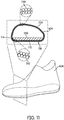
- FIGS. 11-12 illustrate schematic views of upper 604 with internal midsole structure 520 ( FIG. 11 ) and without midsole structure 520 ( FIG. 12 ). It will be understood that FIG. 12 is only intended for purposes of clarifying provisions of the exemplary designs. In particular, in some embodiments a midsole structure may not be removable and instead may be permanently disposed within an interior cavity of an upper.
- upper 604 maintains an approximately identical cross-sectional shape between the two configurations.
- the lower portion 710 of upper 604, associated with lower surface 712 and peripheral side surfaces 714 of upper 604 may not change in geometry or dimension even when midsole structure 520 is removed in the configuration of FIG. 12 .
- This consistent geometry for lower portion 710 may be due to the process of forming upper 604.
- tensile strands are braided around midsole structure 520 so that the resulting braided structure has a geometry that corresponds with the contours of midsole structure 520 in a relaxed or un-tensioned state of upper 604. For example, as shown in FIG.
- the strands 740 of the braided structure may be spaced apart by a similar amount to strands 742 in lower portion 710 of the braided structure, thereby indicating roughly even tension throughout upper 604 in this state.
- Such a configuration for upper 604 may be in contrast to alternative examples not falling within the scope of the invention, in which a midsole structure is inserted after the upper has been formed in an over-braiding process (or other braiding process).
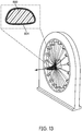
- a braided upper 804 may be formed on a last 800 without a midsole structure ( FIG. 13 ).
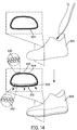
- a midsole structure 820 may be inserted into braided upper 804, as shown in FIG. 14 .
- braided upper 804 must stretch, especially at a lower portion 810, to accommodate the contours of midsole structure 820.
- FIG. 15 illustrates that if midsole structure 820 is removed from braided upper 804, braided upper 804 may revert to an earlier configuration where the geometry of lower portion 810 fails to retain the contours of midsole structure 820 (i.e., lower portion 810 no longer has a geometry corresponding to midsole structure 820). This may occur as upper 804 contracts with the removal of midsole structure 820.
- FIGS. 13-15 results in greater stretching in some portions of upper 804 due to the presence of midsole structure 820. Specifically, in lower portion 810 of upper 802 the strands 842 of the braided structure are spaced further apart than the strands 840 in top portion 839 of the braided structure, indicating an uneven tension throughout upper 802.
- the upper may be made more resilient and may also more easily accommodate additional tensions from ground contact forces, bending, etc.
Description
- The present embodiments relate generally to articles of footwear, and in particular to articles of footwear with uppers.
- Articles of footwear generally include an upper and one or more sole structures. The upper may be formed from a variety of materials that are stitched or adhesively bonded together to form a void within the footwear for comfortably and securely receiving a foot. The sole structures may include midsole structures that provide cushioning and shock absorption.
-
US 2013/305465 discloses a method for producing an upper part of a shoe, in particular of a sports shoe. -
CN 203369442 discloses the structure of a shoe lining sock. -
US 2014/189964 discloses shoes of automated process production and shoemaking method thereof. - In one aspect, a method of making an upper for an article of footwear comprises associating a midsole structure with a lower surface of a last, wherein a forefoot portion of the last has a cross-sectional area and a peripheral contour that bounds the cross-sectional area, and the last and midsole structure provide a combined peripheral contour, wherein a medial side portion of the peripheral contour has a first curvature, and a lateral side portion of the peripheral contour has a second curvature, wherein a medial side portion of the combined peripheral contour has a third curvature and a lateral side portion of the combined peripheral contour has a fourth curvature; and wherein the third curvature is substantially less than the first curvature, and/or wherein the fourth curvature is substantially less than the second curvature; the method further comprising inserting the last and the midsole structure through a braiding device while the midsole structure is associated with the lower surface of the last so as to form a braided structure around the last and the midsole structure, wherein the reduced curvature of the third curvature with respect to the first curvature and/or the reduced curvature of the fourth curvature with respect to the second curvature presents a smoother peripheral contour to the braiding device than would be presented by the last alone; and thereby forming the braided upper from the braided structure, wherein the midsole structure is disposed within an interior cavity of the braided upper.
- Other systems, methods, features and advantages of the embodiments will be, or will become, apparent to one of ordinary skill in the art upon examination of the following figures and detailed description. It is intended that all such additional systems, methods, features and advantages be included within this description and this summary, be within the scope of the embodiments, and be protected by the following claims.
- The embodiments can be better understood with reference to the following drawings and description. The components in the figures are not necessarily to scale, emphasis instead being placed upon illustrating the principles of the embodiments. Moreover, in the figures, like reference numerals designate corresponding parts throughout the different views.
-
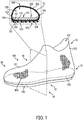
FIG. 1 is a schematic isometric view of an embodiment of an article of footwear including an enlarged cross-sectional view of a forefoot portion of the article of footwear; -
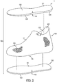
FIG. 2 is a schematic isometric exploded view of the article of footwear ofFIG. 1 ; -
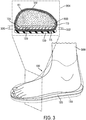
FIG. 3 is a schematic view of the article ofFIG. 1 with a foot inserted within an upper, including an enlarged cross-sectional view of a forefoot portion of the article of footwear and foot; -
FIG. 4 is a schematic isometric view of a step of temporarily attaching a midsole structure to a last, according to an embodiment; -
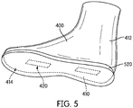
FIG. 5 is a schematic bottom isometric view of an embodiment of a midsole structure temporarily attached to a last; -
FIG. 6 is a schematic isometric view of the last and midsole structure ofFIG. 5 , including an enlarged cross-sectional view of the last and midsole structure; -
FIG. 7 is a schematic isometric view of an embodiment of a last and midsole structure inserted through a braiding device to form a braided structure over the last and midsole structure; -
FIG. 8 is a schematic isometric view of a braided upper being cut to form an opening according to an embodiment; -
FIG. 9 is a schematic view of a last being removed from a braided upper according to an embodiment; -
FIG. 10 is a schematic view of an outer sole structure being attached to a lower surface of a braided upper according to an embodiment; -
FIG. 11 is a schematic view of an embodiment of an upper with an interior midsole structure; -
FIG. 12 is a schematic view of the upper ofFIG. 11 with the midsole structure removed; -
FIGS. 13-15 illustrate schematic views of an alternative example, which does not fall within the scope of the invention, of an upper formed from a braided structure, where the upper is formed on a last and a midsole structure is inserted after the upper is formed on the last. -
FIG. 1 is an isometric view of an embodiment of an article offootwear 100. In the exemplary embodiment, article offootwear 100 has the form of an athletic shoe. However, in other embodiments, the provisions discussed herein for article offootwear 100 could be incorporated into various other kinds of footwear including, but not limited to: basketball shoes, hiking boots, soccer shoes, football shoes, sneakers, running shoes, cross-training shoes, rugby shoes, baseball shoes as well as other kinds of shoes. Moreover, in some embodiments, the provisions discussed herein for article offootwear 100 could be incorporated into various other kinds of non-sports related footwear, including, but not limited to: slippers, sandals, high heeled footwear, and loafers. - For purposes of clarity, the following detailed description discusses the features of article of
footwear 100, also referred to simply asarticle 100. However, it will be understood that other embodiments may incorporate a corresponding article of footwear (e.g., a right article of footwear whenarticle 100 is a left article of footwear) that may share some, and possibly all, of the features ofarticle 100 described herein and shown in the figures. - The embodiments may be characterized by various directional adjectives and reference portions. These directions and reference portions may facilitate in describing the portions of an article of footwear. Moreover, these directions and reference portions may also be used in describing sub-components of an article of footwear (e.g., directions and/or portions of a midsole structure, an outer sole structure, an upper or any other components).
- For consistency and convenience, directional adjectives are employed throughout this detailed description corresponding to the illustrated embodiments. The term "longitudinal" as used throughout this detailed description and in the claims refers to a direction extending a length of a component (e.g., an upper or sole component). In some cases, the longitudinal direction may extend from a forefoot portion to a heel portion of the component. Also, the term "lateral" as used throughout this detailed description and in the claims refers to a direction extending along a width of a component. In other words, the lateral direction may extend between a medial side and a lateral side of a component. Furthermore, the term "vertical" as used throughout this detailed description and in the claims refers to a direction generally perpendicular to a lateral and longitudinal direction. For example, in cases where an article is planted flat on a ground surface, the vertical direction may extend from the ground surface upward. Additionally, the term "inner" refers to a portion of an article disposed closer to an interior of an article, or closer to a foot when the article is worn. Likewise, the term "outer" refers to a portion of an article disposed further from the interior of the article or from the foot. Thus, for example, the inner surface of a component is disposed closer to an interior of the article than the outer surface of the component. This detailed description makes use of these directional adjectives in describing an article and various components of the article, including an upper, a midsole structure and/or an outer sole structure.
-
Article 100 may be characterized by a number of different regions or portions. For example,article 100 could include a forefoot portion, a midfoot portion, a heel portion and an ankle portion. Moreover, components ofarticle 100 could likewise comprise corresponding portions. Referring toFIG. 1 ,article 100 may be divided intoforefoot portion 10,midfoot portion 12 andheel portion 14.Forefoot portion 10 may be generally associated with the toes and joints connecting the metatarsals with the phalanges.Midfoot portion 12 may be generally associated with the arch of a foot. Likewise,heel portion 14 may be generally associated with the heel of a foot, including the calcaneus bone.Article 100 may also include an ankle portion 15 (which may also be referred to as a cuff portion). In addition,article 100 may includelateral side 16 andmedial side 18. In particular,lateral side 16 andmedial side 18 may be opposing sides ofarticle 100. Furthermore, bothlateral side 16 andmedial side 18 may extend throughforefoot portion 10,midfoot portion 12,heel portion 14 andankle portion 15. -
FIGS. 1-2 illustrate various components of article offootwear 100, including an upper 102, amidsole structure 120 and an outersole structure 130. For purposes of illustration, inFIG. 1 ,midsole structure 120 is shown in phantom in the isometric view ofarticle 100. - Upper 102 is a braided upper. More specifically, upper 102 comprises a braided structure having the form of an upper for an article of footwear. As used herein, the term "braided structure" (or braided component) refers to any structure that may be formed by intertwining three or more tensile elements to form the structure. Such tensile elements could include, but are not limited to: threads, yarns, strings, filaments, fibers, wires, cables as well as possibly other kinds of tensile elements. As used herein, tensile elements may describe generally elongated materials with lengths much greater than corresponding diameters. In other words, tensile elements may be approximately one-dimensional elements, in contrast to sheets or layers of textile materials that may generally be approximately two-dimensional (e.g., with thicknesses much less than their lengths and widths). As an example, upper 102 as seen in
FIGS. 1-2 is formed from a plurality of tensile elements 105 (e.g., yarns or strands of material) that are braided together to form a shape that is globally similar to the shape of a foot. For purposes of illustration, the individualtensile elements 105 are only shown in representative patches on upper 102 in the figures, but it may be understood that in at least some embodiments the entirety of upper 102 may comprisetensile elements 105 in a braided configuration. - Braiding can be used to form three-dimensional structures, by braiding strands of yarn over a form or a last. Strands of a braided structure, such as plurality of
tensile elements 105 of the exemplary embodiment, can be fabricated from fibers such as nylon, carbon, polyurethane, polyester, cotton, aramid (e.g., Kevlar®), polyethylene or polypropylene. These strands can be braided to form three-dimensional structures for a wide variety of applications. - Braided structures may be fabricated manually, or may be manufactured using automated braiding machinery, such as the machinery disclosed in
U.S. Patents Nos. 7,252,028 ;8,261,648 ;5,361,674 ;5,398,586 ; and4,275,638 . One exemplary manufacturing method, including the use of a radial braiding machine, is discussed below and shown inFIG. 7 . - Some embodiments may include braided uppers that extend beneath the foot, thereby providing 360 degree coverage at some regions of the foot. However, other embodiments need not include uppers that extend beneath the foot. In other embodiments, for example, a braided upper could have a lower periphery joined with a sole structure and/or sock liner. In the exemplary embodiment, upper 102 includes a closed lower portion 115 (see
FIGS. 1-3 ) that extends beneath a foot when the article is worn. - Embodiments could incorporate any of the braided structures, methods of making braided structure as well as any of the related provisions that are disclosed in
Bruce, U.S. Patent Publication Number 2015/0007451 , nowU.S. Patent Application Number 14/495,252 filed September 24, 2014 - Referring to
FIGS. 1-2 , upper 102 is seen to have anopening 107 that may receive a foot. Opening 107 may provide access to aninterior cavity 109 of upper 102. In the exemplary embodiment, upper 102 may have a bootie-like configuration without any additional fasteners. Depending on the material of the individualtensile strands 105, the exemplary embodiment may be configured to stretch fit over a foot without the need for additional fasteners. For example, usingtensile strands 105 with elastic properties may allow upper 102 to stretch over a foot and provide the needed amount of tension to keeparticle 100 on the foot. However, in other embodiments, upper 102 could incorporate fastening provisions including laces, straps, zippers or other kinds of fasteners that may help secure upper 102 around a foot. For example, other embodiments could utilize any of the fastening provisions for a braided upper that are disclosed in the Braided Upper application. -
Upper 102 may also be characterized by anouter surface 111, which is an exterior or exposed surface. In addition, upper 102 may include aninner surface 113 that is oppositeouter surface 111. -
Midsole structure 120 may generally incorporate various provisions associated with midsoles. In different embodiments, a midsole structure may be configured to provide cushioning, shock absorption, energy return, support, as well as possibly other provisions. -
Midsole structure 120 may comprise anexterior surface 122.Exterior surface 122 may be further comprised of afirst surface 124 and asecond surface 126 disposed opposite offirst surface 124. Here,first surface 124 may be a lower surface ofmidsole structure 120, whilesecond surface 126 may be an upper surface ofmidsole structure 120. Moreover,first surface 124 may include a first surface periphery 128 (e.g., a lower surface periphery), which extends around the boundary offirst surface 124. In some cases,first surface periphery 128 may be associated with the sides (or sidewalls) ofmidsole structure 120.Second surface 126 may extend from first surface periphery 128 (i.e.,second surface 126 is proximate to, or even continuous with, first surface periphery 128) and across the top side ofmidsole structure 120. - In different embodiments, the geometry of
midsole structure 120 could vary. In some embodiments,midsole structure 120 may have a two-dimensional geometry (e.g., a geometry in the plane spanned by the longitudinal and lateral directions) corresponding to a foot sole. In other embodiments, however, the geometry ofmidsole structure 120 could vary and could include various contours or features not associated with a foot sole. - In different embodiments, the dimensions of
midsole structure 120 could vary. In some embodiments,midsole structure 120 has a length approximately equal to a length of upper 102, asmidsole structure 120 may extend through the entirety ofinterior cavity 109 in the longitudinal direction. In other embodiments, howevermidsole structure 120 could have a length less than the length of upper 102. For example, in another embodiment, a midsole structure may only extend through the midfoot and heel portions of an article of footwear. In some embodiments,midsole structure 120 has a width approximately equal to a width of upper 102, asmidsole structure 120 may extend through the entire ofinterior cavity 109 in the lateral direction. However, in other embodiments, a midsole structure could only extend partially across the width of upper 102. - In some embodiments, the thickness of
midsole structure 120 may vary. In some embodiments, a midsole structure could be thicker than either an upper or an outer sole structure. In other embodiments, a midsole structure could be thinner than an upper and/or an outer sole structure. In some cases, a midsole structure could be equal in thickness to an upper and/or a sole structure. In the exemplary embodiment,midsole structure 120 has a thickness 141 that corresponds to the distance betweenfirst surface 124 andsecond surface 126 ofmidsole structure 120. In addition, upper 102 has athickness 142 and outersole structure 130 has athickness 143. Moreover, thickness 141 is greater thanthickness 142. Also, thickness 141 is greater thanthickness 143. This relatively greater thickness formidsole structure 120 may ensure thatmidsole structure 120 provides a larger degree of the shock absorption, cushioning and/or support than may be provided by the material structures of upper 102 and outersole structure 130. - A midsole structure may be formed from a variety of different materials. Exemplary materials that could be used in various embodiments include, but are not limited to: expanded rubber, foam rubber, various kinds of foams, polyurethane as well as possibly other materials. For example, in one embodiment, a midsole structure may be formed from a polymer foam material that attenuates ground reaction forces (i.e., provides cushioning) during walking, running, and other ambulatory activities. In various embodiments, midsole structures may also include fluid-filled chambers, plates, moderators, or other elements that further attenuate forces, enhance stability, or influence the motions of the foot, for example.
- Outer
sole structure 130 may include provisions for cushioning and/or may include provisions to enhance ground contact. In some embodiments, outersole structure 130 could primarily comprise an outsole. In such embodiments, the outsole forms a ground-contacting element of the footwear and is usually fashioned from a durable and wear-resistant rubber material that includes texturing to impart traction. In other embodiments, outersole structure 130 could also include cushioning provisions, including provisions associated with a midsole layer. - In the embodiments of
FIGS. 1-2 , outersole structure 130 may be characterized by afirst surface 131 and asecond surface 132 that is opposite offirst surface 131.First surface 131 may face inwardly, or towards upper 102, whilesecond surface 132 may face outwardly and may be a ground contacting surface. In some embodiments,second surface 132 could include provisions for enhancing traction with a ground surface such as treads, cleats, or other provisions. - As seen in
FIGS. 1-2 ,midsole structure 120 may be disposed within upper 102. Specifically,midsole structure 120 may be disposed withininterior cavity 109 of upper 102. In some cases,first surface 124 of midsole structure 120 (i.e., a lower surface) may be disposed againstinner surface 113 of upper 102. In other cases,first surface 124 ofmidsole structure 120 could be disposed against an intermediate layer, or may be otherwise spaced apart frominner surface 113 of upper 102. In either case,midsole structure 120 may be disposed closer toinner surface 113 of lower portion 115 (of upper 102) than toouter surface 111 oflower portion 115. Such an arrangement may be contrasted with other possible embodiments, where a midsole structure may be disposed externally to an upper and therefore disposed closer to an outer surface of the upper than to the inner surface of the upper. - Outer
sole structure 130 may be disposed againstouter surface 111 of upper 102. More specifically,first surface 131 outersole structure 130 may be disposed againstouter surface 111 onlower portion 115 of upper 102. Thus, whereasmidsole structure 120 may be disposed withininterior cavity 109 of upper 102, outersole structure 130 may be disposed outwardly on upper 102. Therefore,lower portion 115 of upper 102 may separate, or be disposed between,midsole structure 120 and outersole structure 130. - For purposes of clarity,
article 100 is shown without an inner liner or insole. In such an embodiment, a foot (or sock worn on the foot) may directly contact a surface of a midsole structure. For example, in some embodiments,second surface 126 ofmidsole structure 120 may be configured to receive and contact a foot directly. Such an exemplary configuration is shown inFIG. 3 , which shows a schematic view of afoot 300 inserted within article offootwear 100 along with a cross-sectional view of the article and foot as taken along avertical plane 304. In the configuration ofFIG. 3 ,foot 300 directly contactssecond surface 126 ofmidsole structure 120. In other embodiments, however, an optional insole or inner liner could be present between a foot andmidsole structure 120 whenarticle 100 is worn. Such a liner or insole may be disposed onsecond surface 126 ofmidsole structure 120. - Each component may be characterized by various material characteristics, including cushioning and compressibility. In various embodiments, the relative material characteristics of each component (e.g., upper 102,
midsole structure 120 and outer sole structure 130) could be varied. In one exemplary embodiment,midsole structure 120 may provide greater cushioning than either upper 102 or outersole structure 130. In addition, in one embodiment,midsole structure 120 may be more compressible than upper 102 andmidsole structure 120 may be more compressible than outersole structure 130. - The exemplary embodiment shown in
FIG. 3 shows the relative compressibility ofmidsole structure 120 relative to upper 102 and outersole structure 130. For example,midsole structure 120 is seen to compress under the weight offoot 300. Specifically,midsole structure 120 undergoes a change from anuncompressed thickness 320 to acompressed thickness 322. In contrast, upper 102 does not undergo any significant compression (e.g., change in thickness) atlower portion 115 under the weight offoot 300. Likewise, outersole structure 130 does not undergo any significant compression under the weight offoot 300. - In different embodiments, the degree of relative compressibility between
midsole structure 120 and other components ofarticle 100 can vary. In at least some embodiments,midsole structure 120 can undergo changes in thickness due to compressive forces (e.g., weight of foot or other ground contact forces) that are greater than the thickness of upper 102. In other words, the change in thickness (e.g., betweenuncompressed thickness 320 and compressed thickness 322) could be greater than a thickness of upper 102 (e.g.,thickness 142 as shown inFIG. 1 ). The degree of compression for a given force can vary according to factors including but not limited to: desired cushioning properties, midsole structure materials, midsole structure geometry as well as possibly other factors. Moreover, the compression ofmidsole structure 120 can be tuned to achieve optimal comfort and cushioning for a user. - In different embodiments, the attachment configurations of various components of
article 100 could vary. For example, in some embodiments,midsole structure 120 could be bonded or otherwise attached to an inner surface of upper 102. Such bonding or attachment could be accomplished using any known methods for bonding components of articles of footwear, including, but not limited to: adhesives, films, tapes, staples, stitching, or other methods. In some other embodiments, it is contemplated thatmidsole structure 120 may not be bonded or attached to upper 102, and instead could be free-floating. - Outer
sole structure 130 may be attached to upper 102 and/ormidsole structure 120. In some embodiments, outersole structure 130 could be attached directly to upper 102 using various attachment methods including, but not limited to: adhesives, tapes, staples, stitching, or other methods. In one embodiment, outersole structure 130 and/or upper 102 could include one or more heat bonding materials (e.g., thermoplastics or other resins) that may act as a bonding layer between outersole structure 130 and upper 102 when heated. - It is also contemplated that in at least some embodiments, outer
sole structure 130 may be attached directly tomidsole structure 120 through openings in the braided structure of upper 102 (e.g., through the spaces between strands). Thus, in at least some cases, an adhesive could be applied tofirst surface 131 of outersole structure 130 to bond outersole structure 130 to upper 102 and portions ofmidsole structure 120 simultaneously. In still other embodiments, outersole structure 130 and/ormidsole structure 120 could be made of heat bondable materials, so that after arranging outersole structure 130 andmidsole structure 120 relative to upper 102, heat may be applied to melt and bond outersole structure 130 andmidsole structure 120 to one another. In such cases, outersole structure 130 andmidsole structure 120 could be formed from bond compatible materials. Such an arrangement where outersole structure 130 is attached directly tomidsole structure 120 may help to anchor outersole structure 130 toarticle 100. - In order to form a braided upper with an internal midsole structure, a midsole structure is first temporarily attached to a last. The last with the temporarily attached midsole structure (also referred to collectively as a lasting assembly) is then fed through a braiding device (such as a radial braiding machine) to form a braided structure in the form of a braided upper around the last and midsole structure. Upon removal of the last, a braided upper with an internal midsole structure may be assembled with an outer sole structure to form an article of footwear, similar to
article 100 discussed above and shown inFIGS. 1-3 . -
FIGS. 4 and5 illustrate schematic steps in a process of making an article of footwear, such asarticle 100, according to an embodiment. Specifically,FIG. 4 illustrates an exploded isometric view of a last 400 (i.e., a footwear last),adhesive film elements 420 andmidsole structure 520.FIG. 5 illustrates a bottom isometric view ofmidsole structure 520 attached to last 400 usingadhesive film elements 420. It will be understood thatmidsole structure 520 may be similar tomidsole structure 120 of the embodiments shown inFIGS. 1-3 , and may optionally include some or all of the provisions discussed with respect tomidsole structure 120. - In
FIGS. 4 and5 , a process of temporarily attachingmidsole structure 120 to last 400 may be accomplished usingadhesive film elements 420. In particular,second surface 526 ofmidsole structure 120 may be temporarily bonded to a lower surface 410 (i.e., a sole surface) of last 400 by insertingadhesive film elements 420 betweensecond surface 126 andlower surface 410. - For purpose of clarity, only two film elements are shown, however in other embodiments any number, size, and arrangement of adhesive film elements could be used. In other embodiments, of course, any other method of temporarily fixing, attaching, bonding, adhering or otherwise temporarily joining a midsole structure with a last could be used. Exemplary methods include, but are not limited to, the use of adhesives, films, tapes, putties, as well as possibly other methods. It is contemplated that in some embodiments a last could be configured with a fastening element (such as a screw or other projection) and a midsole structure could be configured with provisions to receive the fastening element (such as a threaded hole to receive a screw). Thus, in some embodiments, a last and a midsole structure could be temporarily secured using some kind of mechanical fasteners, including, but not limited to: screws, bolts, hook and loop fasteners, clips, straps, as well as possibly other mechanical provisions. The method of temporarily joining a midsole structure and a last can be selected according to various factors including: last material and/or dimensions, midsole structure material and/or dimensions, as well as possibly other factors.
- For purposes of understanding the arrangement of
midsole structure 520 and last 400, last 400 may be characterized as comprising various different portions. For example, last 400 may include not only a lower surface 410 (i.e., the sole surface of last 400), but also anupper surface 412. As used herein, the term "upper surface" of a last refers to the area of the last surface that does not includelower surface 410, which is the surface of the last corresponding to the sole of a foot. Thus,upper surface 412 may generally include the medial side surface, the lateral side surface as well as the upper, forward and rearward surfaces of last 400.Upper surface 412 may generally extend to, or join, alower surface periphery 414 oflower surface 410. - As seen in
FIGS. 4 and5 ,midsole structure 520, when temporarily attached to last 400, covers onlylower surface 410 of last 400. In particular,upper surface 412 may be exposed whenmidsole structure 120 is temporarily attached to last 400. Such an arrangement may be in contrast, for example, to the placement of a bootie-like liner over last 400, which would tend to cover bothlower surface 410 andupper surface 412. In other words, the exemplary configuration of a component applied to last 400 is one where the component (a midsole structure) is applied only to a local portion of last 400, namely thelower surface 410 of last 400, rather than being uniformly applied over last 400 as in the case of a liner or other intermediate layer. - In order to enhance the operation of a braiding device, such as a radial braiding machine, it may be important to use last assemblies having smooth geometries. For purposes of clarity in characterizing the smoothness of these geometries, the term peripheral contour is used herein to denote the contour or boundary of a given cross-sectional area of a component. Additionally, contours, or lines that bound a given cross-sectional area, can be characterized as having curvature that may vary over different sections of the contour. In the present discussion, the curvature of a given section of a contour may be described by a radius of curvature and the curvature of different sections can be compared according to the differences in their radii of curvature.
-
FIG. 6 illustrates an isometric view oflasting assembly 500, comprising last 400 andmidsole structure 520, including an enlarged cross-sectional view of a portion oflasting assembly 500. In particular, a cross-sectional view offorefoot portion 430 of last 400 is shown taken along aplane 450. As seen inFIG. 6 ,forefoot portion 430 has across-sectional area 425 and aperipheral contour 427 that bounds thecross-sectional area 425.Peripheral contour 427 may further be comprised of atop portion 432, abottom portion 434, amedial side portion 436 and alateral side portion 438. - As shown in
FIG. 6 ,medial side portion 436 andlateral side portion 438 may be representative of portions of the exterior surface of last 400 where the curvature is relatively high and non-constant. For example,medial side portion 436 has a first curvature, represented inFIG. 6 by first radius ofcurvature 460. Additionally,lateral side portion 438 has a second curvature, represented inFIG. 6 by second radius ofcurvature 462. - As shown in
FIG. 6 , when temporarily attached to last 400,midsole structure 520 may help reduce regions of high curvature. InFIG. 6 , last 400 and midsole structure are seen to provide a combinedperipheral contour 470. The combinedperipheral contour 470 represents the peripheral contour that will be presented to a braiding machine during formation of a braided upper. In this case, amedial side portion 476 of combinedperipheral contour 470 has a third radius ofcurvature 464 and alateral side portion 478 of combinerperipheral contour 470 has a fourth radius ofcurvature 466. - As clearly seen in
FIG. 6 , the geometry of combinedperipheral contour 470 is different than the geometry of the last 400. For example, combinedperipheral contour 470 is significantly less curved on the medial and lateral sides of last 400 andmidsole structure 520. Specifically,third curvature 464 is substantially less thanfirst curvature 460 on the medial sides of last 400 andmidsole structure 520, and/orfourth curvature 466 is substantially less thansecond curvature 462 on the lateral sides of last 400 andmidsole structure 520. Because of this reduced curvature on the lateral and medial sides, last 400 andmidsole structure 120 together present a smoother peripheral contour (e.g., a cross-sectional area with a smoother boundary) to a braiding machine than would be presented by last 400 alone. - It will be understood that the curvature of last 400 may vary over different portions from the curvature depicted for
forefoot portion 430. It may be appreciated that in other portions where last 400 may have high curvature the addition ofmidsole structure 120 may also help present a smoother contoured periphery to the braiding machine. -
FIG. 7 illustrates a step of inserting lasting assembly 500 (i.e., last 400 and midsole structure 520) through abraiding device 522. In some embodiments,braiding device 522 may include provisions for over-braiding strands onto a lasting assembly. In the configuration shown inFIG. 7 ,braiding device 522 includesspools 502 withthreads 504 that may be over-braided onto last 400 andmidsole structure 520 as these components are inserted through acentral braiding area 523 ofbraiding device 522. - In some embodiments, lasting
assembly 500 may be manually fed throughbraiding device 522 by a human operator. In other embodiments, a continuous last feeding system can be used to feedlasting assembly 500 throughbraiding device 522. The present embodiments could make use of any of the methods and systems for forming a braided upper disclosed in the Braided Upper application. - As shown in
FIG. 7 , as lastingassembly 500 is fed throughbraiding device 522, abraided structure 602 is formed around last 400 andmidsole structure 120. In this case, braidedstructure 602 forms a continuously braided upper that conforms to last 400 andmidsole structure 120, and therefore has the approximate geometry of the combination of last 400 andmidsole structure 120. - In some embodiments, methods of braiding may also include provisions for holding and/or feeding articles through
braiding device 522. For example, some embodiments may include support platforms (not shown) that can facilitate feeding articles throughbraiding device 522. Generally, any systems known in the art for feeding objects through a braiding machine could be used. In some embodiments, a conveyor system could be used to automatically move a footwear last throughbraiding device 522. In some other embodiments, each footwear last could be manually inserted throughbraiding device 522. - As seen in
FIG. 7 , the exemplary method provides a generally rounded cross-sectional shape without any regions of high curvature that might interfere with the over-braiding process. -
FIGS. 8-9 illustrate a schematic view of a step of cutting abraided structure 602 and removing last 400. In some cases, as schematically shown inFIGS. 8-9 , after formingbraided footwear structure 602, asection 608 of braidedfootwear structure 602 can be cut or otherwise removed to form anopening 610 inbraided footwear structure 602. In some cases, last 400 can be removed from opening 610, which may further serve as an opening for a foot. - Although not shown here, some embodiments can also include provisions for assembling trim, overlay, or other components or portions of material for assembly with a braided structure. As used herein, the term "overlay" refers to any material layer that could be disposed over a layer of braided material, including braided material for an upper. Overlays could be comprised of any kinds of materials and may be configured with a variety of different characteristics (e.g., stretch, elasticity, density, weight, durability, breathability, etc.). Also, overlays could have any dimensions and could be configured to cover some portions and/or all portions of a braided structure. Overlays could be disposed on an interior surface of a braided structure and/or an exterior surface of a braided structure. Embodiments could use any of the overlays, and/or methods for attaching overlays to braided structure, disclosed in Bruce,
U.S. Patent Publication Number 2014/0373389 , nowU.S. Patent Application Number 14/163,438, filed January 24, 2014 -
FIG. 10 illustrates an isometric view of an embodiment of a braided upper 604 formed from braided structure 602 (incorporating internal midsole structure 520) being assembled with an outersole structure 650. Here,surface 652 of outersole structure 650 may be temporarily bonded to a lower surface 605 (i.e., a sole surface) of braided upper 604 using an adhesive 660 betweensurface 652 andlower surface 605. In other embodiments, of course, any other method of temporarily fixing, attaching, bonding, adhering or otherwise temporarily joining an outer sole structure with an upper could be used. Exemplary methods include, but are not limited to, the use of adhesives, films, tapes, as well as possibly other methods. Still other embodiments may not include an outer sole structure. Further, in other embodiments, additional sole components or layers could be incorporated between an outer sole structure and a braided upper. - Embodiments could use any methods for manufacturing braided articles including uppers with internal midsoles. In particular, embodiments could use any of the methods of braiding uppers, forming and attaching overlay structures (using 3D printing and high frequency welding) as well any other methods, systems or provisions disclosed in
Bruce, U.S. Patent Publication Number 2016/0166011 , filed asU.S. Patent Application Number 14/565,582 on December 10, 2014 -
FIGS. 11-12 illustrate schematic views of upper 604 with internal midsole structure 520 (FIG. 11 ) and without midsole structure 520 (FIG. 12 ). It will be understood thatFIG. 12 is only intended for purposes of clarifying provisions of the exemplary designs. In particular, in some embodiments a midsole structure may not be removable and instead may be permanently disposed within an interior cavity of an upper. - As seen by comparing the enlarged cross-sectional views in
FIG. 11 andFIG. 12 , upper 604 maintains an approximately identical cross-sectional shape between the two configurations. Specifically, thelower portion 710 of upper 604, associated withlower surface 712 and peripheral side surfaces 714 of upper 604, may not change in geometry or dimension even whenmidsole structure 520 is removed in the configuration ofFIG. 12 . This consistent geometry forlower portion 710 may be due to the process of forming upper 604. Specifically, tensile strands are braided aroundmidsole structure 520 so that the resulting braided structure has a geometry that corresponds with the contours ofmidsole structure 520 in a relaxed or un-tensioned state of upper 604. For example, as shown inFIG. 12 , at atop portion 739 of upper 604 thestrands 740 of the braided structure may be spaced apart by a similar amount tostrands 742 inlower portion 710 of the braided structure, thereby indicating roughly even tension throughout upper 604 in this state. - Such a configuration for upper 604 may be in contrast to alternative examples not falling within the scope of the invention, in which a midsole structure is inserted after the upper has been formed in an over-braiding process (or other braiding process). For example, in an alternative example shown in
FIGS. 13-15 , a braided upper 804 may be formed on a last 800 without a midsole structure (FIG. 13 ). Next, once braided upper 804 has been formed (and last 800 removed), amidsole structure 820 may be inserted into braided upper 804, as shown inFIG. 14 . In this case, braided upper 804 must stretch, especially at alower portion 810, to accommodate the contours ofmidsole structure 820. Such stretching may result in increased tension atlower portion 810 of braided upper 804, which is tension within upper 804 caused by the presence ofmidsole structure 820. Finally,FIG. 15 illustrates that ifmidsole structure 820 is removed from braided upper 804, braided upper 804 may revert to an earlier configuration where the geometry oflower portion 810 fails to retain the contours of midsole structure 820 (i.e.,lower portion 810 no longer has a geometry corresponding to midsole structure 820). This may occur as upper 804 contracts with the removal ofmidsole structure 820. - In contrast to the embodiment of
FIGS. 11-12 , the example shown inFIGS. 13-15 results in greater stretching in some portions of upper 804 due to the presence ofmidsole structure 820. Specifically, inlower portion 810 of upper 802 thestrands 842 of the braided structure are spaced further apart than thestrands 840 intop portion 839 of the braided structure, indicating an uneven tension throughout upper 802. - By forming an upper so that the upper geometry accommodates a midsole structure without stretching, as occurs in the exemplary embodiments shown in
FIGS. 1-12 , the upper may be made more resilient and may also more easily accommodate additional tensions from ground contact forces, bending, etc. - While various embodiments have been described, the description is intended to be exemplary, rather than limiting and it will be apparent to those of ordinary skill in the art that many more embodiments and implementations are possible that are within the scope of the embodiments. Any feature of any embodiment may be used in combination with or substituted for any other feature or element in any other embodiment unless specifically restricted. Accordingly, the embodiments are not to be restricted except in light of the attached claims. Also, various modifications and changes may be made within the scope of the attached claims.
Claims (13)
- A method of making a braided upper (102) for an article of footwear (100), comprising:associating a midsole structure (120, 520) with a lower surface (410) of a last (400),wherein a forefoot portion (430) of the last (400) has a cross-sectional area (425) and a peripheral contour (427) that bounds the cross-sectional area (425), and the last (400) and midsole structure (120, 520) provide a combined peripheral contour (470),wherein a medial side portion (436) of the peripheral contour (427) has a first curvature (460), and a lateral side portion (438) of the peripheral contour (427) has a second curvature (462),wherein a medial side portion (476) of the combined peripheral contour (470) has a third curvature (464) and a lateral side portion (478) of the combined peripheral contour (470) has a fourth curvature (466); andwherein the third curvature (464) is substantially less than the first curvature (460), and/or wherein the fourth curvature (466) is substantially less than the second curvature (462);the method further comprising inserting the last (400) and the midsole structure (120, 520) through a braiding device (522) while the midsole structure (120, 520) is associated with the lower surface (410) of the last (400) so as to form a braided structure (602) around the last (400) and the midsole structure (120, 520), wherein the reduced curvature of the third curvature (464) with respect to the first curvature (460) and/or the reduced curvature of the fourth curvature (466) with respect to the second curvature (462) presents a smoother peripheral contour to the braiding device (522) than would be presented by the last (400) alone; andthereby forming the braided upper (102) from the braided structure (602), wherein the midsole structure (120, 520) is disposed within an interior cavity (109) of the braided upper (102).
- The method according to claim 1, wherein associating the midsole structure (120, 520) with the lower surface (410) of the last (400) includes temporarily bonding the midsole structure (120, 520) to the lower surface (410).
- The method according to claim 2, wherein the method includes applying a bonding material between the midsole structure (120, 520) and the lower surface (410).
- The method according to claim 3, wherein the bonding material is an adhesive film (420).
- The method according to claim 3, wherein the bonding material is a liquid adhesive layer.
- The method according to claim 1, wherein the midsole (120, 520) has a first thickness (141), wherein the braided upper (102) has a second thickness (142) and wherein the first thickness (141) is greater than the second thickness (142).
- The method according to claim 1, wherein the lower surface (410) of the last (400) includes a lower surface periphery (414), wherein the last (400) includes an upper surface (412) extending to the lower surface periphery (414), and wherein the upper surface (412) is exposed while the midsole structure (120, 520) is temporarily attached to the last (400).
- The method according to claim 1, wherein the method includes removing the last (400) from the braided upper (102).
- The method according to claim 1, wherein the braiding device (522) is a radial braiding machine.
- A method of making an article of footwear (100), comprising:
the method of making an upper according to claim 1, the method of making the article of footwear further comprising:removing the last (400) from the braided upper (102);attaching an outer sole structure (130) to a lower portion (115) of the braided upper (102), the outer sole structure (130) including a ground engaging surface (132); andthereby forming the article of footwear (100). - The method according to claim 10, wherein the midsole structure (120, 520) is made of a first material, the braided upper (102) is made of a second material and the outer sole structure (130) is made of a third material, and wherein the first material is different from the second material and the third material is different from the second material.
- The method according to claim 11, wherein the first material is different from the third material.
- The method according to claim 11, wherein the first material is more compressible than the second material.
Applications Claiming Priority (2)
| Application Number | Priority Date | Filing Date | Title |
|---|---|---|---|
| US14/565,598 US10674791B2 (en) | 2014-12-10 | 2014-12-10 | Braided article with internal midsole structure |
| PCT/US2015/055868 WO2016093954A1 (en) | 2014-12-10 | 2015-10-16 | Braided article with internal midsole structure |
Publications (2)
| Publication Number | Publication Date |
|---|---|
| EP3229630A1 EP3229630A1 (en) | 2017-10-18 |
| EP3229630B1 true EP3229630B1 (en) | 2019-07-17 |
Family
ID=54352534
Family Applications (1)
| Application Number | Title | Priority Date | Filing Date |
|---|---|---|---|
| EP15785032.2A Active EP3229630B1 (en) | 2014-12-10 | 2015-10-16 | Braided article with internal midsole structure |
Country Status (10)
| Country | Link |
|---|---|
| US (1) | US10674791B2 (en) |
| EP (1) | EP3229630B1 (en) |
| JP (1) | JP6730282B2 (en) |
| KR (1) | KR101970906B1 (en) |
| CN (1) | CN106998844B (en) |
| AU (1) | AU2015361198B2 (en) |
| CA (1) | CA2970267A1 (en) |
| MX (1) | MX2017007375A (en) |
| TW (2) | TW201728275A (en) |
| WO (1) | WO2016093954A1 (en) |
Families Citing this family (30)
| Publication number | Priority date | Publication date | Assignee | Title |
|---|---|---|---|---|
| CA3020031A1 (en) | 2013-06-25 | 2014-12-31 | Nike Innovate C.V. | Article of footwear with braided upper |
| US20140373389A1 (en) * | 2013-06-25 | 2014-12-25 | Nike, Inc. | Braided Upper With Overlays For Article Of Footwear |
| US10863794B2 (en) | 2013-06-25 | 2020-12-15 | Nike, Inc. | Article of footwear having multiple braided structures |
| US10674791B2 (en) | 2014-12-10 | 2020-06-09 | Nike, Inc. | Braided article with internal midsole structure |
| US9668544B2 (en) | 2014-12-10 | 2017-06-06 | Nike, Inc. | Last system for articles with braided components |
| US20160345675A1 (en) | 2015-05-26 | 2016-12-01 | Nike, Inc. | Hybrid Braided Article |
| US10555581B2 (en) | 2015-05-26 | 2020-02-11 | Nike, Inc. | Braided upper with multiple materials |
| US11103028B2 (en) | 2015-08-07 | 2021-08-31 | Nike, Inc. | Multi-layered braided article and method of making |
| USD773790S1 (en) * | 2016-04-14 | 2016-12-13 | Skechers U.S.A., Inc. Ii | Shoe midsole periphery |
| USD792067S1 (en) * | 2016-04-14 | 2017-07-18 | Skechers U.S.A., Inc. Ii | Shoe midsole periphery |
| USD781543S1 (en) * | 2016-06-03 | 2017-03-21 | Skechers U.S.A., Inc. Ii | Shoe midsole periphery |
| USD773791S1 (en) * | 2016-06-03 | 2016-12-13 | Skechers U.S.A., Inc. Ii | Shoe midsole periphery |
| US10806210B2 (en) | 2017-05-31 | 2020-10-20 | Nike, Inc. | Braided articles and methods for their manufacture |
| US11202483B2 (en) | 2017-05-31 | 2021-12-21 | Nike, Inc. | Braided articles and methods for their manufacture |
| US11051573B2 (en) | 2017-05-31 | 2021-07-06 | Nike, Inc. | Braided articles and methods for their manufacture |
| DE102017210821A1 (en) | 2017-06-27 | 2018-12-27 | Adidas Ag | Specially-designed braided hose |
| US10716354B2 (en) | 2017-07-13 | 2020-07-21 | Under Armour, Inc. | Braided article and method of making |
| US11730231B2 (en) | 2017-08-31 | 2023-08-22 | Nike, Inc. | Sole structure of an article of footwear and related methods |
| US11937664B2 (en) * | 2017-08-31 | 2024-03-26 | Nike, Inc. | Sole structure of an article of footwear and related methods |
| DE102018200453A1 (en) | 2018-01-12 | 2019-07-18 | Adidas Ag | Custom-designed shoe or custom-designed apparel |
| CN108903128A (en) * | 2018-07-05 | 2018-11-30 | 清远市广硕鞋业有限公司 | Shoe body structure and its preparation method |
| CN112804905A (en) | 2018-08-08 | 2021-05-14 | 耐克创新有限合伙公司 | Midsole structure for an article of footwear comprising a mesh |
| CN112702932B (en) * | 2018-08-28 | 2022-06-17 | 耐克创新有限合伙公司 | Method for forming a footwear midsole |
| US20210177095A1 (en) * | 2019-12-17 | 2021-06-17 | Under Armour, Inc. | Article of Footwear with Braided Upper |
| US11439206B2 (en) * | 2019-12-17 | 2022-09-13 | Under Armour, Inc. | Method of making an article of footwear with braided upper |
| US20210282501A1 (en) * | 2020-03-11 | 2021-09-16 | Adidas Ag | Footwear having covered midsole and methods of manufacturing the same |
| CN115334926A (en) | 2020-03-29 | 2022-11-11 | 耐克创新有限合伙公司 | Sole structure for an article of footwear |
| CN111436713B (en) * | 2020-04-03 | 2021-09-03 | 福建祺烽新材料科技有限公司 | Method for producing woven shoes |
| US11910885B2 (en) * | 2020-10-05 | 2024-02-27 | Puma SE | Article of footwear incorporating winding elements |
| JP2022127292A (en) * | 2021-02-19 | 2022-08-31 | 株式会社アシックス | Shoe |
Family Cites Families (391)
| Publication number | Priority date | Publication date | Assignee | Title |
|---|---|---|---|---|
| US621922A (en) | 1899-03-28 | Richard edward kelsall | ||
| US578294A (en) | 1897-03-02 | Detachable waistband | ||
| US329739A (en) | 1885-11-03 | Ernst henkels | ||
| USRE21392E (en) | 1940-03-12 | Woven shoe | ||
| US165941A (en) | 1875-07-27 | Improvement in lace-machines | ||
| US1687643A (en) | 1928-10-16 | Jacob s | ||
| US1318888A (en) | 1919-10-14 | Planograpk co | ||
| US509241A (en) | 1893-11-21 | James w | ||
| US376372A (en) | 1888-01-10 | Manufacture of woolen boots | ||
| US586137A (en) | 1897-07-13 | Carl friedeich medger | ||
| US1182325A (en) | 1915-11-12 | 1916-05-09 | Vinco Sedmak | Shoe. |
| GB192305A (en) | 1922-03-03 | 1923-02-01 | Charles Wilfred Birkin | Improvements in the manufacture of lace |
| US1597934A (en) | 1922-10-10 | 1926-08-31 | Edwin B Stimpson | Stocking |
| US1527344A (en) | 1922-12-27 | 1925-02-24 | Max Henkels | Lace produced on the single-thread lace-braiding machine |
| US1583273A (en) | 1923-01-06 | 1926-05-04 | Max Henkels | Machine-braided torchon lace and method of making the same |
| US1538160A (en) | 1924-06-05 | 1925-05-19 | Max Henkels | Machine-braided lace |
| US1540903A (en) | 1924-07-28 | 1925-06-09 | Santoyo Frank | Shoe |
| US1554325A (en) | 1924-10-22 | 1925-09-22 | Max Henkels | Machine-braided lace |
| US1600621A (en) | 1925-10-02 | 1926-09-21 | Jr Tycho Buek | Shoe and process of making same |
| FR613280A (en) | 1925-10-06 | 1926-11-13 | Alb Et E Henkels G M B H | Process for making bobbin lace patterns for bedspreads, curtains, etc. |
| US1663319A (en) | 1927-03-09 | 1928-03-20 | Anthony Richard Kuhns | Shoe and method for forming the same |
| US1713307A (en) | 1928-12-07 | 1929-05-14 | Karl A Stritter | Shoe |
| US1717183A (en) | 1929-02-23 | 1929-06-11 | Brenner Edward | Shoe and method of making and ornamenting the same |
| US1803554A (en) | 1930-03-26 | 1931-05-05 | Harold M Knilans | Athletic shoe |
| US1877080A (en) | 1930-05-28 | 1932-09-13 | Teshima Isago | Wading overshoe |
| US1949318A (en) | 1930-05-30 | 1934-02-27 | Markowsky Fritz | Footwear |
| US1832691A (en) | 1930-07-19 | 1931-11-17 | Irwin W David | Footwear |
| US1828320A (en) | 1931-06-17 | 1931-10-20 | Claude H Daniels | Boot or shoe and method of making same |
| US1864254A (en) | 1932-03-24 | 1932-06-21 | Golo Slipper Company Inc | Sandal |
| US1887643A (en) | 1932-04-02 | 1932-11-15 | Narrow Fabric Company | Lace braid and method of manufacturing same |
| US2001293A (en) | 1934-02-10 | 1935-05-14 | Wilson Wallace | Knitted stocking foot protector |
| GB430805A (en) | 1934-12-17 | 1935-06-25 | Emil Krenzler | Improvements in or relating to elastic braided work containing rubber threads and method of and means for making same |
| US2022350A (en) | 1935-04-11 | 1935-11-26 | Narrow Fabric Company | Braid elastic fabric and method of making the same |
| US2091215A (en) | 1935-08-28 | 1937-08-24 | Price William Harold | Lace and method of producing the same |
| US2165092A (en) | 1935-10-08 | 1939-07-04 | Claude H Daniels | Shoe vamp |
| GB477556A (en) | 1936-07-07 | 1938-01-03 | William Harold Frice | Improvements in or relating to vamps or uppers for sandals, shoes and similar footwear and in the production thereof |
| US2147197A (en) | 1936-11-25 | 1939-02-14 | Hood Rubber Co Inc | Article of footwear |
| US2144689A (en) | 1937-01-27 | 1939-01-24 | Us Rubber Co | Fabric for shoes |
| US2162472A (en) | 1937-05-12 | 1939-06-13 | Riverside Company | Machine for closing and sealing articles in cellulose tubes |
| BE426458A (en) | 1937-08-07 | 1938-03-31 | ||
| US2161472A (en) | 1938-12-30 | 1939-06-06 | Hurwit Sol | Woven shoe |
| US2188640A (en) | 1939-10-10 | 1940-01-30 | Liberty Lace And Netting Works | Lace fabric |
| US2271888A (en) | 1940-01-09 | 1942-02-03 | Vulcan Corp | Method for decorating lasts |
| DE726634C (en) | 1940-01-16 | 1942-10-17 | Carl Friedrich | Method and device for the production of shoe uppers from wickerwork |
| US2311959A (en) | 1941-03-10 | 1943-02-23 | Nurk John | Shoe construction |
| US2382559A (en) | 1943-11-16 | 1945-08-14 | David D Goldstein | Footwear and method of its manufacture |
| US2412808A (en) | 1945-01-03 | 1946-12-17 | David D Goldstein | Sandal |
| US2521072A (en) | 1945-07-21 | 1950-09-05 | Stanley P Lovell | Lasts |
| FR1012719A (en) | 1950-02-13 | 1952-07-16 | Manufacture of braided shoes on planks | |
| US2586045A (en) | 1950-06-23 | 1952-02-19 | Hoza John | Sock-type footwear |
| US2679117A (en) | 1950-10-03 | 1954-05-25 | Ripon Knitting Works | Article of footwear and method of making the same |
| US2641004A (en) | 1950-12-26 | 1953-06-09 | David V Whiting | Method for producing knitted shoe uppers of shrinkable yarn |
| US2675631A (en) | 1951-02-13 | 1954-04-20 | Doughty John Carr | Footwear article of the slipper-sock type |
| USD164847S (en) | 1951-07-30 | 1951-10-16 | Jean Dronoff | Shoe |
| US2701887A (en) | 1951-11-20 | 1955-02-15 | James H Nolan | Method of temporarily attaching insoles to lasts |
| US2617129A (en) | 1952-07-21 | 1952-11-11 | Delaware Res & Dev Corp | Shoe last |
| BE534089A (en) | 1954-01-11 | |||
| DE1140107B (en) | 1956-07-02 | 1962-11-22 | Josef Haberstroh | Shoe with a front leaf made of wickerwork |
| US3052904A (en) * | 1961-11-03 | 1962-09-11 | Bain Corp | Method for detachably securing an insole to the bottom of a shoe last |
| CH512209A (en) | 1962-11-18 | 1971-09-15 | Duo Internat Inc | Method of manufacturing the upper of a shoe and device for its implementation |
| US3282757A (en) | 1962-12-14 | 1966-11-01 | Structural Fibers | Method of making a filament reinforced pressure vessel |
| GB1083849A (en) | 1963-11-26 | 1967-09-20 | British United Shoe Machinery | Improvements in or relating to the stiffening of shoes |
| US3257677A (en) * | 1964-08-19 | 1966-06-28 | Batchelder Rubico Inc | Releasable attaching device |
| US3397847A (en) | 1966-08-31 | 1968-08-20 | Herbert V. Thaden | Elbow winding apparatus |
| US3474478A (en) | 1968-05-09 | 1969-10-28 | Batchelder Rubico Inc | Stitched adhesive tape releasable attaching method |
| US3586058A (en) | 1968-09-25 | 1971-06-22 | Mc Donnell Douglas Corp | Hollow bodies and method of fabricating the same |
| GB1299353A (en) | 1969-02-06 | 1972-12-13 | Stephen Gulyas | Thermo-insulated footwear |
| US3745600A (en) | 1969-03-07 | 1973-07-17 | J Rubico | Method of making shoes over sheathed last utilizing a lasting element |
| US3525110A (en) | 1969-03-07 | 1970-08-25 | Batchelder Rubico Inc | Method of making shoes over sheathed lasts |
| US3619838A (en) | 1970-05-06 | 1971-11-16 | Compo Ind Inc | Last with detachable heel core |
| US3805667A (en) | 1970-08-21 | 1974-04-23 | Columbian Rope Co | Braided rope |
| US3821827A (en) * | 1972-08-25 | 1974-07-02 | M Nadler | Stitchdown footwear and method of manufacture |
| JPS51107964U (en) | 1975-02-27 | 1976-08-28 | ||
| US4149248A (en) | 1975-12-23 | 1979-04-10 | Varian Associates, Inc. | Apparatus and method for reconstructing data |
| DE2701359A1 (en) | 1976-03-12 | 1977-09-15 | James R Hanrahan | METHOD OF MANUFACTURING FOOTWEAR |
| US4232458A (en) | 1978-03-13 | 1980-11-11 | Wheelabrator Corp. Of Canada | Shoe |
| US4194249A (en) | 1979-02-14 | 1980-03-25 | Thorneburg Hosiery Co., Inc. | Jogging and running athletic sock |
| US4222183A (en) | 1979-10-29 | 1980-09-16 | Haddox Billy J | Athletic shoe |
| US4275638A (en) | 1980-03-10 | 1981-06-30 | Deyoung Simon A | Braiding machine |
| US4351889A (en) | 1980-04-28 | 1982-09-28 | Koehler Manufacturing Company | Tubular bodies for use in a positive plate of a lead-acid storage battery |
| US4341097A (en) | 1980-07-21 | 1982-07-27 | Kayser-Roth Hosiery, Inc. | Hosiery article with a reinforced toe with varying density |
| IT8121560V0 (en) | 1981-04-23 | 1981-04-23 | Nuova Zarine Costruzione Macch | FOOTWEAR WITH UPPER ZONALLY COVERED BY SYNTHETIC MATERIAL INJECTED STABLY JOINED TO THE CANVAS. |
| US4394803A (en) | 1981-06-10 | 1983-07-26 | Polsam, Inc. | Elasticized overlay |
| JPS5913849Y2 (en) | 1981-09-30 | 1984-04-24 | 株式会社 サカシタ | covering |
| US4629650A (en) | 1982-12-30 | 1986-12-16 | Asahi Kasei Kogyo Kabushiki Kaisha | Process for producing molded thermoplastic resin |
| US4519290A (en) | 1983-11-16 | 1985-05-28 | Thiokol Corporation | Braided preform for refractory articles and method of making |
| US4587749A (en) | 1984-11-28 | 1986-05-13 | Remo Berlese | Vented motorcycle boot |
| US4591155A (en) | 1985-02-20 | 1986-05-27 | Yutaka Adachi | Method of making hockey sticks |
| US4662088A (en) | 1985-04-29 | 1987-05-05 | Autry Industries, Inc. | Achilles tendon protection and support pad |
| US4640027A (en) | 1985-10-22 | 1987-02-03 | Remo Berlese | Motorcycle boot with positive air circulation |
| KR900008808B1 (en) | 1985-12-20 | 1990-11-30 | 가부시기가이샤 다나사와 핫고오샤 | Plastics shaping mold and method of preparing mold |
| US4719837A (en) | 1986-04-17 | 1988-01-19 | E. I. Dupont De Nemours And Company | Complex shaped braided structures |
| US4848745A (en) | 1986-06-04 | 1989-07-18 | Phillips Petroleum Company | Fiber reinforced article |
| JPS6325004U (en) | 1986-07-31 | 1988-02-18 | ||
| CN86209002U (en) | 1986-11-12 | 1987-10-31 | 天津市童鞋厂 | Thread weaving sandals |
| US4847063A (en) | 1987-12-02 | 1989-07-11 | Fiber Materials, Inc. | Hollow composite body having an axis of symmetry |
| US4857124A (en) | 1987-12-14 | 1989-08-15 | Plas/Steel Products, Inc. | Fiber-reinforced plastic strut connecting link |
| US4992313A (en) | 1987-12-14 | 1991-02-12 | Shobert James P | Fiber-reinforced plastic strut connecting link |
| US4976812A (en) | 1988-02-02 | 1990-12-11 | E. I. Du Pont De Nemours And Company | In-line consolidation of braided structures |
| USD315823S (en) | 1988-02-29 | 1991-04-02 | Sidi Sport S.A.S. Di Dino Signori & C. | Cross-country motorcyclist's boot |
| IT213697Z2 (en) | 1988-02-29 | 1990-01-22 | Signori Dino Sidi Sport | IMPROVEMENT IN THE BOOTS OF THE TYPE CALLED BY MOTOCROSS. |
| US4916997A (en) | 1988-05-09 | 1990-04-17 | Airfoil Textron Inc. | Method for making 3D fiber reinforced metal/glass matrix composite article |
| US5001961A (en) | 1988-05-09 | 1991-03-26 | Airfoil Textron Inc. | Braided preform |
| IT1230176B (en) | 1988-12-06 | 1991-10-18 | Superga Spa | GYMNASTIC SHOE WITH PERFECTED UPPER |
| US4885973A (en) | 1988-12-14 | 1989-12-12 | Airfoil Textron Inc. | Method of making composite articles |
| US5067525A (en) | 1988-12-28 | 1991-11-26 | Three-D Composites Research Corporation | Three-dimensional fabric woven by interlacing threads with rotor driven carriers |
| US5121329A (en) | 1989-10-30 | 1992-06-09 | Stratasys, Inc. | Apparatus and method for creating three-dimensional objects |
| US4974275A (en) | 1989-12-04 | 1990-12-04 | Backes James G | Method of manufacture of snowshoes |
| CS25891A2 (en) | 1990-02-09 | 1991-09-15 | Donald Richardson | Braided reinforcement of pipe lines especially hoses and method and equipment for its production |
| JPH0734885B2 (en) | 1990-04-16 | 1995-04-19 | 横浜ゴム株式会社 | Adhesive coating method and adhesive coating device in hose manufacturing process |
| US5287790A (en) | 1990-05-11 | 1994-02-22 | Murata Kikai Kabushiki Kaisha | Method and apparatus for braiding in two braiding regions |
| US5396829A (en) | 1990-05-11 | 1995-03-14 | Murata Kikai Kabushiki Kaisha | Apparatus for multiple layer tubular braiding |
| US5398586A (en) | 1990-08-25 | 1995-03-21 | Murata Kikai Kabushiki Kaisha | Braided structure forming method |
| JPH0674542B2 (en) | 1990-08-25 | 1994-09-21 | 村田機械株式会社 | Composition method of braid structure |
| US5381610A (en) | 1990-09-28 | 1995-01-17 | Hanson; Violet M. | Convertible footwear |
| JPH0733076B2 (en) | 1990-10-12 | 1995-04-12 | 辻 佳孝 | Method for manufacturing foldable shoes |
| JPH07122196B2 (en) | 1991-04-23 | 1995-12-25 | 株式会社スリーデイコンポリサーチ | Reinforcing three-dimensional woven fabric for non-uniform functional composites and method of making the same |
| AU1977192A (en) | 1991-06-17 | 1993-01-12 | Puma Aktiengesellschaft Rudolf Dassler Sport | Method of producing a shaped shoe part from a strip of fabric, and a shaped shoe part produced by this method |
| US5203249A (en) | 1991-08-30 | 1993-04-20 | United Technologies Corporation | Multiple mandrel/braiding ring braider |
| JPH07122211B2 (en) | 1991-10-18 | 1995-12-25 | 村田機械株式会社 | Composition method of cylindrical braid structure |
| IT1261196B (en) | 1992-02-28 | 1996-05-09 | Murata Machinery Ltd | BRAID, METHOD TO FORM THE BRAID AND BRAIDING MACHINE TO IMPLEMENT THE METHOD. |
| JP2727278B2 (en) | 1992-06-30 | 1998-03-11 | 東京瓦斯株式会社 | Generator for absorption refrigerator |
| US5732413A (en) | 1992-10-09 | 1998-03-31 | Williams; Cole | Waterproof glove and method of making same |
| TW353123B (en) | 1993-03-23 | 1999-02-21 | Murata Machinery Ltd | Braider a braider having a mandrel support member which is pivotable around a braiding point and linearly movable toward and away from the braiding point |
| US5335517A (en) | 1993-07-23 | 1994-08-09 | James L. Throneburg | Anatomical isotonic sock and method of knitting the same |
| JPH0754250A (en) | 1993-08-13 | 1995-02-28 | Murata Mach Ltd | Braiding method |
| US5439215A (en) | 1994-01-25 | 1995-08-08 | Power Stick Manufacturing, Inc. | Composite, pultruded fiberglass resinous hockey stick, method and device for manufacture thereof |
| JPH07216703A (en) | 1994-02-07 | 1995-08-15 | Murata Mach Ltd | Mandrel for braider and method for producing the same |
| IT1274340B (en) | 1994-03-09 | 1997-07-17 | Nordica Spa | PROCEDURE FOR THE REALIZATION OF FOOTWEAR BY INJECTION OF PLASTIC MARERIAL AND FOOTWEAR OBTAINED BY THAT PROCEDURE |
| JPH08109553A (en) | 1994-10-04 | 1996-04-30 | Toho Seni Kk | Foundation cloth for three-layer sheet, its production and three-layer sheet for automobile seat, shoes, bag, pouch, etc., produced by using the three-layer foundation cloth |
| CN1121403A (en) | 1994-10-28 | 1996-05-01 | 株式会社植村 | A manufacturing method of shoes |
| DE19616003A1 (en) | 1996-04-18 | 1997-10-23 | Beckmann Wolfgang Dr | Spikeln / increase / decrease |
| US5885622A (en) | 1996-05-08 | 1999-03-23 | Daley; Pete | Method and apparatus for heating thermoformable material in footwear |
| JPH09322810A (en) | 1996-06-06 | 1997-12-16 | Towa Denki Kk | Method and apparatus for manufacturing shoes |
| JPH10158965A (en) | 1996-11-22 | 1998-06-16 | Teijin Ltd | Covering of core material and device therefor |
| US5896758A (en) | 1997-04-17 | 1999-04-27 | Malden Mills Industries, Inc. | Three-dimensional knit spacer fabric for footwear and backpacks |
| US6205683B1 (en) * | 1997-05-30 | 2001-03-27 | The Timberland Company | Shock diffusing, performance-oriented shoes |
| US5901632A (en) | 1997-06-10 | 1999-05-11 | Puget Sound Rope Corporation | Rope construction |
| DE69812514T2 (en) | 1997-09-09 | 2004-01-29 | Murata Machinery Ltd | Guide to stabilizing braiding on a braiding machine |
| US6298582B1 (en) | 1998-01-30 | 2001-10-09 | Nike, Inc. | Article of footwear with heel clip |
| DE19834910A1 (en) | 1998-08-03 | 2000-02-24 | Fogal Ag | Slipper |
| AU5104899A (en) | 1998-12-22 | 2000-07-12 | Reebok International Ltd. | An article of footwear and method for making the same |
| US6029376A (en) | 1998-12-23 | 2000-02-29 | Nike, Inc. | Article of footwear |
| US6510961B1 (en) | 1999-04-14 | 2003-01-28 | A&P Technology | Integrally-reinforced braided tubular structure and method of producing the same |
| JP3430981B2 (en) | 1999-07-27 | 2003-07-28 | 村田機械株式会社 | Preform molding method |
| CA2279628A1 (en) | 1999-08-04 | 2001-02-04 | Sport Maska Inc. | Double pressing carbon fiber |
| FR2803494B1 (en) | 2000-01-07 | 2002-10-11 | Salomon Sa | FOOTWEAR WITH VISCOELASTIC INTERIOR TRIM |
| US6325822B1 (en) | 2000-01-31 | 2001-12-04 | Scimed Life Systems, Inc. | Braided stent having tapered filaments |
| US6622604B1 (en) | 2000-01-31 | 2003-09-23 | Scimed Life Systems, Inc. | Process for manufacturing a braided bifurcated stent |
| US6401364B1 (en) | 2000-06-15 | 2002-06-11 | Salomon S.A. | Ventilated shoe |
| US6345598B1 (en) | 2000-09-22 | 2002-02-12 | 3Tex, Inc. | 3-D braided composite valve structure |
| KR100401468B1 (en) | 2000-11-16 | 2003-10-11 | 정경자 | Manufacturing method of string having quadrangular section and the string manufactured by the method |
| US6679152B1 (en) | 2000-11-28 | 2004-01-20 | Andrew A. Head | Forming ring with adjustable diameter for braid production and method of braid production |
| GB0104143D0 (en) | 2001-02-20 | 2001-04-11 | Courtaulds Textiles Holdings | Knitted fabric |
| US6482492B1 (en) | 2001-05-25 | 2002-11-19 | Wen-Yau Hung | Spacermesh structure for shoemaking |
| FR2826554B1 (en) | 2001-06-29 | 2004-01-16 | Salomon Sa | SHOE |
| US6451046B1 (en) | 2001-07-05 | 2002-09-17 | Dan Leo | Facial icepack |
| TW565647B (en) | 2001-08-17 | 2003-12-11 | Univ Brigham Young | Method and apparatus for fabricating complex, composite structures from continuous fibers |
| US20030213547A1 (en) | 2001-10-02 | 2003-11-20 | Shigeo Ono | Ultralow expansion brake rubber hose and production method thereof |
| FR2841105B1 (en) | 2002-06-20 | 2005-02-04 | Random Design | FOOTWEAR WITH RIGID SHELL AND FLEXIBLE PATIN |
| ITTV20020106A1 (en) | 2002-09-16 | 2004-03-17 | Jolly Scarpe Spa | SPORT FOOTWEAR STRUCTURE, ESPECIALLY FOR MOTOCROSS. |
| JP3865307B2 (en) | 2002-09-17 | 2007-01-10 | 美津濃株式会社 | Shoes and manufacturing method thereof |
| US6945153B2 (en) | 2002-10-15 | 2005-09-20 | Celanese Advanced Materials, Inc. | Rope for heavy lifting applications |
| US7001425B2 (en) | 2002-11-15 | 2006-02-21 | Scimed Life Systems, Inc. | Braided stent method for its manufacture |
| US6910288B2 (en) | 2002-12-18 | 2005-06-28 | Nike, Inc. | Footwear incorporating a textile with fusible filaments and fibers |
| US6931762B1 (en) | 2002-12-18 | 2005-08-23 | Nike, Inc. | Footwear with knit upper and method of manufacturing the footwear |
| DE10259593B4 (en) | 2002-12-19 | 2010-02-25 | Daimler Ag | Apparatus and method for potting a core |
| JP4505212B2 (en) | 2003-01-10 | 2010-07-21 | 美津濃株式会社 | Shoes and double raschel warp knitted fabric used therefor |
| JP2004339651A (en) | 2003-05-16 | 2004-12-02 | Mac:Kk | Modelling material and modelling method |
| US7096687B2 (en) | 2003-06-06 | 2006-08-29 | Albert Long Trinh | Non-constrictive ice bag device |
| US7093527B2 (en) | 2003-06-10 | 2006-08-22 | Surpass Medical Ltd. | Method and apparatus for making intraluminal implants and construction particularly useful in such method and apparatus |
| JP4106308B2 (en) | 2003-06-10 | 2008-06-25 | 株式会社市川鉄工 | Torsion racing machine |
| FR2857233B1 (en) | 2003-07-09 | 2006-03-03 | Random Design | FOOTWEAR ARTICLE WITH LIMITED ROTATION MOVEMENT AND BEGINNING AT THE END OF THE RACE |
| JP4278458B2 (en) | 2003-07-25 | 2009-06-17 | 日本マイヤー株式会社 | Warp knitted fabric |
| US7096602B2 (en) | 2003-07-31 | 2006-08-29 | Wolverine World Wide, Inc. | Integrated footwear construction and related method of manufacture |
| JP4015978B2 (en) | 2003-09-02 | 2007-11-28 | 株式会社島精機製作所 | Flat knitting machine provided with movable yarn guide member |
| FR2859624B1 (en) | 2003-09-16 | 2005-12-02 | Sofradim Production | PROTHETIC KNIT WITH VARIABLE PROPERTIES |
| JP2005102933A (en) | 2003-09-30 | 2005-04-21 | Mizuno Corp | Shoe |
| US7566376B2 (en) | 2003-10-01 | 2009-07-28 | Fuji Jukogyo Kabushiki Kaisha | Pressure container manufacturing method |
| JP4588307B2 (en) | 2003-10-03 | 2010-12-01 | 富士重工業株式会社 | Pressure vessel manufacturing method |
| US7290357B2 (en) * | 2003-10-09 | 2007-11-06 | Nike, Inc. | Article of footwear with an articulated sole structure |
| US6990755B2 (en) | 2003-10-09 | 2006-01-31 | Nike, Inc. | Article of footwear with a stretchable upper and an articulated sole structure |
| US7275471B2 (en) | 2003-12-29 | 2007-10-02 | Surpass Medical Ltd. | Mixed wire braided device with structural integrity |
| US7444768B2 (en) | 2004-02-12 | 2008-11-04 | Nike, Inc. | Footwear and other systems including a flexible mesh or braided closure system |
| US7347011B2 (en) | 2004-03-03 | 2008-03-25 | Nike, Inc. | Article of footwear having a textile upper |
| US20050208857A1 (en) | 2004-03-19 | 2005-09-22 | Nike, Inc. | Article of apparel incorporating a modifiable textile structure |
| US7228777B2 (en) | 2004-03-22 | 2007-06-12 | William Kenyon & Sons, Inc. | Carrier rope apparatus and method |
| JP2005290628A (en) | 2004-04-01 | 2005-10-20 | Alcare Co Ltd | Stay for supporter and supporter |
| WO2005117625A1 (en) | 2004-05-31 | 2005-12-15 | Simon Jeremy Skirrow | Improvements to wet grip characteristics of shoes |
| US7168951B2 (en) | 2004-06-09 | 2007-01-30 | Ultradent Products, Inc. | Reinforced gingival retraction cord |
| JP3932487B2 (en) | 2004-06-23 | 2007-06-20 | 有限会社ワダノブテックス | Accessories used for torsion racing machines |
| US7204042B2 (en) | 2004-06-28 | 2007-04-17 | Nike, Inc. | Integrated woven upper region and lacing system |
| US7793434B2 (en) | 2004-09-03 | 2010-09-14 | Nike, Inc. | Article of footwear having an upper with a structured intermediate layer |
| US7293371B2 (en) | 2004-09-22 | 2007-11-13 | Nike, Inc. | Woven shoe with integral lace loops |
| US7262353B2 (en) | 2004-11-16 | 2007-08-28 | John Bartholomew | Braided composite stringed instrument bow |
| JP4365775B2 (en) | 2004-12-02 | 2009-11-18 | 日本マイヤー株式会社 | Manufacturing method of mesh spacer fabric using double jacquard ridge and spacer fabric manufactured by the manufacturing method |
| US7836608B2 (en) | 2004-12-06 | 2010-11-23 | Nike, Inc. | Article of footwear formed of multiple links |
| US7300014B2 (en) | 2005-01-11 | 2007-11-27 | Lotus Designs, Llc | Centerless and openable tool carrier for processing of complex shapes |
| CN101142352A (en) | 2005-01-28 | 2008-03-12 | D·S·颜科霍姆 | Seamless garment |
| US20110094127A1 (en) | 2005-03-17 | 2011-04-28 | Dana Iii Alfred | Security footwear |
| US7509756B2 (en) | 2005-06-17 | 2009-03-31 | Columbia Insurance Company | Brace for a shoe |
| US8065818B2 (en) | 2005-06-20 | 2011-11-29 | Nike, Inc. | Article of footwear having an upper with a matrix layer |
| US7540097B2 (en) | 2005-06-20 | 2009-06-02 | Nike, Inc. | Article of footwear having an upper with a matrix layer |
| US7637032B2 (en) | 2005-07-29 | 2009-12-29 | Nike, Inc. | Footwear structure with textile upper member |
| CN101583552A (en) | 2005-08-16 | 2009-11-18 | 布莱阿姆青年大学 | Apparatus, system, and method for filamentary composite lattice structure manufacturing |
| US7703218B2 (en) | 2005-09-14 | 2010-04-27 | Burgess Richard C | Traction device |
| US20070062067A1 (en) | 2005-09-16 | 2007-03-22 | Columbia Insurance Company | Boot with interchangeable booties |
| US7866065B2 (en) | 2005-11-10 | 2011-01-11 | Fox Head, Inc. | Integrated buckle strap receiver for footwear |
| US7530182B2 (en) | 2005-11-10 | 2009-05-12 | Fox Racing, Inc. | Molded gasket for footwear |
| US7600332B2 (en) | 2006-02-13 | 2009-10-13 | Nike, Inc. | Article of footwear with a removable foot-supporting insert |
| JP4450232B2 (en) | 2006-02-14 | 2010-04-14 | 村田機械株式会社 | Assembly machine movable braider |
| CN2930360Y (en) | 2006-03-07 | 2007-08-08 | 陈汉军 | Convenient home shoe |
| US20070245595A1 (en) | 2006-04-25 | 2007-10-25 | Eddie Chen | Shoe with an upper made of a flat composite and method of making the shoe |
| US8312646B2 (en) | 2006-05-25 | 2012-11-20 | Nike, Inc. | Article of footwear incorporating a tensile element |
| US7574818B2 (en) | 2006-05-25 | 2009-08-18 | Nike, Inc. | Article of footwear having an upper with thread structural elements |
| US8418380B2 (en) | 2006-05-25 | 2013-04-16 | Nike, Inc. | Article of footwear having an upper incorporating a tensile strand with a cover layer |
| US8312645B2 (en) | 2006-05-25 | 2012-11-20 | Nike, Inc. | Material elements incorporating tensile strands |
| US7870681B2 (en) | 2006-05-25 | 2011-01-18 | Nike, Inc. | Article of footwear having an upper with thread structural elements |
| US8904671B2 (en) | 2006-05-25 | 2014-12-09 | Nike, Inc. | Footwear incorporating a tensile element with a deposition layer |
| CN1883325A (en) | 2006-05-30 | 2006-12-27 | 翟福生 | A woven shoes and method for making same |
| US7549185B2 (en) | 2006-07-11 | 2009-06-23 | Sakurai Sports Mfg. Co., Ltd. | Method for making a component of a boot body for a skating shoe |
| KR100737426B1 (en) | 2006-08-16 | 2007-07-09 | 유용석 | Shoe last and manufacturing method thereof |
| US8161666B2 (en) | 2006-09-28 | 2012-04-24 | Converse Inc. | Shoe construction with double upper |
| US8225530B2 (en) | 2006-11-10 | 2012-07-24 | Nike, Inc. | Article of footwear having a flat knit upper construction or other upper construction |
| US7774956B2 (en) * | 2006-11-10 | 2010-08-17 | Nike, Inc. | Article of footwear having a flat knit upper construction or other upper construction |
| US7793576B2 (en) | 2007-01-22 | 2010-09-14 | A&P Technology, Inc. | Braided reinforcement for aircraft fuselage frames and method of producing the same |
| JP4981498B2 (en) | 2007-03-27 | 2012-07-18 | 品川商工株式会社 | Braided sleeve manufacturing method and manufacturing apparatus thereof |
| US8544191B2 (en) | 2007-04-10 | 2013-10-01 | Reebok International Limited | Smooth shoe uppers and methods for producing them |
| ITMI20071260A1 (en) | 2007-06-22 | 2008-12-23 | Magari S R L | PROCESS OF PRODUCTION OF FORMS FOR THE MANUFACTURE OF FOOTWEAR |
| US8048147B2 (en) | 2007-06-27 | 2011-11-01 | Aga Medical Corporation | Branched stent/graft and method of fabrication |
| DE102007035729A1 (en) | 2007-07-30 | 2009-02-05 | Puma Aktiengesellschaft Rudolf Dassler Sport | Method for producing a shoe upper |
| JP4263752B2 (en) | 2007-08-10 | 2009-05-13 | トヨタ自動車株式会社 | FIBER-REINFORCED RESIN MEMBER, ITS MANUFACTURING METHOD, AND FIBER FABRIC PRODUCTION DEVICE |
| US7941942B2 (en) | 2007-09-13 | 2011-05-17 | Nike, Inc. | Article of footwear including a composite upper |
| US9795181B2 (en) | 2007-10-23 | 2017-10-24 | Nike, Inc. | Articles and methods of manufacture of articles |
| US9572402B2 (en) | 2007-10-23 | 2017-02-21 | Nike, Inc. | Articles and methods of manufacturing articles |
| US9788603B2 (en) | 2007-10-23 | 2017-10-17 | Nike, Inc. | Articles and methods of manufacture of articles |
| JP4403521B2 (en) | 2007-11-15 | 2010-01-27 | 村田機械株式会社 | Filament winding equipment |
| DE102007054645A1 (en) | 2007-11-15 | 2009-05-28 | Airbus Deutschland Gmbh | Apparatus and method for producing a fiber composite component |
| US8794118B2 (en) | 2008-01-08 | 2014-08-05 | Triaxial Structures, Inc. | Machine for alternating tubular and flat braid sections and method of using the machine |
| US7908956B2 (en) | 2008-01-08 | 2011-03-22 | Triaxial Structures, Inc. | Machine for alternating tubular and flat braid sections |
| WO2009122821A1 (en) | 2008-03-31 | 2009-10-08 | 美津濃株式会社 | Shoe and method of manufacturing same |
| CN201175007Y (en) | 2008-04-25 | 2009-01-07 | 张志良 | Anti-skid shoe cover |
| USD578294S1 (en) | 2008-06-12 | 2008-10-14 | Nike, Inc. | Shoe upper |
| US20100011619A1 (en) | 2008-07-16 | 2010-01-21 | Peter Bastianelli | Method and apparatus for one piece footwear construction |
| US8122616B2 (en) | 2008-07-25 | 2012-02-28 | Nike, Inc. | Composite element with a polymer connecting layer |
| US8056173B2 (en) | 2008-07-28 | 2011-11-15 | Nike, Inc. | Soluble thread in the manufacture of footwear |
| US8051585B2 (en) | 2008-11-06 | 2011-11-08 | Nike, Inc. | Article of footwear comprising a plurality of strips |
| KR101688997B1 (en) | 2008-11-21 | 2016-12-22 | 보아 테크놀러지, 인크. | Reel based lacing system |
| US8490299B2 (en) | 2008-12-18 | 2013-07-23 | Nike, Inc. | Article of footwear having an upper incorporating a knitted component |
| GB2466793B (en) | 2009-01-07 | 2011-11-09 | Ge Aviat Systems Ltd | Composite spars |
| US8151682B2 (en) | 2009-01-26 | 2012-04-10 | Boston Scientific Scimed, Inc. | Atraumatic stent and method and apparatus for making the same |
| US9682512B2 (en) | 2009-02-06 | 2017-06-20 | Nike, Inc. | Methods of joining textiles and other elements incorporating a thermoplastic polymer material |
| US20100199520A1 (en) | 2009-02-06 | 2010-08-12 | Nike, Inc. | Textured Thermoplastic Non-Woven Elements |
| CN201356120Y (en) | 2009-03-05 | 2009-12-09 | 周志兵 | Woven shoe |
| US7963747B2 (en) | 2009-04-02 | 2011-06-21 | General Electric Company | Braided wind turbine blades and method of making same |
| US8388791B2 (en) | 2009-04-07 | 2013-03-05 | Nike, Inc. | Method for molding tensile strand elements |
| US8132340B2 (en) | 2009-04-07 | 2012-03-13 | Nike, Inc. | Footwear incorporating crossed tensile strand elements |
| US8230625B2 (en) | 2009-05-01 | 2012-07-31 | Joseph Pentland | Method and apparatus for producing kinetic imagery |
| US8438757B2 (en) | 2009-06-23 | 2013-05-14 | Mark Costin Roser | Human locomotion assisting shoe |
| US8578534B2 (en) | 2009-06-24 | 2013-11-12 | Nike, Inc. | Inflatable member |
| CN102469844B (en) | 2009-08-11 | 2015-01-21 | 沈相玉 | Heel-supporting piece for a shoe |
| US8266827B2 (en) | 2009-08-24 | 2012-09-18 | Nike, Inc. | Article of footwear incorporating tensile strands and securing strands |
| US8307572B2 (en) | 2009-09-21 | 2012-11-13 | Nike, Inc. | Protective boot |
| US9149086B2 (en) | 2009-10-07 | 2015-10-06 | Nike, Inc. | Article of footwear having an upper with knitted elements |
| US8572866B2 (en) | 2009-10-21 | 2013-11-05 | Nike, Inc. | Shoe with composite upper and foam element and method of making same |
| US8429835B2 (en) | 2009-10-21 | 2013-04-30 | Nike, Inc. | Composite shoe upper and method of making same |
| FR2952653B1 (en) | 2009-11-18 | 2011-12-09 | Commissariat Energie Atomique | CLOSED TUBULAR FIBROUS ARCHITECTURE AND METHOD OF MANUFACTURE |
| WO2011082391A1 (en) | 2010-01-04 | 2011-07-07 | Applied Ft Composite Solutions Inc. | Unibody construction footwear and method for making the same |
| US8544197B2 (en) | 2010-02-11 | 2013-10-01 | Nike, Inc. | Article of footwear incorporating an illuminable panel |
| JP2011183779A (en) | 2010-03-11 | 2011-09-22 | Murata Machinery Ltd | Method of producing reinforced fiber preform and reinforced fiber preform |
| US8479415B2 (en) | 2010-03-30 | 2013-07-09 | Nike, Inc. | Article of footwear with a detachable wrap |
| WO2011137405A2 (en) | 2010-04-30 | 2011-11-03 | Boa Technology, Inc. | Reel based lacing system |
| ITAN20100032U1 (en) | 2010-05-31 | 2011-12-01 | Din Mahamed Sayed Muslim Mirza | ANKLE BOOT IN PLASTIC MATERIALS EQUIPPED WITH A VENTILATED SUSPENSION BOTTOM. |
| US8578632B2 (en) | 2010-07-19 | 2013-11-12 | Nike, Inc. | Decoupled foot stabilizer system |
| US8631589B2 (en) | 2010-07-30 | 2014-01-21 | Nike, Inc. | Article of footwear incorporating floating tensile strands |
| DE102010044746A1 (en) | 2010-09-08 | 2012-03-08 | Phenox Gmbh | Implant for influencing the blood flow in arteriovenous malformations |
| US20130269159A1 (en) | 2010-11-03 | 2013-10-17 | University Of Ottawa | Novel composite parts, methods and apparatus for manufacturing the same |
| US9573331B2 (en) | 2010-12-10 | 2017-02-21 | Converse Inc. | Thermoplastic polyurethane infused mesh |
| US8690962B2 (en) | 2010-12-15 | 2014-04-08 | Mentis Sciences, Inc. | Braided prosthetic sockets with attachment plates and methods of manufacture |
| JP5652821B2 (en) | 2010-12-22 | 2015-01-14 | 株式会社市川鉄工 | Torsion racing machine |
| FR2969666B1 (en) | 2010-12-24 | 2013-02-01 | Messier Dowty Sa | PROCESS FOR THE TRESSING OF REINFORCING FIBERS WITH INCLINATION VARIATION OF BRAIDED FIBERS |
| TW201230976A (en) | 2011-01-20 | 2012-08-01 | Jah Yih Entpr Co Ltd | Multilayer modular shoe upper and manufacturing method thereof |
| DE102011009641B4 (en) * | 2011-01-27 | 2013-04-04 | Puma SE | Method for producing a shoe upper of a shoe, in particular a sports shoe |
| US8789295B2 (en) | 2011-02-08 | 2014-07-29 | Wolverine World Wide, Inc. | Footwear and related method of manufacture |
| DE102011011185B4 (en) | 2011-02-14 | 2016-10-20 | Sven Renz | Method of making ski boots |
| US9060570B2 (en) | 2011-03-15 | 2015-06-23 | Nike, Inc. | Method of manufacturing a knitted component |
| US8839532B2 (en) | 2011-03-15 | 2014-09-23 | Nike, Inc. | Article of footwear incorporating a knitted component |
| US8800172B2 (en) | 2011-04-04 | 2014-08-12 | Nike, Inc. | Article of footwear having a knit upper with a polymer layer |
| WO2012166244A1 (en) | 2011-04-08 | 2012-12-06 | Dashamerica, Inc. D/B/A Pearl Izumi Usa, Inc. | Seamless upper for footwear and method for making the same |
| US8511214B2 (en) | 2011-04-21 | 2013-08-20 | Aga Medical Corporation | Tubular structure and method for making the same |
| US9150986B2 (en) | 2011-05-04 | 2015-10-06 | Nike, Inc. | Knit component bonding |
| US10645998B2 (en) | 2011-05-27 | 2020-05-12 | Nike, Inc. | Shoe with composite upper and method of making the same |
| US20130312284A1 (en) | 2011-05-27 | 2013-11-28 | Nike, Inc. | Article of Footwear Having Welded Upper |
| US8844167B2 (en) | 2011-07-18 | 2014-09-30 | Nike, Inc. | Article of footwear having an upper with cord elements |
| US20130025157A1 (en) | 2011-07-27 | 2013-01-31 | Nike, Inc. | Upper with Zonal Contouring and Fabrication of Same |
| US9351532B2 (en) | 2011-09-06 | 2016-05-31 | Converse, Inc. | Article of footwear including upper having a mesh material |
| EP2567631A1 (en) | 2011-09-07 | 2013-03-13 | Peitzker, Jörg | Barefoot shoe |
| WO2013040765A1 (en) | 2011-09-21 | 2013-03-28 | Basf Se | Artificial leather with improved flexing endurance properties |
| CN103027440A (en) | 2011-09-30 | 2013-04-10 | 卡骆驰公司 | Footwear having a woven portion |
| US8261648B1 (en) | 2011-10-17 | 2012-09-11 | Sequent Medical Inc. | Braiding mechanism and methods of use |
| WO2013071679A1 (en) | 2011-11-16 | 2013-05-23 | Dai Rende | Kitool health-care shoe |
| DE102011086742B4 (en) | 2011-11-21 | 2019-12-19 | Adidas Ag | Shoe and method for producing at least a portion of a shaft of a shoe |
| DE102011119245A1 (en) | 2011-11-22 | 2012-10-25 | Daimler Ag | Braiding-pultrusion method for manufacturing thermoplastic fiber-reinforced plastic multi chamber hollow profile used for side impact protection-carrier for door of motor vehicle, involves consolidating hollow profile mesh under pressure |
| US8938890B2 (en) | 2011-11-23 | 2015-01-27 | Puthalath Koroth Raghuprasad | Expandable shoe |
| WO2013081980A1 (en) | 2011-11-30 | 2013-06-06 | Lacrosse Footwear, Inc. | Polyurethane injected boot assembly and associated manufacturing method |
| JP5652930B2 (en) | 2012-02-17 | 2015-01-14 | 株式会社アシックス | Shoes and manufacturing method thereof |
| US9510636B2 (en) | 2012-02-20 | 2016-12-06 | Nike, Inc. | Article of footwear incorporating a knitted component with an integral knit tongue |
| US8448474B1 (en) | 2012-02-20 | 2013-05-28 | Nike, Inc. | Article of footwear incorporating a knitted component with a tongue |
| US8925129B2 (en) | 2012-02-24 | 2015-01-06 | Nike, Inc. | Methods of manufacturing articles of footwear with tensile strand elements |
| US8819963B2 (en) | 2012-02-24 | 2014-09-02 | Nike, Inc. | Articles of footwear with tensile strand elements |
| US20160270474A9 (en) * | 2012-03-27 | 2016-09-22 | Under Armour, Inc. | Footwear including woven upper |
| US20130255103A1 (en) | 2012-04-03 | 2013-10-03 | Nike, Inc. | Apparel And Other Products Incorporating A Thermoplastic Polymer Material |
| US20130260104A1 (en) | 2012-04-03 | 2013-10-03 | Nike, Inc. | Yarns, Threads, And Textiles Incorporating A Thermoplastic Polymer Material |
| DE102012206062B4 (en) | 2012-04-13 | 2019-09-12 | Adidas Ag | SHOE UPPER PART |
| US20130291293A1 (en) | 2012-05-04 | 2013-11-07 | Alexander W. Jessiman | Integrated Stretch Padded Laminate and Footwear |
| US9179739B2 (en) | 2012-06-21 | 2015-11-10 | Nike, Inc. | Footwear incorporating looped tensile strand elements |
| CN202635759U (en) | 2012-06-25 | 2013-01-02 | 信泰(福建)科技有限公司 | Novel breathable shoe |
| US9986787B2 (en) | 2012-06-29 | 2018-06-05 | Nike, Inc. | Induction heating apparatuses and processes for footwear manufacturing |
| US9532893B2 (en) | 2012-08-31 | 2017-01-03 | Nike, Inc. | Motorized tensioning system |
| EP3804552B1 (en) | 2012-08-31 | 2023-10-11 | Nike Innovate C.V. | Footwear tension control system |
| TW201412258A (en) | 2012-09-25 | 2014-04-01 | Long John Tsung Right Ind Co Ltd | Weaving method of three dimensional vamp |
| US9756894B2 (en) | 2012-10-22 | 2017-09-12 | Converse Inc. | Sintered drainable shoe |
| US10092060B2 (en) | 2012-11-09 | 2018-10-09 | Fuerst Group, Inc. | Footwear article having cord structure |
| US9498023B2 (en) | 2012-11-20 | 2016-11-22 | Nike, Inc. | Footwear upper incorporating a knitted component with sock and tongue portions |
| US10182617B2 (en) | 2012-11-20 | 2019-01-22 | Nike, Inc. | Footwear upper incorporating a knitted component with collar and throat portions |
| CN102987631A (en) | 2012-11-20 | 2013-03-27 | 沈兰红 | Woven shoes and production method thereof |
| CN202950101U (en) | 2012-11-23 | 2013-05-29 | 台湾百和工业股份有限公司 | Woven vamp |
| US9861160B2 (en) | 2012-11-30 | 2018-01-09 | Nike, Inc. | Article of footwear incorporating a knitted component |
| FR2999881B1 (en) | 2012-12-21 | 2015-06-12 | Salomon Sas | FOOTWEAR WITH A SIMPLIFIED STRUCTURE |
| WO2014100821A1 (en) | 2012-12-21 | 2014-06-26 | Nike International Ltd. | Woven planar footwear upper |
| KR101857033B1 (en) | 2012-12-28 | 2018-05-14 | 현대자동차주식회사 | Manufacturing method of corrugated preform using braiding process and corrugated preform manufactured by the same |
| TW201427615A (en) * | 2013-01-04 | 2014-07-16 | Long John Tsung Right Ind Co Ltd | Shoes of automated process production and shoemaking method thereof |
| US9095186B2 (en) | 2013-01-15 | 2015-08-04 | Nike, Inc. | Article of footwear incorporating braided tensile strands |
| ITTV20130023A1 (en) * | 2013-02-25 | 2014-08-26 | Roberto Pierobon | WATERPROOF AND BREATHABLE FOOTWEAR AND RELATIVE MAKING METHOD |
| US9936757B2 (en) | 2013-03-04 | 2018-04-10 | Nike, Inc. | Article of footwear incorporating a knitted component with integrally knit contoured portion |
| US9826799B2 (en) | 2013-03-14 | 2017-11-28 | Nike, Inc. | Uppers and articles incorporating same |
| US8715314B1 (en) | 2013-03-15 | 2014-05-06 | Insera Therapeutics, Inc. | Vascular treatment measurement methods |
| DE102013207155B4 (en) | 2013-04-19 | 2020-04-23 | Adidas Ag | Shoe upper |
| DE102013207156A1 (en) | 2013-04-19 | 2014-10-23 | Adidas Ag | Shoe, in particular a sports shoe |
| DE102013207163B4 (en) | 2013-04-19 | 2022-09-22 | Adidas Ag | shoe upper |
| US20140338222A1 (en) | 2013-05-16 | 2014-11-20 | Soo Bok Song | Upper of footwear and manufacturing method thereof |
| US10159297B2 (en) | 2013-05-21 | 2018-12-25 | Bradford C. Jamison | Patterned plexus of filaments, method of producing and articles containing patterned filaments |
| US9538803B2 (en) | 2013-05-31 | 2017-01-10 | Nike, Inc. | Method of knitting a knitted component for an article of footwear |
| CN203676256U (en) | 2013-06-19 | 2014-07-02 | 台湾百和工业股份有限公司 | Weaved shoe vamp |
| KR101824539B1 (en) | 2013-06-21 | 2018-02-01 | 가부시키가이샤 시마세이키 세이사쿠쇼 | Shoe upper production method and shoe upper |
| US10863794B2 (en) | 2013-06-25 | 2020-12-15 | Nike, Inc. | Article of footwear having multiple braided structures |
| FR3007317B1 (en) | 2013-06-25 | 2015-10-23 | Salomon Sas | METHOD FOR MANUFACTURING A HOLLOW OBJECT |
| CA3020031A1 (en) | 2013-06-25 | 2014-12-31 | Nike Innovate C.V. | Article of footwear with braided upper |
| US20140373389A1 (en) | 2013-06-25 | 2014-12-25 | Nike, Inc. | Braided Upper With Overlays For Article Of Footwear |
| CN203369442U (en) | 2013-07-23 | 2014-01-01 | 黄美玲 | Structure of shoe lining sock |
| EP2839755B1 (en) | 2013-08-23 | 2020-03-25 | Adidas AG | Shoe upper and shoe comprising such shoe upper |
| US20150075031A1 (en) | 2013-09-13 | 2015-03-19 | Nike, Inc. | Article Of Footwear Incorporating A Knitted Component With Monofilament Areas |
| JP5749774B2 (en) | 2013-09-30 | 2015-07-15 | 美津濃株式会社 | shoes |
| USD737561S1 (en) | 2013-11-08 | 2015-09-01 | Fuerst Group, Inc. | Footwear article |
| US9723890B2 (en) | 2013-11-22 | 2017-08-08 | Nike, Inc. | Article of footwear incorporating a knitted component with body and heel portions |
| US10524542B2 (en) | 2013-11-22 | 2020-01-07 | Nike, Inc. | Sole structure with side stiffener for article of footwear |
| US9254709B2 (en) | 2014-01-17 | 2016-02-09 | Jah Yih Enterprise Co., Ltd. | Adhesive decorative pattern with pliable polymer film and method of making therof |
| US20140134405A1 (en) | 2014-01-22 | 2014-05-15 | Sung-Yun Yang | Textile having an integral underlying layer of hook and loop fabric |
| US9375051B2 (en) | 2014-01-22 | 2016-06-28 | Nike, Inc. | Article with coloring layer and control surface layer |
| US9072335B1 (en) | 2014-02-03 | 2015-07-07 | Nike, Inc. | Knitted component for an article of footwear including a full monofilament upper |
| US8997529B1 (en) | 2014-02-03 | 2015-04-07 | Nike, Inc. | Article of footwear including a monofilament knit element with peripheral knit portions |
| WO2015148734A1 (en) | 2014-03-25 | 2015-10-01 | Under Armour, Inc. | Footwear including textile element |
| US20160076178A1 (en) * | 2014-03-26 | 2016-03-17 | A&P Technology, Inc. | Apparatus and method for manufacture of braided preforms |
| US9861162B2 (en) | 2014-04-08 | 2018-01-09 | Nike, Inc. | Components for articles of footwear including lightweight, selectively supported textile components |
| US9872537B2 (en) | 2014-04-08 | 2018-01-23 | Nike, Inc. | Components for articles of footwear including lightweight, selectively supported textile components |
| US20150305442A1 (en) | 2014-04-25 | 2015-10-29 | Suganthi Ravindran | Footwear with an Integrated Donning Mechanism |
| US9877536B2 (en) | 2014-05-30 | 2018-01-30 | Nike, Inc. | Method of making an article of footwear including knitting a knitted component of warp knit construction forming a seamless bootie with wrap-around portion |
| CN204032521U (en) | 2014-06-30 | 2014-12-24 | 信泰(福建)科技有限公司 | Fluorescence variable color vamp |
| JP6276906B2 (en) | 2014-07-25 | 2018-02-07 | 美津濃株式会社 | Sports shoe upper structure and manufacturing method thereof |
| US9661892B2 (en) | 2014-07-29 | 2017-05-30 | Nike, Inc. | Article of footwear incorporating an upper with a shifted knit structure |
| US9301567B2 (en) | 2014-08-29 | 2016-04-05 | Nike, Inc. | Article of footwear incorporating a knitted component with monofilament areas |
| DE102014220087B4 (en) | 2014-10-02 | 2016-05-12 | Adidas Ag | Flat knitted shoe top for sports shoes |
| TWM493278U (en) | 2014-10-21 | 2015-01-11 | Deertex Inc | Footwear assembly with breathable and wear-resistant woven vamp |
| MX2017007446A (en) | 2014-12-10 | 2017-10-20 | Nike Innovate Cv | Article of footwear having multiple braided structures. |
| US10674791B2 (en) | 2014-12-10 | 2020-06-09 | Nike, Inc. | Braided article with internal midsole structure |
| US9668544B2 (en) * | 2014-12-10 | 2017-06-06 | Nike, Inc. | Last system for articles with braided components |
| US9839253B2 (en) * | 2014-12-10 | 2017-12-12 | Nike, Inc. | Last system for braiding footwear |
| US20160168774A1 (en) | 2014-12-16 | 2016-06-16 | Nike, Inc. | Nonwoven Material, Method Of Making Same, And Articles Incorporating The Nonwoven Material |
| MX2017009331A (en) | 2015-01-16 | 2018-01-11 | Nike Innovate Cv | Method of simultaneously knitting opposing sides of an article of footwear. |
| EP3250068B1 (en) | 2015-01-26 | 2018-10-31 | Nike Innovate C.V. | Woven footwear upper with integrated tensile strands |
| US10555581B2 (en) | 2015-05-26 | 2020-02-11 | Nike, Inc. | Braided upper with multiple materials |
| US20160345675A1 (en) | 2015-05-26 | 2016-12-01 | Nike, Inc. | Hybrid Braided Article |
| JP6258259B2 (en) * | 2015-06-04 | 2018-01-10 | 東芝テック株式会社 | Wireless tag communication device |
| US9756901B2 (en) | 2015-07-07 | 2017-09-12 | Adidas Ag | Articles of footwear comprising a leno woven upper and methods of making the same |
| US11103028B2 (en) | 2015-08-07 | 2021-08-31 | Nike, Inc. | Multi-layered braided article and method of making |
| US11324282B2 (en) | 2016-05-16 | 2022-05-10 | Adidas Ag | Three-dimensionally thermo-molded footwear |
| US10779616B2 (en) | 2016-05-16 | 2020-09-22 | Adidas Ag | Three-dimensional thermo-molding of footwear |
| US10806210B2 (en) | 2017-05-31 | 2020-10-20 | Nike, Inc. | Braided articles and methods for their manufacture |
| US11051573B2 (en) | 2017-05-31 | 2021-07-06 | Nike, Inc. | Braided articles and methods for their manufacture |
| US11202483B2 (en) | 2017-05-31 | 2021-12-21 | Nike, Inc. | Braided articles and methods for their manufacture |
| US20190150552A1 (en) | 2017-11-20 | 2019-05-23 | Nike, Inc. | Multi-layer braided upper |
-
2014
- 2014-12-10 US US14/565,598 patent/US10674791B2/en active Active
-
2015
- 2015-10-16 CN CN201580066838.3A patent/CN106998844B/en active Active
- 2015-10-16 CA CA2970267A patent/CA2970267A1/en not_active Abandoned
- 2015-10-16 AU AU2015361198A patent/AU2015361198B2/en not_active Ceased
- 2015-10-16 EP EP15785032.2A patent/EP3229630B1/en active Active
- 2015-10-16 KR KR1020177018642A patent/KR101970906B1/en active IP Right Grant
- 2015-10-16 WO PCT/US2015/055868 patent/WO2016093954A1/en active Application Filing
- 2015-10-16 JP JP2017531364A patent/JP6730282B2/en not_active Expired - Fee Related
- 2015-10-16 MX MX2017007375A patent/MX2017007375A/en active IP Right Grant
- 2015-11-06 TW TW106115959A patent/TW201728275A/en unknown
- 2015-11-06 TW TW104136733A patent/TWI589239B/en not_active IP Right Cessation
Non-Patent Citations (1)
| Title |
|---|
| None * |
Also Published As
| Publication number | Publication date |
|---|---|
| TW201630541A (en) | 2016-09-01 |
| AU2015361198A1 (en) | 2017-06-22 |
| CN106998844B (en) | 2021-11-09 |
| WO2016093954A1 (en) | 2016-06-16 |
| MX2017007375A (en) | 2018-04-24 |
| TWI589239B (en) | 2017-07-01 |
| EP3229630A1 (en) | 2017-10-18 |
| AU2015361198B2 (en) | 2018-05-10 |
| JP2017537714A (en) | 2017-12-21 |
| CN106998844A (en) | 2017-08-01 |
| TW201728275A (en) | 2017-08-16 |
| US20160166007A1 (en) | 2016-06-16 |
| US10674791B2 (en) | 2020-06-09 |
| JP6730282B2 (en) | 2020-07-29 |
| KR101970906B1 (en) | 2019-04-19 |
| CA2970267A1 (en) | 2016-06-16 |
| KR20170094302A (en) | 2017-08-17 |
Similar Documents
| Publication | Publication Date | Title |
|---|---|---|
| EP3229630B1 (en) | Braided article with internal midsole structure | |
| CN107048585B (en) | Sole structure and article of footwear having a lightweight midsole with segmented protective element | |
| US10271615B2 (en) | Sole structure with holes arranged in auxetic configuration | |
| US10278448B2 (en) | Multi-component sole structure having an auxetic configuration | |
| EP2978333B1 (en) | Braided upper with overlays for article of footwear and method for producing the same | |
| US10863794B2 (en) | Article of footwear having multiple braided structures | |
| EP3229633B1 (en) | Article of footwear having multiple braided structures | |
| US10258108B2 (en) | Article of footwear with tongue of varying thickness | |
| EP2906067B1 (en) | Anti-stretch treatment of leather for articles of footwear | |
| EP3744202A1 (en) | Midsole component and outer sole members with auxetic structure | |
| EP3267820B1 (en) | Sole structure with holes arranged in auxetic configuration |
Legal Events
| Date | Code | Title | Description |
|---|---|---|---|
| STAA | Information on the status of an ep patent application or granted ep patent |
Free format text: STATUS: THE INTERNATIONAL PUBLICATION HAS BEEN MADE |
|
| PUAI | Public reference made under article 153(3) epc to a published international application that has entered the european phase |
Free format text: ORIGINAL CODE: 0009012 |
|
| STAA | Information on the status of an ep patent application or granted ep patent |
Free format text: STATUS: REQUEST FOR EXAMINATION WAS MADE |
|
| 17P | Request for examination filed |
Effective date: 20170525 |
|
| AK | Designated contracting states |
Kind code of ref document: A1 Designated state(s): AL AT BE BG CH CY CZ DE DK EE ES FI FR GB GR HR HU IE IS IT LI LT LU LV MC MK MT NL NO PL PT RO RS SE SI SK SM TR |
|
| AX | Request for extension of the european patent |
Extension state: BA ME |
|
| DAV | Request for validation of the european patent (deleted) | ||
| DAX | Request for extension of the european patent (deleted) | ||
| GRAP | Despatch of communication of intention to grant a patent |
Free format text: ORIGINAL CODE: EPIDOSNIGR1 |
|
| STAA | Information on the status of an ep patent application or granted ep patent |
Free format text: STATUS: GRANT OF PATENT IS INTENDED |
|
| RIC1 | Information provided on ipc code assigned before grant |
Ipc: A43B 13/12 20060101ALI20190125BHEP Ipc: A43D 11/00 20060101ALI20190125BHEP Ipc: D04C 1/06 20060101ALI20190125BHEP Ipc: A43B 17/02 20060101ALI20190125BHEP Ipc: D04C 3/40 20060101ALI20190125BHEP Ipc: A43B 1/04 20060101AFI20190125BHEP Ipc: A43B 9/12 20060101ALI20190125BHEP Ipc: A43B 23/04 20060101ALI20190125BHEP Ipc: D04C 3/48 20060101ALI20190125BHEP |
|
| INTG | Intention to grant announced |
Effective date: 20190220 |
|
| GRAS | Grant fee paid |
Free format text: ORIGINAL CODE: EPIDOSNIGR3 |
|
| GRAA | (expected) grant |
Free format text: ORIGINAL CODE: 0009210 |
|
| STAA | Information on the status of an ep patent application or granted ep patent |
Free format text: STATUS: THE PATENT HAS BEEN GRANTED |
|
| AK | Designated contracting states |
Kind code of ref document: B1 Designated state(s): AL AT BE BG CH CY CZ DE DK EE ES FI FR GB GR HR HU IE IS IT LI LT LU LV MC MK MT NL NO PL PT RO RS SE SI SK SM TR |
|
| REG | Reference to a national code |
Ref country code: GB Ref legal event code: FG4D |
|
| REG | Reference to a national code |
Ref country code: CH Ref legal event code: EP |
|
| REG | Reference to a national code |
Ref country code: DE Ref legal event code: R096 Ref document number: 602015033981 Country of ref document: DE |
|
| REG | Reference to a national code |
Ref country code: IE Ref legal event code: FG4D |
|
| REG | Reference to a national code |
Ref country code: AT Ref legal event code: REF Ref document number: 1155009 Country of ref document: AT Kind code of ref document: T Effective date: 20190815 |
|
| REG | Reference to a national code |
Ref country code: NL Ref legal event code: MP Effective date: 20190717 |
|
| REG | Reference to a national code |
Ref country code: LT Ref legal event code: MG4D |
|
| REG | Reference to a national code |
Ref country code: AT Ref legal event code: MK05 Ref document number: 1155009 Country of ref document: AT Kind code of ref document: T Effective date: 20190717 |
|
| PG25 | Lapsed in a contracting state [announced via postgrant information from national office to epo] |
Ref country code: FI Free format text: LAPSE BECAUSE OF FAILURE TO SUBMIT A TRANSLATION OF THE DESCRIPTION OR TO PAY THE FEE WITHIN THE PRESCRIBED TIME-LIMIT Effective date: 20190717 Ref country code: AT Free format text: LAPSE BECAUSE OF FAILURE TO SUBMIT A TRANSLATION OF THE DESCRIPTION OR TO PAY THE FEE WITHIN THE PRESCRIBED TIME-LIMIT Effective date: 20190717 Ref country code: SE Free format text: LAPSE BECAUSE OF FAILURE TO SUBMIT A TRANSLATION OF THE DESCRIPTION OR TO PAY THE FEE WITHIN THE PRESCRIBED TIME-LIMIT Effective date: 20190717 Ref country code: BG Free format text: LAPSE BECAUSE OF FAILURE TO SUBMIT A TRANSLATION OF THE DESCRIPTION OR TO PAY THE FEE WITHIN THE PRESCRIBED TIME-LIMIT Effective date: 20191017 Ref country code: NO Free format text: LAPSE BECAUSE OF FAILURE TO SUBMIT A TRANSLATION OF THE DESCRIPTION OR TO PAY THE FEE WITHIN THE PRESCRIBED TIME-LIMIT Effective date: 20191017 Ref country code: PT Free format text: LAPSE BECAUSE OF FAILURE TO SUBMIT A TRANSLATION OF THE DESCRIPTION OR TO PAY THE FEE WITHIN THE PRESCRIBED TIME-LIMIT Effective date: 20191118 Ref country code: LT Free format text: LAPSE BECAUSE OF FAILURE TO SUBMIT A TRANSLATION OF THE DESCRIPTION OR TO PAY THE FEE WITHIN THE PRESCRIBED TIME-LIMIT Effective date: 20190717 Ref country code: NL Free format text: LAPSE BECAUSE OF FAILURE TO SUBMIT A TRANSLATION OF THE DESCRIPTION OR TO PAY THE FEE WITHIN THE PRESCRIBED TIME-LIMIT Effective date: 20190717 Ref country code: HR Free format text: LAPSE BECAUSE OF FAILURE TO SUBMIT A TRANSLATION OF THE DESCRIPTION OR TO PAY THE FEE WITHIN THE PRESCRIBED TIME-LIMIT Effective date: 20190717 |
|
| PG25 | Lapsed in a contracting state [announced via postgrant information from national office to epo] |
Ref country code: AL Free format text: LAPSE BECAUSE OF FAILURE TO SUBMIT A TRANSLATION OF THE DESCRIPTION OR TO PAY THE FEE WITHIN THE PRESCRIBED TIME-LIMIT Effective date: 20190717 Ref country code: IS Free format text: LAPSE BECAUSE OF FAILURE TO SUBMIT A TRANSLATION OF THE DESCRIPTION OR TO PAY THE FEE WITHIN THE PRESCRIBED TIME-LIMIT Effective date: 20191117 Ref country code: RS Free format text: LAPSE BECAUSE OF FAILURE TO SUBMIT A TRANSLATION OF THE DESCRIPTION OR TO PAY THE FEE WITHIN THE PRESCRIBED TIME-LIMIT Effective date: 20190717 Ref country code: GR Free format text: LAPSE BECAUSE OF FAILURE TO SUBMIT A TRANSLATION OF THE DESCRIPTION OR TO PAY THE FEE WITHIN THE PRESCRIBED TIME-LIMIT Effective date: 20191018 Ref country code: LV Free format text: LAPSE BECAUSE OF FAILURE TO SUBMIT A TRANSLATION OF THE DESCRIPTION OR TO PAY THE FEE WITHIN THE PRESCRIBED TIME-LIMIT Effective date: 20190717 Ref country code: ES Free format text: LAPSE BECAUSE OF FAILURE TO SUBMIT A TRANSLATION OF THE DESCRIPTION OR TO PAY THE FEE WITHIN THE PRESCRIBED TIME-LIMIT Effective date: 20190717 |
|
| PG25 | Lapsed in a contracting state [announced via postgrant information from national office to epo] |
Ref country code: TR Free format text: LAPSE BECAUSE OF FAILURE TO SUBMIT A TRANSLATION OF THE DESCRIPTION OR TO PAY THE FEE WITHIN THE PRESCRIBED TIME-LIMIT Effective date: 20190717 |
|
| PG25 | Lapsed in a contracting state [announced via postgrant information from national office to epo] |
Ref country code: RO Free format text: LAPSE BECAUSE OF FAILURE TO SUBMIT A TRANSLATION OF THE DESCRIPTION OR TO PAY THE FEE WITHIN THE PRESCRIBED TIME-LIMIT Effective date: 20190717 Ref country code: EE Free format text: LAPSE BECAUSE OF FAILURE TO SUBMIT A TRANSLATION OF THE DESCRIPTION OR TO PAY THE FEE WITHIN THE PRESCRIBED TIME-LIMIT Effective date: 20190717 Ref country code: IT Free format text: LAPSE BECAUSE OF FAILURE TO SUBMIT A TRANSLATION OF THE DESCRIPTION OR TO PAY THE FEE WITHIN THE PRESCRIBED TIME-LIMIT Effective date: 20190717 Ref country code: PL Free format text: LAPSE BECAUSE OF FAILURE TO SUBMIT A TRANSLATION OF THE DESCRIPTION OR TO PAY THE FEE WITHIN THE PRESCRIBED TIME-LIMIT Effective date: 20190717 Ref country code: DK Free format text: LAPSE BECAUSE OF FAILURE TO SUBMIT A TRANSLATION OF THE DESCRIPTION OR TO PAY THE FEE WITHIN THE PRESCRIBED TIME-LIMIT Effective date: 20190717 |
|
| PG25 | Lapsed in a contracting state [announced via postgrant information from national office to epo] |
Ref country code: CZ Free format text: LAPSE BECAUSE OF FAILURE TO SUBMIT A TRANSLATION OF THE DESCRIPTION OR TO PAY THE FEE WITHIN THE PRESCRIBED TIME-LIMIT Effective date: 20190717 Ref country code: IS Free format text: LAPSE BECAUSE OF FAILURE TO SUBMIT A TRANSLATION OF THE DESCRIPTION OR TO PAY THE FEE WITHIN THE PRESCRIBED TIME-LIMIT Effective date: 20200224 Ref country code: SK Free format text: LAPSE BECAUSE OF FAILURE TO SUBMIT A TRANSLATION OF THE DESCRIPTION OR TO PAY THE FEE WITHIN THE PRESCRIBED TIME-LIMIT Effective date: 20190717 Ref country code: MC Free format text: LAPSE BECAUSE OF FAILURE TO SUBMIT A TRANSLATION OF THE DESCRIPTION OR TO PAY THE FEE WITHIN THE PRESCRIBED TIME-LIMIT Effective date: 20190717 Ref country code: SM Free format text: LAPSE BECAUSE OF FAILURE TO SUBMIT A TRANSLATION OF THE DESCRIPTION OR TO PAY THE FEE WITHIN THE PRESCRIBED TIME-LIMIT Effective date: 20190717 |
|
| REG | Reference to a national code |
Ref country code: CH Ref legal event code: PL |
|
| REG | Reference to a national code |
Ref country code: DE Ref legal event code: R097 Ref document number: 602015033981 Country of ref document: DE |
|
| PLBE | No opposition filed within time limit |
Free format text: ORIGINAL CODE: 0009261 |
|
| STAA | Information on the status of an ep patent application or granted ep patent |
Free format text: STATUS: NO OPPOSITION FILED WITHIN TIME LIMIT |
|
| PG2D | Information on lapse in contracting state deleted |
Ref country code: IS |
|
| PG25 | Lapsed in a contracting state [announced via postgrant information from national office to epo] |
Ref country code: LU Free format text: LAPSE BECAUSE OF NON-PAYMENT OF DUE FEES Effective date: 20191016 Ref country code: LI Free format text: LAPSE BECAUSE OF NON-PAYMENT OF DUE FEES Effective date: 20191031 Ref country code: CH Free format text: LAPSE BECAUSE OF NON-PAYMENT OF DUE FEES Effective date: 20191031 |
|
| 26N | No opposition filed |
Effective date: 20200603 |
|
| REG | Reference to a national code |
Ref country code: BE Ref legal event code: MM Effective date: 20191031 |
|
| PG25 | Lapsed in a contracting state [announced via postgrant information from national office to epo] |
Ref country code: SI Free format text: LAPSE BECAUSE OF FAILURE TO SUBMIT A TRANSLATION OF THE DESCRIPTION OR TO PAY THE FEE WITHIN THE PRESCRIBED TIME-LIMIT Effective date: 20190717 Ref country code: BE Free format text: LAPSE BECAUSE OF NON-PAYMENT OF DUE FEES Effective date: 20191031 |
|
| PG25 | Lapsed in a contracting state [announced via postgrant information from national office to epo] |
Ref country code: IE Free format text: LAPSE BECAUSE OF NON-PAYMENT OF DUE FEES Effective date: 20191016 |
|
| PG25 | Lapsed in a contracting state [announced via postgrant information from national office to epo] |
Ref country code: CY Free format text: LAPSE BECAUSE OF FAILURE TO SUBMIT A TRANSLATION OF THE DESCRIPTION OR TO PAY THE FEE WITHIN THE PRESCRIBED TIME-LIMIT Effective date: 20190717 |
|
| PG25 | Lapsed in a contracting state [announced via postgrant information from national office to epo] |
Ref country code: MT Free format text: LAPSE BECAUSE OF FAILURE TO SUBMIT A TRANSLATION OF THE DESCRIPTION OR TO PAY THE FEE WITHIN THE PRESCRIBED TIME-LIMIT Effective date: 20190717 Ref country code: HU Free format text: LAPSE BECAUSE OF FAILURE TO SUBMIT A TRANSLATION OF THE DESCRIPTION OR TO PAY THE FEE WITHIN THE PRESCRIBED TIME-LIMIT; INVALID AB INITIO Effective date: 20151016 |
|
| PG25 | Lapsed in a contracting state [announced via postgrant information from national office to epo] |
Ref country code: MK Free format text: LAPSE BECAUSE OF FAILURE TO SUBMIT A TRANSLATION OF THE DESCRIPTION OR TO PAY THE FEE WITHIN THE PRESCRIBED TIME-LIMIT Effective date: 20190717 |
|
| P01 | Opt-out of the competence of the unified patent court (upc) registered |
Effective date: 20230515 |
|
| PGFP | Annual fee paid to national office [announced via postgrant information from national office to epo] |
Ref country code: GB Payment date: 20230824 Year of fee payment: 9 |
|
| PGFP | Annual fee paid to national office [announced via postgrant information from national office to epo] |
Ref country code: FR Payment date: 20230808 Year of fee payment: 9 |
|
| PGFP | Annual fee paid to national office [announced via postgrant information from national office to epo] |
Ref country code: DE Payment date: 20230822 Year of fee payment: 9 |