EP3229571A2 - Immersion cooled electronic assemblies - Google Patents
Immersion cooled electronic assemblies Download PDFInfo
- Publication number
- EP3229571A2 EP3229571A2 EP17162294.7A EP17162294A EP3229571A2 EP 3229571 A2 EP3229571 A2 EP 3229571A2 EP 17162294 A EP17162294 A EP 17162294A EP 3229571 A2 EP3229571 A2 EP 3229571A2
- Authority
- EP
- European Patent Office
- Prior art keywords
- sealed housing
- coolant
- variable
- volume
- volume chamber
- Prior art date
- Legal status (The legal status is an assumption and is not a legal conclusion. Google has not performed a legal analysis and makes no representation as to the accuracy of the status listed.)
- Granted
Links
Images



Classifications
-
- H—ELECTRICITY
- H05—ELECTRIC TECHNIQUES NOT OTHERWISE PROVIDED FOR
- H05K—PRINTED CIRCUITS; CASINGS OR CONSTRUCTIONAL DETAILS OF ELECTRIC APPARATUS; MANUFACTURE OF ASSEMBLAGES OF ELECTRICAL COMPONENTS
- H05K7/00—Constructional details common to different types of electric apparatus
- H05K7/20—Modifications to facilitate cooling, ventilating, or heating
- H05K7/20218—Modifications to facilitate cooling, ventilating, or heating using a liquid coolant without phase change in electronic enclosures
- H05K7/20236—Modifications to facilitate cooling, ventilating, or heating using a liquid coolant without phase change in electronic enclosures by immersion
-
- H—ELECTRICITY
- H05—ELECTRIC TECHNIQUES NOT OTHERWISE PROVIDED FOR
- H05K—PRINTED CIRCUITS; CASINGS OR CONSTRUCTIONAL DETAILS OF ELECTRIC APPARATUS; MANUFACTURE OF ASSEMBLAGES OF ELECTRICAL COMPONENTS
- H05K5/00—Casings, cabinets or drawers for electric apparatus
- H05K5/06—Hermetically-sealed casings
- H05K5/068—Hermetically-sealed casings having a pressure compensation device, e.g. membrane
-
- H—ELECTRICITY
- H05—ELECTRIC TECHNIQUES NOT OTHERWISE PROVIDED FOR
- H05K—PRINTED CIRCUITS; CASINGS OR CONSTRUCTIONAL DETAILS OF ELECTRIC APPARATUS; MANUFACTURE OF ASSEMBLAGES OF ELECTRICAL COMPONENTS
- H05K5/00—Casings, cabinets or drawers for electric apparatus
- H05K5/06—Hermetically-sealed casings
-
- H—ELECTRICITY
- H05—ELECTRIC TECHNIQUES NOT OTHERWISE PROVIDED FOR
- H05K—PRINTED CIRCUITS; CASINGS OR CONSTRUCTIONAL DETAILS OF ELECTRIC APPARATUS; MANUFACTURE OF ASSEMBLAGES OF ELECTRICAL COMPONENTS
- H05K7/00—Constructional details common to different types of electric apparatus
- H05K7/20—Modifications to facilitate cooling, ventilating, or heating
- H05K7/2029—Modifications to facilitate cooling, ventilating, or heating using a liquid coolant with phase change in electronic enclosures
- H05K7/203—Modifications to facilitate cooling, ventilating, or heating using a liquid coolant with phase change in electronic enclosures by immersion
-
- H—ELECTRICITY
- H05—ELECTRIC TECHNIQUES NOT OTHERWISE PROVIDED FOR
- H05K—PRINTED CIRCUITS; CASINGS OR CONSTRUCTIONAL DETAILS OF ELECTRIC APPARATUS; MANUFACTURE OF ASSEMBLAGES OF ELECTRICAL COMPONENTS
- H05K7/00—Constructional details common to different types of electric apparatus
- H05K7/20—Modifications to facilitate cooling, ventilating, or heating
- H05K7/2029—Modifications to facilitate cooling, ventilating, or heating using a liquid coolant with phase change in electronic enclosures
- H05K7/20318—Condensers
-
- H—ELECTRICITY
- H05—ELECTRIC TECHNIQUES NOT OTHERWISE PROVIDED FOR
- H05K—PRINTED CIRCUITS; CASINGS OR CONSTRUCTIONAL DETAILS OF ELECTRIC APPARATUS; MANUFACTURE OF ASSEMBLAGES OF ELECTRICAL COMPONENTS
- H05K7/00—Constructional details common to different types of electric apparatus
- H05K7/20—Modifications to facilitate cooling, ventilating, or heating
- H05K7/2039—Modifications to facilitate cooling, ventilating, or heating characterised by the heat transfer by conduction from the heat generating element to a dissipating body
-
- H—ELECTRICITY
- H05—ELECTRIC TECHNIQUES NOT OTHERWISE PROVIDED FOR
- H05K—PRINTED CIRCUITS; CASINGS OR CONSTRUCTIONAL DETAILS OF ELECTRIC APPARATUS; MANUFACTURE OF ASSEMBLAGES OF ELECTRICAL COMPONENTS
- H05K7/00—Constructional details common to different types of electric apparatus
- H05K7/20—Modifications to facilitate cooling, ventilating, or heating
- H05K7/2089—Modifications to facilitate cooling, ventilating, or heating for power electronics, e.g. for inverters for controlling motor
- H05K7/20927—Liquid coolant without phase change
-
- H—ELECTRICITY
- H05—ELECTRIC TECHNIQUES NOT OTHERWISE PROVIDED FOR
- H05K—PRINTED CIRCUITS; CASINGS OR CONSTRUCTIONAL DETAILS OF ELECTRIC APPARATUS; MANUFACTURE OF ASSEMBLAGES OF ELECTRICAL COMPONENTS
- H05K7/00—Constructional details common to different types of electric apparatus
- H05K7/20—Modifications to facilitate cooling, ventilating, or heating
- H05K7/2089—Modifications to facilitate cooling, ventilating, or heating for power electronics, e.g. for inverters for controlling motor
- H05K7/20936—Liquid coolant with phase change
Definitions
- the present disclosure relates to electrical systems, and more particularly to heat removal from electronics in electrical systems.
- cooling techniques may be employed by such electrical systems to remove heat from electrical devices.
- Examples of cooling arrangements include conduction cooling, natural convection cooling, radiation cooling, forced-air cooling, and liquid cooling.
- Increasing power density has led to interest in immersion cooling in certain applications, where a liquid is typically placed in direct contact with an electronic device.
- Immersion cooling typically requires that the container housing a liquid coolant have sufficient mechanical robustness to withstand stress associated with pressure change of the liquid within the container from heating.
- An immersion cooled electronics arrangement includes a sealed housing, a coolant contained within the sealed housing, and an electronic device disposed within the sealed housing.
- the sealed housing has a variable-volume alterable between at least a first volume and a second volume in response to changes in pressure within the sealed housing to reduce the rate of pressure change in the sealed housing over time from heating of the coolant.
- the coolant can include a dielectric coolant.
- the electronic device can be at least partially submerged within the coolant.
- the electronic device can include one or more of a capacitor, an inductor, a printed circuit board, a solid-state switch device, and a heat sink.
- the electronic device can be a solid-state power converter or a motor controller for a vehicle electrical system.
- the sealed housing can have a variable internal volume.
- the sealed housing can have a fixed internal volume.
- a variable-volume chamber can be disposed within the housing.
- the variable-volume chamber can be submerged within the coolant.
- An interior of the variable-volume chamber can be fluidly isolated from the coolant.
- a gas can be sealed within the variable-volume chamber.
- the variable-volume chamber can be evacuated.
- the variable-volume chamber can be in fluid communication with the environment external to the sealed housing.
- the variable-volume chamber can be defined within a bellows.
- the bellows can include an elastic body that defines the variable-volume chamber.
- the bellows can be metallic and can include aluminum, steel, and/or alloys thereof. It is contemplated that the bellows can have a spring constant, and the spring constant can be sized to control the volume of the variable-volume chamber of the bellows within a predetermined pressure range.
- an ullage space can be defined within the sealed housing.
- the ullage space can be occupied by coolant in a vapor phase.
- a condenser can be disposed within the ullage space for condensing the vapor phase coolant into liquid phase coolant.
- a heat exchanger can be coupled to the sealed housing on a side of the housing opposite the condenser. The heat exchanger can be in thermal communication with the electronic device through the coolant.
- the variable-volume chamber can be disposed within the ullage space.
- a vehicular electrical system includes an immersion cooled electronics arrangement as described above.
- a bellows is submerged within the coolant and defines within its interior a variable-volume chamber.
- the variable-volume chamber is fluidly isolated from the coolant and is deformable such that the variable-volume chamber displaces a first volume of coolant and a second volume of coolant according to the temperature of the coolant.
- a method of controlling pressure within an immersion cooled electronics arrangement includes heating coolant contained within a sealed housing using an electronic device disposed within the housing, increasing pressure within the sealed housing with the heated coolant, and decreasing volume of a variable-volume chamber disposed within the housing using the increased pressure within the sealed housing.
- FIG. 1 a partial view of an exemplary embodiment of an immersion cooled electronics arrangement in accordance with the disclosure is shown in Fig. 1 and is designated generally by reference character 100.
- FIGs. 2-5 Other embodiments of immersion cooled electronics arrangements and methods of removing heat from such arrangements in accordance with the disclosure, or aspects thereof, are provided in Figs. 2-5 , as will be described.
- the systems and methods described herein can be used in vehicular electrical systems, such as in motor controllers and/or power converters for aircraft electrical systems, though the present disclosure is not limited power converters, motor controllers, or to aircraft electrical systems in general.
- Immersion cooled electronics arrangement 100 includes a sealed housing 102 and a coolant 104 contained within sealed housing 102.
- One or more electronic devices e.g., a printed circuit board (PCB) arrangement 106, an inductor 108, and a capacitor 110, are disposed within sealed housing 102 and submerged within coolant 104.
- a variable-volume chamber 112 is also disposed in sealed housing 102 and submerged within coolant 104, variable-volume chamber 112 being adapted and configured to displace a differential volume of coolant according to the temperature of coolant 104 to limit the pressure change within sealed housing 102 than would otherwise be associated with the temperature change.
- Coolant 104 is electrically insulative, thermally conductive coolant, and may include a dielectric coolant.
- suitable coolants include fluorocarbons, such as perfluorohexane (FC-72), perfluoro (FC-75), and/or perfluorotripentylamine (FC-70).
- FC-72, FC-75, and FC-70 are available under the tradename Flourinert ® from the 3M Company of Maplewood, Minnesota.
- a portion of coolant 104 in a liquid phase is disposed within a lower (relative to the direction of gravity) portion of the interior of sealed housing 102.
- a portion of coolant 104 in a vapor phase is disposed within an ullage space 120 in an upper (relative to the direction of gravity) portion of the interior of sealed housing 102.
- a surface 122 of liquid phase coolant 104 bounds ullage space 120, separating liquid phase coolant from vapor phase coolant contained within sealed housing 102.
- the relative proportion of liquid phase coolant to vapor phase coolant is a function by the temperature of coolant 104 and internal pressure within sealed housing 102.
- a condenser 124 is disposed within ullage space 120. Condenser 124 is in thermal communication with a heat exchanger 126 through a wall of sealed housing 102, heat exchanger 126 being disposed on an exterior of sealed housing 102 opposite condenser 124. Condenser 124 and heat exchanger 126 each have a plurality of fins for purposes of providing increased surface area for heat transfer, and as illustrated include discrete finned bodies connected to sealed housing 102. As will be appreciated by those of skilled in the art, either or both of condenser 124 and heat exchanger 126 may be defined by sealed housing 102, such as by fins defined by one or more interior and/or exterior surfaces of the walls of sealed housing 102.
- PCB arrangement 106 includes a printed circuit board (PCB) 114, a solid-state switch device 116, and heat sink 118 that are disposed within sealed housing 102 and submerged within coolant 104.
- Solid-state switch device 116 is connected to a surface of PCB arrangement 106, and may include a field effect transistor device like a MOSFET or an insulated gate bipolar transistor (IGBT) device for a power converter.
- Heat sink 118 is connected to solid-state switch device 116, serves to increase the rate heat transfer from solid-state switch device 116 to coolant 104, and allows for relatively compact spacing of electrical components on the surface of PCB 114.
- variable-volume chamber 112 is defined within an elastic body 128.
- Elastic body 128 fluidly isolates variable-volume chamber 112 from coolant 104, is alterable in volume according to pressure exerted on elastic body 128 by coolant 104, and may include a metallic material 130, such as aluminum, steel, or alloys thereof.
- elastic body 128 is a metallic bellows having a plurality of segments and alterable between a first volume (shown in Fig. 1 ), a second volume (shown in Fig. 2 ) that is smaller than the first volume, and a third volume (shown in Fig. 3 ) that is smaller than the second volume in response to changes in pressure within the sealed chamber.
- variable-volume chamber 112 disposed within fixed-volume sealed housing 102
- sealed housing 102 defines variable-volume chamber 112 and is itself alterable between at least a first volume and a second volume according to pressure within the sealed housing 102.
- variable-volume chamber 112 may be evacuated and sealed with respect to the interior of sealed housing 102.
- variable-volume chamber 112 can be occupied by a gas 132, the gas being sealed within variable-volume chamber 112 and fluidly isolated from the interior of sealed housing 102.
- variable-volume chamber 112 can be fluidly isolated from the interior of sealed housing 102 and in fluid communication with the environment external to sealed housing 102, such as through a vent or diaphragm structure 133.
- variable-volume chamber 112 allows the space occupied by variable-volume chamber 112 to change according to pressure within the interior of sealed housing 102, which in turn is influenced by the temperature of dielectric coolant 104.
- variable-volume chamber 112 reduces pressure rise within the interior of sealed housing 102 as a function of temperature increase by decreasing in volume, thereby causing sealed housing 102 to experience a smaller pressure gradient relative to ambient pressure for a given amount of heating, allowing sealed housing 102 to be less massive than would otherwise be necessary.
- variable-volume chamber 112 responding to increasing pressure within the interior of sealed housing 102.
- variable-volume chamber 112 at a time A where dielectric coolant 104 is relatively cool and internal pressure within sealed housing 102 is relatively low.
- immersion cooled electronics arrangement 100 is shown at time B.
- dielectric coolant 104 pressure within sealed housing 102 is higher than at time A, such as may result from dielectric coolant 104 having been heated during the intervening period between time A (shown in Fig. 1 ) and time B.
- Heating may be the result, for example, of heat absorbed from resistive heating of current-carrying elements of PCB arrangement 106, inductor 108, and/or capacitor 110, heat indicated with bubbles associated with nucleated boiling of dielectric coolant 104.
- variable-volume chamber 112 compresses in response to the increased pressure, reducing rate of pressure increase that would result within sealed housing 102 without variable-volume chamber 112 with heating of dielectric coolant 104.
- immersion cooled electronics arrangement 100 is shown at time C.
- pressure within sealed housing 102 is higher than at time B, dielectric coolant 104 having been further heated during the intervening period between time B (shown in Fig. 2 ) and time C.
- variable-volume chamber 112 Responsive to the increased pressure, variable-volume chamber 112 further decreases in volume, slowing the rate of pressure increase within the interior of sealed housing 102 that otherwise would result from the further heating of dielectric coolant 104.
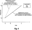
- FIG. 4 a graph internal pressure versus time shown for immersion cooled electronics arrangement 100 (shown in solid line) in comparison to the immersion cooled electronics arrangement without variable-volume chamber 112 (shown in dashed line).
- Times A, time B, and time C are indicated on the x-axis; an initial pressure P 1 and a relief pressure P 2 are shown on the y-axis, P 2 representing a pressure where a vent valve opens to fluidly couple the interior of sealed housing 102 (shown in Fig. 1 ) to the external environment.
- the immersion cooled electronics arrangement without the variable-volume chamber exhibits a relatively steep pressure increase between time A and time B, reaching relief pressure P 2 at time B. Between time B and time C internal pressure remains constant, and continued heat input to the coolant causes vapor phase coolant to issue to the external environment.
- the immersion cooled electronics arrangement having the variable-volume chamber experiences a more gradual internal pressure rise between time A and time C.
- the more gradual internal pressure increase is attributable to the decrease in the volume occupied by variable volume chamber 128 (shown in Figs 1-3 ) between times A and C (shown in Figs. 1-3 ), allowing immersion cooled electronics arrangement 100 to take longer to reach predetermined pressure P 2 .
- the relatively gradual internal pressure provided by the reduction in volume of variable-volume chamber 128 (shown in Figs. 1-3 ) allows for operation of the exemplary cooling arrangement without the need for service under conditions that would necessitate service of cooling arrangements not having a variable-chamber as described above.
- condenser 124 is shown with a segmented condenser body having segments with fins of differentiated heights.
- condenser 124 has a first fin 124A with a first height D 1 and a second fin 124B with a second height D 2 .
- First height D 1 and second height D 2 each extend into sealed housing 102 to coolant 104 and downwards (relatively to gravity), second height D 2 being greater than D 1 .
- the differing fin heights can cooperate with coolant liquid level changes within the sealed housing to change the rate of heat transfer from sealed housing 102 due to the change in the ratio of liquid and vapor phase coolant within sealed housing 102, as indicated by the lowering of the liquid level within sealed housing 102 at time C (shown in Fig. 3 ) and time B (shown in Fig. 2 ) relative to time A (shown in Fig. 1 ).
- the height differential cooperates with liquid level change within sealed housing 102 such that different portions of condenser 124 are bathed by coolant 104 according to liquid level within sealed housing 102, thereby providing a stepped change in heat transfer between condenser 124 and coolant 104.
- This allows for selecting different heat rejection paths according the temperature of dielectric coolant 104 via change in the liquid level 122. For example, at time A (shown in Fig. 1 ), pressure within the interior of sealed housing 102 is such that three heat rejection conduction paths extend through condenser 124. At time B (shown in Fig.
- pressure within the interior of sealed housing 102 is such that only a single heat rejection conduction path extends through condenser 124.
- pressure within the interior of sealed housing 102 is such that no heat rejection conduction path extends through condenser 124.
- Method 200 includes heating a coolant, e.g., coolant 104 (shown in Fig. 1 ), contained within the interior of a sealed housing, e.g., sealed housing 102 (shown in Fig. 1 ), using an electronic device, e.g., PCB arrangement 106 (shown in Fig. 1 ), as shown with box 210.
- Method 200 also includes changing the liquid level, e.g., liquid level 122 (shown in Fig. 1 ) of the dielectric coolant within the interior of sealed housing, as shown with box 220.
- Changing the liquid level can include lowering (relative to gravity) the liquid level by vaporizing with heat from the electronic component dielectric coolant disposed within the interior sealed housing.
- Changing the liquid level can include increasing the liquid level by condensing dielectric coolant disposed within the sealed housing in vapor form.
- Method 200 further includes reducing the volume of the variable-volume chamber, e.g., variable-volume chamber 112, disposed within the sealed housing, in response to pressure increase associated with the heating of the dielectric coolant, as shown with box 230.
- Method 200 can additionally include maintaining pressure within predetermined pressure range within the interior of the sealed housing while heating the coolant, changing the liquid level, and changing the volume of the variable-volume chamber, as shown with box 240.
- the predetermined pressure range can be smaller than the pressure range over a period of time that would otherwise be associated with the temperature change for the sealed housing.
Landscapes
- Engineering & Computer Science (AREA)
- Microelectronics & Electronic Packaging (AREA)
- Physics & Mathematics (AREA)
- Thermal Sciences (AREA)
- Cooling Or The Like Of Electrical Apparatus (AREA)
Abstract
Description
- The present disclosure relates to electrical systems, and more particularly to heat removal from electronics in electrical systems.
- Throughout the aerospace industry the electrical power requirements of modem aircraft are steadily increasing. These increased power requirements, in conjunction with the harsh operating environments aircraft typically experience, create a demand for higher power density electronic devices. Electrical power applied to higher power density electronics can be accompanied by relatively high rates of heat generation from resistive heating of electrical components, which must be managed within the device and removed from such devices in order to ensure reliable operation of such devices.
- Several cooling techniques may be employed by such electrical systems to remove heat from electrical devices. Examples of cooling arrangements include conduction cooling, natural convection cooling, radiation cooling, forced-air cooling, and liquid cooling. Increasing power density has led to interest in immersion cooling in certain applications, where a liquid is typically placed in direct contact with an electronic device. Immersion cooling typically requires that the container housing a liquid coolant have sufficient mechanical robustness to withstand stress associated with pressure change of the liquid within the container from heating.
- Such conventional methods and systems have generally been considered satisfactory for their intended purpose. However, there is still a need in the art for improved immersion cooling systems. The present disclosure provides a solution for this need.
- An immersion cooled electronics arrangement includes a sealed housing, a coolant contained within the sealed housing, and an electronic device disposed within the sealed housing. The sealed housing has a variable-volume alterable between at least a first volume and a second volume in response to changes in pressure within the sealed housing to reduce the rate of pressure change in the sealed housing over time from heating of the coolant.
- In certain embodiments, the coolant can include a dielectric coolant. The electronic device can be at least partially submerged within the coolant. The electronic device can include one or more of a capacitor, an inductor, a printed circuit board, a solid-state switch device, and a heat sink. The electronic device can be a solid-state power converter or a motor controller for a vehicle electrical system. The sealed housing can have a variable internal volume. The sealed housing can have a fixed internal volume. A variable-volume chamber can be disposed within the housing. The variable-volume chamber can be submerged within the coolant. An interior of the variable-volume chamber can be fluidly isolated from the coolant.
- In accordance with certain embodiments, a gas can be sealed within the variable-volume chamber. The variable-volume chamber can be evacuated. The variable-volume chamber can be in fluid communication with the environment external to the sealed housing. The variable-volume chamber can be defined within a bellows. The bellows can include an elastic body that defines the variable-volume chamber. The bellows can be metallic and can include aluminum, steel, and/or alloys thereof. It is contemplated that the bellows can have a spring constant, and the spring constant can be sized to control the volume of the variable-volume chamber of the bellows within a predetermined pressure range.
- It is also contemplated that, in accordance with certain embodiments, an ullage space can be defined within the sealed housing. The ullage space can be occupied by coolant in a vapor phase. A condenser can be disposed within the ullage space for condensing the vapor phase coolant into liquid phase coolant. A heat exchanger can be coupled to the sealed housing on a side of the housing opposite the condenser. The heat exchanger can be in thermal communication with the electronic device through the coolant. The variable-volume chamber can be disposed within the ullage space.
- A vehicular electrical system includes an immersion cooled electronics arrangement as described above. A bellows is submerged within the coolant and defines within its interior a variable-volume chamber. The variable-volume chamber is fluidly isolated from the coolant and is deformable such that the variable-volume chamber displaces a first volume of coolant and a second volume of coolant according to the temperature of the coolant.
- A method of controlling pressure within an immersion cooled electronics arrangement includes heating coolant contained within a sealed housing using an electronic device disposed within the housing, increasing pressure within the sealed housing with the heated coolant, and decreasing volume of a variable-volume chamber disposed within the housing using the increased pressure within the sealed housing.
- These and other features of the systems and methods of the subject disclosure will become more readily apparent to those skilled in the art from the following detailed description of the preferred embodiments taken in conjunction with the drawings.
- So that those skilled in the art to which the subject disclosure appertains will readily understand how to make and use the devices and methods of the subject disclosure without undue experimentation, embodiments thereof will be described in detail herein below with reference to certain figures, wherein:
-
Fig. 1 is a schematic view of an exemplary embodiment of an immersion cooled electronics arrangement constructed in accordance with the present disclosure, showing a variable-volume chamber submerged within coolant contained within a sealed housing; -
Fig. 2 is a schematic view of the immersion cooled electronics arrangement ofFig. 1 , showing the variable-volume chamber decreasing in volume in response to pressure increase within the sealed housing from heating of the coolant; -
Fig. 3 is a schematic view of the immersion cooled electronics arrangement ofFig. 1 , showing the variable-volume chamber decreasing further in volume in response to further pressure increase within the sealed housing from further heating of the coolant; -
Fig. 4 is a graph of pressure change over time for the immersion cooled electronics arrangement ofFig. 1 in comparison to the immersion cooled electronics arrangement without the variable-volume chamber, showing the rate of pressure increase in the immersion cooled electronics arrangement ofFig. 1 being slower than the immersion cooled electronics arrangement not having a variable-volume chamber; and -
Fig. 5 is a diagram of a method of controlling pressure change within an immersion cooled electronics arrangement, showing steps of the method. - Reference will now be made to the drawings wherein like reference numerals identify similar structural features or aspects of the subject disclosure. For purposes of explanation and illustration, and not limitation, a partial view of an exemplary embodiment of an immersion cooled electronics arrangement in accordance with the disclosure is shown in
Fig. 1 and is designated generally byreference character 100. Other embodiments of immersion cooled electronics arrangements and methods of removing heat from such arrangements in accordance with the disclosure, or aspects thereof, are provided inFigs. 2-5 , as will be described. The systems and methods described herein can be used in vehicular electrical systems, such as in motor controllers and/or power converters for aircraft electrical systems, though the present disclosure is not limited power converters, motor controllers, or to aircraft electrical systems in general. - Referring to
Fig. 1 , immersion cooledelectronics arrangement 100 is shown. Immersion cooledelectronics arrangement 100 includes a sealedhousing 102 and acoolant 104 contained within sealedhousing 102. One or more electronic devices, e.g., a printed circuit board (PCB)arrangement 106, aninductor 108, and acapacitor 110, are disposed within sealedhousing 102 and submerged withincoolant 104. A variable-volume chamber 112 is also disposed in sealedhousing 102 and submerged withincoolant 104, variable-volume chamber 112 being adapted and configured to displace a differential volume of coolant according to the temperature ofcoolant 104 to limit the pressure change within sealedhousing 102 than would otherwise be associated with the temperature change. - Coolant 104 is electrically insulative, thermally conductive coolant, and may include a dielectric coolant. Examples of suitable coolants include fluorocarbons, such as perfluorohexane (FC-72), perfluoro (FC-75), and/or perfluorotripentylamine (FC-70). FC-72, FC-75, and FC-70 are available under the tradename Flourinert® from the 3M Company of Maplewood, Minnesota.
- A portion of
coolant 104 in a liquid phase is disposed within a lower (relative to the direction of gravity) portion of the interior of sealedhousing 102. A portion ofcoolant 104 in a vapor phase is disposed within anullage space 120 in an upper (relative to the direction of gravity) portion of the interior of sealedhousing 102. Asurface 122 ofliquid phase coolant 104bounds ullage space 120, separating liquid phase coolant from vapor phase coolant contained within sealedhousing 102. As will be appreciated by those of skill in the art in view of the present disclosure, the relative proportion of liquid phase coolant to vapor phase coolant is a function by the temperature ofcoolant 104 and internal pressure within sealedhousing 102. - A
condenser 124 is disposed withinullage space 120.Condenser 124 is in thermal communication with aheat exchanger 126 through a wall of sealedhousing 102,heat exchanger 126 being disposed on an exterior of sealedhousing 102opposite condenser 124.Condenser 124 andheat exchanger 126 each have a plurality of fins for purposes of providing increased surface area for heat transfer, and as illustrated include discrete finned bodies connected to sealedhousing 102. As will be appreciated by those of skilled in the art, either or both ofcondenser 124 andheat exchanger 126 may be defined by sealedhousing 102, such as by fins defined by one or more interior and/or exterior surfaces of the walls of sealedhousing 102. - In the illustrated exemplary embodiment,
PCB arrangement 106 includes a printed circuit board (PCB) 114, a solid-state switch device 116, andheat sink 118 that are disposed within sealedhousing 102 and submerged withincoolant 104. Solid-state switch device 116 is connected to a surface ofPCB arrangement 106, and may include a field effect transistor device like a MOSFET or an insulated gate bipolar transistor (IGBT) device for a power converter.Heat sink 118 is connected to solid-state switch device 116, serves to increase the rate heat transfer from solid-state switch device 116 tocoolant 104, and allows for relatively compact spacing of electrical components on the surface ofPCB 114. - In the illustrated exemplary embodiment, variable-
volume chamber 112 is defined within anelastic body 128.Elastic body 128 fluidly isolates variable-volume chamber 112 fromcoolant 104, is alterable in volume according to pressure exerted onelastic body 128 bycoolant 104, and may include ametallic material 130, such as aluminum, steel, or alloys thereof. In the illustrated exemplary embodimentelastic body 128 is a metallic bellows having a plurality of segments and alterable between a first volume (shown inFig. 1 ), a second volume (shown inFig. 2 ) that is smaller than the first volume, and a third volume (shown inFig. 3 ) that is smaller than the second volume in response to changes in pressure within the sealed chamber. Although the exemplary embodiment described herein includes variable-volume chamber 112 disposed within fixed-volume sealedhousing 102, it is to be appreciated and understood that in certain embodiments sealedhousing 102 defines variable-volume chamber 112 and is itself alterable between at least a first volume and a second volume according to pressure within the sealedhousing 102. - It is contemplated that
elastic body 128 and variable-volume chamber 112 defined therein have a coefficient of thermal expansion that is different from the coefficient of thermal expansion ofdielectric coolant 104. For example, variable-volume chamber 112 may be evacuated and sealed with respect to the interior of sealedhousing 102. Alternatively, variable-volume chamber 112 can be occupied by agas 132, the gas being sealed within variable-volume chamber 112 and fluidly isolated from the interior of sealedhousing 102. It is also contemplated that variable-volume chamber 112 can be fluidly isolated from the interior of sealedhousing 102 and in fluid communication with the environment external to sealedhousing 102, such as through a vent ordiaphragm structure 133. These arrangements allow the space occupied by variable-volume chamber 112 to change according to pressure within the interior of sealedhousing 102, which in turn is influenced by the temperature ofdielectric coolant 104. Thus, variable-volume chamber 112 reduces pressure rise within the interior of sealedhousing 102 as a function of temperature increase by decreasing in volume, thereby causing sealedhousing 102 to experience a smaller pressure gradient relative to ambient pressure for a given amount of heating, allowing sealedhousing 102 to be less massive than would otherwise be necessary. - Referring now to
Figs. 1-3 , immersion cooledelectronics arrangement 100 is shown with variable-volume chamber 112 responding to increasing pressure within the interior of sealedhousing 102. With reference toFig. 1 , variable-volume chamber 112 at a time A wheredielectric coolant 104 is relatively cool and internal pressure within sealedhousing 102 is relatively low. - With reference to
Fig. 2 , immersion cooledelectronics arrangement 100 is shown at time B. At time Bdielectric coolant 104 pressure within sealedhousing 102 is higher than at time A, such as may result fromdielectric coolant 104 having been heated during the intervening period between time A (shown inFig. 1 ) and time B. Heating may be the result, for example, of heat absorbed from resistive heating of current-carrying elements ofPCB arrangement 106,inductor 108, and/orcapacitor 110, heat indicated with bubbles associated with nucleated boiling ofdielectric coolant 104. As indicated by the decrease in volume of variable-volume chamber 112 shown inFig. 2 in comparison toFig. 1 , variable-volume chamber 112 compresses in response to the increased pressure, reducing rate of pressure increase that would result within sealedhousing 102 without variable-volume chamber 112 with heating ofdielectric coolant 104. - With reference to
Fig. 3 , immersion cooledelectronics arrangement 100 is shown at time C. At time C pressure within sealedhousing 102 is higher than at time B,dielectric coolant 104 having been further heated during the intervening period between time B (shown inFig. 2 ) and time C. Responsive to the increased pressure, variable-volume chamber 112 further decreases in volume, slowing the rate of pressure increase within the interior of sealedhousing 102 that otherwise would result from the further heating ofdielectric coolant 104. - Referring to
Fig. 4 , a graph internal pressure versus time shown for immersion cooled electronics arrangement 100 (shown in solid line) in comparison to the immersion cooled electronics arrangement without variable-volume chamber 112 (shown in dashed line). Times A, time B, and time C are indicated on the x-axis; an initial pressure P1 and a relief pressure P2 are shown on the y-axis, P2 representing a pressure where a vent valve opens to fluidly couple the interior of sealed housing 102 (shown inFig. 1 ) to the external environment. - As indicated with the dashed-line in
Fig. 4 , the immersion cooled electronics arrangement without the variable-volume chamber exhibits a relatively steep pressure increase between time A and time B, reaching relief pressure P2 at time B. Between time B and time C internal pressure remains constant, and continued heat input to the coolant causes vapor phase coolant to issue to the external environment. - As indicated with the solid-line in
Fig. 4 , the immersion cooled electronics arrangement having the variable-volume chamber experiences a more gradual internal pressure rise between time A and time C. The more gradual internal pressure increase is attributable to the decrease in the volume occupied by variable volume chamber 128 (shown inFigs 1-3 ) between times A and C (shown inFigs. 1-3 ), allowing immersion cooledelectronics arrangement 100 to take longer to reach predetermined pressure P2. In certain embodiments, the relatively gradual internal pressure provided by the reduction in volume of variable-volume chamber 128 (shown inFigs. 1-3 ) allows for operation of the exemplary cooling arrangement without the need for service under conditions that would necessitate service of cooling arrangements not having a variable-chamber as described above. - Referring again to
Figs. 1-3 ,condenser 124 is shown with a segmented condenser body having segments with fins of differentiated heights. In the illustratedexemplary embodiment condenser 124 has afirst fin 124A with a first height D1 and asecond fin 124B with a second height D2. First height D1 and second height D2 each extend into sealedhousing 102 tocoolant 104 and downwards (relatively to gravity), second height D2 being greater than D1. The differing fin heights can cooperate with coolant liquid level changes within the sealed housing to change the rate of heat transfer from sealedhousing 102 due to the change in the ratio of liquid and vapor phase coolant within sealedhousing 102, as indicated by the lowering of the liquid level within sealedhousing 102 at time C (shown inFig. 3 ) and time B (shown inFig. 2 ) relative to time A (shown inFig. 1 ). - As will be appreciated by those of skill in the art in view of the present disclosure, the height differential cooperates with liquid level change within sealed
housing 102 such that different portions ofcondenser 124 are bathed bycoolant 104 according to liquid level within sealedhousing 102, thereby providing a stepped change in heat transfer betweencondenser 124 andcoolant 104. This allows for selecting different heat rejection paths according the temperature ofdielectric coolant 104 via change in theliquid level 122. For example, at time A (shown inFig. 1 ), pressure within the interior of sealedhousing 102 is such that three heat rejection conduction paths extend throughcondenser 124. At time B (shown inFig. 2 ), pressure within the interior of sealedhousing 102 is such that only a single heat rejection conduction path extends throughcondenser 124. At time C (shown inFig. 3 ), pressure within the interior of sealedhousing 102 is such that no heat rejection conduction path extends throughcondenser 124. - With reference to
Fig. 5 , amethod 200 of controlling pressure rise in an immersion cooled electronics arrangement is shown.Method 200 includes heating a coolant, e.g., coolant 104 (shown inFig. 1 ), contained within the interior of a sealed housing, e.g., sealed housing 102 (shown inFig. 1 ), using an electronic device, e.g., PCB arrangement 106 (shown inFig. 1 ), as shown withbox 210.Method 200 also includes changing the liquid level, e.g., liquid level 122 (shown inFig. 1 ) of the dielectric coolant within the interior of sealed housing, as shown withbox 220. Changing the liquid level can include lowering (relative to gravity) the liquid level by vaporizing with heat from the electronic component dielectric coolant disposed within the interior sealed housing. Changing the liquid level can include increasing the liquid level by condensing dielectric coolant disposed within the sealed housing in vapor form. -
Method 200 further includes reducing the volume of the variable-volume chamber, e.g., variable-volume chamber 112, disposed within the sealed housing, in response to pressure increase associated with the heating of the dielectric coolant, as shown withbox 230.Method 200 can additionally include maintaining pressure within predetermined pressure range within the interior of the sealed housing while heating the coolant, changing the liquid level, and changing the volume of the variable-volume chamber, as shown withbox 240. The predetermined pressure range can be smaller than the pressure range over a period of time that would otherwise be associated with the temperature change for the sealed housing. - The methods and systems of the present disclosure, as described above and shown in the drawings, provide for immersion cooled electronic devices with superior properties including improved pressure control. While the apparatus and methods of the subject disclosure have been shown and described with reference to preferred embodiments, those skilled in the art will readily appreciate that changes and/or modifications may be made thereto without departing from the scope of the subject disclosure.
Claims (15)
- An immersion cooled electronics arrangement (100), comprising:a sealed housing (102);a coolant (104) contained within the sealed housing (102); andan electronic device disposed within the sealed housing (102) and in thermal communication with the coolant (104), a volume of the sealed housing (102) being alterable between at least a first volume and a second volume in response to changes in pressure within the sealed housing (102) to reduce the rate of pressure change over time in the sealed housing (102) from heating of the coolant (104).
- An immersion cooled electronics arrangement (100) as recited in claim 1, wherein the sealed housing (102) has a fixed internal volume.
- An immersion cooled electronics arrangement (100) as recited in claim 1 or 2, further including a variable-volume chamber (112) disposed within the sealed housing (102) fluidly isolated from the coolant (104).
- An immersion cooled electronics arrangement (100) as recited in claim 3, further including a gas (132) sealed within the variable-volume chamber (112).
- An immersion cooled electronics arrangement (100) as recited in claim 3 or 4, wherein the variable-volume chamber (112) encloses an evacuated space sealed from an interior of the sealed housing (102), or wherein the variable-volume chamber (112) is in fluid communication with environment external to the sealed housing (102), or wherein the variable-volume chamber (112) is submerged within the coolant (104).
- An immersion cooled electronics arrangement (100) as recited in any preceding claim, further including a bellows defining a variable-volume chamber (112) disposed within the sealed housing (102), wherein preferably the bellows includes a metallic material.
- An immersion cooled electronics arrangement (100) as recited in any preceding claim, wherein the sealed housing (102) and the coolant (104) define therebetween an ullage space (120), the immersion cooled electronics arrangement (100) preferably further including a condenser (124) disposed within the ullage space (120), or a heat exchanger (126) coupled to the housing (102) opposite the ullage space (120).
- An immersion cooled electronics arrangement (100) as recited in claim 7, wherein the condenser (124) includes a first fin (124A) and a second fin (124B) having lengths extending towards the coolant (104), the second fin (124B) having length (D2) that is greater than the length (D1) of the first fin (124A).
- An immersion cooled electronics arrangement (100) as recited in any preceding claim, wherein the electronic devices comprises at least one of a capacitor (110), an inductor (108), a printed circuit board (106), a solid-state switch device (116), heat sink (118), a solid-state power converter, and a motor controller.
- An immersion cooled electronics arrangement (100) as recited in any preceding claim, wherein the coolant (104) includes a dielectric coolant.
- An immersion cooled electronics arrangement (100) as recited in any preceding claim, wherein the electronic device is at least partially submerged within the coolant (104).
- An aircraft electrical system electronics cooling arrangement (100), comprising:a sealed housing (102);a coolant (104) contained within the sealed housing (102);an electronic device disposed within the housing (102) and at least partially submerged within the coolant (104); anda bellows defining a variable-volume chamber (112) submerged within the coolant (104), the variable-volume chamber (112) being alterable between at least a first volume and a second volume in response to changes in pressure within the sealed housing (102) to reduce change in pressure within the sealed housing (102),wherein the variable-volume chamber (112) is fluidly isolated from the interior of the sealed housing (102).
- A cooling arrangement (100) as recited in claim 12, wherein the variable-volume chamber (112) is in fluid communication with the environment external to the sealed housing (102).
- A method of controlling pressure within a sealed housing (102) of an immersion cooled electronics arrangement (100), comprising:heating coolant (104) contained within a sealed housing (102) using an electronic device disposed within the housing (102);increasing pressure within the sealed housing (102); anddecreasing volume of a variable-volume chamber (112) disposed within the housing (102) using the increased pressure within the sealed housing (102).
- A method as recited in claim 14, further comprising lowering a liquid level within the sealed housing (102) in response to the increased pressure within the housing (102).
Applications Claiming Priority (1)
| Application Number | Priority Date | Filing Date | Title |
|---|---|---|---|
| US15/093,637 US10070558B2 (en) | 2016-04-07 | 2016-04-07 | Immersion cooled electronic assemblies |
Publications (3)
| Publication Number | Publication Date |
|---|---|
| EP3229571A2 true EP3229571A2 (en) | 2017-10-11 |
| EP3229571A3 EP3229571A3 (en) | 2017-10-18 |
| EP3229571B1 EP3229571B1 (en) | 2025-11-12 |
Family
ID=58448342
Family Applications (1)
| Application Number | Title | Priority Date | Filing Date |
|---|---|---|---|
| EP17162294.7A Active EP3229571B1 (en) | 2016-04-07 | 2017-03-22 | Immersion cooled electronic assemblies |
Country Status (2)
| Country | Link |
|---|---|
| US (1) | US10070558B2 (en) |
| EP (1) | EP3229571B1 (en) |
Cited By (5)
| Publication number | Priority date | Publication date | Assignee | Title |
|---|---|---|---|---|
| WO2020200523A1 (en) * | 2019-04-02 | 2020-10-08 | Eaton Intelligent Power Limited | Immersion cooling systems for electrical power components |
| CN115460833A (en) * | 2022-09-29 | 2022-12-09 | 西安易朴通讯技术有限公司 | Two-phase immersion liquid cooling apparatus and system |
| WO2025218979A1 (en) * | 2024-04-18 | 2025-10-23 | Wieland-Werke Ag | Modular functional unit for connecting high-performance electronic components |
| US12641706B1 (en) | 2025-04-18 | 2026-05-26 | LiquaCool IP LLC | Thermal riser system |
| US12652780B2 (en) | 2024-10-06 | 2026-06-09 | LiquaCool IP LLC | Enclosed liquid cooling system |
Families Citing this family (39)
| Publication number | Priority date | Publication date | Assignee | Title |
|---|---|---|---|---|
| WO2017047151A1 (en) * | 2015-09-14 | 2017-03-23 | 三菱電機株式会社 | Cooler, power conversion device and cooling system |
| EP3379375A4 (en) * | 2015-11-16 | 2018-12-26 | Exascaler Inc. | Electronic device for liquid immersion cooling and cooling system using same |
| US10930575B2 (en) * | 2016-09-30 | 2021-02-23 | Intel Corporation | Reconfigurable cooling assembly for integrated circuitry |
| CN109782880B (en) * | 2017-11-15 | 2022-05-31 | 英业达科技有限公司 | Immersion cooling apparatus and server system thereof |
| US10568236B2 (en) | 2017-12-27 | 2020-02-18 | International Business Machines Corporation | Space-efficient pressure relief mechanism for immersion cooling of computing elements |
| US10622283B2 (en) * | 2018-06-14 | 2020-04-14 | International Business Machines Corporation | Self-contained liquid cooled semiconductor packaging |
| US11102912B2 (en) | 2018-09-19 | 2021-08-24 | TMGCore, LLC | Liquid immersion cooling platform |
| US10694643B2 (en) | 2018-09-19 | 2020-06-23 | TMGCore, LLC | Ballast blocks for a liquid immersion cooling system |
| US10624237B2 (en) | 2018-09-19 | 2020-04-14 | TMGCore, LLC | Liquid immersion cooling vessel and components thereof |
| US11129298B2 (en) | 2018-09-19 | 2021-09-21 | Tmgcore, Inc. | Process for liquid immersion cooling |
| US11895804B2 (en) | 2018-09-19 | 2024-02-06 | Tmgcore, Inc. | Fluid breakdown detection systems and processes useful for liquid immersion cooling |
| US10617032B1 (en) | 2018-09-19 | 2020-04-07 | TMGCore, LLC | Robot for a liquid immersion cooling system |
| US10969842B2 (en) | 2018-09-19 | 2021-04-06 | TMGCore, LLC | Chassis for a liquid immersion cooling system |
| US10653043B2 (en) | 2018-09-19 | 2020-05-12 | TMGCore, LLC | Vapor management system for a liquid immersion cooling system |
| US12408308B2 (en) | 2018-11-16 | 2025-09-02 | Modine LLC | Hydrofire rods for liquid immersion cooling platform |
| US11785747B2 (en) | 2018-11-16 | 2023-10-10 | TMGCore. INC. | Methods and devices for testing immersion cooling controllers |
| JP7332851B2 (en) * | 2018-12-28 | 2023-08-24 | 富士通株式会社 | cooling system |
| EP3928603A4 (en) * | 2019-02-18 | 2022-12-07 | 3M Innovative Properties Company | Pressure control for thermal management system |
| JP7244747B2 (en) * | 2019-02-28 | 2023-03-23 | 富士通株式会社 | Liquid immersion tank and liquid immersion cooling device |
| TWI714037B (en) * | 2019-03-26 | 2020-12-21 | 緯創資通股份有限公司 | Air flow generating system for liquid tank, immersion cooling apparatus having the same, and method for operating the same |
| US10765033B1 (en) * | 2019-05-23 | 2020-09-01 | Microsoft Technology Licensing, Llc | Immersion cooling enclosures with insulating liners |
| TWM589293U (en) * | 2019-08-23 | 2020-01-11 | 緯創資通股份有限公司 | Heat dissipation module and electronic device |
| US10820447B1 (en) * | 2019-09-30 | 2020-10-27 | Baidu Usa Llc | Immersion cooling system with top mounted bus bar |
| US11163013B2 (en) * | 2019-10-30 | 2021-11-02 | Hamilton Sundstrand Corporation | Electrical device partial discharge monitoring |
| CN112902548B (en) * | 2019-11-19 | 2022-11-04 | 英业达科技有限公司 | cooling device |
| EP3958660B1 (en) * | 2020-08-21 | 2024-09-18 | OneSubsea IP UK Limited | Subsea electronic shock-absorbing assembly |
| US12035508B2 (en) | 2020-12-29 | 2024-07-09 | Modine LLC | Liquid immersion cooling platform and components thereof |
| JP7574701B2 (en) * | 2021-03-10 | 2024-10-29 | 株式会社デンソー | Cooling system |
| JP2022138222A (en) * | 2021-03-10 | 2022-09-26 | 株式会社デンソー | Cooling device |
| JP7494138B2 (en) * | 2021-03-24 | 2024-06-03 | 日立Astemo株式会社 | Electronic Control Unit |
| TWI799854B (en) * | 2021-05-07 | 2023-04-21 | 緯穎科技服務股份有限公司 | Immersion cooling system, electronic apparatus having the same and pressure adjusting module |
| TW202328569A (en) | 2021-10-11 | 2023-07-16 | 美商Tmg科爾股份有限公司 | Methods and devices to employ air cooled computers in liquid immersion cooling |
| US12049239B2 (en) | 2021-11-12 | 2024-07-30 | Modine LLC | Distributed computing network comprised of autonomous vehicles carrying liquid immersion cooling platforms |
| CN116666804A (en) * | 2022-02-18 | 2023-08-29 | 通用汽车环球科技运作有限责任公司 | Control system for two-phase immersion cooling of electric vehicle components |
| US12464689B2 (en) | 2022-05-26 | 2025-11-04 | General Electric Company | Thermal management system for a power converter |
| WO2024237947A1 (en) | 2023-05-16 | 2024-11-21 | MTS IP Holdings Ltd | Bellows for immersion cooling |
| TWI898371B (en) * | 2023-12-27 | 2025-09-21 | 致茂電子股份有限公司 | Electronic equipment using immersion liquid cooling style and its electronic module |
| JP2025119679A (en) * | 2024-02-02 | 2025-08-15 | ミネベアパワーデバイス株式会社 | Semiconductor Devices |
| CN121586223B (en) * | 2025-11-28 | 2026-08-11 | 吉林冰河制冷技术有限公司 | Modularized immersed cooling device with isolation and recovery functions |
Citations (2)
| Publication number | Priority date | Publication date | Assignee | Title |
|---|---|---|---|---|
| CN103414219A (en) * | 2013-07-16 | 2013-11-27 | 陈夏新 | Electric vehicle charger |
| WO2016146698A1 (en) * | 2015-03-16 | 2016-09-22 | Nerdalize B.V. | Module for cooling a heat generating component |
Family Cites Families (19)
| Publication number | Priority date | Publication date | Assignee | Title |
|---|---|---|---|---|
| JPS61220359A (en) | 1985-03-26 | 1986-09-30 | Hitachi Ltd | Cooling structure of semiconductor module |
| US4847731A (en) | 1988-07-05 | 1989-07-11 | The United States Of America As Represented By The Secretary Of The Navy | Liquid cooled high density packaging for high speed circuits |
| US5206791A (en) | 1992-02-07 | 1993-04-27 | Digital Equipment Corporation | Bellows heat pipe apparatus for cooling systems |
| US5373417A (en) * | 1994-02-28 | 1994-12-13 | Motorola, Inc. | Liquid-cooled circuit package with micro-bellows for controlling expansion |
| JPH09310661A (en) * | 1996-05-20 | 1997-12-02 | Denso Corp | Fuel supply device for direct injection gasoline engine |
| DE10152260A1 (en) | 2001-10-20 | 2003-04-30 | Isad Electronic Sys Gmbh & Co | Boiling bath cooler for electronic appliance, such as power electronic module |
| AUPS255902A0 (en) * | 2002-05-24 | 2002-06-13 | Ultimate Medical Pty. Ltd. | Device and method for pressure indication |
| US7165413B2 (en) | 2004-07-09 | 2007-01-23 | Symons Robert S | Integrated liquid cooling device with immersed electronic components |
| US7458413B2 (en) | 2004-11-12 | 2008-12-02 | International Business Machines Corporation | Semiconductor chip heat transfer device |
| US7656025B2 (en) | 2006-11-21 | 2010-02-02 | The Boeing Company | Direct semiconductor contact ebullient cooling package |
| US20080302115A1 (en) | 2007-06-08 | 2008-12-11 | Coda Octopus Group, Inc. | Combined pressure compensator and cooling unit |
| US8014150B2 (en) | 2009-06-25 | 2011-09-06 | International Business Machines Corporation | Cooled electronic module with pump-enhanced, dielectric fluid immersion-cooling |
| US8369091B2 (en) * | 2010-06-29 | 2013-02-05 | International Business Machines Corporation | Interleaved, immersion-cooling apparatus and method for an electronic subsystem of an electronics rack |
| US8619425B2 (en) * | 2011-10-26 | 2013-12-31 | International Business Machines Corporation | Multi-fluid, two-phase immersion-cooling of electronic component(s) |
| US8953317B2 (en) * | 2011-10-26 | 2015-02-10 | International Business Machines Corporation | Wicking vapor-condenser facilitating immersion-cooling of electronic component(s) |
| US9144179B2 (en) * | 2013-02-01 | 2015-09-22 | Dell Products, L.P. | System and method for powering multiple electronic devices operating within an immersion cooling vessel |
| US9464854B2 (en) | 2013-02-01 | 2016-10-11 | Dell Products, Lp | Techniques for controlling vapor pressure in an immersion cooling tank |
| US9049800B2 (en) | 2013-02-01 | 2015-06-02 | Dell Products L.P. | Immersion server, immersion server drawer, and rack-mountable immersion server drawer-based cabinet |
| US9949022B2 (en) * | 2014-09-29 | 2018-04-17 | Keith Kropf | Underwater communication systems, underwater speakers, underwater microphone assemblies and methods |
-
2016
- 2016-04-07 US US15/093,637 patent/US10070558B2/en active Active
-
2017
- 2017-03-22 EP EP17162294.7A patent/EP3229571B1/en active Active
Patent Citations (2)
| Publication number | Priority date | Publication date | Assignee | Title |
|---|---|---|---|---|
| CN103414219A (en) * | 2013-07-16 | 2013-11-27 | 陈夏新 | Electric vehicle charger |
| WO2016146698A1 (en) * | 2015-03-16 | 2016-09-22 | Nerdalize B.V. | Module for cooling a heat generating component |
Cited By (5)
| Publication number | Priority date | Publication date | Assignee | Title |
|---|---|---|---|---|
| WO2020200523A1 (en) * | 2019-04-02 | 2020-10-08 | Eaton Intelligent Power Limited | Immersion cooling systems for electrical power components |
| CN115460833A (en) * | 2022-09-29 | 2022-12-09 | 西安易朴通讯技术有限公司 | Two-phase immersion liquid cooling apparatus and system |
| WO2025218979A1 (en) * | 2024-04-18 | 2025-10-23 | Wieland-Werke Ag | Modular functional unit for connecting high-performance electronic components |
| US12652780B2 (en) | 2024-10-06 | 2026-06-09 | LiquaCool IP LLC | Enclosed liquid cooling system |
| US12641706B1 (en) | 2025-04-18 | 2026-05-26 | LiquaCool IP LLC | Thermal riser system |
Also Published As
| Publication number | Publication date |
|---|---|
| EP3229571A3 (en) | 2017-10-18 |
| EP3229571B1 (en) | 2025-11-12 |
| US20170295670A1 (en) | 2017-10-12 |
| US10070558B2 (en) | 2018-09-04 |
Similar Documents
| Publication | Publication Date | Title |
|---|---|---|
| EP3229571B1 (en) | Immersion cooled electronic assemblies | |
| US10405459B2 (en) | Actuated immersion cooled electronic assemblies | |
| EP3229572B1 (en) | Immersion cooling systems and methods | |
| US10779436B2 (en) | Space-efficient pressure relief mechanism for immersion cooling of computing elements | |
| EP3229573B1 (en) | Immersion cooling systems and methods | |
| EP3232753B1 (en) | Immersion cooling arrangements for electronic devices | |
| US12050061B2 (en) | Shrouded powder patch | |
| EP3336862B1 (en) | Integrated inductor windings and heat pipes | |
| US3270250A (en) | Liquid vapor cooling of electrical components | |
| US20200386479A1 (en) | Cooling system | |
| US11644249B2 (en) | Electronic apparatus | |
| US10962300B2 (en) | Cooling device with a pressure adjuster | |
| JP2023508398A (en) | cooling module | |
| US7902957B2 (en) | Phase change cooled electrical resistor | |
| JP2019204899A (en) | Vapor cooling device | |
| CN108990369B (en) | Power electronic system and manufacturing method thereof | |
| WO2025160390A1 (en) | Method to transfer heat from small form factor pluggable connector to remote heat sink | |
| WO2018179571A1 (en) | Immersion boiling cooling method, immersion boiling cooling device, and electronic apparatus | |
| TWI709724B (en) | Cooling system | |
| EP4380321A1 (en) | Circuit board with built-in components and method of manufacturing circuit board with built-in components | |
| JP2026058619A (en) | Electronic circuit board enclosure | |
| TR2025003234Y (en) | CONDUCTIVE REFRIGERATED CASE WITH POOL-BOILED COLD PLATE. | |
| WO2020021454A1 (en) | Heat removal from electronics in downhole tools |
Legal Events
| Date | Code | Title | Description |
|---|---|---|---|
| PUAI | Public reference made under article 153(3) epc to a published international application that has entered the european phase |
Free format text: ORIGINAL CODE: 0009012 |
|
| STAA | Information on the status of an ep patent application or granted ep patent |
Free format text: STATUS: THE APPLICATION HAS BEEN PUBLISHED |
|
| PUAL | Search report despatched |
Free format text: ORIGINAL CODE: 0009013 |
|
| AK | Designated contracting states |
Kind code of ref document: A2 Designated state(s): AL AT BE BG CH CY CZ DE DK EE ES FI FR GB GR HR HU IE IS IT LI LT LU LV MC MK MT NL NO PL PT RO RS SE SI SK SM TR |
|
| AX | Request for extension of the european patent |
Extension state: BA ME |
|
| AK | Designated contracting states |
Kind code of ref document: A3 Designated state(s): AL AT BE BG CH CY CZ DE DK EE ES FI FR GB GR HR HU IE IS IT LI LT LU LV MC MK MT NL NO PL PT RO RS SE SI SK SM TR |
|
| AX | Request for extension of the european patent |
Extension state: BA ME |
|
| RIC1 | Information provided on ipc code assigned before grant |
Ipc: H05K 7/20 20060101AFI20170908BHEP Ipc: H05K 5/06 20060101ALI20170908BHEP |
|
| STAA | Information on the status of an ep patent application or granted ep patent |
Free format text: STATUS: REQUEST FOR EXAMINATION WAS MADE |
|
| 17P | Request for examination filed |
Effective date: 20180313 |
|
| RBV | Designated contracting states (corrected) |
Designated state(s): AL AT BE BG CH CY CZ DE DK EE ES FI FR GB GR HR HU IE IS IT LI LT LU LV MC MK MT NL NO PL PT RO RS SE SI SK SM TR |
|
| STAA | Information on the status of an ep patent application or granted ep patent |
Free format text: STATUS: EXAMINATION IS IN PROGRESS |
|
| 17Q | First examination report despatched |
Effective date: 20201001 |
|
| GRAP | Despatch of communication of intention to grant a patent |
Free format text: ORIGINAL CODE: EPIDOSNIGR1 |
|
| STAA | Information on the status of an ep patent application or granted ep patent |
Free format text: STATUS: GRANT OF PATENT IS INTENDED |
|
| INTG | Intention to grant announced |
Effective date: 20250122 |
|
| GRAJ | Information related to disapproval of communication of intention to grant by the applicant or resumption of examination proceedings by the epo deleted |
Free format text: ORIGINAL CODE: EPIDOSDIGR1 |
|
| STAA | Information on the status of an ep patent application or granted ep patent |
Free format text: STATUS: EXAMINATION IS IN PROGRESS |
|
| INTC | Intention to grant announced (deleted) | ||
| GRAP | Despatch of communication of intention to grant a patent |
Free format text: ORIGINAL CODE: EPIDOSNIGR1 |
|
| STAA | Information on the status of an ep patent application or granted ep patent |
Free format text: STATUS: GRANT OF PATENT IS INTENDED |
|
| INTG | Intention to grant announced |
Effective date: 20250708 |
|
| GRAS | Grant fee paid |
Free format text: ORIGINAL CODE: EPIDOSNIGR3 |
|
| GRAA | (expected) grant |
Free format text: ORIGINAL CODE: 0009210 |
|
| STAA | Information on the status of an ep patent application or granted ep patent |
Free format text: STATUS: THE PATENT HAS BEEN GRANTED |
|
| AK | Designated contracting states |
Kind code of ref document: B1 Designated state(s): AL AT BE BG CH CY CZ DE DK EE ES FI FR GB GR HR HU IE IS IT LI LT LU LV MC MK MT NL NO PL PT RO RS SE SI SK SM TR |
|
| REG | Reference to a national code |
Ref country code: CH Ref legal event code: F10 Free format text: ST27 STATUS EVENT CODE: U-0-0-F10-F00 (AS PROVIDED BY THE NATIONAL OFFICE) Effective date: 20251112 Ref country code: GB Ref legal event code: FG4D |
|
| REG | Reference to a national code |
Ref country code: DE Ref legal event code: R096 Ref document number: 602017092633 Country of ref document: DE |
|
| REG | Reference to a national code |
Ref country code: IE Ref legal event code: FG4D |
|
| REG | Reference to a national code |
Ref country code: NL Ref legal event code: MP Effective date: 20251112 |
|
| PG25 | Lapsed in a contracting state [announced via postgrant information from national office to epo] |
Ref country code: ES Free format text: LAPSE BECAUSE OF FAILURE TO SUBMIT A TRANSLATION OF THE DESCRIPTION OR TO PAY THE FEE WITHIN THE PRESCRIBED TIME-LIMIT Effective date: 20251112 |
|
| REG | Reference to a national code |
Ref country code: LT Ref legal event code: MG9D |
|
| PG25 | Lapsed in a contracting state [announced via postgrant information from national office to epo] |
Ref country code: NO Free format text: LAPSE BECAUSE OF FAILURE TO SUBMIT A TRANSLATION OF THE DESCRIPTION OR TO PAY THE FEE WITHIN THE PRESCRIBED TIME-LIMIT Effective date: 20260212 |
|
| PG25 | Lapsed in a contracting state [announced via postgrant information from national office to epo] |
Ref country code: AT Free format text: LAPSE BECAUSE OF FAILURE TO SUBMIT A TRANSLATION OF THE DESCRIPTION OR TO PAY THE FEE WITHIN THE PRESCRIBED TIME-LIMIT Effective date: 20251112 Ref country code: FI Free format text: LAPSE BECAUSE OF FAILURE TO SUBMIT A TRANSLATION OF THE DESCRIPTION OR TO PAY THE FEE WITHIN THE PRESCRIBED TIME-LIMIT Effective date: 20251112 Ref country code: HR Free format text: LAPSE BECAUSE OF FAILURE TO SUBMIT A TRANSLATION OF THE DESCRIPTION OR TO PAY THE FEE WITHIN THE PRESCRIBED TIME-LIMIT Effective date: 20251112 |
|
| REG | Reference to a national code |
Ref country code: AT Ref legal event code: MK05 Ref document number: 1857940 Country of ref document: AT Kind code of ref document: T Effective date: 20251112 |
|
| PG25 | Lapsed in a contracting state [announced via postgrant information from national office to epo] |
Ref country code: NL Free format text: LAPSE BECAUSE OF FAILURE TO SUBMIT A TRANSLATION OF THE DESCRIPTION OR TO PAY THE FEE WITHIN THE PRESCRIBED TIME-LIMIT Effective date: 20251112 |
|
| PG25 | Lapsed in a contracting state [announced via postgrant information from national office to epo] |
Ref country code: RS Free format text: LAPSE BECAUSE OF FAILURE TO SUBMIT A TRANSLATION OF THE DESCRIPTION OR TO PAY THE FEE WITHIN THE PRESCRIBED TIME-LIMIT Effective date: 20260212 |
|
| PG25 | Lapsed in a contracting state [announced via postgrant information from national office to epo] |
Ref country code: IS Free format text: LAPSE BECAUSE OF FAILURE TO SUBMIT A TRANSLATION OF THE DESCRIPTION OR TO PAY THE FEE WITHIN THE PRESCRIBED TIME-LIMIT Effective date: 20260312 |
|
| PGFP | Annual fee paid to national office [announced via postgrant information from national office to epo] |
Ref country code: FR Payment date: 20260220 Year of fee payment: 10 |
|
| PG25 | Lapsed in a contracting state [announced via postgrant information from national office to epo] |
Ref country code: PT Free format text: LAPSE BECAUSE OF FAILURE TO SUBMIT A TRANSLATION OF THE DESCRIPTION OR TO PAY THE FEE WITHIN THE PRESCRIBED TIME-LIMIT Effective date: 20260312 |
|
| PG25 | Lapsed in a contracting state [announced via postgrant information from national office to epo] |
Ref country code: PL Free format text: LAPSE BECAUSE OF FAILURE TO SUBMIT A TRANSLATION OF THE DESCRIPTION OR TO PAY THE FEE WITHIN THE PRESCRIBED TIME-LIMIT Effective date: 20251112 |
|
| PG25 | Lapsed in a contracting state [announced via postgrant information from national office to epo] |
Ref country code: LV Free format text: LAPSE BECAUSE OF FAILURE TO SUBMIT A TRANSLATION OF THE DESCRIPTION OR TO PAY THE FEE WITHIN THE PRESCRIBED TIME-LIMIT Effective date: 20251112 |
|
| PG25 | Lapsed in a contracting state [announced via postgrant information from national office to epo] |
Ref country code: BG Free format text: LAPSE BECAUSE OF FAILURE TO SUBMIT A TRANSLATION OF THE DESCRIPTION OR TO PAY THE FEE WITHIN THE PRESCRIBED TIME-LIMIT Effective date: 20251112 |
|
| PG25 | Lapsed in a contracting state [announced via postgrant information from national office to epo] |
Ref country code: LT Free format text: LAPSE BECAUSE OF FAILURE TO SUBMIT A TRANSLATION OF THE DESCRIPTION OR TO PAY THE FEE WITHIN THE PRESCRIBED TIME-LIMIT Effective date: 20251112 |
|
| PG25 | Lapsed in a contracting state [announced via postgrant information from national office to epo] |
Ref country code: SM Free format text: LAPSE BECAUSE OF FAILURE TO SUBMIT A TRANSLATION OF THE DESCRIPTION OR TO PAY THE FEE WITHIN THE PRESCRIBED TIME-LIMIT Effective date: 20251112 |
|
| PG25 | Lapsed in a contracting state [announced via postgrant information from national office to epo] |
Ref country code: DK Free format text: LAPSE BECAUSE OF FAILURE TO SUBMIT A TRANSLATION OF THE DESCRIPTION OR TO PAY THE FEE WITHIN THE PRESCRIBED TIME-LIMIT Effective date: 20251112 |
|
| PG25 | Lapsed in a contracting state [announced via postgrant information from national office to epo] |
Ref country code: IT Free format text: LAPSE BECAUSE OF FAILURE TO SUBMIT A TRANSLATION OF THE DESCRIPTION OR TO PAY THE FEE WITHIN THE PRESCRIBED TIME-LIMIT Effective date: 20251112 |
|
| PG25 | Lapsed in a contracting state [announced via postgrant information from national office to epo] |
Ref country code: EE Free format text: LAPSE BECAUSE OF FAILURE TO SUBMIT A TRANSLATION OF THE DESCRIPTION OR TO PAY THE FEE WITHIN THE PRESCRIBED TIME-LIMIT Effective date: 20251112 |
|
| PG25 | Lapsed in a contracting state [announced via postgrant information from national office to epo] |
Ref country code: CZ Free format text: LAPSE BECAUSE OF FAILURE TO SUBMIT A TRANSLATION OF THE DESCRIPTION OR TO PAY THE FEE WITHIN THE PRESCRIBED TIME-LIMIT Effective date: 20251112 |
|
| PG25 | Lapsed in a contracting state [announced via postgrant information from national office to epo] |
Ref country code: SK Free format text: LAPSE BECAUSE OF FAILURE TO SUBMIT A TRANSLATION OF THE DESCRIPTION OR TO PAY THE FEE WITHIN THE PRESCRIBED TIME-LIMIT Effective date: 20251112 |
|
| PG25 | Lapsed in a contracting state [announced via postgrant information from national office to epo] |
Ref country code: SE Free format text: LAPSE BECAUSE OF FAILURE TO SUBMIT A TRANSLATION OF THE DESCRIPTION OR TO PAY THE FEE WITHIN THE PRESCRIBED TIME-LIMIT Effective date: 20251112 |