EP3229452B1 - Games console and method of operating a games console - Google Patents
Games console and method of operating a games console Download PDFInfo
- Publication number
- EP3229452B1 EP3229452B1 EP16207628.5A EP16207628A EP3229452B1 EP 3229452 B1 EP3229452 B1 EP 3229452B1 EP 16207628 A EP16207628 A EP 16207628A EP 3229452 B1 EP3229452 B1 EP 3229452B1
- Authority
- EP
- European Patent Office
- Prior art keywords
- video game
- user
- video
- television
- client application
- Prior art date
- Legal status (The legal status is an assumption and is not a legal conclusion. Google has not performed a legal analysis and makes no representation as to the accuracy of the status listed.)
- Active
Links
Images


Classifications
-
- H—ELECTRICITY
- H04—ELECTRIC COMMUNICATION TECHNIQUE
- H04N—PICTORIAL COMMUNICATION, e.g. TELEVISION
- H04N21/00—Selective content distribution, e.g. interactive television or video on demand [VOD]
- H04N21/40—Client devices specifically adapted for the reception of or interaction with content, e.g. set-top-box [STB]; Operations thereof
- H04N21/41—Structure of client; Structure of client peripherals
- H04N21/4104—Peripherals receiving signals from specially adapted client devices
-
- H—ELECTRICITY
- H04—ELECTRIC COMMUNICATION TECHNIQUE
- H04L—TRANSMISSION OF DIGITAL INFORMATION, e.g. TELEGRAPHIC COMMUNICATION
- H04L51/00—User-to-user messaging in packet-switching networks, transmitted according to store-and-forward or real-time protocols, e.g. e-mail
- H04L51/07—User-to-user messaging in packet-switching networks, transmitted according to store-and-forward or real-time protocols, e.g. e-mail characterised by the inclusion of specific contents
- H04L51/10—Multimedia information
-
- H—ELECTRICITY
- H04—ELECTRIC COMMUNICATION TECHNIQUE
- H04N—PICTORIAL COMMUNICATION, e.g. TELEVISION
- H04N21/00—Selective content distribution, e.g. interactive television or video on demand [VOD]
- H04N21/40—Client devices specifically adapted for the reception of or interaction with content, e.g. set-top-box [STB]; Operations thereof
- H04N21/47—End-user applications
-
- H—ELECTRICITY
- H04—ELECTRIC COMMUNICATION TECHNIQUE
- H04L—TRANSMISSION OF DIGITAL INFORMATION, e.g. TELEGRAPHIC COMMUNICATION
- H04L65/00—Network arrangements, protocols or services for supporting real-time applications in data packet communication
- H04L65/1066—Session management
- H04L65/1083—In-session procedures
- H04L65/1089—In-session procedures by adding media; by removing media
-
- H—ELECTRICITY
- H04—ELECTRIC COMMUNICATION TECHNIQUE
- H04L—TRANSMISSION OF DIGITAL INFORMATION, e.g. TELEGRAPHIC COMMUNICATION
- H04L67/00—Network arrangements or protocols for supporting network services or applications
- H04L67/01—Protocols
- H04L67/10—Protocols in which an application is distributed across nodes in the network
-
- H—ELECTRICITY
- H04—ELECTRIC COMMUNICATION TECHNIQUE
- H04N—PICTORIAL COMMUNICATION, e.g. TELEVISION
- H04N21/00—Selective content distribution, e.g. interactive television or video on demand [VOD]
- H04N21/40—Client devices specifically adapted for the reception of or interaction with content, e.g. set-top-box [STB]; Operations thereof
- H04N21/41—Structure of client; Structure of client peripherals
- H04N21/422—Input-only peripherals, i.e. input devices connected to specially adapted client devices, e.g. global positioning system [GPS]
- H04N21/42204—User interfaces specially adapted for controlling a client device through a remote control device; Remote control devices therefor
- H04N21/42206—User interfaces specially adapted for controlling a client device through a remote control device; Remote control devices therefor characterized by hardware details
- H04N21/4221—Dedicated function buttons, e.g. for the control of an EPG, subtitles, aspect ratio, picture-in-picture or teletext
-
- H—ELECTRICITY
- H04—ELECTRIC COMMUNICATION TECHNIQUE
- H04N—PICTORIAL COMMUNICATION, e.g. TELEVISION
- H04N21/00—Selective content distribution, e.g. interactive television or video on demand [VOD]
- H04N21/40—Client devices specifically adapted for the reception of or interaction with content, e.g. set-top-box [STB]; Operations thereof
- H04N21/41—Structure of client; Structure of client peripherals
- H04N21/422—Input-only peripherals, i.e. input devices connected to specially adapted client devices, e.g. global positioning system [GPS]
- H04N21/42204—User interfaces specially adapted for controlling a client device through a remote control device; Remote control devices therefor
- H04N21/42206—User interfaces specially adapted for controlling a client device through a remote control device; Remote control devices therefor characterized by hardware details
- H04N21/42221—Transmission circuitry, e.g. infrared [IR] or radio frequency [RF]
-
- H—ELECTRICITY
- H04—ELECTRIC COMMUNICATION TECHNIQUE
- H04N—PICTORIAL COMMUNICATION, e.g. TELEVISION
- H04N21/00—Selective content distribution, e.g. interactive television or video on demand [VOD]
- H04N21/40—Client devices specifically adapted for the reception of or interaction with content, e.g. set-top-box [STB]; Operations thereof
- H04N21/41—Structure of client; Structure of client peripherals
- H04N21/422—Input-only peripherals, i.e. input devices connected to specially adapted client devices, e.g. global positioning system [GPS]
- H04N21/42204—User interfaces specially adapted for controlling a client device through a remote control device; Remote control devices therefor
- H04N21/42206—User interfaces specially adapted for controlling a client device through a remote control device; Remote control devices therefor characterized by hardware details
- H04N21/42222—Additional components integrated in the remote control device, e.g. timer, speaker, sensors for detecting position, direction or movement of the remote control, microphone or battery charging device
-
- H—ELECTRICITY
- H04—ELECTRIC COMMUNICATION TECHNIQUE
- H04N—PICTORIAL COMMUNICATION, e.g. TELEVISION
- H04N21/00—Selective content distribution, e.g. interactive television or video on demand [VOD]
- H04N21/40—Client devices specifically adapted for the reception of or interaction with content, e.g. set-top-box [STB]; Operations thereof
- H04N21/43—Processing of content or additional data, e.g. demultiplexing additional data from a digital video stream; Elementary client operations, e.g. monitoring of home network or synchronising decoder's clock; Client middleware
- H04N21/431—Generation of visual interfaces for content selection or interaction; Content or additional data rendering
- H04N21/4312—Generation of visual interfaces for content selection or interaction; Content or additional data rendering involving specific graphical features, e.g. screen layout, special fonts or colors, blinking icons, highlights or animations
- H04N21/4316—Generation of visual interfaces for content selection or interaction; Content or additional data rendering involving specific graphical features, e.g. screen layout, special fonts or colors, blinking icons, highlights or animations for displaying supplemental content in a region of the screen, e.g. an advertisement in a separate window
-
- H—ELECTRICITY
- H04—ELECTRIC COMMUNICATION TECHNIQUE
- H04N—PICTORIAL COMMUNICATION, e.g. TELEVISION
- H04N21/00—Selective content distribution, e.g. interactive television or video on demand [VOD]
- H04N21/40—Client devices specifically adapted for the reception of or interaction with content, e.g. set-top-box [STB]; Operations thereof
- H04N21/43—Processing of content or additional data, e.g. demultiplexing additional data from a digital video stream; Elementary client operations, e.g. monitoring of home network or synchronising decoder's clock; Client middleware
- H04N21/434—Disassembling of a multiplex stream, e.g. demultiplexing audio and video streams, extraction of additional data from a video stream; Remultiplexing of multiplex streams; Extraction or processing of SI; Disassembling of packetised elementary stream
-
- H—ELECTRICITY
- H04—ELECTRIC COMMUNICATION TECHNIQUE
- H04N—PICTORIAL COMMUNICATION, e.g. TELEVISION
- H04N21/00—Selective content distribution, e.g. interactive television or video on demand [VOD]
- H04N21/40—Client devices specifically adapted for the reception of or interaction with content, e.g. set-top-box [STB]; Operations thereof
- H04N21/43—Processing of content or additional data, e.g. demultiplexing additional data from a digital video stream; Elementary client operations, e.g. monitoring of home network or synchronising decoder's clock; Client middleware
- H04N21/438—Interfacing the downstream path of the transmission network originating from a server, e.g. retrieving MPEG packets from an IP network
- H04N21/4385—Multiplex stream processing, e.g. multiplex stream decrypting
-
- H—ELECTRICITY
- H04—ELECTRIC COMMUNICATION TECHNIQUE
- H04N—PICTORIAL COMMUNICATION, e.g. TELEVISION
- H04N21/00—Selective content distribution, e.g. interactive television or video on demand [VOD]
- H04N21/40—Client devices specifically adapted for the reception of or interaction with content, e.g. set-top-box [STB]; Operations thereof
- H04N21/43—Processing of content or additional data, e.g. demultiplexing additional data from a digital video stream; Elementary client operations, e.g. monitoring of home network or synchronising decoder's clock; Client middleware
- H04N21/443—OS processes, e.g. booting an STB, implementing a Java virtual machine in an STB or power management in an STB
- H04N21/4431—OS processes, e.g. booting an STB, implementing a Java virtual machine in an STB or power management in an STB characterized by the use of Application Program Interface [API] libraries
-
- H—ELECTRICITY
- H04—ELECTRIC COMMUNICATION TECHNIQUE
- H04N—PICTORIAL COMMUNICATION, e.g. TELEVISION
- H04N21/00—Selective content distribution, e.g. interactive television or video on demand [VOD]
- H04N21/40—Client devices specifically adapted for the reception of or interaction with content, e.g. set-top-box [STB]; Operations thereof
- H04N21/45—Management operations performed by the client for facilitating the reception of or the interaction with the content or administrating data related to the end-user or to the client device itself, e.g. learning user preferences for recommending movies, resolving scheduling conflicts
- H04N21/454—Content or additional data filtering, e.g. blocking advertisements
- H04N21/4542—Blocking scenes or portions of the received content, e.g. censoring scenes
-
- H—ELECTRICITY
- H04—ELECTRIC COMMUNICATION TECHNIQUE
- H04N—PICTORIAL COMMUNICATION, e.g. TELEVISION
- H04N21/00—Selective content distribution, e.g. interactive television or video on demand [VOD]
- H04N21/40—Client devices specifically adapted for the reception of or interaction with content, e.g. set-top-box [STB]; Operations thereof
- H04N21/47—End-user applications
- H04N21/478—Supplemental services, e.g. displaying phone caller identification, shopping application
- H04N21/4781—Games
-
- H—ELECTRICITY
- H04—ELECTRIC COMMUNICATION TECHNIQUE
- H04N—PICTORIAL COMMUNICATION, e.g. TELEVISION
- H04N21/00—Selective content distribution, e.g. interactive television or video on demand [VOD]
- H04N21/40—Client devices specifically adapted for the reception of or interaction with content, e.g. set-top-box [STB]; Operations thereof
- H04N21/47—End-user applications
- H04N21/478—Supplemental services, e.g. displaying phone caller identification, shopping application
- H04N21/4788—Supplemental services, e.g. displaying phone caller identification, shopping application communicating with other users, e.g. chatting
-
- H—ELECTRICITY
- H04—ELECTRIC COMMUNICATION TECHNIQUE
- H04N—PICTORIAL COMMUNICATION, e.g. TELEVISION
- H04N21/00—Selective content distribution, e.g. interactive television or video on demand [VOD]
- H04N21/40—Client devices specifically adapted for the reception of or interaction with content, e.g. set-top-box [STB]; Operations thereof
- H04N21/47—End-user applications
- H04N21/485—End-user interface for client configuration
-
- H—ELECTRICITY
- H04—ELECTRIC COMMUNICATION TECHNIQUE
- H04N—PICTORIAL COMMUNICATION, e.g. TELEVISION
- H04N21/00—Selective content distribution, e.g. interactive television or video on demand [VOD]
- H04N21/40—Client devices specifically adapted for the reception of or interaction with content, e.g. set-top-box [STB]; Operations thereof
- H04N21/47—End-user applications
- H04N21/488—Data services, e.g. news ticker
- H04N21/4882—Data services, e.g. news ticker for displaying messages, e.g. warnings, reminders
-
- H—ELECTRICITY
- H04—ELECTRIC COMMUNICATION TECHNIQUE
- H04N—PICTORIAL COMMUNICATION, e.g. TELEVISION
- H04N21/00—Selective content distribution, e.g. interactive television or video on demand [VOD]
- H04N21/60—Network structure or processes for video distribution between server and client or between remote clients; Control signalling between clients, server and network components; Transmission of management data between server and client, e.g. sending from server to client commands for recording incoming content stream; Communication details between server and client
- H04N21/61—Network physical structure; Signal processing
- H04N21/6106—Network physical structure; Signal processing specially adapted to the downstream path of the transmission network
- H04N21/6125—Network physical structure; Signal processing specially adapted to the downstream path of the transmission network involving transmission via Internet
-
- H—ELECTRICITY
- H04—ELECTRIC COMMUNICATION TECHNIQUE
- H04N—PICTORIAL COMMUNICATION, e.g. TELEVISION
- H04N21/00—Selective content distribution, e.g. interactive television or video on demand [VOD]
- H04N21/60—Network structure or processes for video distribution between server and client or between remote clients; Control signalling between clients, server and network components; Transmission of management data between server and client, e.g. sending from server to client commands for recording incoming content stream; Communication details between server and client
- H04N21/61—Network physical structure; Signal processing
- H04N21/6156—Network physical structure; Signal processing specially adapted to the upstream path of the transmission network
- H04N21/6175—Network physical structure; Signal processing specially adapted to the upstream path of the transmission network involving transmission via Internet
-
- H—ELECTRICITY
- H04—ELECTRIC COMMUNICATION TECHNIQUE
- H04N—PICTORIAL COMMUNICATION, e.g. TELEVISION
- H04N21/00—Selective content distribution, e.g. interactive television or video on demand [VOD]
- H04N21/80—Generation or processing of content or additional data by content creator independently of the distribution process; Content per se
- H04N21/83—Generation or processing of protective or descriptive data associated with content; Content structuring
- H04N21/84—Generation or processing of descriptive data, e.g. content descriptors
-
- A—HUMAN NECESSITIES
- A63—SPORTS; GAMES; AMUSEMENTS
- A63F—CARD, BOARD, OR ROULETTE GAMES; INDOOR GAMES USING SMALL MOVING PLAYING BODIES; VIDEO GAMES; GAMES NOT OTHERWISE PROVIDED FOR
- A63F2300/00—Features of games using an electronically generated display having two or more dimensions, e.g. on a television screen, showing representations related to the game
- A63F2300/50—Features of games using an electronically generated display having two or more dimensions, e.g. on a television screen, showing representations related to the game characterized by details of game servers
- A63F2300/57—Features of games using an electronically generated display having two or more dimensions, e.g. on a television screen, showing representations related to the game characterized by details of game servers details of game services offered to the player
- A63F2300/572—Communication between players during game play of non game information, e.g. e-mail, chat, file transfer, streaming of audio and streaming of video
-
- A—HUMAN NECESSITIES
- A63—SPORTS; GAMES; AMUSEMENTS
- A63F—CARD, BOARD, OR ROULETTE GAMES; INDOOR GAMES USING SMALL MOVING PLAYING BODIES; VIDEO GAMES; GAMES NOT OTHERWISE PROVIDED FOR
- A63F2300/00—Features of games using an electronically generated display having two or more dimensions, e.g. on a television screen, showing representations related to the game
- A63F2300/50—Features of games using an electronically generated display having two or more dimensions, e.g. on a television screen, showing representations related to the game characterized by details of game servers
- A63F2300/57—Features of games using an electronically generated display having two or more dimensions, e.g. on a television screen, showing representations related to the game characterized by details of game servers details of game services offered to the player
- A63F2300/577—Features of games using an electronically generated display having two or more dimensions, e.g. on a television screen, showing representations related to the game characterized by details of game servers details of game services offered to the player for watching a game played by other players
-
- H—ELECTRICITY
- H04—ELECTRIC COMMUNICATION TECHNIQUE
- H04M—TELEPHONIC COMMUNICATION
- H04M7/00—Arrangements for interconnection between switching centres
- H04M7/006—Networks other than PSTN/ISDN providing telephone service, e.g. Voice over Internet Protocol (VoIP), including next generation networks with a packet-switched transport layer
-
- H—ELECTRICITY
- H04—ELECTRIC COMMUNICATION TECHNIQUE
- H04M—TELEPHONIC COMMUNICATION
- H04M7/00—Arrangements for interconnection between switching centres
- H04M7/12—Arrangements for interconnection between switching centres for working between exchanges having different types of switching equipment, e.g. power-driven and step by step or decimal and non-decimal
- H04M7/1205—Arrangements for interconnection between switching centres for working between exchanges having different types of switching equipment, e.g. power-driven and step by step or decimal and non-decimal where the types of switching equipement comprises PSTN/ISDN equipment and switching equipment of networks other than PSTN/ISDN, e.g. Internet Protocol networks
- H04M7/121—Details of network access arrangements or protocols
- H04M7/122—Details of network access arrangements or protocols where the PSTN/ISDN access is used as an access to networks other than PSTN/ISDN
Definitions
- the present invention relates to a games console comprising processing apparatus for conducting voice or video calls via a packet-based network and a method of operating such a games console.
- Some communication systems allow the user of a terminal, such as a personal computer, to conduct voice or video calls over a packet-based computer network such as the Internet.
- Such communication systems include voice or video over internet protocol (VoIP) systems.
- VoIP voice or video over internet protocol
- These systems are beneficial to the user as they are often of significantly lower cost than conventional fixed line or mobile networks. This may particularly be the case for long-distance communication.
- VoIP voice or video over internet protocol
- the client software sets up the VoIP connections as well as providing other functions such as registration and authentication.
- the client may also set up connections for other communication media such as instant messaging (“IM”), SMS messaging, file transfer and voicemail.
- IM instant messaging
- SMS short message transfer and voicemail.
- P2P peer-to-peer
- a user executes P2P client software supplied by a P2P software provider on their terminal, and registers with the P2P system.
- the client software is provided with a digital certificate from a server. This may be referred to as a "user identity certificate” (UIC).
- UICC user identity certificate
- the client looks up the required IP addresses from information distributed amongst the P2P client software on other end-users' terminals within the P2P system. That is, the address look-up list is distributed amongst the peers themselves.
- the caller's P2P client software exchanges UIC certificates with the callee's P2P client software.
- the exchange of these digital certificates between users provides proof of the users' identities and that they are suitably authorised and authenticated in the P2P system. Therefore the presentation of digital certificates provides trust in the identity of the users.
- VoIP or other packet-based communications can also be implemented using non-P2P systems that do use centralized call set-up and/or authorisation, e.g. via a server.
- a problem with packet-based communications is that their accessibility to users is limited. In particular, such communications are most commonly accessed using a personal computer. This has the disadvantage that the user must be sufficiently technically competent to download, install and operate the packet-based communication client software on their personal computer, which provides a barrier to the take-up. Even when the communication client is installed and executed on a personal computer, its use may be limited because personal computers are often not located in a place where the user is either familiar or comfortable with communicating. For example, a personal computer is often located in a study which for many users is not the most natural or comfortable environment for making phone calls.
- packet-based communication systems can also be accessed via certain mobile devices, these generally do not have processing resources or display screens available to offer a full range of features, such as video calling.
- packet-based communications it would therefore be desirable to make packet-based communications more accessible to users.
- One way to do this would be to run a packet-based communication client on a processor embedded in a familiar household media appliance like a television set or set-top box for plugging into a television.
- Embedded in this context means within the casing of the appliance.
- the ability to integrate an embedded processor into a television set or set-top box is known, and indeed many modern televisions and boxes already contain a processor for performing at least some of the digital signal processing required to decode and output viewable television signals to the screen.
- EP 2 114 062 A1 discloses a television comprising a television screen, an alternative user interface, a network port for connecting the television to a network, and a processor arranged to execute a client program configured to allow an end-user to communicate in a call via the network, to receive notification of an incoming communication event signalled to the television via the network, to control the television screen to notify the user of the incoming communication event when the television screen is available, and to control the alternative user interface to indicate the incoming communication event when the television screen is unavailable due to displaying television broadcasts.
- operation of the client is likely to interfere with the user's viewing, because incoming calls will be asynchronous with the current state of the television. That is to say, the calls are not chosen to be initiated by the user of the television, but instead arrive over the packet-based network at unpredictable times at the initiation of another, remote user, and therefore may arrive when the television is occupied with viewing content from a games console.
- a games console according to claim 1 and/or a method of operating a games console according to claim 7.
- embodiments of the present invention automatically defer notifications of incoming calls or other communications until after a suitable juncture in the video game, prompting the user with the notifications once that time has been reached. This means a user will not be unduly disturbed by asynchronous incoming communication events during the video game in question, but instead will be prompted about those communication events later at a more suitable time.
- the incoming communication events may comprise an incoming packet-based voice or video call.
- the client application may be configured to detect said delineation based on a timer set by the user.
- the client application may be configured to detect said delineation based on a user input indicating the delineation.
- the notification may take the form of either audible and/or on-screen notifications. Therefore in further embodiments the client application may be configured to output the one or more deferred notifications for display on the screen.
- the client application may be configured to output the one or more deferred notifications for display on the screen along with an on-screen control allowing the user to initiate a return communication with a corresponding other user via the packet-based network.
- the client application may be configured to return, prior to said delineation, an automated message to the one or more other users of the one or more incoming communication events received during the video game.
- the communication client may comprise a user-setting arranged to toggle between a first mode of operation in which notifications of incoming communication events received during the video game are deferred, and a second mode of operation in which such notifications are not deferred and are instead output to the user during the video game.
- the client application may be configured to detect said delineation when a player dies or loses within the video game.
- the method may further comprise in accordance with any of the above features of the games console.
- Figure 1 shows a communication system 100 comprising a packet-based network 101 such as the Internet; and further comprising a separate television broadcasting network 108 such as a terrestrial, satellite or cable television network.
- a plurality of computer terminals 102 are shown coupled to the Internet 101, each comprising a network interface for communicating over the Internet.
- a plurality of television sets 103 are also shown coupled to the Internet 101, each of which also comprises a network interface for communicating over the Internet.
- each television set 103 further comprises a television receiver for receiving analogue and/or digital television signals which are broadcast over the television network 108.
- a television set 103 could be arranged to receive packet-based television signals over the Internet 101 or other such packet-based network.
- broadcast signals are transmitted indiscriminately, without transmitting to selected destination devices and regardless of whether the end-user has selected to receive the signal (although a decryption key or such like may still be required so that only authorised users can derive meaningful information from the television signal for viewing).
- Packet-based communications on the other hand are point-to-point, with an address of the intended destination device being included in the packets. In the case of packet-based television signals transmitted over the Internet, these are still point-to-multipoint communications rather than a broadcast.
- Each computer terminal 102 is installed with a communication client application 110, Each computer terminal 102 also comprises an audio transceiver 111 comprising a speaker and microphone, e.g. in the form of a headset or handset, or a built-in speaker and microphone. Most computer terminals 102 preferably also comprise a webcam 112. Furthermore, each television set 103 comprises an embedded processor and memory installed with a version of the communication client application 113 specially adapted for running on a television set. Each television set 103 also comprises a webcam 115 and an audio transceiver with speaker and microphone, or is connected or communicable with such components. An audio transceiver may be provided in a remote control unit 114 of the television 103, discussed shortly.
- the communication client applications 110 and 113 are preferably peer-to-peer clients for setting-up and conducting VoIP calls according to peer-to-peer principles as discussed above.
- a peer-to-peer backend server 104 is coupled to the Internet 101 for receiving registration requests from the client applications 111 and 113.
- the back-end server 104 is arranged to distribute UIC certificates to the respective client applications 111 and 113 running on the computer terminals 102 and television sets 103 in response to the registration requests.
- the client applications 111 and/or 113 can look-up one another's addresses, exchange and authenticate one another's certificates, and thus establish a voice or video call over the Internet 101.
- other kinds of communication client could alternatively be used, e.g. based on centralized server-based call set-up.
- the communication system 100 may comprise a telephone network 107 such as a circuit-switched network, and a gateway 106 connecting between the Internet 101 and the telephone network 107.
- a gateway version of the client application is arranged to run on the gateway 106, and a communication client application 110 or 113 running on a computer terminal 102 or television set 103 is thus able to establish a call with a dedicated phone unit 109 of the telephone network 107. This is achieved by establishing a connection with the client on the gateway 106 using peer-to-peer call set-up and then supplying the relevant telephone number to the gateway 107 (effectively the user's client 110 or 113 sees the gateway 106 as a peer).
- the phone network 107 may for example comprise a fixed-line network ("landline”) and/or a mobile cellular network.
- Each television set 103 has an associated remote control unit 114, an example of which is illustrated in Figure 2 .
- the remote control unit (or just “remote control”) comprises a microphone 201, speaker 202, a first remote interface in the form of an infrared (IR) transmitter 203, and a second remote interface in the form of a short-range RF interface 204 such as a Bluetooth interface.
- the microphone 201 and speaker 202 are operatively coupled to the Bluetooth interface 204.
- the remote control 114 is thus arranged to communicate voice signals from the microphone 201 to the television 103 via the Bluetooth interface 204, and to receive voice signals from the television 103 via the Bluetooth interface 204 for playing out of the speaker 202.
- the remote control 114 further comprises a plurality of buttons operatively coupled to the infrared transmitter 203, arranged so as to allow the user to control the television 103 via the infrared transmitter 203.
- the buttons comprise a "standby" button 205 for setting the television into a low-power mode.
- the buttons further comprise numerical or alphanumeric buttons 206 for changing channel or supplying other numerical or alphanumerical data to the television 103; function buttons 208 for controlling various functions of the television 103, e.g. for controlling a cursor and/or menu system; and optionally dedicated calling buttons 207 for performing specific dedicated operations relating to the calling functionality of the client application 113, e.g. "call", "hang up", or buttons for zooming in and out during a video call.
- FIG 3a is a schematic block diagram of a television set 103 outside the scope of the present claims.
- the television set 103 is a dedicated television unit in the sense that its primary purpose is as a television, and is designed to fulfil the role of a family or household television. However, at the same time it is additionally provided with secondary embedded functionality such as VoIP calling.
- the television set 103 comprises, within a single casing: an embedded processing apparatus 301; a random access memory (RAM) 319; and an embedded non-volatile storage device 318 which may comprise an electronically erasable and reprogrammable memory (EEPROM or "flash” memory), a magnetic storage medium, and/or a one-time writable ROM.
- the non-volatile storage device 318 is coupled to the processing apparatus 301 and stores a basic operating system (OS) 326, a television application 330, and a communication client application 113 such as a VoIP client.
- the processing apparatus 301 is arranged to execute the operating system 326, e.g. either by fetching instructions directly from ROM or by first loading from a flash memory into the RAM 319 before fetching.
- the operating system 326 When executed, the operating system 326 is configured to load the television application 330 and client application 113 into RAM 319 and schedule them for execution on the processing apparatus 301.
- the processing apparatus 301 is thus arranged to run the television application 330 and client application 113 under control of the operating system 326.
- only a minimal operating system 326 may be required, in the form of a basic scheduler.
- the television set 103 further comprises, within the same casing: a video frame buffer 320 and user interface (Ul) frame buffer 322, video hardware 324, a screen 309, an amplifier 314 and speaker 316 or output to an external speaker or headphones, a television receiver 304, an external audio-video (AV) input 306 such as a SCART or HDMI input from an external source, a webcam or webcam input 308 for connecting to an external webcam, a network interface 302 in the form of a first short-range RF transceiver such as a wi-fi transceiver, a first remote interface 310 in the form of an infrared (IR) receiver, and a second remote interface in the form of a second short-range RF transceiver 312 such as a Bluetooth transceiver.
- a first short-range RF transceiver such as a wi-fi transceiver
- a first remote interface 310 in the form of an infrared (IR) receiver
- the video frame buffer 320 and user interface (Ul) frame buffer 322 each have an input coupled to the processing apparatus 301.
- the video hardware 324 has an input coupled to the outputs of the video frame buffer 320 and UI frame buffer 322.
- the screen 309 has an input to the output of the video hardware 324.
- the frame buffers 320 and 322 could be dedicated hardware buffers or alternatively could be implemented in a general purpose memory.
- the amplifier 314 has an input coupled to the processing apparatus 301 and an output coupled to the speaker 316.
- the processing apparatus 301 is further coupled to the network interface 302, television receiver 304, auxiliary input 306, webcam input 308, infrared interface 310, and Bluetooth interface 312.
- any or all of the above components may be coupled to the processing apparatus 301 via intermediate components such as a bus and/or cache (not shown), as will be understood by a person skilled in the art.
- the television receiver 304 comprises an input for connecting to at least one reception means such as an antenna, satellite dish or cable line, and is thus arranged to receive television broadcast signals from the television network 108 via the reception means.
- the television receiver 304 is a hardware front-end which may comprise for example: sampling circuitry, a low noise amplifier, a filter, a mixer, and/or an analogue-to-digital converter (ADC).
- ADC an analogue-to-digital converter
- the signal processing engine may comprise for example: a digital filter, demodulator, demultiplexer, decoder, decryption block, and/or error checking block.
- a digital filter demodulator
- demultiplexer decoder
- decryption block decryption block
- error checking block error checking block
- the signals of a plurality of different concurrent programs are frequency-division multiplexed over the airwaves by being transmitted on different frequencies.
- the television receiver 304 will then comprise a tuning circuit to demultiplex the broadcasts and thereby separate out the signal of the required programme.
- the signals of different concurrent programs are each divided into packets and interleaved so as to time-division multiplex the different programs' signals into a transport stream for broadcast.
- the signal processing engine of the television application 330 will then comprise a packet filter to demultiplex the packets of different transport streams and so separate out the signal of the required programme.
- Multiple transport streams may also be broadcast on different frequencies, requiring a tuner as well.
- one or more of the transport streams may comprise additional programme information such as an electronic programme guide (EPG).
- EPG electronic programme guide
- Video signals for output to the television screen 309 may also be received via the AV input 306 from an external source such as a DVD player or games console.
- the television application 330 further comprises a UI graphics engine, a remote protocol engine, an application programming interface (API), and a television UI layer.
- the overall operation of the signal processing engine, UI graphics engine, remote protocol engine and API is controlled by the television UI layer.
- the user can select which broadcast to view by pressing buttons 205, 206, 208 on the remote control 114, causing the remote control 114 to communicate control signals to the processing apparatus 301 via the infrared transmitter 203 and receiver 310.
- the user may also use the buttons in a similar manner to view additional information such as the EPG or control menus, and to navigate the EPG or menus.
- the relevant control signals are interpreted by the remote protocol engine of the television application 113, which in turn communicates with the television UI layer.
- the television UI layer controls the signal processing engine to output the relevant television programme to the video frame buffer 320, and/or controls the UI graphics engine to output graphics to the UI frame buffer 322 (e.g. to display the graphics of the menu or EPG).
- the frame buffers 320 and/or 322 supply their contents to the video hardware 324 for display on the screen 309.
- the UI frame buffer 322 and video hardware 324 may be arranged to overlay UI graphics over the current television programme in a partially transparent manner, and/or to leave at least part of the television programme visible.
- the television set 103 comprises a network interface 302.
- This network interface 302 may take the form of a wireless transceiver such as a wi-fi transceiver, for communicating wirelessly with a household or office-based wireless router 303 as found in most modern homes or offices.
- the router 303 in turn connects to the Internet 101.
- the network interface 302 may comprise other options such as a wired modem or a port to an external wired modem.
- the communication client application 330 comprises a protocol stack having an I/O layer which, when executed on the processing apparatus 301, is operable to transmit and receive signals over the Internet 101 via the network interface 302.
- the I/O layer comprises a network signalling protocol for transmitting and receiving control signals over the Internet 101 via the network interface 302.
- the I/O layer may also comprise an API for communicating with the API of the television application 301.
- the I/O layer further comprises a voice engine comprising a voice codec.
- the voice engine is arranged to accept speech signals from the microphone 201, and to encode those speech signals for transmission over the internet 101 via the network interface 302.
- the voice engine is also arranged to decode speech signals received over the Internet 101 via the network interface 302, for output to the television's amplifier 314 and speaker 316, or to the speaker 202 in the remote control 114 via the Bluetooth interfaces 312 and 204.
- the I/O layer further comprises a video engine comprising a video codec.
- the video engine is arranged to accept video signals from the webcam input 308, and to encode those video signals for transmission over the Internet 101 via the network interface 302.
- the video engine is also arranged to decode video signals received over the Internet 101 via the network interface 302, for output to the UI frame buffer 322, video hardware 326 and screen 309. Alternatively, in a full-screen mode the video codec could output video via the video frame buffer 320.
- the client application 113 comprises a client engine which is responsible for call-set up.
- the client engine controls the network signalling protocol engine of the client 113 in order to establish a live voice or video call with another user terminal 102 or 103 over the Internet 101, preferably using P2P call set-up as discussed above, or potentially using a centralized call set-up via a server.
- the client engine may also handle other functions such as connection management, authentication, encryption, and/or exchanging presence information with the client applications 111 or 113 of other user terminals (presence information indicates the availability of a user for communication, and is preferably at least partially defined by the respective user themselves).
- the client application 113 comprises a client UI layer which is responsible for the client's user interface.
- the client UI layer is operable to generate a client user interface for output to the UI frame buffer 322, video hardware 324 and screen 309. This may be output via the APIs and the UI graphics engine of the TV application 330 under control of the TV UI layer (or alternatively the client application 113 could be provided with its own UI graphics protocol to output graphics to the UI frame buffer 322 directly).
- the client user interface thus presents the user with on-screen controls which they can activate using buttons 206, 207, 208 on the remote control 114.
- the remote control 114 communicates control signals to the processing apparatus 301 via the infrared transmitter 203 and receiver 310. These control signals may be interpreted by the UI protocol engine in the television application 330 and then signalled via the APIs to the I/O layer of the client application 113 (or alternatively the I/O layer of the client application 113 could be provided with its own remote control protocol to interpret these control signals directly). In turn, the protocol of the I/O layer of the client 113 communicates with the client UI layer.
- the client Ul layer is thus configured to respond to user inputs in order to control the overall operation of the client application 113, e.g. allowing a user to select contacts to call, hang up, etc.
- Figure 4 illustrates an example user interface which could be displayed on the screen 309 by the client application 113, when summoned by the user using the relevant buttons of the remote 114.
- the user interface may be displayed only on part of the screen 309, allowing at least a portion of a currently viewed programme to remain visible; or may alternatively take up the whole screen 309.
- the displayed user interface comprises a number of panels.
- the user interface may comprise a first panel 402 showing profile information of the user of the television 103 on which the client 113 is running.
- the profile information may comprise the user's name, an "avatar image" (a picture which the user has chosen to represent themselves), and/or a "mood message" (a short user-defined statement for inclusion in their profile).
- the user interface may comprise a second panel 404 showing a list of the user's contacts (preferably the client 113 is configured to only allow calls between users who have agreed to be contacts). Further, the user interface may comprise a third panel 406 showing a profile of a selected one of the contacts, and/or a fourth panel 408 providing a menu or other controls for selecting to call the selected contact.
- the UI layer of the client 113 may be configured to communicate with the UI layer of the television application 330, via the APIs and the operating system 326. This allows the client application 113 and television application 330 to negotiate control of the screen 309 and/or speaker 316 or 202.
- the client application 113 or television application 330 takes precedence may depend on the implementation and/or situation. Since the television set 103 is primarily a television, then preferably the client application 113 should require permission from the television application 330 before controlling the screen 309 or speaker 316 or 202. However, a user-defined setting may be provided allowing the user to control whether or not the client application 113 can autonomously take control of the screen 309 and/or speaker 316 or 202, e.g. to notify the user in event of an incoming call. This setting would preferably be stored in a non-volatile memory 318 and be readable by the client application 113 and/or television application 330. E.g.
- the television application 330 may be configured to read a setting from memory and, if set, to unequivocally allow the client application 113 to control the screen and/or speaker.
- the client application 113 may be configured to read a setting from memory and, if set, to control the screen and/or speaker without seeking permission from the television application 330.
- At least one such user setting may be read by the client application 113, and when set the client application 113 is configured to defer any notifications of incoming VoIP calls or other incoming communication events received over the Internet 101 until a suitable juncture in the user's television viewing. This could mean deferring a notification until after a television programme is finished, or until some other suitable juncture in the programme such as a commercial break. Another possibility would be to defer a notification until after video signals cease to be received via the AV input 306 from an external source such as DVD player or games console.
- incoming communication events signalled asynchronously to the television set 103 over the Internet 101 via the network interface 302 are postponed in deference to a higher-priority source such as the television receiver 308 and television network 108, or AV input 306 and external source.
- deferring a notification is distinct and advantageous over the mere outright suppression of a notification. Suppressing the notification would mean barring it altogether so as never to be output to the user; whereas deferral requires that the notification will still output to the user, but postponed until some later point in time.
- the client application 113 is configured with a mechanism for delineating the viewing activity in question.
- the client application 113 will not understand the actual user content of the television programme or such like, so cannot directly tell when one programme ends and another begins, or cannot directly tell the difference between the main programme and the commercial breaks. Therefore a delineation mechanism is required, for which there are a number of options as discussed below.
- a first, preferred mechanism involves receiving additional programme information broadcast over the television network 108.
- the additional programme information is received by the client application 113 via the television receiver 308, and comprises timing information which can be used by the client application 113 to delineate the television programme for the purpose of deferring notifications.
- a digital television broadcast may comprise audio data 601 and video data 602 of one or more programme streams all interleaved together (i.e. time-division multiplexed) into a combined transport stream for transmission on a particular frequency.
- additional program information 603 providing timing information for the one or more programmes (potentially amongst other information such as subtitles and textual programme summaries or precis).
- the additional programme information 603 may take the form of a general data stream multiplexed into the transport stream in conjunction with a plurality of programme streams, providing programme information for a plurality of programmes. An example of this would be an electronic program guide (EPG).
- EPG electronic program guide
- individual respective programme information may be provided in the stream of each programme,
- the audio data, video data and additional programme information are decoded by the signal processing engine of the television application 331, and the required programme timing information can be accessed by the client application 113 via the APIs under control of the TV UI layer,
- the programme timing information 603 comprises programme schedule information such as the EPG. That is, nominal information about when the programme or programmes are scheduled to start and end.
- the API of the client application 113 may enable it to access the EPG decoded by the signal processing engine of the television application 331. The client 113 can thereby determine that the television programme currently being viewed on the screen 309 is scheduled to end at a particular time, and defer the notification until that time.
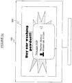
- the client 113 determines via the API to the EPG that the television programme currently being viewed is scheduled to run from 8:00pm to 9:00pm. If an Incoming call is signalled over the Internet 101 and received at the network interface 302 during the program, e.g. say at 8:13pm, then the client application 113 will temporarily block the notification of the incoming call until the scheduled finishing time at 9:00pm. A similar process would occur if an incoming IM chat message is received during the programme, Following the scheduled end time of the programme (either at that time or just after), the client application 113 will then take control of the screen 309 in order to display a list 503 of any one or more communication events missed during the programme.
- the list 503 preferably comprises a control such as a cursor 505 which can be controlled by the user, e.g. via function buttons 208 on the remote control, to thereby operate the client 113 initiate a return VoIP call or other corresponding packet-based communication with the respective other user.
- a control such as a cursor 505 which can be controlled by the user, e.g. via function buttons 208 on the remote control, to thereby operate the client 113 initiate a return VoIP call or other corresponding packet-based communication with the respective other user.
- the programme timing information 603 may comprise a real-time indication of the programme's actual end time (which can be accessed by the client via the API to the television application in a similar manner as discussed above).
- the client 113 will not display the list 503 of missed events until the actual end time of 9:02pm. This advantageously avoids the deferred notifications interfering with the last few minutes of a programme (which could even be the most critical part of the programme in the case of a suspense drama for instance), The client 113 will also defer any incoming communications received during the overrunning period (e.g. at 9:01pm).
- the real-time programme timing information may also indicate the time of breaks in the programme (typically used as commercial breaks to show advertisements, but potentially also used for other purposes such as news bulletins), In this case the client application 113 will be enabled to display the list of missed events 503 during the break.
- a second mechanism for delineating the programme is for the client application 113 to download programme timing information via the Internet 101 and network interface 302, e.g. from a server of a broadcaster, programme production company or third-party service.
- This downloaded information could comprise either schedule information and/or real-time updates to the scheduled times,
- This second mechanism has the advantages of the first mechanism, with the added advantage of being compatible with legacy technologies in which certain timing information 603 may not be available via the broadcast (most digital television broadcasts nowadays do at least include schedule information such as the EPG, but do not all necessarily provide real-time indications of programme timing, and furthermore analogue broadcasts do not include any programme timing information), This could even be used in conjunction with the former variant of the first mechanism in order to provide updates to the schedule information received in the broadcast 603,
- a third, less preferred mechanism for delineating the programme is to provide a timer that can be set by the user,
- the timer may be a feature of the client application 113, or be a feature of the television application 330 which may be accessed via the APIs.
- the user sets the timer for a predetermined time, and the client application 113 waits until that time before displaying the list of missed events 503.
- the third mechanism has the downside of possible interference with the end of an overrunning program, and also has the added downside of requiring an inconvenient user input process.
- this third mechanism has the advantage of being compatible with legacy technologies such as analogue broadcasts which do not include programme timing information, and without requiring additional server infrastructure to provide such information via the internet 101.
- a fourth mechanism would be to provide a user-defined "do not disturb” (DND) setting which the client could assert at the beginning of the programme.
- DND do not disturb
- the client application 113 may be necessary for the client application 113 to monitor the current time. This could be done based on a local clock 340, or by receiving updates of the current time from the Internet 101 or television network 108. However, using the latter variant of the first mechanism, there may be no need to monitor the current time if the programme timing information 603 provides a real-time trigger (as opposed to a real-time update of the end time in hours and minutes of the day). There will also be no need to monitor the current time in the fourth, DND-based mechanism.
- the client application 113 may be further configured to return automated messages to the callers of the missed calls (or more generally to the other users who are the originators of the missed communication events).
- the automated message is returned by the client application 113 when an incoming communication event is received during an ongoing programme, without requiring an input from the local user viewing the programme (the callee). It Is transmitted to the other, remote user (the caller) via the network interface 302 and Internet 101, and informs the caller that the callee is unavailable.
- the automated message indicates to the caller the reason why the callee is unavailable (watching TV).
- the client application 113 may be configured to use the programme schedule or other timing information to predict when the callee is likely to become available again (i.e. when the current programme is due to finish), and may include this predicted information in the automated message for the benefit of the caller. This could even be incorporated as a new kind of presence status.
- the invention is not limited to on-screen notifications.
- the notifications may comprise audible notifications output via a speaker, and it may desirable to defer the audible notifications so that they do not disrupt the user's experience of a current television programme.
- notifications could be deferred until the user changes channel, changes to a different source such as from television programmes to AV input 308, or accesses the EPG.
- the client could access the decoded audio via an API to the television application 330 and attempt to determine when a commercial break occurs based on a change in peak or average volume levels (broadcasters tend to increase the volume during commercial breaks to get the user's attention, though this method would be vulnerable to false alarms e.g. during action sequences of a programme).
- programme does not limit to any particular kind of programme content, and could refer for example to a film, soap opera, documentary, sporting event, news program, etc.
- DSPs dedicated signal processors
- the client application and television application could each be run on a different respective CPU embedded in the television set 103.
- Some or all of the functionality of the television application 330 could alternatively be implemented in dedicated hardware, including the possibility of hardwired signal processing apparatus in the television receiver front-end 304.
- the technique described above is not limited to use in a television set having the above components including television screen all within one single self-contained casing.
- the technique could be implemented in a set-top box for plugging into such a television set.
- the diagram would be similar to that of Figure 3a but with the television hardware 320, 322, 324 and screen 309 replaced by an audio-video (AV) output.
- AV audio-video
- the client application 113 is installed on a games console 105.
- the console 105 comprises a processing apparatus 301 in the form of one or more CPUs, coupled to: a non-volatile storage means 318 such as hard drive, flash memory and/or optical disc drive; a RAM 319; a webcam or input 308 from a webcam; and a network interface 302 such as a wi-fi transceiver for accessing a packet-based network such as the Internet 101 (e.g. via wireless router 303).
- the processing apparatus 301 is further coupled to dedicated gaming graphics hardware 325 and dedicated audio hardware 327, which in turn connect to an audio-video (AV) output 307 for connecting the console 105 to a television set 103.
- the processing apparatus 301 is further coupled to an additional wireless interface 315 operating on a band suitable for communicating to and from a wireless gamepad 317 or other such game controller (or alternatively a wired interface could be provided).
- the non-volatile storage 318 supplies the client application 113 and a video game 331 (not necessarily from the same storage unit or medium), both arranged for execution on the processing apparatus 301 (preferably under control of an operating system 326).
- the video game comprises a console library arranged to handle the I/O with the various devices 315, 325, 327 and 308; a game engine arranged to perform the underlying game logic, and a game UI layer arranged to generate game graphics and sound for output via the console library and graphics and sound hardware 325, 327.
- the video game 331 also comprises an API for communicating with the API of the client application 113 via the OS 326.
- the APIs may be used to signal occurrences within the video game 331 to the client 113, and these signalled occurrences may be used by the client 113 to delineate the video game for the purpose of deferring notifications. For example, notifications of an incoming call could be deferred until a player dies or loses within the video game. This may be a more suitable juncture to notify the user than mid-game when he or she may not wish to be distracted.
- the video apparatus may comprise any combination of dedicated hardware and/or regions of memory storing software modules, with any software modules being executed on either the same or a different processor unit as the client application 103.
- the video apparatus may take different forms.
- the video apparatus may be said to comprise a combination of the frame buffers 320 and 322, video hardware 324, and/or a region of the non-volatile memory 318 storing signal processing code of the television application.
- the video apparatus may be said to comprise the video hardware 325, external AV output 307, and/or a region of the non-volatile storage 318 storing graphics processing code of the video game 331.
- the present invention is not limited particularly to VoIP or to a peer-to-peer topology.
- Other packet-based networks, protocols and methods of call set-up may also be used.
Description
- The present invention relates to a games console comprising processing apparatus for conducting voice or video calls via a packet-based network and a method of operating such a games console.
- Some communication systems allow the user of a terminal, such as a personal computer, to conduct voice or video calls over a packet-based computer network such as the Internet. Such communication systems include voice or video over internet protocol (VoIP) systems. These systems are beneficial to the user as they are often of significantly lower cost than conventional fixed line or mobile networks. This may particularly be the case for long-distance communication. To use a VoIP system, the user installs and executes client software on their terminal. The client software sets up the VoIP connections as well as providing other functions such as registration and authentication. In addition to voice communication, the client may also set up connections for other communication media such as instant messaging ("IM"), SMS messaging, file transfer and voicemail.
- One type of communication system for packet-based communication uses a peer-to-peer ("P2P") topology. To enable access to a peer-to-peer system, a user executes P2P client software supplied by a P2P software provider on their terminal, and registers with the P2P system. When the user registers with the P2P system, the client software is provided with a digital certificate from a server. This may be referred to as a "user identity certificate" (UIC). Once the client software has been provided with the certificate, then calls or other communication connections can subsequently be set up and routed between end-users ("peers") of the P2P system without the further use of a server in the call set-up. Instead, the client looks up the required IP addresses from information distributed amongst the P2P client software on other end-users' terminals within the P2P system. That is, the address look-up list is distributed amongst the peers themselves. Once the IP address of a callee's terminal has thus been determined, the caller's P2P client software then exchanges UIC certificates with the callee's P2P client software. The exchange of these digital certificates between users provides proof of the users' identities and that they are suitably authorised and authenticated in the P2P system. Therefore the presentation of digital certificates provides trust in the identity of the users.
- It is therefore a characteristic of peer-to-peer communication that, once registered, the users can set up their own communication routes through the P2P system in at least a partially decentralized manner based on distributed address look-up and/or the exchange of one or more digital certificates, without using a server for those purposes. Further details of an example P2P system are disclosed in
WO 2005/008524 andWO 2005/009019 . - VoIP or other packet-based communications can also be implemented using non-P2P systems that do use centralized call set-up and/or authorisation, e.g. via a server.
- A problem with packet-based communications is that their accessibility to users is limited. In particular, such communications are most commonly accessed using a personal computer. This has the disadvantage that the user must be sufficiently technically competent to download, install and operate the packet-based communication client software on their personal computer, which provides a barrier to the take-up. Even when the communication client is installed and executed on a personal computer, its use may be limited because personal computers are often not located in a place where the user is either familiar or comfortable with communicating. For example, a personal computer is often located in a study which for many users is not the most natural or comfortable environment for making phone calls.
- Whilst packet-based communication systems can also be accessed via certain mobile devices, these generally do not have processing resources or display screens available to offer a full range of features, such as video calling.
- It would therefore be desirable to make packet-based communications more accessible to users. One way to do this would be to run a packet-based communication client on a processor embedded in a familiar household media appliance like a television set or set-top box for plugging into a television. Embedded in this context means within the casing of the appliance. The ability to integrate an embedded processor into a television set or set-top box is known, and indeed many modern televisions and boxes already contain a processor for performing at least some of the digital signal processing required to decode and output viewable television signals to the screen.
-
EP 2 114 062 A1 - However, the inventors have recognised that one or more potential problems may still exist due to a conflict between the added functionality of the client application and the existing functionality of a conventional television.
- Particularly, operation of the client is likely to interfere with the user's viewing, because incoming calls will be asynchronous with the current state of the television. That is to say, the calls are not chosen to be initiated by the user of the television, but instead arrive over the packet-based network at unpredictable times at the initiation of another, remote user, and therefore may arrive when the television is occupied with viewing content from a games console.
- According to one aspect of the present invention, there is provided a games console according to
claim 1 and/or a method of operating a games console according toclaim 7. - Thus, embodiments of the present invention automatically defer notifications of incoming calls or other communications until after a suitable juncture in the video game, prompting the user with the notifications once that time has been reached. This means a user will not be unduly disturbed by asynchronous incoming communication events during the video game in question, but instead will be prompted about those communication events later at a more suitable time.
- The incoming communication events may comprise an incoming packet-based voice or video call.
- The client application may be configured to detect said delineation based on a timer set by the user.
- The client application may be configured to detect said delineation based on a user input indicating the delineation.
- The notification may take the form of either audible and/or on-screen notifications. Therefore in further embodiments the client application may be configured to output the one or more deferred notifications for display on the screen.
- Furthermore, the client application may be configured to output the one or more deferred notifications for display on the screen along with an on-screen control allowing the user to initiate a return communication with a corresponding other user via the packet-based network.
- This advantageously facilitates more efficient return of the call or other communication.
- In further embodiments the client application may be configured to return, prior to said delineation, an automated message to the one or more other users of the one or more incoming communication events received during the video game.
- Thus, it is possible not only to defer a notification until after the delineation, but also to inform the other, remote user about the lack of availability. In a further embodiment the communication client may comprise a user-setting arranged to toggle between a first mode of operation in which notifications of incoming communication events received during the video game are deferred, and a second mode of operation in which such notifications are not deferred and are instead output to the user during the video game.
- The client application may be configured to detect said delineation when a player dies or loses within the video game.
- In embodiments the method may further comprise in accordance with any of the above features of the games console.
- For a better understanding of the present invention and to show how it may be put into effect, reference is made by way of example to the accompanying drawings in which:
-
Figure 1 is a schematic representation of a communication system, -
Figure 2 is a schematic representation of a remote control unit, -
Figure 3a is a schematic block diagram of a television set outside the scope of the present claims, -
Figure 3b is a schematic block diagram of a games console according to an embodiment of the present invention, -
Figure 4 is a schematic representation of a user interface, and -
Figure 5a is a schematic representation of a deferred call notification, -
Figure 5b is a schematic representation of another deferred call notification, -
Figure 5c is a schematic representation of another deferred call notification, and -
Figure 6 schematically illustrates transmission of a transport stream. - An embodiment of the invention will be described with reference to
Figure 3b . However, to assist in the description of that embodiment, arrangements outside the scope of the present claims will be described first, with reference toFigures 1 ,2 and3a . -
Figure 1 shows acommunication system 100 comprising a packet-basednetwork 101 such as the Internet; and further comprising a separatetelevision broadcasting network 108 such as a terrestrial, satellite or cable television network. A plurality ofcomputer terminals 102 are shown coupled to theInternet 101, each comprising a network interface for communicating over the Internet. A plurality oftelevision sets 103 are also shown coupled to theInternet 101, each of which also comprises a network interface for communicating over the Internet. In addition to the network interface, eachtelevision set 103 further comprises a television receiver for receiving analogue and/or digital television signals which are broadcast over thetelevision network 108. Alternatively or additionally, atelevision set 103 could be arranged to receive packet-based television signals over theInternet 101 or other such packet-based network.
The difference between a broadcast and a communication made over a packet-based network is that broadcast signals are transmitted indiscriminately, without transmitting to selected destination devices and regardless of whether the end-user has selected to receive the signal (although a decryption key or such like may still be required so that only authorised users can derive meaningful information from the television signal for viewing). Packet-based communications on the other hand are point-to-point, with an address of the intended destination device being included in the packets. In the case of packet-based television signals transmitted over the Internet, these are still point-to-multipoint communications rather than a broadcast. - Each
computer terminal 102 is installed with a communication client application 110, Eachcomputer terminal 102 also comprises anaudio transceiver 111 comprising a speaker and microphone, e.g. in the form of a headset or handset, or a built-in speaker and microphone.Most computer terminals 102 preferably also comprise awebcam 112. Furthermore, eachtelevision set 103 comprises an embedded processor and memory installed with a version of thecommunication client application 113 specially adapted for running on a television set. Eachtelevision set 103 also comprises awebcam 115 and an audio transceiver with speaker and microphone, or is connected or communicable with such components. An audio transceiver may be provided in aremote control unit 114 of thetelevision 103, discussed shortly. - The
communication client applications 110 and 113 are preferably peer-to-peer clients for setting-up and conducting VoIP calls according to peer-to-peer principles as discussed above. To that end, a peer-to-peer backend server 104 is coupled to theInternet 101 for receiving registration requests from theclient applications end server 104 is arranged to distribute UIC certificates to therespective client applications computer terminals 102 andtelevision sets 103 in response to the registration requests. Once registered and thus in possession of a UIC certificate, theclient applications 111 and/or 113 can look-up one another's addresses, exchange and authenticate one another's certificates, and thus establish a voice or video call over theInternet 101. It will be appreciated however that other kinds of communication client could alternatively be used, e.g. based on centralized server-based call set-up. - In addition, the
communication system 100 may comprise atelephone network 107 such as a circuit-switched network, and agateway 106 connecting between theInternet 101 and thetelephone network 107. A gateway version of the client application is arranged to run on thegateway 106, and acommunication client application 110 or 113 running on acomputer terminal 102 ortelevision set 103 is thus able to establish a call with adedicated phone unit 109 of thetelephone network 107. This is achieved by establishing a connection with the client on thegateway 106 using peer-to-peer call set-up and then supplying the relevant telephone number to the gateway 107 (effectively the user'sclient 110 or 113 sees thegateway 106 as a peer). Thephone network 107 may for example comprise a fixed-line network ("landline") and/or a mobile cellular network. - Each
television set 103 has an associatedremote control unit 114, an example of which is illustrated inFigure 2 . - As shown in
Figure 2 , the remote control unit (or just "remote control") comprises amicrophone 201,speaker 202, a first remote interface in the form of an infrared (IR)transmitter 203, and a second remote interface in the form of a short-range RF interface 204 such as a Bluetooth interface. Themicrophone 201 andspeaker 202 are operatively coupled to theBluetooth interface 204. Theremote control 114 is thus arranged to communicate voice signals from themicrophone 201 to thetelevision 103 via theBluetooth interface 204, and to receive voice signals from thetelevision 103 via theBluetooth interface 204 for playing out of thespeaker 202. - The
remote control 114 further comprises a plurality of buttons operatively coupled to theinfrared transmitter 203, arranged so as to allow the user to control thetelevision 103 via theinfrared transmitter 203. The buttons comprise a "standby"button 205 for setting the television into a low-power mode. The buttons further comprise numerical oralphanumeric buttons 206 for changing channel or supplying other numerical or alphanumerical data to thetelevision 103;function buttons 208 for controlling various functions of thetelevision 103, e.g. for controlling a cursor and/or menu system; and optionally dedicated calling buttons 207 for performing specific dedicated operations relating to the calling functionality of theclient application 113, e.g. "call", "hang up", or buttons for zooming in and out during a video call. -
Figure 3a is a schematic block diagram of atelevision set 103 outside the scope of the present claims. Thetelevision set 103 is a dedicated television unit in the sense that its primary purpose is as a television, and is designed to fulfil the role of a family or household television. However, at the same time it is additionally provided with secondary embedded functionality such as VoIP calling. - The
television set 103 comprises, within a single casing: an embeddedprocessing apparatus 301; a random access memory (RAM) 319; and an embeddednon-volatile storage device 318 which may comprise an electronically erasable and reprogrammable memory (EEPROM or "flash" memory), a magnetic storage medium, and/or a one-time writable ROM. Thenon-volatile storage device 318 is coupled to theprocessing apparatus 301 and stores a basic operating system (OS) 326, atelevision application 330, and acommunication client application 113 such as a VoIP client. Theprocessing apparatus 301 is arranged to execute theoperating system 326, e.g. either by fetching instructions directly from ROM or by first loading from a flash memory into theRAM 319 before fetching. When executed, theoperating system 326 is configured to load thetelevision application 330 andclient application 113 intoRAM 319 and schedule them for execution on theprocessing apparatus 301. Theprocessing apparatus 301 is thus arranged to run thetelevision application 330 andclient application 113 under control of theoperating system 326. In some examples, only aminimal operating system 326 may be required, in the form of a basic scheduler. - The
television set 103 further comprises, within the same casing: avideo frame buffer 320 and user interface (Ul)frame buffer 322,video hardware 324, ascreen 309, anamplifier 314 andspeaker 316 or output to an external speaker or headphones, atelevision receiver 304, an external audio-video (AV)input 306 such as a SCART or HDMI input from an external source, a webcam orwebcam input 308 for connecting to an external webcam, anetwork interface 302 in the form of a first short-range RF transceiver such as a wi-fi transceiver, a first remote interface 310 in the form of an infrared (IR) receiver, and a second remote interface in the form of a second short-range RF transceiver 312 such as a Bluetooth transceiver. - The
video frame buffer 320 and user interface (Ul)frame buffer 322 each have an input coupled to theprocessing apparatus 301. Thevideo hardware 324 has an input coupled to the outputs of thevideo frame buffer 320 andUI frame buffer 322. Thescreen 309 has an input to the output of thevideo hardware 324. The frame buffers 320 and 322 could be dedicated hardware buffers or alternatively could be implemented in a general purpose memory. Theamplifier 314 has an input coupled to theprocessing apparatus 301 and an output coupled to thespeaker 316. Theprocessing apparatus 301 is further coupled to thenetwork interface 302,television receiver 304,auxiliary input 306,webcam input 308, infrared interface 310, andBluetooth interface 312. - Any or all of the above components may be coupled to the
processing apparatus 301 via intermediate components such as a bus and/or cache (not shown), as will be understood by a person skilled in the art. - The
television receiver 304 comprises an input for connecting to at least one reception means such as an antenna, satellite dish or cable line, and is thus arranged to receive television broadcast signals from thetelevision network 108 via the reception means. Thetelevision receiver 304 is a hardware front-end which may comprise for example: sampling circuitry, a low noise amplifier, a filter, a mixer, and/or an analogue-to-digital converter (ADC). Once received by thetelevision receiver unit 304, the television signals are thus made available to theprocessing apparatus 301 for signal processing. Thetelevision application 330 comprises a signal processing engine in the form of code which, when executed, performs at least some of the required signal processing on the received television signals. The processed television signals are then output to thevideo frame buffer 320 andamplifier 314 for consumption by the end user. The signal processing engine may comprise for example: a digital filter, demodulator, demultiplexer, decoder, decryption block, and/or error checking block. However, different ways of allocating the television receiver and processing functionality between software and dedicated hardware are also possible. E.g. more of the functionality such as the demultiplexing could be moved to the receiver front-end 304. Techniques for receiving and processing television signals will be known to a person skilled in the art. - In the case of traditional analogue television broadcasts, the signals of a plurality of different concurrent programs (of different TV channels) are frequency-division multiplexed over the airwaves by being transmitted on different frequencies. The
television receiver 304 will then comprise a tuning circuit to demultiplex the broadcasts and thereby separate out the signal of the required programme, In the case of digital television broadcasts, the signals of different concurrent programs are each divided into packets and interleaved so as to time-division multiplex the different programs' signals into a transport stream for broadcast. The signal processing engine of thetelevision application 330 will then comprise a packet filter to demultiplex the packets of different transport streams and so separate out the signal of the required programme. Multiple transport streams may also be broadcast on different frequencies, requiring a tuner as well. Furthermore, for digital television, one or more of the transport streams may comprise additional programme information such as an electronic programme guide (EPG). - Video signals for output to the
television screen 309 may also be received via theAV input 306 from an external source such as a DVD player or games console. - The
television application 330 further comprises a UI graphics engine, a remote protocol engine, an application programming interface (API), and a television UI layer. The overall operation of the signal processing engine, UI graphics engine, remote protocol engine and API is controlled by the television UI layer. The user can select which broadcast to view by pressingbuttons remote control 114, causing theremote control 114 to communicate control signals to theprocessing apparatus 301 via theinfrared transmitter 203 and receiver 310. The user may also use the buttons in a similar manner to view additional information such as the EPG or control menus, and to navigate the EPG or menus. The relevant control signals are interpreted by the remote protocol engine of thetelevision application 113, which in turn communicates with the television UI layer. In response, the television UI layer controls the signal processing engine to output the relevant television programme to thevideo frame buffer 320, and/or controls the UI graphics engine to output graphics to the UI frame buffer 322 (e.g. to display the graphics of the menu or EPG). The frame buffers 320 and/or 322 supply their contents to thevideo hardware 324 for display on thescreen 309. TheUI frame buffer 322 andvideo hardware 324 may be arranged to overlay UI graphics over the current television programme in a partially transparent manner, and/or to leave at least part of the television programme visible. - As mentioned, the
television set 103 comprises anetwork interface 302. Thisnetwork interface 302 may take the form of a wireless transceiver such as a wi-fi transceiver, for communicating wirelessly with a household or office-basedwireless router 303 as found in most modern homes or offices. Therouter 303 in turn connects to theInternet 101. However, alternatively, thenetwork interface 302 may comprise other options such as a wired modem or a port to an external wired modem. - The
communication client application 330 comprises a protocol stack having an I/O layer which, when executed on theprocessing apparatus 301, is operable to transmit and receive signals over theInternet 101 via thenetwork interface 302. The I/O layer comprises a network signalling protocol for transmitting and receiving control signals over theInternet 101 via thenetwork interface 302. The I/O layer may also comprise an API for communicating with the API of thetelevision application 301. - The I/O layer further comprises a voice engine comprising a voice codec. The voice engine is arranged to accept speech signals from the
microphone 201, and to encode those speech signals for transmission over theinternet 101 via thenetwork interface 302. The voice engine is also arranged to decode speech signals received over theInternet 101 via thenetwork interface 302, for output to the television'samplifier 314 andspeaker 316, or to thespeaker 202 in theremote control 114 via the Bluetooth interfaces 312 and 204. The I/O layer further comprises a video engine comprising a video codec. The video engine is arranged to accept video signals from thewebcam input 308, and to encode those video signals for transmission over theInternet 101 via thenetwork interface 302. The video engine is also arranged to decode video signals received over theInternet 101 via thenetwork interface 302, for output to theUI frame buffer 322,video hardware 326 andscreen 309. Alternatively, in a full-screen mode the video codec could output video via thevideo frame buffer 320. - Higher up the protocol stack, the
client application 113 comprises a client engine which is responsible for call-set up. The client engine controls the network signalling protocol engine of theclient 113 in order to establish a live voice or video call with anotheruser terminal Internet 101, preferably using P2P call set-up as discussed above, or potentially using a centralized call set-up via a server. The client engine may also handle other functions such as connection management, authentication, encryption, and/or exchanging presence information with theclient applications - Even higher up the protocol stack, the
client application 113 comprises a client UI layer which is responsible for the client's user interface. The client UI layer is operable to generate a client user interface for output to theUI frame buffer 322,video hardware 324 andscreen 309. This may be output via the APIs and the UI graphics engine of theTV application 330 under control of the TV UI layer (or alternatively theclient application 113 could be provided with its own UI graphics protocol to output graphics to theUI frame buffer 322 directly). The client user interface thus presents the user with on-screen controls which they can activate usingbuttons remote control 114. Based on these button presses, theremote control 114 communicates control signals to theprocessing apparatus 301 via theinfrared transmitter 203 and receiver 310. These control signals may be interpreted by the UI protocol engine in thetelevision application 330 and then signalled via the APIs to the I/O layer of the client application 113 (or alternatively the I/O layer of theclient application 113 could be provided with its own remote control protocol to interpret these control signals directly). In turn, the protocol of the I/O layer of theclient 113 communicates with the client UI layer. The client Ul layer is thus configured to respond to user inputs in order to control the overall operation of theclient application 113, e.g. allowing a user to select contacts to call, hang up, etc. -
Figure 4 illustrates an example user interface which could be displayed on thescreen 309 by theclient application 113, when summoned by the user using the relevant buttons of the remote 114. The user interface may be displayed only on part of thescreen 309, allowing at least a portion of a currently viewed programme to remain visible; or may alternatively take up thewhole screen 309. The displayed user interface comprises a number of panels. For example, the user interface may comprise afirst panel 402 showing profile information of the user of thetelevision 103 on which theclient 113 is running. E.g. the profile information may comprise the user's name, an "avatar image" (a picture which the user has chosen to represent themselves), and/or a "mood message" (a short user-defined statement for inclusion in their profile). Further, the user interface may comprise asecond panel 404 showing a list of the user's contacts (preferably theclient 113 is configured to only allow calls between users who have agreed to be contacts). Further, the user interface may comprise athird panel 406 showing a profile of a selected one of the contacts, and/or afourth panel 408 providing a menu or other controls for selecting to call the selected contact. - Furthermore, the UI layer of the
client 113 may be configured to communicate with the UI layer of thetelevision application 330, via the APIs and theoperating system 326. This allows theclient application 113 andtelevision application 330 to negotiate control of thescreen 309 and/orspeaker - Whether the
client application 113 ortelevision application 330 takes precedence may depend on the implementation and/or situation. Since thetelevision set 103 is primarily a television, then preferably theclient application 113 should require permission from thetelevision application 330 before controlling thescreen 309 orspeaker client application 113 can autonomously take control of thescreen 309 and/orspeaker non-volatile memory 318 and be readable by theclient application 113 and/ortelevision application 330. E.g. thetelevision application 330 may be configured to read a setting from memory and, if set, to unequivocally allow theclient application 113 to control the screen and/or speaker. Alternatively theclient application 113 may be configured to read a setting from memory and, if set, to control the screen and/or speaker without seeking permission from thetelevision application 330. - At least one such user setting may be read by the
client application 113, and when set theclient application 113 is configured to defer any notifications of incoming VoIP calls or other incoming communication events received over theInternet 101 until a suitable juncture in the user's television viewing. This could mean deferring a notification until after a television programme is finished, or until some other suitable juncture in the programme such as a commercial break. Another possibility would be to defer a notification until after video signals cease to be received via theAV input 306 from an external source such as DVD player or games console. Generally speaking, incoming communication events signalled asynchronously to thetelevision set 103 over theInternet 101 via thenetwork interface 302 are postponed in deference to a higher-priority source such as thetelevision receiver 308 andtelevision network 108, orAV input 306 and external source. - Note that the concept of deferring a notification is distinct and advantageous over the mere outright suppression of a notification. Suppressing the notification would mean barring it altogether so as never to be output to the user; whereas deferral requires that the notification will still output to the user, but postponed until some later point in time.
- In order to do this, the
client application 113 is configured with a mechanism for delineating the viewing activity in question. Theclient application 113 will not understand the actual user content of the television programme or such like, so cannot directly tell when one programme ends and another begins, or cannot directly tell the difference between the main programme and the commercial breaks. Therefore a delineation mechanism is required, for which there are a number of options as discussed below. - A first, preferred mechanism involves receiving additional programme information broadcast over the
television network 108. In this case the additional programme information is received by theclient application 113 via thetelevision receiver 308, and comprises timing information which can be used by theclient application 113 to delineate the television programme for the purpose of deferring notifications. - As illustrated schematically in
Figure 6 , a digital television broadcast may compriseaudio data 601 andvideo data 602 of one or more programme streams all interleaved together (i.e. time-division multiplexed) into a combined transport stream for transmission on a particular frequency. Also interleaved into the transport stream isadditional program information 603 providing timing information for the one or more programmes (potentially amongst other information such as subtitles and textual programme summaries or precis). Theadditional programme information 603 may take the form of a general data stream multiplexed into the transport stream in conjunction with a plurality of programme streams, providing programme information for a plurality of programmes. An example of this would be an electronic program guide (EPG). Alternatively or additionally, individual respective programme information may be provided in the stream of each programme, The audio data, video data and additional programme information are decoded by the signal processing engine of thetelevision application 331, and the required programme timing information can be accessed by theclient application 113 via the APIs under control of the TV UI layer, - In one variant of this first mechanism, the
programme timing information 603 comprises programme schedule information such as the EPG. That is, nominal information about when the programme or programmes are scheduled to start and end. For example, the API of theclient application 113 may enable it to access the EPG decoded by the signal processing engine of thetelevision application 331. Theclient 113 can thereby determine that the television programme currently being viewed on thescreen 309 is scheduled to end at a particular time, and defer the notification until that time. - An example is shown in
Figure 5a . Here, theclient 113 determines via the API to the EPG that the television programme currently being viewed is scheduled to run from 8:00pm to 9:00pm. If an Incoming call is signalled over theInternet 101 and received at thenetwork interface 302 during the program, e.g. say at 8:13pm, then theclient application 113 will temporarily block the notification of the incoming call until the scheduled finishing time at 9:00pm. A similar process would occur if an incoming IM chat message is received during the programme, Following the scheduled end time of the programme (either at that time or just after), theclient application 113 will then take control of thescreen 309 in order to display alist 503 of any one or more communication events missed during the programme. Thelist 503 preferably comprises a control such as acursor 505 which can be controlled by the user, e.g. viafunction buttons 208 on the remote control, to thereby operate theclient 113 initiate a return VoIP call or other corresponding packet-based communication with the respective other user. - In another variant of the first mechanism, the
programme timing information 603 may comprise a real-time indication of the programme's actual end time (which can be accessed by the client via the API to the television application in a similar manner as discussed above). - As shown in
Figure 5b , if the programme overruns until a later time than scheduled, e.g. say 9:02pm, then theclient 113 will not display thelist 503 of missed events until the actual end time of 9:02pm. This advantageously avoids the deferred notifications interfering with the last few minutes of a programme (which could even be the most critical part of the programme in the case of a suspense drama for instance), Theclient 113 will also defer any incoming communications received during the overrunning period (e.g. at 9:01pm). - Further, as shown in
Figure 5c , the real-time programme timing information may also indicate the time of breaks in the programme (typically used as commercial breaks to show advertisements, but potentially also used for other purposes such as news bulletins), In this case theclient application 113 will be enabled to display the list of missedevents 503 during the break. - A second mechanism for delineating the programme is for the
client application 113 to download programme timing information via theInternet 101 andnetwork interface 302, e.g. from a server of a broadcaster, programme production company or third-party service. This downloaded information could comprise either schedule information and/or real-time updates to the scheduled times, This second mechanism has the advantages of the first mechanism, with the added advantage of being compatible with legacy technologies in whichcertain timing information 603 may not be available via the broadcast (most digital television broadcasts nowadays do at least include schedule information such as the EPG, but do not all necessarily provide real-time indications of programme timing, and furthermore analogue broadcasts do not include any programme timing information), This could even be used in conjunction with the former variant of the first mechanism in order to provide updates to the schedule information received in thebroadcast 603, - A third, less preferred mechanism for delineating the programme is to provide a timer that can be set by the user, The timer may be a feature of the
client application 113, or be a feature of thetelevision application 330 which may be accessed via the APIs. In this arrangement, the user sets the timer for a predetermined time, and theclient application 113 waits until that time before displaying the list of missedevents 503. This would have a similar effect as shown inFigure 5a . As with the former variant of the first mechanism, the third mechanism has the downside of possible interference with the end of an overrunning program, and also has the added downside of requiring an inconvenient user input process. On the other hand this third mechanism has the advantage of being compatible with legacy technologies such as analogue broadcasts which do not include programme timing information, and without requiring additional server infrastructure to provide such information via theinternet 101. - A fourth mechanism would be to provide a user-defined "do not disturb" (DND) setting which the client could assert at the beginning of the programme. This could be an existing DND presence status available within the
client application 113, In this case theclient application 113 is configured to detect when the user de-asserts the DND status, and upon detecting this to automatically display the list of missedevents 503. - In some of the above mechanisms it may be necessary for the
client application 113 to monitor the current time. This could be done based on alocal clock 340, or by receiving updates of the current time from theInternet 101 ortelevision network 108. However, using the latter variant of the first mechanism, there may be no need to monitor the current time if theprogramme timing information 603 provides a real-time trigger (as opposed to a real-time update of the end time in hours and minutes of the day). There will also be no need to monitor the current time in the fourth, DND-based mechanism. - In a particularly advantageous addition to the present invention, the
client application 113 may be further configured to return automated messages to the callers of the missed calls (or more generally to the other users who are the originators of the missed communication events). The automated message is returned by theclient application 113 when an incoming communication event is received during an ongoing programme, without requiring an input from the local user viewing the programme (the callee). It Is transmitted to the other, remote user (the caller) via thenetwork interface 302 andInternet 101, and informs the caller that the callee is unavailable. Preferably the automated message indicates to the caller the reason why the callee is unavailable (watching TV). In one particularly preferred embodiment, theclient application 113 may be configured to use the programme schedule or other timing information to predict when the callee is likely to become available again (i.e. when the current programme is due to finish), and may include this predicted information in the automated message for the benefit of the caller. This could even be incorporated as a new kind of presence status. - The invention is not limited to on-screen notifications. The notifications may comprise audible notifications output via a speaker, and it may desirable to defer the audible notifications so that they do not disrupt the user's experience of a current television programme.
- The arrangements described above are not limited to any particular mechanism for delineating a television program or other viewing activity. A number of examples have been described above, and others may become apparent to a person skilled in the art given the disclosure herein. For example, in an arrangement outside the scope of the present claims, notifications could be deferred until the user changes channel, changes to a different source such as from television programmes to
AV input 308, or accesses the EPG. In another example outside the scope of the present claims, the client could access the decoded audio via an API to thetelevision application 330 and attempt to determine when a commercial break occurs based on a change in peak or average volume levels (broadcasters tend to increase the volume during commercial breaks to get the user's attention, though this method would be vulnerable to false alarms e.g. during action sequences of a programme). - Note also that the term "programme" does not limit to any particular kind of programme content, and could refer for example to a film, soap opera, documentary, sporting event, news program, etc.
- Further, other ways of allocating the various client, television and other functionality amongst different processors are envisaged. For example, one or more dedicated signal processors (DSPs) could be arranged to execute the television signal processing engine of the
television application 330 and/or the video engine and/or voice engine of theclient application 113; with one or more separate CPUs being arranged to execute the UI layer, client engine, protocol and graphics engines of theclient application 113 and/or the UI layer and protocol and graphics engines of thetelevision application 330. In another example, the client application and television application could each be run on a different respective CPU embedded in thetelevision set 103. Some or all of the functionality of thetelevision application 330 could alternatively be implemented in dedicated hardware, including the possibility of hardwired signal processing apparatus in the television receiver front-end 304. - Furthermore, although the preferred application, the technique described above is not limited to use in a television set having the above components including television screen all within one single self-contained casing. In another example outside the scope of the present claims, the technique could be implemented in a set-top box for plugging into such a television set. In that case the diagram would be similar to that of
Figure 3a but with thetelevision hardware screen 309 replaced by an audio-video (AV) output. - In an example embodiment of the present invention, illustrated in
Figure 3b , theclient application 113 is installed on agames console 105. Similarly to thetelevision 103, theconsole 105 comprises aprocessing apparatus 301 in the form of one or more CPUs, coupled to: a non-volatile storage means 318 such as hard drive, flash memory and/or optical disc drive; aRAM 319; a webcam orinput 308 from a webcam; and anetwork interface 302 such as a wi-fi transceiver for accessing a packet-based network such as the Internet 101 (e.g. via wireless router 303). Theprocessing apparatus 301 is further coupled to dedicatedgaming graphics hardware 325 and dedicatedaudio hardware 327, which in turn connect to an audio-video (AV)output 307 for connecting theconsole 105 to atelevision set 103. Theprocessing apparatus 301 is further coupled to anadditional wireless interface 315 operating on a band suitable for communicating to and from awireless gamepad 317 or other such game controller (or alternatively a wired interface could be provided). Thenon-volatile storage 318 supplies theclient application 113 and a video game 331 (not necessarily from the same storage unit or medium), both arranged for execution on the processing apparatus 301 (preferably under control of an operating system 326). The video game comprises a console library arranged to handle the I/O with thevarious devices sound hardware - The
video game 331 also comprises an API for communicating with the API of theclient application 113 via theOS 326. The APIs may be used to signal occurrences within thevideo game 331 to theclient 113, and these signalled occurrences may be used by theclient 113 to delineate the video game for the purpose of deferring notifications. For example, notifications of an incoming call could be deferred until a player dies or loses within the video game. This may be a more suitable juncture to notify the user than mid-game when he or she may not wish to be distracted. - Although the present claims are directed to a games console and a method of operating a games console, generally speaking, the technique can, in examples outside the scope of the present claims, can be applied to any other media appliance having video apparatus for outputting signals to a television screen. The video apparatus may comprise any combination of dedicated hardware and/or regions of memory storing software modules, with any software modules being executed on either the same or a different processor unit as the
client application 103. Depending on the appliance and the implementation, the video apparatus may take different forms. In the television set outside the scope of the present claims, shown inFigure 3a for example, the video apparatus may be said to comprise a combination of theframe buffers video hardware 324, and/or a region of thenon-volatile memory 318 storing signal processing code of the television application. In theexample console 105 of the embodiment shown inFigure 3b , the video apparatus may be said to comprise thevideo hardware 325,external AV output 307, and/or a region of thenon-volatile storage 318 storing graphics processing code of thevideo game 331. - Furthermore, note that the present invention is not limited particularly to VoIP or to a peer-to-peer topology. Other packet-based networks, protocols and methods of call set-up may also be used.
- Other variations of the present invention may be apparent to a person skilled in the art given the disclosure herein. The scope of the present invention is not limited by the described embodiment, but only by the appendant claims.
Claims (12)
- A games console (105) comprising:an audio-video output (307) operable to output video signals of the games console (105) to a television screen (309);a network interface (302) for accessing a packet-based network (101);a memory (318) storing a communication client application (113) and a video game (331), the video game (331) comprising an API for communicating with an API of the communication client application (113);a wireless interface (315) for communicating with a game controller (317); anda processing apparatus (301), coupled to the memory (318), the network interface (302), the audio-video output (307), and the game controller (317), and arranged to execute the communication client application (113) and the video game (331) ;wherein the communication client application (113) is configured to:allow a user to conduct bidirectional communications with other users via the packet-based network (101);receive, from the API of the video game (331), a signal indicating an occurrence within the video game (331);utilize the signal from the API of the video game (331) to identify a delineation within the video game (331); anddefer output of one or more notifications to the user of incoming communication events received, over the packet-based network (101), from one or more of the other users during the video game (331) until the delineation within the video game (331).
- The games console (105) of claim 1, wherein:
the communication client application (113) is further configured to return, prior to said delineation in the video game (331), an automated message to the one or more of the other users from which the incoming communication events originated. - The games console (105) of claim 2, wherein the automated message informs the one or more of the other users from which the incoming communication events originated about the lack of availability of the user.
- The games console (105) of claim 3, wherein the automated message indicates, to the one or more of the other users from which the incoming communication events originated, the reason why the user is unavailable.
- The games console (105) of any of claims 1-4, wherein:
the communication client application (113) is further configured to identify the delineation within the video game (331) based on when a player dies or loses within the video game (331). - The games console (105) of claim 1, wherein:
the communication client application (113) is further configured to output video signals of the one or more of said notifications of incoming communication events to the television screen (309) along with an on-screen control allowing the user to initiate a return communication, via the packet-based network (101), with a corresponding one of the other users from which the incoming communication events originated. - A method for operating a games console (105) having an audio-video output (307) operable to output video signals of the games console (105) to a television screen (309), a network interface (302) for accessing a packet-based network (101), a wireless interface (315), a memory (318) for storing a communication client application (113) and a video game (331), the video game (331) comprising an API for communicating with an API of the communication client application (113), and a processing apparatus (301), coupled to the memory (318), the network interface (302), the audio-video output (307), and the game controller (317), and arranged to execute the communication client application (113) and the video game (331), the method comprising:allowing a user to conduct bidirectional communications with other users via the packet-based network (101);receiving, from the API of the video game (331), a signal indicating an occurrence within the video game (331);utilizing the signal from the API of the video game (331) to identify a delineation within the video game (331); anddeferring output of one or more notifications of incoming communication events received, over the packet-based network (101), from one or more of the other users during the video game (331) until the delineation within the video game (331).
- The method of claim 7, further comprising:
returning, prior to said delineation in the video game (331), an automated message to the one or more of the other users from which the incoming communication events originated. - The method of claim 8, wherein the automated message informs the one or more of the other users from which the incoming communication events originated about the lack of availability of the user.
- The method of claim 9, wherein the automated message indicates, to the one or more of the other users from which the incoming communication events originated, the reason why the user is unavailable.
- The method of any of claims 7-10, further comprising:
identifying the delineation within the video game (331) based on when a player dies or loses within the video game (331). - The method of any of claims 7-11, further comprising:
outputting video signals of the one or more of said notifications of incoming communication events on the television screen (309) along with an on-screen control allowing the user to initiate a return communication, via the packet-based network (101), with a corresponding one of the one or more other users from which the incoming communication events originated.
Priority Applications (1)
| Application Number | Priority Date | Filing Date | Title |
|---|---|---|---|
| EP19186594.8A EP3576395A1 (en) | 2010-03-31 | 2011-03-30 | Media appliance |
Applications Claiming Priority (3)
| Application Number | Priority Date | Filing Date | Title |
|---|---|---|---|
| GBGB1005458.3A GB201005458D0 (en) | 2010-03-31 | 2010-03-31 | Media appliance |
| PCT/EP2011/054881 WO2011121006A1 (en) | 2010-03-31 | 2011-03-30 | Media appliance |
| EP11712236.6A EP2543179B1 (en) | 2010-03-31 | 2011-03-30 | Media appliance |
Related Parent Applications (2)
| Application Number | Title | Priority Date | Filing Date |
|---|---|---|---|
| EP11712236.6A Division-Into EP2543179B1 (en) | 2010-03-31 | 2011-03-30 | Media appliance |
| EP11712236.6A Division EP2543179B1 (en) | 2010-03-31 | 2011-03-30 | Media appliance |
Related Child Applications (1)
| Application Number | Title | Priority Date | Filing Date |
|---|---|---|---|
| EP19186594.8A Division EP3576395A1 (en) | 2010-03-31 | 2011-03-30 | Media appliance |
Publications (2)
| Publication Number | Publication Date |
|---|---|
| EP3229452A1 EP3229452A1 (en) | 2017-10-11 |
| EP3229452B1 true EP3229452B1 (en) | 2019-07-17 |
Family
ID=42228710
Family Applications (3)
| Application Number | Title | Priority Date | Filing Date |
|---|---|---|---|
| EP19186594.8A Pending EP3576395A1 (en) | 2010-03-31 | 2011-03-30 | Media appliance |
| EP11712236.6A Active EP2543179B1 (en) | 2010-03-31 | 2011-03-30 | Media appliance |
| EP16207628.5A Active EP3229452B1 (en) | 2010-03-31 | 2011-03-30 | Games console and method of operating a games console |
Family Applications Before (2)
| Application Number | Title | Priority Date | Filing Date |
|---|---|---|---|
| EP19186594.8A Pending EP3576395A1 (en) | 2010-03-31 | 2011-03-30 | Media appliance |
| EP11712236.6A Active EP2543179B1 (en) | 2010-03-31 | 2011-03-30 | Media appliance |
Country Status (8)
| Country | Link |
|---|---|
| US (4) | US8998720B2 (en) |
| EP (3) | EP3576395A1 (en) |
| CN (2) | CN105915976A (en) |
| DK (1) | DK3229452T3 (en) |
| ES (2) | ES2634035T3 (en) |
| GB (1) | GB201005458D0 (en) |
| PT (1) | PT3229452T (en) |
| WO (1) | WO2011121006A1 (en) |
Families Citing this family (27)
| Publication number | Priority date | Publication date | Assignee | Title |
|---|---|---|---|---|
| GB2475237B (en) * | 2009-11-09 | 2016-01-06 | Skype | Apparatus and method for controlling communication signalling and media |
| GB201005454D0 (en) | 2010-03-31 | 2010-05-19 | Skype Ltd | Television apparatus |
| GB201005465D0 (en) | 2010-03-31 | 2010-05-19 | Skype Ltd | Television set |
| GB2479180B (en) | 2010-03-31 | 2016-06-01 | Skype | System of user devices |
| GB201005458D0 (en) | 2010-03-31 | 2010-05-19 | Skype Ltd | Media appliance |
| US8848934B2 (en) * | 2010-12-08 | 2014-09-30 | Skype | Controlling audio signals |
| US8963982B2 (en) | 2010-12-31 | 2015-02-24 | Skype | Communication system and method |
| US10404762B2 (en) * | 2010-12-31 | 2019-09-03 | Skype | Communication system and method |
| US9717090B2 (en) | 2010-12-31 | 2017-07-25 | Microsoft Technology Licensing, Llc | Providing notifications of call-related services |
| US10291660B2 (en) | 2010-12-31 | 2019-05-14 | Skype | Communication system and method |
| EP2608610A1 (en) * | 2011-12-22 | 2013-06-26 | France Telecom | Method for notifying a user of a device of the occurrence of an event |
| US9019336B2 (en) | 2011-12-30 | 2015-04-28 | Skype | Making calls using an additional terminal |
| US9448685B1 (en) * | 2012-11-20 | 2016-09-20 | Amazon Technologies, Inc. | Preemptive event notification for media experience |
| GB201301452D0 (en) | 2013-01-28 | 2013-03-13 | Microsoft Corp | Providing notifications of call-related services |
| JP6368069B2 (en) | 2013-01-31 | 2018-08-01 | 株式会社ソニー・インタラクティブエンタテインメント | GAME DEVICE, GAME CONTROL METHOD, GAME CONTROL PROGRAM, MATCHING SERVER, MATCHING CONTROL METHOD, AND MATCHING CONTROL PROGRAM |
| US8612534B1 (en) | 2013-01-31 | 2013-12-17 | Electronic Arts Inc. | Pausing of content delivery in push notifications |
| MX2016006493A (en) * | 2013-12-19 | 2017-01-18 | Halliburton Energy Services Inc | Pore size classification in subterranean formations based on nuclear magnetic resonance (nmr) relaxation distributions. |
| US9794783B2 (en) * | 2015-01-16 | 2017-10-17 | Jeffrey Huang | Machine-to-machine visual code generation and recognition method and system for device communications |
| CN104951504B (en) * | 2015-05-20 | 2018-08-14 | 深圳创维-Rgb电子有限公司 | A kind of web page processing method and system |
| US10135941B2 (en) * | 2016-02-18 | 2018-11-20 | International Business Machines Corporation | Managing push notifications on portable devices |
| US20180048921A1 (en) * | 2016-08-12 | 2018-02-15 | Microsoft Technology Licensing, Llc | Real-time playback diagnostics |
| US11241623B2 (en) * | 2017-05-05 | 2022-02-08 | Sony Interactive Entertainment LLC | Instant streaming of a mobile user interface without application install |
| JP6767319B2 (en) * | 2017-07-31 | 2020-10-14 | 株式会社ソニー・インタラクティブエンタテインメント | Information processing device and file copy method |
| US10749828B2 (en) | 2018-03-14 | 2020-08-18 | Rovi Guides, Inc. | Systems and methods for presenting event notifications, based on trending communications, on devices notwithstanding a user instruction to disable event notifications |
| US10491962B2 (en) | 2018-03-14 | 2019-11-26 | Rovi Guides, Inc. | Systems and methods for presenting event notifications, based on active applications in a social group, on devices notwithstanding a user instruction to disable event notifications |
| US10848815B2 (en) * | 2018-08-23 | 2020-11-24 | Dish Network L.L.C. | Outputting a message during downloading or buffering |
| US11325044B2 (en) * | 2019-03-07 | 2022-05-10 | Sony Interactive Entertainment LLC | Video game guidance system |
Family Cites Families (119)
| Publication number | Priority date | Publication date | Assignee | Title |
|---|---|---|---|---|
| US5014125A (en) | 1989-05-05 | 1991-05-07 | Cableshare, Inc. | Television system for the interactive distribution of selectable video presentations |
| US5396546A (en) | 1991-10-03 | 1995-03-07 | Viscorp | Apparatus and method for automatic and user configurable information appliance |
| US5519433A (en) | 1991-11-20 | 1996-05-21 | Zing Systems, L.P. | Interactive television security through transaction time stamping |
| US5988078A (en) | 1991-12-04 | 1999-11-23 | Gemstar Development Corp. | Method and apparatus for receiving customized television programming information by transmitting geographic location to a service provider through a wide-area network |
| US5231198A (en) | 1992-07-06 | 1993-07-27 | Rhone-Poulenc Rorer Pharmaceuticals Inc. | Asymmetric synthesis of hexahydrodibenzofurans by stereospecific inversion of ortho substituted 2-phenylcyclohexanols |
| WO1994006230A2 (en) | 1992-09-02 | 1994-03-17 | Octus, Inc. | Multimedia message transmitter |
| US5600364A (en) | 1992-12-09 | 1997-02-04 | Discovery Communications, Inc. | Network controller for cable television delivery systems |
| KR100295386B1 (en) | 1992-12-09 | 2001-09-22 | 마크 홀린저 | Set-top terminals for cable television delivery systems |
| US5589892A (en) | 1993-09-09 | 1996-12-31 | Knee; Robert A. | Electronic television program guide schedule system and method with data feed access |
| US5623613A (en) | 1994-11-29 | 1997-04-22 | Microsoft Corporation | System for displaying programming information |
| WO1996025006A1 (en) | 1995-02-10 | 1996-08-15 | Flexydial Pty. Ltd. | Interactive broadcasting system |
| US5583927A (en) | 1995-05-01 | 1996-12-10 | Bell Communications Research, Inc. | Method and apparatus for integrating telephone and broadband networks |
| US5805763A (en) | 1995-05-05 | 1998-09-08 | Microsoft Corporation | System and method for automatically recording programs in an interactive viewing system |
| US5818441A (en) | 1995-06-15 | 1998-10-06 | Intel Corporation | System and method for simulating two-way connectivity for one way data streams |
| US5694163A (en) | 1995-09-28 | 1997-12-02 | Intel Corporation | Method and apparatus for viewing of on-line information service chat data incorporated in a broadcast television program |
| US6388714B1 (en) | 1995-10-02 | 2002-05-14 | Starsight Telecast Inc | Interactive computer system for providing television schedule information |
| US6732369B1 (en) | 1995-10-02 | 2004-05-04 | Starsight Telecast, Inc. | Systems and methods for contextually linking television program information |
| US5781226A (en) | 1995-11-13 | 1998-07-14 | General Instrument Corporation Of Delaware | Network virtual memory for a cable television settop terminal |
| US5793365A (en) | 1996-01-02 | 1998-08-11 | Sun Microsystems, Inc. | System and method providing a computer user interface enabling access to distributed workgroup members |
| US5833468A (en) | 1996-01-24 | 1998-11-10 | Frederick R. Guy | Remote learning system using a television signal and a network connection |
| US6021433A (en) | 1996-01-26 | 2000-02-01 | Wireless Internet, Inc. | System and method for transmission of data |
| JPH09244980A (en) | 1996-03-05 | 1997-09-19 | Casio Comput Co Ltd | Communication data output device |
| US6018768A (en) | 1996-03-08 | 2000-01-25 | Actv, Inc. | Enhanced video programming system and method for incorporating and displaying retrieved integrated internet information segments |
| WO1997035258A1 (en) | 1996-03-21 | 1997-09-25 | Mpath Interactive, Inc. | Network match maker for selecting clients based on attributes of servers and communication links |
| US5657072A (en) | 1996-04-10 | 1997-08-12 | Microsoft Corporation | Interactive entertainment network system and method for providing program listings during non-peak times |
| US5841468A (en) | 1996-04-26 | 1998-11-24 | Convergence. Com | System and method for routing data messages through a cable transmission system |
| DE19628715C1 (en) | 1996-07-08 | 1997-11-13 | Mannesmann Ag | Seamless steel pipe production |
| US5956693A (en) | 1996-07-19 | 1999-09-21 | Geerlings; Huib | Computer system for merchant communication to customers |
| US5764916A (en) | 1996-09-27 | 1998-06-09 | Ichat, Inc. | Method and apparatus for real time communication over a computer network |
| US6172677B1 (en) | 1996-10-07 | 2001-01-09 | Compaq Computer Corporation | Integrated content guide for interactive selection of content and services on personal computer systems with multiple sources and multiple media presentation |
| EP0932979B1 (en) | 1996-10-16 | 2007-12-12 | Gemstar Development Corporation | Access to internet data through a television system |
| US5974446A (en) | 1996-10-24 | 1999-10-26 | Academy Of Applied Science | Internet based distance learning system for communicating between server and clients wherein clients communicate with each other or with teacher using different communication techniques via common user interface |
| US5796393A (en) | 1996-11-08 | 1998-08-18 | Compuserve Incorporated | System for intergrating an on-line service community with a foreign service |
| US5905493A (en) | 1996-11-13 | 1999-05-18 | Unalink Communications, Inc. | Color coded instructional scheme for computers and the like system, method and article of manufacture |
| US5828839A (en) | 1996-11-14 | 1998-10-27 | Interactive Broadcaster Services Corp. | Computer network chat room based on channel broadcast in real time |
| US6177931B1 (en) | 1996-12-19 | 2001-01-23 | Index Systems, Inc. | Systems and methods for displaying and recording control interface with television programs, video, advertising information and program scheduling information |
| US5991799A (en) | 1996-12-20 | 1999-11-23 | Liberate Technologies | Information retrieval system using an internet multiplexer to focus user selection |
| EP1016000A4 (en) | 1996-12-31 | 2002-09-04 | Intel Corp | Method and apparatus for analyzing online user typing to determine or verify facts |
| US6510557B1 (en) | 1997-01-03 | 2003-01-21 | Texas Instruments Incorporated | Apparatus for the integration of television signals and information from an information service provider |
| US5844615A (en) | 1997-01-16 | 1998-12-01 | General Instrument Corporation | Communication of VBI data in digital television data streams |
| US6750881B1 (en) | 1997-02-24 | 2004-06-15 | America Online, Inc. | User definable on-line co-user lists |
| US5937404A (en) | 1997-04-23 | 1999-08-10 | Appaloosa Interactive Corporation | Apparatus for bleaching a de-activated link in a web page of any distinguishing color or feature representing an active link |
| US6339784B1 (en) | 1997-05-20 | 2002-01-15 | America Online, Inc. | Self-policing, rate limiting online forums |
| US6081830A (en) | 1997-10-09 | 2000-06-27 | Gateway 2000, Inc. | Automatic linking to program-specific computer chat rooms |
| US6184878B1 (en) | 1997-12-23 | 2001-02-06 | Sarnoff Corporation | Interactive world wide web access using a set top terminal in a video on demand system |
| US6545722B1 (en) | 1998-01-09 | 2003-04-08 | Douglas G. Brown | Methods and systems for providing television related services via a networked personal computer |
| US6175619B1 (en) | 1998-07-08 | 2001-01-16 | At&T Corp. | Anonymous voice communication using on-line controls |
| US20020128033A1 (en) | 1998-11-30 | 2002-09-12 | Burgess Shelia Jean | Communications control method and apparatus |
| TW463503B (en) | 1998-08-26 | 2001-11-11 | United Video Properties Inc | Television chat system |
| US6425131B2 (en) | 1998-12-30 | 2002-07-23 | At&T Corp. | Method and apparatus for internet co-browsing over cable television and controlled through computer telephony |
| US6499053B1 (en) | 1999-06-30 | 2002-12-24 | International Business Machines Corporation | Master/slave architecture for a distributed chat application in a bandwidth constrained network |
| US6993245B1 (en) * | 1999-11-18 | 2006-01-31 | Vulcan Patents Llc | Iterative, maximally probable, batch-mode commercial detection for audiovisual content |
| US20040194146A1 (en) | 2000-02-15 | 2004-09-30 | Bates Cary Lee | Set top box and methods for using the same |
| US7565680B1 (en) | 2000-06-30 | 2009-07-21 | Comcast Ip Holdings I, Llc | Advanced set top terminal having a video call feature |
| US20040052341A1 (en) | 2002-09-18 | 2004-03-18 | I-Hau Yeh | System for automatic notification of caller ID, e-mail identification and short message |
| EP1578509A4 (en) * | 2002-10-11 | 2010-04-21 | Walker Digital Llc | Method and apparatus for outputting a message at a game machine |
| US8000647B2 (en) | 2002-10-11 | 2011-08-16 | At&T Intellectual Property I, L.P. | Method using a set-top box and communicating between a remote data network and a wireless communication network |
| US7751546B2 (en) | 2003-01-22 | 2010-07-06 | Avaya Canada Corp. | Call transfer system, method and network devices |
| US8292433B2 (en) * | 2003-03-21 | 2012-10-23 | Queen's University At Kingston | Method and apparatus for communication between humans and devices |
| US7549924B2 (en) | 2003-05-09 | 2009-06-23 | Microsoft Corporation | Instant messaging embedded games |
| US8041020B2 (en) * | 2003-07-14 | 2011-10-18 | Cisco Technology, Inc. | System and method for active mobile collaboration |
| WO2005009019A2 (en) | 2003-07-16 | 2005-01-27 | Skype Limited | Peer-to-peer telephone system and method |
| DE602004030013D1 (en) | 2003-07-16 | 2010-12-23 | Skype Ltd | DISTRIBUTED DATABASE SYSTEM |
| US8140980B2 (en) | 2003-08-05 | 2012-03-20 | Verizon Business Global Llc | Method and system for providing conferencing services |
| JP4339056B2 (en) | 2003-09-11 | 2009-10-07 | シャープ株式会社 | TV receiver, mobile phone, and TV receiver-integrated mobile phone device |
| US7503006B2 (en) * | 2003-09-25 | 2009-03-10 | Microsoft Corporation | Visual indication of current voice speaker |
| JP4155147B2 (en) | 2003-10-07 | 2008-09-24 | 株式会社日立製作所 | Incoming call notification system |
| KR100590867B1 (en) | 2003-12-05 | 2006-06-19 | 삼성전자주식회사 | Video/voice communication system and call transfer/pick-up method using thereof |
| JP4505257B2 (en) * | 2004-05-12 | 2010-07-21 | 京セラ株式会社 | Mobile phone with broadcast reception function |
| CN101057500A (en) | 2004-11-15 | 2007-10-17 | 皇家飞利浦电子股份有限公司 | Method and network device for assisting a user in selecting content |
| US8175588B2 (en) | 2004-11-22 | 2012-05-08 | The Invention Science Fund I, Llc | Bring call here selectively |
| US7424288B2 (en) | 2004-11-22 | 2008-09-09 | Searete Llc | Call transfer to proximate devices |
| US7627341B2 (en) | 2005-01-31 | 2009-12-01 | Microsoft Corporation | User authentication via a mobile telephone |
| US7716283B2 (en) | 2005-02-16 | 2010-05-11 | Microsoft Corporation | Television system video conferencing |
| US8160222B2 (en) | 2005-07-21 | 2012-04-17 | At&T Intellectual Property I, L.P. | Enhanced caller ID with recipient-selected caller information display |
| CN100531328C (en) | 2005-08-05 | 2009-08-19 | 鸿富锦精密工业(深圳)有限公司 | Television device with phone refusing function and its control method |
| US20070115348A1 (en) | 2005-10-27 | 2007-05-24 | Cisco Technology, Inc. | Method and system for automatic scheduling of a conference |
| WO2007056838A1 (en) | 2005-11-21 | 2007-05-24 | Bce Inc. | Method, system and apparatus for announcing caller information over a television link |
| US20070183396A1 (en) | 2006-02-07 | 2007-08-09 | Bennett James D | Set top box supporting bridging between a packet switched network and the public switched telephone network |
| GB2437592A (en) * | 2006-04-10 | 2007-10-31 | Skype Ltd | Indicating communication events on an alternative interface whilst running an application on another interface |
| US7729489B2 (en) | 2006-04-12 | 2010-06-01 | Cisco Technology, Inc. | Transferring a communications exchange |
| US7515698B2 (en) | 2006-04-17 | 2009-04-07 | At & T Intellectual Property I, L.P. | System and method for providing telephone call notification and management in a network environment |
| US8734254B2 (en) * | 2006-04-25 | 2014-05-27 | International Business Machines Corporation | Virtual world event notifications from within a persistent world game |
| CN101080083A (en) | 2006-05-26 | 2007-11-28 | 华为技术有限公司 | A call forward method and system |
| WO2008015369A1 (en) | 2006-08-01 | 2008-02-07 | Nds Limited | Call management |
| US7861175B2 (en) | 2006-09-29 | 2010-12-28 | Research In Motion Limited | IM contact list entry as a game in progress designate |
| US7656836B2 (en) | 2006-10-05 | 2010-02-02 | Avaya Inc. | Centralized controller for distributed handling of telecommunications features |
| US8045802B2 (en) * | 2006-12-01 | 2011-10-25 | Yahoo! Inc. | End of program pattern detector |
| US20080134278A1 (en) | 2006-12-05 | 2008-06-05 | General Instrument Corporation | Set-Top Box and Method for Operating the Set-Top Box Using a Mobile Telephone |
| JP2008166980A (en) | 2006-12-27 | 2008-07-17 | Funai Electric Co Ltd | Television system, and remote control unit |
| US20080235587A1 (en) | 2007-03-23 | 2008-09-25 | Nextwave Broadband Inc. | System and method for content distribution |
| US8045489B2 (en) | 2007-03-30 | 2011-10-25 | Cisco Technology, Inc. | Method and system for the automatic configuration of conference resources |
| KR101409230B1 (en) | 2007-09-07 | 2014-06-19 | 삼성전자주식회사 | System for providing entertainment in relation with telecommunication service |
| KR101413563B1 (en) | 2007-11-05 | 2014-07-04 | 삼성전자주식회사 | A method to provide seeing and hearing information for displaying channels watched by users |
| US20090136016A1 (en) | 2007-11-08 | 2009-05-28 | Meelik Gornoi | Transferring a communication event |
| US9367521B2 (en) * | 2008-01-30 | 2016-06-14 | International Business Machines Corporation | Content and context based handling of instant messages |
| CN101242663B (en) | 2008-03-20 | 2012-04-04 | 华为技术有限公司 | Switching method, system and device for call between mobile terminal and soft terminal with same number |
| KR101517769B1 (en) | 2008-04-24 | 2015-05-06 | 삼성전자주식회사 | Method for recommending broadcasting contents in media contents reproducing device and apparatus thereof |
| US20090288132A1 (en) | 2008-05-14 | 2009-11-19 | Samsung Electronics Co. Ltd. | Method and communication system for controlling appliance device using a mobile device |
| KR101580839B1 (en) | 2008-08-05 | 2015-12-29 | 삼성전자주식회사 | Method and apparatus for notifying event of remote user interface server in home network |
| GB2463108B (en) | 2008-09-05 | 2012-08-29 | Skype | Communication system and method |
| GB2463107A (en) | 2008-09-05 | 2010-03-10 | Skype Ltd | A remote control unit of a media device for placing/receiving calls, comprising activating one of the two wireless transceivers when needed. |
| GB2463109B (en) | 2008-09-05 | 2013-03-13 | Skype | Communication system and method |
| GB2463105A (en) | 2008-09-05 | 2010-03-10 | Skype Ltd | Viewer activity dependent video telephone call ringing |
| GB2463103A (en) | 2008-09-05 | 2010-03-10 | Skype Ltd | Video telephone call using a television receiver |
| GB2463110B (en) | 2008-09-05 | 2013-01-16 | Skype | Communication system and method |
| GB2463104A (en) | 2008-09-05 | 2010-03-10 | Skype Ltd | Thumbnail selection of telephone contact using zooming |
| US8862659B2 (en) | 2008-10-28 | 2014-10-14 | At&T Intellectual Property I, L.P. | Apparatus and method for managing media content delivery for multiple communication devices |
| US9266017B1 (en) * | 2008-12-03 | 2016-02-23 | Electronic Arts Inc. | Virtual playbook with user controls |
| US8280226B2 (en) | 2009-04-06 | 2012-10-02 | International Business Machines Corporation | Content recorder multi-angle viewing and playback |
| US8570358B2 (en) | 2009-11-06 | 2013-10-29 | Sony Corporation | Automated wireless three-dimensional (3D) video conferencing via a tunerless television device |
| US20110111735A1 (en) * | 2009-11-06 | 2011-05-12 | Apple Inc. | Phone hold mechanism |
| US8797999B2 (en) | 2010-03-10 | 2014-08-05 | Apple Inc. | Dynamically adjustable communications services and communications links |
| US8547877B2 (en) | 2010-03-30 | 2013-10-01 | Telefonaktiebolaget L M Ericsson (Publ) | RSTP tracking |
| GB201005465D0 (en) | 2010-03-31 | 2010-05-19 | Skype Ltd | Television set |
| GB2479180B (en) | 2010-03-31 | 2016-06-01 | Skype | System of user devices |
| GB201005458D0 (en) | 2010-03-31 | 2010-05-19 | Skype Ltd | Media appliance |
| GB201005454D0 (en) | 2010-03-31 | 2010-05-19 | Skype Ltd | Television apparatus |
| US20110281568A1 (en) | 2010-05-13 | 2011-11-17 | Rovi Technologies Corporation | Management of incoming telephony communications in a local media network |
-
2010
- 2010-03-31 GB GBGB1005458.3A patent/GB201005458D0/en not_active Ceased
- 2010-07-26 US US12/843,293 patent/US8998720B2/en active Active
-
2011
- 2011-03-30 CN CN201610418505.9A patent/CN105915976A/en active Pending
- 2011-03-30 WO PCT/EP2011/054881 patent/WO2011121006A1/en active Application Filing
- 2011-03-30 ES ES11712236.6T patent/ES2634035T3/en active Active
- 2011-03-30 ES ES16207628T patent/ES2744567T3/en active Active
- 2011-03-30 DK DK16207628.5T patent/DK3229452T3/en active
- 2011-03-30 EP EP19186594.8A patent/EP3576395A1/en active Pending
- 2011-03-30 PT PT16207628T patent/PT3229452T/en unknown
- 2011-03-30 EP EP11712236.6A patent/EP2543179B1/en active Active
- 2011-03-30 EP EP16207628.5A patent/EP3229452B1/en active Active
- 2011-03-30 CN CN201180018068.7A patent/CN102823238B/en active Active
-
2015
- 2015-04-02 US US14/677,569 patent/US10454862B2/en active Active
-
2019
- 2019-09-13 US US16/570,188 patent/US11496427B2/en active Active
-
2022
- 2022-10-04 US US17/959,959 patent/US20230022815A1/en active Pending
Non-Patent Citations (1)
| Title |
|---|
| None * |
Also Published As
| Publication number | Publication date |
|---|---|
| CN102823238B (en) | 2016-08-03 |
| ES2744567T3 (en) | 2020-02-25 |
| US8998720B2 (en) | 2015-04-07 |
| US20200084167A1 (en) | 2020-03-12 |
| US11496427B2 (en) | 2022-11-08 |
| DK3229452T3 (en) | 2019-09-16 |
| US20230022815A1 (en) | 2023-01-26 |
| EP2543179B1 (en) | 2017-04-19 |
| CN102823238A (en) | 2012-12-12 |
| EP3576395A1 (en) | 2019-12-04 |
| US10454862B2 (en) | 2019-10-22 |
| WO2011121006A1 (en) | 2011-10-06 |
| GB201005458D0 (en) | 2010-05-19 |
| CN105915976A (en) | 2016-08-31 |
| US20150215250A1 (en) | 2015-07-30 |
| EP3229452A1 (en) | 2017-10-11 |
| PT3229452T (en) | 2019-09-23 |
| ES2634035T3 (en) | 2017-09-26 |
| EP2543179A1 (en) | 2013-01-09 |
| US20110244955A1 (en) | 2011-10-06 |
Similar Documents
| Publication | Publication Date | Title |
|---|---|---|
| US11496427B2 (en) | Media appliance | |
| US9258511B2 (en) | Indicia of contact viewing activity | |
| US8885601B2 (en) | Switching user devices in a packet-based network | |
| EP2537324B1 (en) | Television set | |
| US8407749B2 (en) | Communication system and method | |
| US20110242268A1 (en) | Television Appliance | |
| EP2335411B1 (en) | Communication system and method |
Legal Events
| Date | Code | Title | Description |
|---|---|---|---|
| PUAI | Public reference made under article 153(3) epc to a published international application that has entered the european phase |
Free format text: ORIGINAL CODE: 0009012 |
|
| STAA | Information on the status of an ep patent application or granted ep patent |
Free format text: STATUS: REQUEST FOR EXAMINATION WAS MADE |
|
| 17P | Request for examination filed |
Effective date: 20161230 |
|
| AC | Divisional application: reference to earlier application |
Ref document number: 2543179 Country of ref document: EP Kind code of ref document: P |
|
| AK | Designated contracting states |
Kind code of ref document: A1 Designated state(s): AL AT BE BG CH CY CZ DE DK EE ES FI FR GB GR HR HU IE IS IT LI LT LU LV MC MK MT NL NO PL PT RO RS SE SI SK SM TR |
|
| RAP1 | Party data changed (applicant data changed or rights of an application transferred) |
Owner name: ROVI TECHNOLOGIES CORPORATION |
|
| STAA | Information on the status of an ep patent application or granted ep patent |
Free format text: STATUS: EXAMINATION IS IN PROGRESS |
|
| 17Q | First examination report despatched |
Effective date: 20180531 |
|
| GRAP | Despatch of communication of intention to grant a patent |
Free format text: ORIGINAL CODE: EPIDOSNIGR1 |
|
| STAA | Information on the status of an ep patent application or granted ep patent |
Free format text: STATUS: GRANT OF PATENT IS INTENDED |
|
| INTG | Intention to grant announced |
Effective date: 20190104 |
|
| GRAJ | Information related to disapproval of communication of intention to grant by the applicant or resumption of examination proceedings by the epo deleted |
Free format text: ORIGINAL CODE: EPIDOSDIGR1 |
|
| STAA | Information on the status of an ep patent application or granted ep patent |
Free format text: STATUS: EXAMINATION IS IN PROGRESS |
|
| GRAR | Information related to intention to grant a patent recorded |
Free format text: ORIGINAL CODE: EPIDOSNIGR71 |
|
| GRAS | Grant fee paid |
Free format text: ORIGINAL CODE: EPIDOSNIGR3 |
|
| STAA | Information on the status of an ep patent application or granted ep patent |
Free format text: STATUS: GRANT OF PATENT IS INTENDED |
|
| GRAA | (expected) grant |
Free format text: ORIGINAL CODE: 0009210 |
|
| STAA | Information on the status of an ep patent application or granted ep patent |
Free format text: STATUS: THE PATENT HAS BEEN GRANTED |
|
| INTC | Intention to grant announced (deleted) | ||
| AC | Divisional application: reference to earlier application |
Ref document number: 2543179 Country of ref document: EP Kind code of ref document: P |
|
| AK | Designated contracting states |
Kind code of ref document: B1 Designated state(s): AL AT BE BG CH CY CZ DE DK EE ES FI FR GB GR HR HU IE IS IT LI LT LU LV MC MK MT NL NO PL PT RO RS SE SI SK SM TR |
|
| INTG | Intention to grant announced |
Effective date: 20190607 |
|
| REG | Reference to a national code |
Ref country code: GB Ref legal event code: FG4D |
|
| REG | Reference to a national code |
Ref country code: CH Ref legal event code: EP |
|
| REG | Reference to a national code |
Ref country code: IE Ref legal event code: FG4D |
|
| REG | Reference to a national code |
Ref country code: DE Ref legal event code: R096 Ref document number: 602011060597 Country of ref document: DE |
|
| REG | Reference to a national code |
Ref country code: AT Ref legal event code: REF Ref document number: 1156891 Country of ref document: AT Kind code of ref document: T Effective date: 20190815 |
|
| REG | Reference to a national code |
Ref country code: NL Ref legal event code: FP |
|
| REG | Reference to a national code |
Ref country code: CH Ref legal event code: NV Representative=s name: STOLMAR AND PARTNER INTELLECTUAL PROPERTY S.A., CH |
|
| REG | Reference to a national code |
Ref country code: DK Ref legal event code: T3 Effective date: 20190912 |
|
| REG | Reference to a national code |
Ref country code: PT Ref legal event code: SC4A Ref document number: 3229452 Country of ref document: PT Date of ref document: 20190923 Kind code of ref document: T Free format text: AVAILABILITY OF NATIONAL TRANSLATION Effective date: 20190904 |
|
| REG | Reference to a national code |
Ref country code: SE Ref legal event code: TRGR |
|
| REG | Reference to a national code |
Ref country code: LT Ref legal event code: MG4D |
|
| PG25 | Lapsed in a contracting state [announced via postgrant information from national office to epo] |
Ref country code: NO Free format text: LAPSE BECAUSE OF FAILURE TO SUBMIT A TRANSLATION OF THE DESCRIPTION OR TO PAY THE FEE WITHIN THE PRESCRIBED TIME-LIMIT Effective date: 20191017 Ref country code: BG Free format text: LAPSE BECAUSE OF FAILURE TO SUBMIT A TRANSLATION OF THE DESCRIPTION OR TO PAY THE FEE WITHIN THE PRESCRIBED TIME-LIMIT Effective date: 20191017 Ref country code: LT Free format text: LAPSE BECAUSE OF FAILURE TO SUBMIT A TRANSLATION OF THE DESCRIPTION OR TO PAY THE FEE WITHIN THE PRESCRIBED TIME-LIMIT Effective date: 20190717 Ref country code: HR Free format text: LAPSE BECAUSE OF FAILURE TO SUBMIT A TRANSLATION OF THE DESCRIPTION OR TO PAY THE FEE WITHIN THE PRESCRIBED TIME-LIMIT Effective date: 20190717 |
|
| REG | Reference to a national code |
Ref country code: ES Ref legal event code: FG2A Ref document number: 2744567 Country of ref document: ES Kind code of ref document: T3 Effective date: 20200225 |
|
| PG25 | Lapsed in a contracting state [announced via postgrant information from national office to epo] |
Ref country code: AL Free format text: LAPSE BECAUSE OF FAILURE TO SUBMIT A TRANSLATION OF THE DESCRIPTION OR TO PAY THE FEE WITHIN THE PRESCRIBED TIME-LIMIT Effective date: 20190717 Ref country code: RS Free format text: LAPSE BECAUSE OF FAILURE TO SUBMIT A TRANSLATION OF THE DESCRIPTION OR TO PAY THE FEE WITHIN THE PRESCRIBED TIME-LIMIT Effective date: 20190717 Ref country code: GR Free format text: LAPSE BECAUSE OF FAILURE TO SUBMIT A TRANSLATION OF THE DESCRIPTION OR TO PAY THE FEE WITHIN THE PRESCRIBED TIME-LIMIT Effective date: 20191018 Ref country code: LV Free format text: LAPSE BECAUSE OF FAILURE TO SUBMIT A TRANSLATION OF THE DESCRIPTION OR TO PAY THE FEE WITHIN THE PRESCRIBED TIME-LIMIT Effective date: 20190717 Ref country code: IS Free format text: LAPSE BECAUSE OF FAILURE TO SUBMIT A TRANSLATION OF THE DESCRIPTION OR TO PAY THE FEE WITHIN THE PRESCRIBED TIME-LIMIT Effective date: 20191117 |
|
| PG25 | Lapsed in a contracting state [announced via postgrant information from national office to epo] |
Ref country code: TR Free format text: LAPSE BECAUSE OF FAILURE TO SUBMIT A TRANSLATION OF THE DESCRIPTION OR TO PAY THE FEE WITHIN THE PRESCRIBED TIME-LIMIT Effective date: 20190717 |
|
| PG25 | Lapsed in a contracting state [announced via postgrant information from national office to epo] |
Ref country code: EE Free format text: LAPSE BECAUSE OF FAILURE TO SUBMIT A TRANSLATION OF THE DESCRIPTION OR TO PAY THE FEE WITHIN THE PRESCRIBED TIME-LIMIT Effective date: 20190717 Ref country code: PL Free format text: LAPSE BECAUSE OF FAILURE TO SUBMIT A TRANSLATION OF THE DESCRIPTION OR TO PAY THE FEE WITHIN THE PRESCRIBED TIME-LIMIT Effective date: 20190717 Ref country code: RO Free format text: LAPSE BECAUSE OF FAILURE TO SUBMIT A TRANSLATION OF THE DESCRIPTION OR TO PAY THE FEE WITHIN THE PRESCRIBED TIME-LIMIT Effective date: 20190717 |
|
| PG25 | Lapsed in a contracting state [announced via postgrant information from national office to epo] |
Ref country code: SK Free format text: LAPSE BECAUSE OF FAILURE TO SUBMIT A TRANSLATION OF THE DESCRIPTION OR TO PAY THE FEE WITHIN THE PRESCRIBED TIME-LIMIT Effective date: 20190717 Ref country code: IS Free format text: LAPSE BECAUSE OF FAILURE TO SUBMIT A TRANSLATION OF THE DESCRIPTION OR TO PAY THE FEE WITHIN THE PRESCRIBED TIME-LIMIT Effective date: 20200224 Ref country code: CZ Free format text: LAPSE BECAUSE OF FAILURE TO SUBMIT A TRANSLATION OF THE DESCRIPTION OR TO PAY THE FEE WITHIN THE PRESCRIBED TIME-LIMIT Effective date: 20190717 Ref country code: SM Free format text: LAPSE BECAUSE OF FAILURE TO SUBMIT A TRANSLATION OF THE DESCRIPTION OR TO PAY THE FEE WITHIN THE PRESCRIBED TIME-LIMIT Effective date: 20190717 |
|
| REG | Reference to a national code |
Ref country code: DE Ref legal event code: R097 Ref document number: 602011060597 Country of ref document: DE |
|
| PLBE | No opposition filed within time limit |
Free format text: ORIGINAL CODE: 0009261 |
|
| STAA | Information on the status of an ep patent application or granted ep patent |
Free format text: STATUS: NO OPPOSITION FILED WITHIN TIME LIMIT |
|
| PG2D | Information on lapse in contracting state deleted |
Ref country code: IS |
|
| 26N | No opposition filed |
Effective date: 20200603 |
|
| PG25 | Lapsed in a contracting state [announced via postgrant information from national office to epo] |
Ref country code: SI Free format text: LAPSE BECAUSE OF FAILURE TO SUBMIT A TRANSLATION OF THE DESCRIPTION OR TO PAY THE FEE WITHIN THE PRESCRIBED TIME-LIMIT Effective date: 20190717 |
|
| PG25 | Lapsed in a contracting state [announced via postgrant information from national office to epo] |
Ref country code: MC Free format text: LAPSE BECAUSE OF FAILURE TO SUBMIT A TRANSLATION OF THE DESCRIPTION OR TO PAY THE FEE WITHIN THE PRESCRIBED TIME-LIMIT Effective date: 20190717 |
|
| PG25 | Lapsed in a contracting state [announced via postgrant information from national office to epo] |
Ref country code: LU Free format text: LAPSE BECAUSE OF NON-PAYMENT OF DUE FEES Effective date: 20200330 |
|
| PG25 | Lapsed in a contracting state [announced via postgrant information from national office to epo] |
Ref country code: IE Free format text: LAPSE BECAUSE OF NON-PAYMENT OF DUE FEES Effective date: 20200330 |
|
| REG | Reference to a national code |
Ref country code: AT Ref legal event code: UEP Ref document number: 1156891 Country of ref document: AT Kind code of ref document: T Effective date: 20190717 |
|
| PG25 | Lapsed in a contracting state [announced via postgrant information from national office to epo] |
Ref country code: MT Free format text: LAPSE BECAUSE OF FAILURE TO SUBMIT A TRANSLATION OF THE DESCRIPTION OR TO PAY THE FEE WITHIN THE PRESCRIBED TIME-LIMIT Effective date: 20190717 Ref country code: CY Free format text: LAPSE BECAUSE OF FAILURE TO SUBMIT A TRANSLATION OF THE DESCRIPTION OR TO PAY THE FEE WITHIN THE PRESCRIBED TIME-LIMIT Effective date: 20190717 |
|
| PG25 | Lapsed in a contracting state [announced via postgrant information from national office to epo] |
Ref country code: MK Free format text: LAPSE BECAUSE OF FAILURE TO SUBMIT A TRANSLATION OF THE DESCRIPTION OR TO PAY THE FEE WITHIN THE PRESCRIBED TIME-LIMIT Effective date: 20190717 |
|
| PGFP | Annual fee paid to national office [announced via postgrant information from national office to epo] |
Ref country code: FR Payment date: 20230323 Year of fee payment: 13 Ref country code: FI Payment date: 20230323 Year of fee payment: 13 Ref country code: DK Payment date: 20230323 Year of fee payment: 13 Ref country code: AT Payment date: 20230320 Year of fee payment: 13 |
|
| PGFP | Annual fee paid to national office [announced via postgrant information from national office to epo] |
Ref country code: SE Payment date: 20230317 Year of fee payment: 13 Ref country code: PT Payment date: 20230316 Year of fee payment: 13 Ref country code: IT Payment date: 20230321 Year of fee payment: 13 Ref country code: GB Payment date: 20230321 Year of fee payment: 13 Ref country code: DE Payment date: 20230328 Year of fee payment: 13 Ref country code: BE Payment date: 20230323 Year of fee payment: 13 |
|
| P01 | Opt-out of the competence of the unified patent court (upc) registered |
Effective date: 20230524 |
|
| PGFP | Annual fee paid to national office [announced via postgrant information from national office to epo] |
Ref country code: NL Payment date: 20230323 Year of fee payment: 13 |
|
| PGFP | Annual fee paid to national office [announced via postgrant information from national office to epo] |
Ref country code: ES Payment date: 20230420 Year of fee payment: 13 Ref country code: CH Payment date: 20230402 Year of fee payment: 13 |