EP3229317A1 - Communications device with conductive surface coupled to human body - Google Patents
Communications device with conductive surface coupled to human body Download PDFInfo
- Publication number
- EP3229317A1 EP3229317A1 EP17163409.0A EP17163409A EP3229317A1 EP 3229317 A1 EP3229317 A1 EP 3229317A1 EP 17163409 A EP17163409 A EP 17163409A EP 3229317 A1 EP3229317 A1 EP 3229317A1
- Authority
- EP
- European Patent Office
- Prior art keywords
- conducting surface
- broadcast signals
- antenna
- bio
- broadcast
- Prior art date
- Legal status (The legal status is an assumption and is not a legal conclusion. Google has not performed a legal analysis and makes no representation as to the accuracy of the status listed.)
- Granted
Links
Images




Classifications
-
- H—ELECTRICITY
- H04—ELECTRIC COMMUNICATION TECHNIQUE
- H04H—BROADCAST COMMUNICATION
- H04H40/00—Arrangements specially adapted for receiving broadcast information
- H04H40/18—Arrangements characterised by circuits or components specially adapted for receiving
- H04H40/27—Arrangements characterised by circuits or components specially adapted for receiving specially adapted for broadcast systems covered by groups H04H20/53 - H04H20/95
- H04H40/36—Arrangements characterised by circuits or components specially adapted for receiving specially adapted for broadcast systems covered by groups H04H20/53 - H04H20/95 specially adapted for stereophonic broadcast receiving
- H04H40/45—Arrangements characterised by circuits or components specially adapted for receiving specially adapted for broadcast systems covered by groups H04H20/53 - H04H20/95 specially adapted for stereophonic broadcast receiving for FM stereophonic broadcast systems receiving
-
- H—ELECTRICITY
- H04—ELECTRIC COMMUNICATION TECHNIQUE
- H04B—TRANSMISSION
- H04B5/00—Near-field transmission systems, e.g. inductive or capacitive transmission systems
- H04B5/70—Near-field transmission systems, e.g. inductive or capacitive transmission systems specially adapted for specific purposes
-
- H—ELECTRICITY
- H01—ELECTRIC ELEMENTS
- H01Q—ANTENNAS, i.e. RADIO AERIALS
- H01Q1/00—Details of, or arrangements associated with, antennas
- H01Q1/12—Supports; Mounting means
- H01Q1/22—Supports; Mounting means by structural association with other equipment or articles
-
- H—ELECTRICITY
- H01—ELECTRIC ELEMENTS
- H01Q—ANTENNAS, i.e. RADIO AERIALS
- H01Q1/00—Details of, or arrangements associated with, antennas
- H01Q1/27—Adaptation for use in or on movable bodies
- H01Q1/273—Adaptation for carrying or wearing by persons or animals
-
- H—ELECTRICITY
- H01—ELECTRIC ELEMENTS
- H01Q—ANTENNAS, i.e. RADIO AERIALS
- H01Q1/00—Details of, or arrangements associated with, antennas
- H01Q1/36—Structural form of radiating elements, e.g. cone, spiral, umbrella; Particular materials used therewith
-
- H—ELECTRICITY
- H01—ELECTRIC ELEMENTS
- H01Q—ANTENNAS, i.e. RADIO AERIALS
- H01Q1/00—Details of, or arrangements associated with, antennas
- H01Q1/44—Details of, or arrangements associated with, antennas using equipment having another main function to serve additionally as an antenna, e.g. means for giving an antenna an aesthetic aspect
- H01Q1/46—Electric supply lines or communication lines
-
- H—ELECTRICITY
- H04—ELECTRIC COMMUNICATION TECHNIQUE
- H04B—TRANSMISSION
- H04B1/00—Details of transmission systems, not covered by a single one of groups H04B3/00 - H04B13/00; Details of transmission systems not characterised by the medium used for transmission
- H04B1/06—Receivers
- H04B1/10—Means associated with receiver for limiting or suppressing noise or interference
- H04B1/1018—Means associated with receiver for limiting or suppressing noise or interference noise filters connected between the power supply and the receiver
-
- H—ELECTRICITY
- H04—ELECTRIC COMMUNICATION TECHNIQUE
- H04B—TRANSMISSION
- H04B1/00—Details of transmission systems, not covered by a single one of groups H04B3/00 - H04B13/00; Details of transmission systems not characterised by the medium used for transmission
- H04B1/06—Receivers
- H04B1/10—Means associated with receiver for limiting or suppressing noise or interference
- H04B1/1027—Means associated with receiver for limiting or suppressing noise or interference assessing signal quality or detecting noise/interference for the received signal
-
- H—ELECTRICITY
- H04—ELECTRIC COMMUNICATION TECHNIQUE
- H04B—TRANSMISSION
- H04B13/00—Transmission systems characterised by the medium used for transmission, not provided for in groups H04B3/00 - H04B11/00
-
- H—ELECTRICITY
- H04—ELECTRIC COMMUNICATION TECHNIQUE
- H04B—TRANSMISSION
- H04B13/00—Transmission systems characterised by the medium used for transmission, not provided for in groups H04B3/00 - H04B11/00
- H04B13/005—Transmission systems in which the medium consists of the human body
-
- H—ELECTRICITY
- H04—ELECTRIC COMMUNICATION TECHNIQUE
- H04B—TRANSMISSION
- H04B5/00—Near-field transmission systems, e.g. inductive or capacitive transmission systems
- H04B5/20—Near-field transmission systems, e.g. inductive or capacitive transmission systems characterised by the transmission technique; characterised by the transmission medium
- H04B5/22—Capacitive coupling
-
- H—ELECTRICITY
- H04—ELECTRIC COMMUNICATION TECHNIQUE
- H04B—TRANSMISSION
- H04B1/00—Details of transmission systems, not covered by a single one of groups H04B3/00 - H04B13/00; Details of transmission systems not characterised by the medium used for transmission
- H04B1/06—Receivers
- H04B1/10—Means associated with receiver for limiting or suppressing noise or interference
- H04B1/1027—Means associated with receiver for limiting or suppressing noise or interference assessing signal quality or detecting noise/interference for the received signal
- H04B2001/1072—Means associated with receiver for limiting or suppressing noise or interference assessing signal quality or detecting noise/interference for the received signal by tuning the receiver frequency
-
- H—ELECTRICITY
- H04—ELECTRIC COMMUNICATION TECHNIQUE
- H04B—TRANSMISSION
- H04B5/00—Near-field transmission systems, e.g. inductive or capacitive transmission systems
- H04B5/20—Near-field transmission systems, e.g. inductive or capacitive transmission systems characterised by the transmission technique; characterised by the transmission medium
- H04B5/24—Inductive coupling
- H04B5/26—Inductive coupling using coils
Definitions
- the present specification relates to systems, methods, apparatuses, devices, articles of manufacture and instructions for communications.
- a communications device comprising: a bio-antenna conducting surface configured to receive a set of bio-antenna modulated broadcast signals; wherein the conducting surface is configured to receive the set of bio-antenna modulated broadcast signals through a capacitively coupling; a broadcast receiver coupled to the conducting surface; and wherein the conducting surface is configured to pass the broadcast signals to the broadcast receiver.
- the conducting surface is configured to be positioned proximate to but not directly touching a bio-antenna.
- the conducting surface conforms to a contour of a bio-antenna.
- the conductive surface has a set of planar dimensions that are less than 10% of a wavelength of the broadcast signals that the conductive surface is configured to receive.
- the conducting surface is configured to transmit and receive NFC signals and is configured to receive broadcast signals.
- the conducting surface includes at least one of: a metalized plastic foil; a copper material, or a flexible dielectric material.
- the set of broadcast signals are included in at least one of: an FM radio band; a set frequencies ranging from 87.5 MHz to 108.0 MHz; or a near field communications (NFC) frequency band.
- an FM radio band a set frequencies ranging from 87.5 MHz to 108.0 MHz
- NFC near field communications
- the bio-antenna conducting surface is configured to receive at least one of: a set of human body modulated broadcast signals, a set of human arm modulated broadcast signals, a set of biological structure modulated broadcast signals, a set of living organism modulated broadcast signals, a set of animal modulated broadcast signals, or a set of plant modulated broadcast signals.
- a filter coupled between the conducting surface and the broadcast receiver and configured to pass the set of broadcast band frequencies received by the conducting surface to the broadcast receiver.
- the filter is at least one of: a tuning circuit or a matching circuit.
- the broadcast receiver is an FM radio receiver.
- the coil is at least one of: a planar air coil, or a wire wound on a ferrite rod.
- the coil is tuned to the NFC circuit's operating frequency.
- the NFC circuit is configured to be coupled to a set of nodes in a body area network; and the NFC circuit is configured to communicate with the set of nodes using near-field magnetic induction signals.
- a blocking filter coupled between the conducting surface and the broadcast receiver; and the blocking filter is configured to block a set of NFC circuit signals from reaching the broadcast receiver.
- the blocking filter is at least one of: a high-pass filter, low-pass filter, a notch filter, or a broadband bandpass filter.
- the communications device is configured to communicate a set of demodulated broadcast signals to the first NFC device; and wherein the first NFC device is configured to communicate the set of demodulated broadcast signals to the second NFC device.
- the communications device is embedded in at least one of: an earbud, a smartwatch; a medical implant; a smartphone, an item of clothing; a cellular phone, a portable radios, a wearable product, a body attached communication node, a chip, a semiconductor device, or a radio IC.
- the communications device is configured to receive at least one of: a magnetic induction signal; a near-field signal; a cellular signal, a Wi-Fi signal, a Bluetooth signal.
- Body wearable devices are a type of mobile device which can be either carried or worn by its user. Such devices may include: cellular phones, portable radios, wearable products, body attached communication nodes, and the like, perhaps designed to receive multiple communications bands at different frequencies, including: cellular, Wi-Fi, Bluetooth and broadcast.
- Some body wearable devices are able to communicate with each other as part of a body area network, where near fields are used to communicate between devices.
- Near field induction can operate in a frequency range between 8 and 30 MHz.
- FIG. 1 is a one example of mobile communications apparatus 100.
- the system includes a communications device 102, a set of headset wires 104 (i.e. an antenna for receiving RF and baseband audio signals), and a headset 106, wherein the headset 106 is being worn by a user 108.
- a communications device 102 a set of headset wires 104 (i.e. an antenna for receiving RF and baseband audio signals)
- a headset 106 wherein the headset 106 is being worn by a user 108.
- the headset wires 104 which functions as an antenna for an FM broadcast band (e.g. 87.5 to 108MHz).
- the headset wires 104 have a length greater than or equal to a quarter wave length of the broadcast reception frequency.
- a cellular phone including the mobile communications apparatus 100 would require attachment of a relative long wire to be able to receive the broadcast stations.
- the shortest wire that can be considered has a quarter wave length (e.g. about 76 cm).
- the antenna function can be combined with the headset wire which is roughly 90 cm long. Such an example requires the headset wire to be present for broadcast reception.
- FIG. 2 is an example mobile communications device 200.
- the device 200 includes a display 202, a broadcast receiver 204, an integrated broadcast antenna 206.
- the antenna 206 converts an electric field wirelessly received from of a broadcast transmitter (not shown) to an electric signal that can be further amplified and demodulated by the receiver 204.
- the receiver 204 includes circuits for the reception of broadcast stations.
- the antenna 206 Since the antenna 206 is integrated into the device 200, the antenna's 206 length is restricted and functions as a less efficient antenna then the headset wires 104 of the mobile communications apparatus 100.
- the antenna's 206 length is very short, compared with the wavelength, the antenna 206 would still have a length on the order of 10 cm, which may still be rather longer than idea for some body worn device applications, such as a smartwatch. Also, due to the antenna's 206 shorter length the received broadcast signal strength is strongly attenuated.
- a standard reference dipole antenna will receive 975 ⁇ Volts when it is placed at a location where the signal's field strength is 1 mV/meter (at a frequency of 98 MHz). However with the antenna length of 10 cm, the received signal will be only 50 ⁇ Volts when it is placed at a location where the field strength is 1 mV/meter (at a frequency of 98 MHz). This is a 25.8 dB signal level reduction.
- Figure 3 is a first example set of measurements 300 of a bio-antenna received signal strength 302 over a range of signal frequencies.
- the data points are for a human body bio-antenna. Similar data points can be achieved when the bio-antenna is attached to various other biological structures.
- the range of signal frequencies 304 presents a received frequency in logarithmic scale and the bio-antenna received signal strength 302 (i.e. y-axis) presents the relative strength in dB.
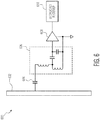
- FIG 4 is a third example mobile communications device 400.
- Broadcast signals 402 are transmitted by a broadcast transmitter (not shown).
- the bio-antenna 404 e.g. a user, a human body, an animal, a tree, a plant, etc., alive or not captures a portion of the broadcast signals 402, as shown in Figure 3 .
- a conducting surface 406 (forms a capacitor) is either affixed or placed proximately to the bio-antenna 404, thereby capacitively coupling the surface 406 with the bio-antenna 404.
- the conducting surface 406 conforms to a contour of the bio-antenna 404 to which it is attached.
- the conducting surface 406 is in one example embodiment a metalized plastic foil with a surface area of 2 by 3 cm 2 .
- the conducting surface 406 is attached to a portion of the bio-antenna 404 such as an arm. In other example embodiments, more than one conducting surface 406 can be attached and/or placed proximate to the bio-antenna 404.
- the conducting surface 406 is coupled to a filter 408.
- the filter 408 passes a set of broadcast band frequencies received by the conducting surface 406 to a broadcast receiver 410 (e.g. an FM radio receiver).
- the filter 408, in various example embodiments, can be tuned to a narrower portion of the broadcast band and/or perform additional impedance matching between the combination bio-antenna 404 and conducting surface 406 impedance and the broadcast receiver's 410 input impedance.
- the third example mobile communications device 400 couples the broadcast signals 402 to the broadcast receiver 410.
- FIG 5 is a first example electrical circuit 500 for the mobile communications device 400.
- a capacitive coupling 504 formed from the conducting surface 406 in Figure 4 , connects a bio-antenna 502 to a tuning circuit 506.
- the tuning circuit 506 includes an inductor and a capacitor, which in some example embodiments are adjustable.
- the tuning circuit 506 is coupled to a low noise amplifier 508. Together the tuning circuit 506 and the low noise amplifier 508 represent the filter 408 in Figure 4 .
- the low noise amplifier 508 is connected to a broadcast receiver 510 (e.g. radio system).
- the tuning circuit 506 and low noise amplifier 508 in one example are adjusted by the broadcast receiver 510.
- Figure 6 is a second example electrical circuit 600 for the mobile communications device 400.
- a capacitive coupling 604, formed from the conducting surface 406 in Figure 4 connects a bio-antenna 602 to a matching circuit 606.
- the matching circuit 606 includes multiple inductors and capacitors, which in some example embodiments are adjustable.
- the matching circuit 606 together with the bio-antenna 602 form a bandpass filter for a preselected portion of the broadcast frequency band.
- the formed bandpass filter covers the entire FM broadcast frequency band.
- the matching circuit 606 is coupled to a low noise amplifier 608. Together the matching circuit 606 and the low noise amplifier 608 represent the filter 408 in Figure 4 .
- the low noise amplifier 608 is connected to a broadcast receiver 610 (e.g. radio system).
- the matching circuit 606 and low noise amplifier 608 in one example are adjusted by the broadcast receiver 610.
- Figure 7 is a fourth example mobile communications device 700.
- the fourth example device 700 for broadcast reception is combined with a near field communication circuit and forms part of a body area network.
- the device's 700 broadcast reception functionality is integrated in a smart watch that is also able to use NFC to communicate with other wearable devices in the body area network.
- the demodulated broadcast radio audio or data can then use NFC to communicate this demodulated information to other NFC enabled devices.
- a conducting surface 704 forms a capacitive coupling between a bio-antenna 702 and a filter 706.
- the conductive surface 704 can be constructed from copper material attached to a flexible dielectric material.
- the thickness of the copper material can be for example 0.035 mm.
- the surface area of the conducting surface 704 in one example is about 3 cm x 2 cm.
- the filter 706 in one example is a tuning circuit and in another example is a matching circuit.
- the tuning circuit example includes an inductor and a capacitor, which in some example embodiments are adjustable.
- the matching circuit example includes multiple inductors and capacitors, which in some example embodiments are also adjustable.
- the filter 706 is coupled to a low noise amplifier 708.
- the low noise amplifier 708 is connected to a broadcast receiver 710 (e.g. radio system).
- the filter 706 and low noise amplifier 708 in one example are adjusted by the broadcast receiver 710.
- a coil 712 couples the conductive surface 704 to a near field communication (NFC) circuit 714.
- the coil 712 in one example can be a planar air coil having a 3.6 ⁇ Henry inductance.
- the coil 712 could be wound on a ferrite rod with a size of 2 mm diameter and 6 mm length.
- the coil 712 can be tuned to the NFC circuit's 714 operating frequency (e.g. 10.6 MHz) using a capacitor bank, resonance circuit and resistor bank integrated into the NFC circuit 714.
- the NFC circuit 714 may establish transmit and receive communications with one or more other NFC devices attached to the bio-antenna 702 or positioned nearby.
- NFC is known as a communications system which uses magnetic and/or electric induction.
- a portion of the NFC circuit's 714 electric near field may be generated and/or captured by the conductive surface 704.
- Broadcast reception can be in the FM frequency band from 88 to 108 MHz while the NFC circuit 714 can range between 8 and 15 MHz (10.6 MHz is a typical NFC operational frequency. Thus both the NFC and broadcast portions of the device 700 can operate concurrently.
- the filter 706 includes a blocking filter (not shown) at the NFC circuit's 714 frequencies of operation.
- the blocking filter can be a high-pass filter, low-pass filter or notch filter.
- the blocking filter reduces or prevents the NFC circuit 714 from injecting the NFC circuit's 714 transmit voltage signals into the low noise amplifier 708 used by the broadcast receiver 710.
- each of the elements described above, except the bio-antenna 702 are integrated into a single chip 716.
- the chip 716 may itself be embedded in a smartwatch (not shown) or other body wearable device or item (e.g. helmet, clothing, bandage, etc.).
- Figure 8 is a second example set of measurements 800 of a bio-antenna received signal strength 802 over a range of signal frequencies 804.
- the mobile communications device 400 includes the second example electrical circuit 600.
- the example set of measurements 800 displays multiple broadcast reception (i.e. FM transmitter) signals.
- the measurements were taken in an indoor setting, where signal levels are typically significantly attenuated as compared to an outdoor setting.
Landscapes
- Engineering & Computer Science (AREA)
- Signal Processing (AREA)
- Computer Networks & Wireless Communication (AREA)
- Near-Field Transmission Systems (AREA)
- Transceivers (AREA)
- Support Of Aerials (AREA)
- Measurement And Recording Of Electrical Phenomena And Electrical Characteristics Of The Living Body (AREA)
Abstract
Description
- The present specification relates to systems, methods, apparatuses, devices, articles of manufacture and instructions for communications.
- According to an example embodiment, a communications device, comprising: a bio-antenna conducting surface configured to receive a set of bio-antenna modulated broadcast signals; wherein the conducting surface is configured to receive the set of bio-antenna modulated broadcast signals through a capacitively coupling; a broadcast receiver coupled to the conducting surface; and wherein the conducting surface is configured to pass the broadcast signals to the broadcast receiver.
- In another example embodiment, the conducting surface is configured to be positioned proximate to but not directly touching a bio-antenna.
- In another example embodiment, the conducting surface conforms to a contour of a bio-antenna.
- In another example embodiment, the conductive surface has a set of planar dimensions that are less than 10% of a wavelength of the broadcast signals that the conductive surface is configured to receive.
- In another example embodiment, the conducting surface is configured to transmit and receive NFC signals and is configured to receive broadcast signals.
- In another example embodiment, the conducting surface includes at least one of: a metalized plastic foil; a copper material, or a flexible dielectric material.
- In another example embodiment, further comprising additional conducting surfaces configured to receive a second set of bio-antenna modulated broadcast signals and pass the second set of broadcast signals to the broadcast receiver.
- In another example embodiment, the set of broadcast signals are included in at least one of: an FM radio band; a set frequencies ranging from 87.5 MHz to 108.0 MHz; or a near field communications (NFC) frequency band.
- In another example embodiment, the bio-antenna conducting surface is configured to receive at least one of: a set of human body modulated broadcast signals, a set of human arm modulated broadcast signals, a set of biological structure modulated broadcast signals, a set of living organism modulated broadcast signals, a set of animal modulated broadcast signals, or a set of plant modulated broadcast signals.
- In another example embodiment, further comprising a filter coupled between the conducting surface and the broadcast receiver and configured to pass the set of broadcast band frequencies received by the conducting surface to the broadcast receiver.
- In another example embodiment, the filter is at least one of: a tuning circuit or a matching circuit.
- In another example embodiment, the broadcast receiver is an FM radio receiver.
- In another example embodiment, further comprising a coil and a near field communication (NFC) circuit; and the coil couples the NFC circuit to the conducting surface.
- In another example embodiment, the coil is at least one of: a planar air coil, or a wire wound on a ferrite rod.
- In another example embodiment, the coil is tuned to the NFC circuit's operating frequency.
- In another example embodiment, the NFC circuit is configured to be coupled to a set of nodes in a body area network; and the NFC circuit is configured to communicate with the set of nodes using near-field magnetic induction signals.
- In another example embodiment, further comprising a blocking filter coupled between the conducting surface and the broadcast receiver; and the blocking filter is configured to block a set of NFC circuit signals from reaching the broadcast receiver.
- In another example embodiment, the blocking filter is at least one of: a high-pass filter, low-pass filter, a notch filter, or a broadband bandpass filter.
- In another example embodiment, further comprising a first and second NFC device; wherein the communications device is configured to communicate a set of demodulated broadcast signals to the first NFC device; and wherein the first NFC device is configured to communicate the set of demodulated broadcast signals to the second NFC device.
- In another example embodiment, the communications device is embedded in at least one of: an earbud, a smartwatch; a medical implant; a smartphone, an item of clothing; a cellular phone, a portable radios, a wearable product, a body attached communication node, a chip, a semiconductor device, or a radio IC.
- In another example embodiment, the communications device is configured to receive at least one of: a magnetic induction signal; a near-field signal; a cellular signal, a Wi-Fi signal, a Bluetooth signal.
- The above discussion is not intended to represent every example embodiment or every implementation within the scope of the current or future Claim sets. The Figures and Detailed Description that follow also exemplify various example embodiments.
- Various example embodiments may be more completely understood in consideration of the following Detailed Description in connection with the accompanying Drawings, in which:
-
-
Figure 1 is a first example mobile communications device. -
Figure 2 is a second example mobile communications device. -
Figure 3 is a first example set of measurements. -
Figure 4 is a third example mobile communications device. -
Figure 5 is a first example electrical circuit for the mobile communications device. -
Figure 6 is a second example electrical circuit for the mobile communications device. -
Figure 7 is a fourth example mobile communications device. -
Figure 8 is a second example set of measurements. - While the disclosure is amenable to various modifications and alternative forms, specifics thereof have been shown by way of example in the drawings and will be described in detail. It should be understood, however, that other embodiments, beyond the particular embodiments described, are possible as well. All modifications, equivalents, and alternative embodiments falling within the spirit and scope of the appended claims are covered as well.
- Body wearable devices are a type of mobile device which can be either carried or worn by its user. Such devices may include: cellular phones, portable radios, wearable products, body attached communication nodes, and the like, perhaps designed to receive multiple communications bands at different frequencies, including: cellular, Wi-Fi, Bluetooth and broadcast.
- Some body wearable devices are able to communicate with each other as part of a body area network, where near fields are used to communicate between devices. Near field induction can operate in a frequency range between 8 and 30 MHz.
- The hardware necessary for these devices to receive communications varies.
-
Figure 1 is a one example ofmobile communications apparatus 100. The system includes acommunications device 102, a set of headset wires 104 (i.e. an antenna for receiving RF and baseband audio signals), and aheadset 106, wherein theheadset 106 is being worn by auser 108. - Broadcast reception is provided by the set of
headset wires 104, which functions as an antenna for an FM broadcast band (e.g. 87.5 to 108MHz). Theheadset wires 104 have a length greater than or equal to a quarter wave length of the broadcast reception frequency. - In this example, a cellular phone including the
mobile communications apparatus 100 would require attachment of a relative long wire to be able to receive the broadcast stations. In such an example if someone wants to listen to a FM station at 98 MHz then the shortest wire that can be considered has a quarter wave length (e.g. about 76 cm). In practice the antenna function can be combined with the headset wire which is roughly 90 cm long. Such an example requires the headset wire to be present for broadcast reception. -
Figure 2 is an examplemobile communications device 200. Thedevice 200 includes adisplay 202, abroadcast receiver 204, an integratedbroadcast antenna 206. - The
antenna 206 converts an electric field wirelessly received from of a broadcast transmitter (not shown) to an electric signal that can be further amplified and demodulated by thereceiver 204. Thereceiver 204 includes circuits for the reception of broadcast stations. - Since the
antenna 206 is integrated into thedevice 200, the antenna's 206 length is restricted and functions as a less efficient antenna then theheadset wires 104 of themobile communications apparatus 100. - While the antenna's 206 length is very short, compared with the wavelength, the
antenna 206 would still have a length on the order of 10 cm, which may still be rather longer than idea for some body worn device applications, such as a smartwatch. Also, due to the antenna's 206 shorter length the received broadcast signal strength is strongly attenuated. - For example a standard reference dipole antenna will receive 975 µVolts when it is placed at a location where the signal's field strength is 1 mV/meter (at a frequency of 98 MHz). However with the antenna length of 10 cm, the received signal will be only 50 µVolts when it is placed at a location where the field strength is 1 mV/meter (at a frequency of 98 MHz). This is a 25.8 dB signal level reduction.
-
Figure 3 is a first example set ofmeasurements 300 of a bio-antenna receivedsignal strength 302 over a range of signal frequencies. In the example set ofmeasurements 300 the data points are for a human body bio-antenna. Similar data points can be achieved when the bio-antenna is attached to various other biological structures. - The range of signal frequencies 304 (i.e. x-axis) presents a received frequency in logarithmic scale and the bio-antenna received signal strength 302 (i.e. y-axis) presents the relative strength in dB.
- These particular measurements were collected from a male person of 176 cm height. There is a resonance frequency at 60 MHz. The -10 dB bandwidth is found to be between 35 and 100 MHz. The resonance frequency can by a bit different between persons since it is dependent on height of the person. However it can be seen from this figure that efficient reception of broadcast signals is possible in the FM frequency band, wherein the human body acts as a bio-antenna.
-
Figure 4 is a third example mobile communications device 400. Broadcast signals 402 are transmitted by a broadcast transmitter (not shown). The bio-antenna 404 (e.g. a user, a human body, an animal, a tree, a plant, etc., alive or not) captures a portion of the broadcast signals 402, as shown inFigure 3 . - A conducting surface 406 (forms a capacitor) is either affixed or placed proximately to the bio-antenna 404, thereby capacitively coupling the
surface 406 with the bio-antenna 404. In certain example embodiments the conductingsurface 406 conforms to a contour of the bio-antenna 404 to which it is attached. The conductingsurface 406 is in one example embodiment a metalized plastic foil with a surface area of 2 by 3 cm2. - In one embodiment, the conducting
surface 406 is attached to a portion of the bio-antenna 404 such as an arm. In other example embodiments, more than one conductingsurface 406 can be attached and/or placed proximate to thebio-antenna 404. - The conducting
surface 406 is coupled to afilter 408. Thefilter 408 passes a set of broadcast band frequencies received by the conductingsurface 406 to a broadcast receiver 410 (e.g. an FM radio receiver). Thefilter 408, in various example embodiments, can be tuned to a narrower portion of the broadcast band and/or perform additional impedance matching between the combination bio-antenna 404 and conductingsurface 406 impedance and the broadcast receiver's 410 input impedance. - Thus the third example mobile communications device 400 couples the broadcast signals 402 to the
broadcast receiver 410. -
Figure 5 is a first exampleelectrical circuit 500 for the mobile communications device 400. Acapacitive coupling 504, formed from the conductingsurface 406 inFigure 4 , connects a bio-antenna 502 to atuning circuit 506. Thetuning circuit 506 includes an inductor and a capacitor, which in some example embodiments are adjustable. - The
tuning circuit 506 is coupled to alow noise amplifier 508. Together thetuning circuit 506 and thelow noise amplifier 508 represent thefilter 408 inFigure 4 . Thelow noise amplifier 508 is connected to a broadcast receiver 510 (e.g. radio system). Thetuning circuit 506 andlow noise amplifier 508 in one example are adjusted by thebroadcast receiver 510. -
Figure 6 is a second exampleelectrical circuit 600 for the mobile communications device 400. Acapacitive coupling 604, formed from the conductingsurface 406 inFigure 4 , connects a bio-antenna 602 to amatching circuit 606. - The
matching circuit 606 includes multiple inductors and capacitors, which in some example embodiments are adjustable. Thematching circuit 606 together with the bio-antenna 602 form a bandpass filter for a preselected portion of the broadcast frequency band. In another example embodiment the formed bandpass filter covers the entire FM broadcast frequency band. - The
matching circuit 606 is coupled to alow noise amplifier 608. Together thematching circuit 606 and thelow noise amplifier 608 represent thefilter 408 inFigure 4 . Thelow noise amplifier 608 is connected to a broadcast receiver 610 (e.g. radio system). Thematching circuit 606 andlow noise amplifier 608 in one example are adjusted by thebroadcast receiver 610. -
Figure 7 is a fourth examplemobile communications device 700. In this example embodiment, thefourth example device 700 for broadcast reception is combined with a near field communication circuit and forms part of a body area network. - In one example embodiment, the device's 700 broadcast reception functionality is integrated in a smart watch that is also able to use NFC to communicate with other wearable devices in the body area network. The demodulated broadcast radio audio or data can then use NFC to communicate this demodulated information to other NFC enabled devices.
- A conducting
surface 704 forms a capacitive coupling between a bio-antenna 702 and afilter 706. Theconductive surface 704 can be constructed from copper material attached to a flexible dielectric material. The thickness of the copper material can be for example 0.035 mm. The surface area of the conductingsurface 704 in one example is about 3 cm x 2 cm. - The
filter 706 in one example is a tuning circuit and in another example is a matching circuit. The tuning circuit example includes an inductor and a capacitor, which in some example embodiments are adjustable. The matching circuit example includes multiple inductors and capacitors, which in some example embodiments are also adjustable. - The
filter 706 is coupled to alow noise amplifier 708. Thelow noise amplifier 708 is connected to a broadcast receiver 710 (e.g. radio system). Thefilter 706 andlow noise amplifier 708 in one example are adjusted by thebroadcast receiver 710. - In this example, a
coil 712 couples theconductive surface 704 to a near field communication (NFC) circuit 714. Thecoil 712 in one example can be a planar air coil having a 3.6 µHenry inductance. Alternatively, thecoil 712 could be wound on a ferrite rod with a size of 2 mm diameter and 6 mm length. Thecoil 712 can be tuned to the NFC circuit's 714 operating frequency (e.g. 10.6 MHz) using a capacitor bank, resonance circuit and resistor bank integrated into the NFC circuit 714. - The NFC circuit 714 may establish transmit and receive communications with one or more other NFC devices attached to the bio-antenna 702 or positioned nearby. NFC is known as a communications system which uses magnetic and/or electric induction.
- If the NFC circuit 714 uses electric induction, a portion of the NFC circuit's 714 electric near field may be generated and/or captured by the
conductive surface 704. - Broadcast reception can be in the FM frequency band from 88 to 108 MHz while the NFC circuit 714 can range between 8 and 15 MHz (10.6 MHz is a typical NFC operational frequency. Thus both the NFC and broadcast portions of the
device 700 can operate concurrently. - However, to prevent interference between the mobile communications device's 700 broadcast reception functions and NFC transmit functions, the
filter 706 includes a blocking filter (not shown) at the NFC circuit's 714 frequencies of operation. The blocking filter can be a high-pass filter, low-pass filter or notch filter. - The blocking filter reduces or prevents the NFC circuit 714 from injecting the NFC circuit's 714 transmit voltage signals into the
low noise amplifier 708 used by thebroadcast receiver 710. - In one example embodiment, each of the elements described above, except the bio-antenna 702, are integrated into a
single chip 716. Thechip 716 may itself be embedded in a smartwatch (not shown) or other body wearable device or item (e.g. helmet, clothing, bandage, etc.). -
Figure 8 is a second example set of measurements 800 of a bio-antenna receivedsignal strength 802 over a range ofsignal frequencies 804. In this example 800 the mobile communications device 400 includes the second exampleelectrical circuit 600. - The example set of measurements 800 displays multiple broadcast reception (i.e. FM transmitter) signals. The measurements were taken in an indoor setting, where signal levels are typically significantly attenuated as compared to an outdoor setting.
- In this specification, example embodiments have been presented in terms of a selected set of details. However, a person of ordinary skill in the art would understand that many other example embodiments may be practiced which include a different selected set of these details. It is intended that the following claims cover all possible example embodiments.
Claims (15)
- A communications device, comprising:a bio-antenna conducting surface configured to receive a set of bio-antenna modulated broadcast signals;wherein the conducting surface is configured to receive the set of bio-antenna modulated broadcast signals through a capacitively coupling;a broadcast receiver coupled to the conducting surface; andwherein the conducting surface is configured to pass the broadcast signals to the broadcast receiver.
- The device of claim 1:wherein the conducting surface is configured to be positioned proximate to but not directly touching a bio-antenna.
- The device of claim 1 or 2:wherein the conducting surface conforms to a contour of a bio-antenna.
- The device of any preceding claim:wherein the conductive surface has a set of planar dimensions that are less than 10% of a wavelength of the broadcast signals that the conductive surface is configured to receive.
- The device of any preceding claim:wherein the conducting surface is configured to transmit and receive NFC signals and is configured to receive broadcast signals.
- The device of any preceding claim:wherein the conducting surface includes at least one of: a metalized plastic foil; a copper material, or a flexible dielectric material.
- The device of any preceding claim:further comprising additional conducting surfaces configured to receive a second set of bio-antenna modulated broadcast signals and pass the second set of broadcast signals to the broadcast receiver.
- The device of any preceding claim:wherein the set of broadcast signals are included in at least one of: an FM radio band; a set frequencies ranging from 87.5 MHz to 108.0 MHz; or a near field communications (NFC) frequency band.
- The device of any preceding claim:wherein the bio-antenna conducting surface is configured to receive at least one of: a set of human body modulated broadcast signals, a set of human arm modulated broadcast signals, a set of biological structure modulated broadcast signals, a set of living organism modulated broadcast signals, a set of animal modulated broadcast signals, or a set of plant modulated broadcast signals.
- The device of any preceding claim:further comprising a filter coupled between the conducting surface and the broadcast receiver and configured to pass the set of broadcast band frequencies received by the conducting surface to the broadcast receiver.
- The device of claim 10:wherein the filter is at least one of: a tuning circuit or a matching circuit.
- The device of any preceding claim:wherein the broadcast receiver is an FM radio receiver.
- The device of any preceding claim:further comprising a coil and a near field communication (NFC) circuit; andwherein the coil couples the NFC circuit to the conducting surface.
- The device of claim 13:wherein the coil is at least one of: a planar air coil, or a wire wound on a ferrite rod.
- The device of claim 13 or 14:wherein the coil is tuned to the NFC circuit's operating frequency.
Applications Claiming Priority (1)
| Application Number | Priority Date | Filing Date | Title |
|---|---|---|---|
| US15/090,933 US9906272B2 (en) | 2016-04-05 | 2016-04-05 | Communications device |
Publications (2)
| Publication Number | Publication Date |
|---|---|
| EP3229317A1 true EP3229317A1 (en) | 2017-10-11 |
| EP3229317B1 EP3229317B1 (en) | 2020-06-17 |
Family
ID=58448485
Family Applications (1)
| Application Number | Title | Priority Date | Filing Date |
|---|---|---|---|
| EP17163409.0A Active EP3229317B1 (en) | 2016-04-05 | 2017-03-28 | Communications device with conductive surface coupled to human body |
Country Status (3)
| Country | Link |
|---|---|
| US (1) | US9906272B2 (en) |
| EP (1) | EP3229317B1 (en) |
| CN (1) | CN107276636B (en) |
Families Citing this family (9)
| Publication number | Priority date | Publication date | Assignee | Title |
|---|---|---|---|---|
| CN207052767U (en) * | 2017-05-12 | 2018-02-27 | 中兴通讯股份有限公司 | Antenna circuit, coupling module and Wireless Telecom Equipment for antenna conversion |
| CN108199798B (en) * | 2017-12-11 | 2020-08-18 | 科大讯飞股份有限公司 | A power supply circuit for a radio antenna |
| US20190265473A1 (en) * | 2018-02-23 | 2019-08-29 | Oculus Vr, Llc | Apparatus, systems, and methods for enabling low-power communications via wearers' bodies |
| US11031680B2 (en) | 2018-10-02 | 2021-06-08 | Nxp B.V. | Near-field electromagnetic induction (NFEMI) antenna |
| US10498397B1 (en) * | 2019-05-07 | 2019-12-03 | Nxp B.V. | Wireless device |
| US11211694B2 (en) * | 2019-07-08 | 2021-12-28 | Nxp B.V. | Near-field wireless device |
| JP7793302B2 (en) * | 2021-06-17 | 2026-01-05 | キヤノン株式会社 | COMMUNICATION DEVICE, COMMUNICATION SYSTEM, AND METHOD FOR CONTROLLING COMMUNICATION DEVICE |
| US11594369B1 (en) | 2021-11-18 | 2023-02-28 | Finnovate Group LLC | Magnetic field audio loop for swimming pools |
| JP7794702B2 (en) * | 2022-06-30 | 2026-01-06 | 京セラ株式会社 | electronic equipment |
Citations (2)
| Publication number | Priority date | Publication date | Assignee | Title |
|---|---|---|---|---|
| US20020030630A1 (en) * | 2000-09-11 | 2002-03-14 | Noboru Maeda | Antenna for portable radio communication device and method of transmitting radio signal |
| US20100019982A1 (en) * | 2008-07-24 | 2010-01-28 | Sony Corporation | Communication apparatus |
Family Cites Families (14)
| Publication number | Priority date | Publication date | Assignee | Title |
|---|---|---|---|---|
| JP4114143B2 (en) * | 2003-02-27 | 2008-07-09 | ソニー株式会社 | COMMUNICATION SYSTEM, COMMUNICATION METHOD, AND COMMUNICATION DEVICE |
| US8121662B2 (en) | 2006-07-28 | 2012-02-21 | Marvell World Trade Ltd. | Virtual FM antenna |
| CA2576615C (en) * | 2007-02-01 | 2012-01-03 | Emma Mixed Signal C.V. | Body radiation and conductivity in rf communication |
| US8634773B2 (en) * | 2007-10-12 | 2014-01-21 | Cochlear Limited | Short range communications for body contacting devices |
| US9054773B2 (en) | 2008-03-21 | 2015-06-09 | Nxp B.V. | Apparatus comprising a broadcast receiver circuit and provided with an antenna |
| US9659423B2 (en) * | 2008-12-15 | 2017-05-23 | Proteus Digital Health, Inc. | Personal authentication apparatus system and method |
| EP2393215B1 (en) | 2010-06-03 | 2015-10-21 | Nxp B.V. | Radio receiver and transmitter circuits, and corresponding methods |
| US8350695B2 (en) * | 2010-06-24 | 2013-01-08 | Lojack Operating Company, Lp | Body coupled antenna system and personal locator unit utilizing same |
| WO2014030317A1 (en) * | 2012-08-24 | 2014-02-27 | パナソニックヘルスケア株式会社 | Human body communication device and communication apparatus |
| FR3004563A1 (en) * | 2013-04-15 | 2014-10-17 | Inside Secure | METHOD OF ACQUIRING BIOLOGICAL INFORMATION USING AN INTRA-CURRENT CURRENT |
| CN104577357B (en) * | 2013-10-17 | 2019-03-12 | 中兴通讯股份有限公司 | An antenna and mobile terminal |
| US9351100B2 (en) * | 2013-12-05 | 2016-05-24 | Sony Corporation | Device for control of data transfer in local area network |
| US9197986B1 (en) | 2014-06-12 | 2015-11-24 | Nxp, B.V. | Electromagnetic induction radio |
| US9667354B2 (en) * | 2014-11-24 | 2017-05-30 | Sony Corporation | Situational based communication |
-
2016
- 2016-04-05 US US15/090,933 patent/US9906272B2/en active Active
-
2017
- 2017-03-21 CN CN201710171678.XA patent/CN107276636B/en active Active
- 2017-03-28 EP EP17163409.0A patent/EP3229317B1/en active Active
Patent Citations (2)
| Publication number | Priority date | Publication date | Assignee | Title |
|---|---|---|---|---|
| US20020030630A1 (en) * | 2000-09-11 | 2002-03-14 | Noboru Maeda | Antenna for portable radio communication device and method of transmitting radio signal |
| US20100019982A1 (en) * | 2008-07-24 | 2010-01-28 | Sony Corporation | Communication apparatus |
Also Published As
| Publication number | Publication date |
|---|---|
| CN107276636B (en) | 2022-01-11 |
| US20170288731A1 (en) | 2017-10-05 |
| CN107276636A (en) | 2017-10-20 |
| US9906272B2 (en) | 2018-02-27 |
| EP3229317B1 (en) | 2020-06-17 |
Similar Documents
| Publication | Publication Date | Title |
|---|---|---|
| EP3229317B1 (en) | Communications device with conductive surface coupled to human body | |
| CN106486778B (en) | Antenna system | |
| US9819395B2 (en) | Apparatus and method for wireless body communication | |
| TWI451627B (en) | Virtual fm antenna | |
| US9819075B2 (en) | Body communication antenna | |
| US20050099341A1 (en) | Antenna for a wireless hearing aid system | |
| US8724835B2 (en) | Radio receiver, radio transmitter, and hearing aid | |
| US10014578B2 (en) | Body antenna system | |
| US11038257B2 (en) | Antenna structure and communications terminal | |
| US11011826B2 (en) | Near-field electromagnetic induction (NFEMI) device | |
| WO2019114622A1 (en) | Antenna tuning circuit, antena apparatus and mobile terminal | |
| CN108695593B (en) | Near Field Electromagnetic Induction (NFEMI) Antennas | |
| EP3917022A1 (en) | Near-field wireless device | |
| US10978791B2 (en) | Combination antenna | |
| CN111490811B (en) | near field communication device | |
| JP2003508944A (en) | Long personal communication device | |
| US7411559B2 (en) | Headset loop antenna | |
| CN106981361B (en) | Electromagnetic device | |
| CN204967801U (en) | Antenna circuitry and mobile terminal | |
| CN115152153B (en) | Near Field Communication | |
| EP1689021A1 (en) | In-built FM antenna |
Legal Events
| Date | Code | Title | Description |
|---|---|---|---|
| PUAI | Public reference made under article 153(3) epc to a published international application that has entered the european phase |
Free format text: ORIGINAL CODE: 0009012 |
|
| STAA | Information on the status of an ep patent application or granted ep patent |
Free format text: STATUS: THE APPLICATION HAS BEEN PUBLISHED |
|
| AK | Designated contracting states |
Kind code of ref document: A1 Designated state(s): AL AT BE BG CH CY CZ DE DK EE ES FI FR GB GR HR HU IE IS IT LI LT LU LV MC MK MT NL NO PL PT RO RS SE SI SK SM TR |
|
| AX | Request for extension of the european patent |
Extension state: BA ME |
|
| STAA | Information on the status of an ep patent application or granted ep patent |
Free format text: STATUS: REQUEST FOR EXAMINATION WAS MADE |
|
| 17P | Request for examination filed |
Effective date: 20180411 |
|
| RBV | Designated contracting states (corrected) |
Designated state(s): AL AT BE BG CH CY CZ DE DK EE ES FI FR GB GR HR HU IE IS IT LI LT LU LV MC MK MT NL NO PL PT RO RS SE SI SK SM TR |
|
| GRAP | Despatch of communication of intention to grant a patent |
Free format text: ORIGINAL CODE: EPIDOSNIGR1 |
|
| STAA | Information on the status of an ep patent application or granted ep patent |
Free format text: STATUS: GRANT OF PATENT IS INTENDED |
|
| INTG | Intention to grant announced |
Effective date: 20200120 |
|
| GRAS | Grant fee paid |
Free format text: ORIGINAL CODE: EPIDOSNIGR3 |
|
| GRAA | (expected) grant |
Free format text: ORIGINAL CODE: 0009210 |
|
| STAA | Information on the status of an ep patent application or granted ep patent |
Free format text: STATUS: THE PATENT HAS BEEN GRANTED |
|
| AK | Designated contracting states |
Kind code of ref document: B1 Designated state(s): AL AT BE BG CH CY CZ DE DK EE ES FI FR GB GR HR HU IE IS IT LI LT LU LV MC MK MT NL NO PL PT RO RS SE SI SK SM TR |
|
| REG | Reference to a national code |
Ref country code: GB Ref legal event code: FG4D |
|
| REG | Reference to a national code |
Ref country code: CH Ref legal event code: EP |
|
| REG | Reference to a national code |
Ref country code: IE Ref legal event code: FG4D |
|
| REG | Reference to a national code |
Ref country code: DE Ref legal event code: R096 Ref document number: 602017018145 Country of ref document: DE |
|
| REG | Reference to a national code |
Ref country code: AT Ref legal event code: REF Ref document number: 1282463 Country of ref document: AT Kind code of ref document: T Effective date: 20200715 |
|
| PG25 | Lapsed in a contracting state [announced via postgrant information from national office to epo] |
Ref country code: FI Free format text: LAPSE BECAUSE OF FAILURE TO SUBMIT A TRANSLATION OF THE DESCRIPTION OR TO PAY THE FEE WITHIN THE PRESCRIBED TIME-LIMIT Effective date: 20200617 Ref country code: GR Free format text: LAPSE BECAUSE OF FAILURE TO SUBMIT A TRANSLATION OF THE DESCRIPTION OR TO PAY THE FEE WITHIN THE PRESCRIBED TIME-LIMIT Effective date: 20200918 Ref country code: NO Free format text: LAPSE BECAUSE OF FAILURE TO SUBMIT A TRANSLATION OF THE DESCRIPTION OR TO PAY THE FEE WITHIN THE PRESCRIBED TIME-LIMIT Effective date: 20200917 Ref country code: LT Free format text: LAPSE BECAUSE OF FAILURE TO SUBMIT A TRANSLATION OF THE DESCRIPTION OR TO PAY THE FEE WITHIN THE PRESCRIBED TIME-LIMIT Effective date: 20200617 Ref country code: SE Free format text: LAPSE BECAUSE OF FAILURE TO SUBMIT A TRANSLATION OF THE DESCRIPTION OR TO PAY THE FEE WITHIN THE PRESCRIBED TIME-LIMIT Effective date: 20200617 |
|
| REG | Reference to a national code |
Ref country code: LT Ref legal event code: MG4D |
|
| REG | Reference to a national code |
Ref country code: NL Ref legal event code: MP Effective date: 20200617 |
|
| PG25 | Lapsed in a contracting state [announced via postgrant information from national office to epo] |
Ref country code: BG Free format text: LAPSE BECAUSE OF FAILURE TO SUBMIT A TRANSLATION OF THE DESCRIPTION OR TO PAY THE FEE WITHIN THE PRESCRIBED TIME-LIMIT Effective date: 20200917 Ref country code: HR Free format text: LAPSE BECAUSE OF FAILURE TO SUBMIT A TRANSLATION OF THE DESCRIPTION OR TO PAY THE FEE WITHIN THE PRESCRIBED TIME-LIMIT Effective date: 20200617 Ref country code: LV Free format text: LAPSE BECAUSE OF FAILURE TO SUBMIT A TRANSLATION OF THE DESCRIPTION OR TO PAY THE FEE WITHIN THE PRESCRIBED TIME-LIMIT Effective date: 20200617 Ref country code: RS Free format text: LAPSE BECAUSE OF FAILURE TO SUBMIT A TRANSLATION OF THE DESCRIPTION OR TO PAY THE FEE WITHIN THE PRESCRIBED TIME-LIMIT Effective date: 20200617 |
|
| REG | Reference to a national code |
Ref country code: AT Ref legal event code: MK05 Ref document number: 1282463 Country of ref document: AT Kind code of ref document: T Effective date: 20200617 |
|
| PG25 | Lapsed in a contracting state [announced via postgrant information from national office to epo] |
Ref country code: AL Free format text: LAPSE BECAUSE OF FAILURE TO SUBMIT A TRANSLATION OF THE DESCRIPTION OR TO PAY THE FEE WITHIN THE PRESCRIBED TIME-LIMIT Effective date: 20200617 Ref country code: NL Free format text: LAPSE BECAUSE OF FAILURE TO SUBMIT A TRANSLATION OF THE DESCRIPTION OR TO PAY THE FEE WITHIN THE PRESCRIBED TIME-LIMIT Effective date: 20200617 |
|
| PG25 | Lapsed in a contracting state [announced via postgrant information from national office to epo] |
Ref country code: ES Free format text: LAPSE BECAUSE OF FAILURE TO SUBMIT A TRANSLATION OF THE DESCRIPTION OR TO PAY THE FEE WITHIN THE PRESCRIBED TIME-LIMIT Effective date: 20200617 Ref country code: PT Free format text: LAPSE BECAUSE OF FAILURE TO SUBMIT A TRANSLATION OF THE DESCRIPTION OR TO PAY THE FEE WITHIN THE PRESCRIBED TIME-LIMIT Effective date: 20201019 Ref country code: IT Free format text: LAPSE BECAUSE OF FAILURE TO SUBMIT A TRANSLATION OF THE DESCRIPTION OR TO PAY THE FEE WITHIN THE PRESCRIBED TIME-LIMIT Effective date: 20200617 Ref country code: RO Free format text: LAPSE BECAUSE OF FAILURE TO SUBMIT A TRANSLATION OF THE DESCRIPTION OR TO PAY THE FEE WITHIN THE PRESCRIBED TIME-LIMIT Effective date: 20200617 Ref country code: CZ Free format text: LAPSE BECAUSE OF FAILURE TO SUBMIT A TRANSLATION OF THE DESCRIPTION OR TO PAY THE FEE WITHIN THE PRESCRIBED TIME-LIMIT Effective date: 20200617 Ref country code: AT Free format text: LAPSE BECAUSE OF FAILURE TO SUBMIT A TRANSLATION OF THE DESCRIPTION OR TO PAY THE FEE WITHIN THE PRESCRIBED TIME-LIMIT Effective date: 20200617 Ref country code: SM Free format text: LAPSE BECAUSE OF FAILURE TO SUBMIT A TRANSLATION OF THE DESCRIPTION OR TO PAY THE FEE WITHIN THE PRESCRIBED TIME-LIMIT Effective date: 20200617 Ref country code: EE Free format text: LAPSE BECAUSE OF FAILURE TO SUBMIT A TRANSLATION OF THE DESCRIPTION OR TO PAY THE FEE WITHIN THE PRESCRIBED TIME-LIMIT Effective date: 20200617 |
|
| PG25 | Lapsed in a contracting state [announced via postgrant information from national office to epo] |
Ref country code: PL Free format text: LAPSE BECAUSE OF FAILURE TO SUBMIT A TRANSLATION OF THE DESCRIPTION OR TO PAY THE FEE WITHIN THE PRESCRIBED TIME-LIMIT Effective date: 20200617 Ref country code: SK Free format text: LAPSE BECAUSE OF FAILURE TO SUBMIT A TRANSLATION OF THE DESCRIPTION OR TO PAY THE FEE WITHIN THE PRESCRIBED TIME-LIMIT Effective date: 20200617 Ref country code: IS Free format text: LAPSE BECAUSE OF FAILURE TO SUBMIT A TRANSLATION OF THE DESCRIPTION OR TO PAY THE FEE WITHIN THE PRESCRIBED TIME-LIMIT Effective date: 20201017 |
|
| REG | Reference to a national code |
Ref country code: DE Ref legal event code: R097 Ref document number: 602017018145 Country of ref document: DE |
|
| PLBE | No opposition filed within time limit |
Free format text: ORIGINAL CODE: 0009261 |
|
| STAA | Information on the status of an ep patent application or granted ep patent |
Free format text: STATUS: NO OPPOSITION FILED WITHIN TIME LIMIT |
|
| PG25 | Lapsed in a contracting state [announced via postgrant information from national office to epo] |
Ref country code: DK Free format text: LAPSE BECAUSE OF FAILURE TO SUBMIT A TRANSLATION OF THE DESCRIPTION OR TO PAY THE FEE WITHIN THE PRESCRIBED TIME-LIMIT Effective date: 20200617 |
|
| 26N | No opposition filed |
Effective date: 20210318 |
|
| PG25 | Lapsed in a contracting state [announced via postgrant information from national office to epo] |
Ref country code: SI Free format text: LAPSE BECAUSE OF FAILURE TO SUBMIT A TRANSLATION OF THE DESCRIPTION OR TO PAY THE FEE WITHIN THE PRESCRIBED TIME-LIMIT Effective date: 20200617 |
|
| PG25 | Lapsed in a contracting state [announced via postgrant information from national office to epo] |
Ref country code: MC Free format text: LAPSE BECAUSE OF FAILURE TO SUBMIT A TRANSLATION OF THE DESCRIPTION OR TO PAY THE FEE WITHIN THE PRESCRIBED TIME-LIMIT Effective date: 20200617 |
|
| REG | Reference to a national code |
Ref country code: CH Ref legal event code: PL |
|
| GBPC | Gb: european patent ceased through non-payment of renewal fee |
Effective date: 20210328 |
|
| REG | Reference to a national code |
Ref country code: BE Ref legal event code: MM Effective date: 20210331 |
|
| PG25 | Lapsed in a contracting state [announced via postgrant information from national office to epo] |
Ref country code: GB Free format text: LAPSE BECAUSE OF NON-PAYMENT OF DUE FEES Effective date: 20210328 Ref country code: FR Free format text: LAPSE BECAUSE OF NON-PAYMENT OF DUE FEES Effective date: 20210331 Ref country code: IE Free format text: LAPSE BECAUSE OF NON-PAYMENT OF DUE FEES Effective date: 20210328 Ref country code: CH Free format text: LAPSE BECAUSE OF NON-PAYMENT OF DUE FEES Effective date: 20210331 Ref country code: LU Free format text: LAPSE BECAUSE OF NON-PAYMENT OF DUE FEES Effective date: 20210328 Ref country code: LI Free format text: LAPSE BECAUSE OF NON-PAYMENT OF DUE FEES Effective date: 20210331 |
|
| PG25 | Lapsed in a contracting state [announced via postgrant information from national office to epo] |
Ref country code: BE Free format text: LAPSE BECAUSE OF NON-PAYMENT OF DUE FEES Effective date: 20210331 |
|
| PG25 | Lapsed in a contracting state [announced via postgrant information from national office to epo] |
Ref country code: HU Free format text: LAPSE BECAUSE OF FAILURE TO SUBMIT A TRANSLATION OF THE DESCRIPTION OR TO PAY THE FEE WITHIN THE PRESCRIBED TIME-LIMIT; INVALID AB INITIO Effective date: 20170328 |
|
| PG25 | Lapsed in a contracting state [announced via postgrant information from national office to epo] |
Ref country code: CY Free format text: LAPSE BECAUSE OF FAILURE TO SUBMIT A TRANSLATION OF THE DESCRIPTION OR TO PAY THE FEE WITHIN THE PRESCRIBED TIME-LIMIT Effective date: 20200617 |
|
| P01 | Opt-out of the competence of the unified patent court (upc) registered |
Effective date: 20230725 |
|
| PG25 | Lapsed in a contracting state [announced via postgrant information from national office to epo] |
Ref country code: MK Free format text: LAPSE BECAUSE OF FAILURE TO SUBMIT A TRANSLATION OF THE DESCRIPTION OR TO PAY THE FEE WITHIN THE PRESCRIBED TIME-LIMIT Effective date: 20200617 |
|
| PG25 | Lapsed in a contracting state [announced via postgrant information from national office to epo] |
Ref country code: TR Free format text: LAPSE BECAUSE OF FAILURE TO SUBMIT A TRANSLATION OF THE DESCRIPTION OR TO PAY THE FEE WITHIN THE PRESCRIBED TIME-LIMIT Effective date: 20200617 |
|
| PG25 | Lapsed in a contracting state [announced via postgrant information from national office to epo] |
Ref country code: MT Free format text: LAPSE BECAUSE OF FAILURE TO SUBMIT A TRANSLATION OF THE DESCRIPTION OR TO PAY THE FEE WITHIN THE PRESCRIBED TIME-LIMIT Effective date: 20200617 |
|
| PGFP | Annual fee paid to national office [announced via postgrant information from national office to epo] |
Ref country code: DE Payment date: 20260219 Year of fee payment: 10 |