EP3229246A1 - Oil type phase shift transformer for medium voltage inverter system - Google Patents
Oil type phase shift transformer for medium voltage inverter system Download PDFInfo
- Publication number
- EP3229246A1 EP3229246A1 EP16201174.6A EP16201174A EP3229246A1 EP 3229246 A1 EP3229246 A1 EP 3229246A1 EP 16201174 A EP16201174 A EP 16201174A EP 3229246 A1 EP3229246 A1 EP 3229246A1
- Authority
- EP
- European Patent Office
- Prior art keywords
- phase shift
- tank
- transformer
- voltage
- winding
- Prior art date
- Legal status (The legal status is an assumption and is not a legal conclusion. Google has not performed a legal analysis and makes no representation as to the accuracy of the status listed.)
- Granted
Links
Images




Classifications
-
- H—ELECTRICITY
- H01—ELECTRIC ELEMENTS
- H01F—MAGNETS; INDUCTANCES; TRANSFORMERS; SELECTION OF MATERIALS FOR THEIR MAGNETIC PROPERTIES
- H01F38/00—Adaptations of transformers or inductances for specific applications or functions
-
- H—ELECTRICITY
- H01—ELECTRIC ELEMENTS
- H01F—MAGNETS; INDUCTANCES; TRANSFORMERS; SELECTION OF MATERIALS FOR THEIR MAGNETIC PROPERTIES
- H01F27/00—Details of transformers or inductances, in general
- H01F27/02—Casings
- H01F27/04—Leading of conductors or axles through casings, e.g. for tap-changing arrangements
-
- H—ELECTRICITY
- H01—ELECTRIC ELEMENTS
- H01F—MAGNETS; INDUCTANCES; TRANSFORMERS; SELECTION OF MATERIALS FOR THEIR MAGNETIC PROPERTIES
- H01F27/00—Details of transformers or inductances, in general
- H01F27/08—Cooling; Ventilating
- H01F27/10—Liquid cooling
- H01F27/12—Oil cooling
-
- H—ELECTRICITY
- H01—ELECTRIC ELEMENTS
- H01F—MAGNETS; INDUCTANCES; TRANSFORMERS; SELECTION OF MATERIALS FOR THEIR MAGNETIC PROPERTIES
- H01F27/00—Details of transformers or inductances, in general
- H01F27/02—Casings
-
- H—ELECTRICITY
- H01—ELECTRIC ELEMENTS
- H01F—MAGNETS; INDUCTANCES; TRANSFORMERS; SELECTION OF MATERIALS FOR THEIR MAGNETIC PROPERTIES
- H01F27/00—Details of transformers or inductances, in general
- H01F27/08—Cooling; Ventilating
- H01F27/22—Cooling by heat conduction through solid or powdered fillings
-
- H—ELECTRICITY
- H01—ELECTRIC ELEMENTS
- H01F—MAGNETS; INDUCTANCES; TRANSFORMERS; SELECTION OF MATERIALS FOR THEIR MAGNETIC PROPERTIES
- H01F27/00—Details of transformers or inductances, in general
- H01F27/28—Coils; Windings; Conductive connections
- H01F27/2876—Cooling
-
- H—ELECTRICITY
- H01—ELECTRIC ELEMENTS
- H01F—MAGNETS; INDUCTANCES; TRANSFORMERS; SELECTION OF MATERIALS FOR THEIR MAGNETIC PROPERTIES
- H01F27/00—Details of transformers or inductances, in general
- H01F27/28—Coils; Windings; Conductive connections
- H01F27/29—Terminals; Tapping arrangements for signal inductances
-
- H—ELECTRICITY
- H01—ELECTRIC ELEMENTS
- H01F—MAGNETS; INDUCTANCES; TRANSFORMERS; SELECTION OF MATERIALS FOR THEIR MAGNETIC PROPERTIES
- H01F29/00—Variable transformers or inductances not covered by group H01F21/00
- H01F29/02—Variable transformers or inductances not covered by group H01F21/00 with tappings on coil or winding; with provision for rearrangement or interconnection of windings
-
- H—ELECTRICITY
- H01—ELECTRIC ELEMENTS
- H01F—MAGNETS; INDUCTANCES; TRANSFORMERS; SELECTION OF MATERIALS FOR THEIR MAGNETIC PROPERTIES
- H01F29/00—Variable transformers or inductances not covered by group H01F21/00
- H01F29/02—Variable transformers or inductances not covered by group H01F21/00 with tappings on coil or winding; with provision for rearrangement or interconnection of windings
- H01F29/04—Variable transformers or inductances not covered by group H01F21/00 with tappings on coil or winding; with provision for rearrangement or interconnection of windings having provision for tap-changing without interrupting the load current
-
- H—ELECTRICITY
- H01—ELECTRIC ELEMENTS
- H01H—ELECTRIC SWITCHES; RELAYS; SELECTORS; EMERGENCY PROTECTIVE DEVICES
- H01H9/00—Details of switching devices, not covered by groups H01H1/00 - H01H7/00
- H01H9/0005—Tap change devices
- H01H9/0044—Casings; Mountings; Disposition in transformer housing
-
- H—ELECTRICITY
- H02—GENERATION; CONVERSION OR DISTRIBUTION OF ELECTRIC POWER
- H02M—APPARATUS FOR CONVERSION BETWEEN AC AND AC, BETWEEN AC AND DC, OR BETWEEN DC AND DC, AND FOR USE WITH MAINS OR SIMILAR POWER SUPPLY SYSTEMS; CONVERSION OF DC OR AC INPUT POWER INTO SURGE OUTPUT POWER; CONTROL OR REGULATION THEREOF
- H02M7/00—Conversion of AC power input into DC power output; Conversion of DC power input into AC power output
- H02M7/42—Conversion of DC power input into AC power output without possibility of reversal
- H02M7/44—Conversion of DC power input into AC power output without possibility of reversal by static converters
-
- H—ELECTRICITY
- H01—ELECTRIC ELEMENTS
- H01H—ELECTRIC SWITCHES; RELAYS; SELECTORS; EMERGENCY PROTECTIVE DEVICES
- H01H9/00—Details of switching devices, not covered by groups H01H1/00 - H01H7/00
- H01H9/0005—Tap change devices
- H01H9/0044—Casings; Mountings; Disposition in transformer housing
- H01H2009/005—Details concerning the sealing of the oil filled casings
Definitions
- the present invention relates to an oil type phase shift transformer for a medium voltage inverter system.
- a voltage type medium voltage inverter is an inverter whose root mean square value of input line-to-line voltage is 600V or more, which is used to drive an electric motor having large capacity of several hundreds of kW to several tens of MW.
- Such medium voltage inverter is typically configured as a cascaded H-bridge type.
- This medium voltage inverter requires a phase shift transformer in order to provide galvanic isolation and harmonics mitigation to an input terminal and supply input power to each of unit power cells.
- This phase shift transformer is a very important factor in design of the medium voltage inverter because it occupies the majority of volume and weight of the medium voltage inverter.
- phase shift transformer is divided into an oil type transformer and a dry type transformer depending on use of insulating oil.
- the dry type transformer has been used.
- an identification code for protection is IP20, which is not suitable to be installed outdoors.
- the first digit in the IP rating indicates a vibration proof level and the second digit indicates a water proof level.
- the transformer it is almost impossible to protect the transformer from dust, in particular water.
- the dry type phase shift transformer must be installed indoors in the same way as the unit power cell.
- Fig. 1 is a configuration diagram of a conventional medium voltage inverter system.
- phase shift transformer 200 is contained in a separate panel and disposed by the side of a panel containing power cells 100.
- a forced cooling fan for maintaining temperature of the transformer is required to be installed on the top of the panel.
- phase shift transformer for a medium voltage inverter system, which is configured as an oil type phase shift transformer so that spatial degrees of freedom are secured and high voltage devices and low voltage devices are managed separately.
- a phase shift transformer for supplying voltage to a plurality of unit power cells in a medium voltage inverter system comprises: a first winding which is configured to surround the outside of a core and to which three phase high voltage is applied; a plurality of second windings which are configured to surround the outside of the core and convert high voltage applied thereto from the first winding to low voltage; a tank providing an internal space in which the core, the first winding and the plurality of second windings are arranged and containing insulating oil therein; a cover provided on the top of the tank to provide a sealed internal space along with the tank; a first bushing arranged by the side of the tank and connected to the first winding to apply high voltage; and a plurality of second bushings arranged on the top of the cover and connected to each of the plurality of second windings to output low voltage, wherein three outputs of the plurality of second bushings can be applied to the unit power cells.
- the phase shift transformer may further comprise radiators arranged on the front and back surfaces of the tank to cool the insulating oil or the first winding and the second windings.
- the phase shift transformer may further comprise a tap changer arranged on the top of the cover to control voltage variation during operation of the phase shift transformer.
- the phase shift transformer may further comprise a housing in which the plurality of low voltage bushings are arranged, wherein the housing can be provided such that a top cover is capable of being opened and closed.
- the transformer can be installed outdoors and hence it is possible to minimize indoor area for installing the transformer by installing only the unit power cells indoors. Therefore, there are advantageous effects that spatial degrees of freedom in the design of the medium voltage inverter system are increased and that it is possible to manage separately high voltage devices and low voltage devices.
- Fig. 2 is a configuration diagram illustrating schematically a multi-level medium voltage inverter system to which the present invention is applied.
- the medium voltage inverter system to which the present invention is applied comprises an oil type phase shift transformer 1 and a plurality of unit power cells 2 according to an embodiment of the present invention.
- the resulting voltage output from the plurality of unit power cells 2 can be output to a three phase electric motor 3.
- the phase shift transformer 1, of which primary side input is about 3 to 11kV and secondary side output is about 635V, may be composed of a plurality of coils.
- a plurality of unit power cells 2 may stack secondary side voltages to make up a variable output to apply to an electric motor.
- Fig. 3 is an exemplary representation illustrating the medium voltage inverter system which is implemented indoors in accordance with the present invention.
- phase shift transformer 1 is configured as an oil type phase shift transformer, there is no need for the phase shift transformer to be installed indoors and thus, it is possible to place only a panel containing the plurality of unit power cells 2 indoors. Therefore, it can be seen that spatial degrees of freedom are increased because of no requirement for the space where the phase shift transformer 1 has been placed.
- Fig. 4 is an exemplary representation illustrating windings and a core which are implemented in the interior of an oil type transformer according to the present invention.
- windings 13 and 15 are configured to surround the outside of a core 10, wherein the windings include a primary winding 13 (hereinafter, referred to as "first winding") and a secondary winding 15 (hereinafter, referred to as “second winding”). Structure of the second winding 15 may be determined depending on the number of unit power cells 2.
- the "high voltage bushing” means a connection element for applying high voltage power to be supplied from the outside to the windings, which is also referred to as a "primary bushing.”
- the "low voltage bushing” means a connection element for drawing out the transformed low voltage power to the outside, which is also referred to as a "secondary bushing.”
- the core 10 may be formed in a shell type and windings 13, 15 may be configured such that they have high conductivity and the outsides thereof are electrically insulated.
- windings and core may be contained in a tank filled with insulating oil, as described later.
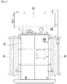
- Fig. 5 is an exemplary representation illustrating the appearance of the oil type transformer according to an embodiment of the present invention when viewed from the front
- Fig. 6 is an exemplary representation illustrating the appearance of an oil type transformer according to an embodiment of the present invention when viewed from the side
- Fig. 7 is an exemplary representation illustrating the appearance of an oil type transformer according to an embodiment of the present invention when viewed from the top
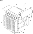
- Fig. 8 is a perspective view of an example of the appearance of an oil type transformer according to an embodiment of the present invention.
- Fig. 9 is an exemplary representation illustrating a plurality of low voltage bushings when viewed from the top
- Fig. 10 is an exemplary representation illustrating operation of a top cover of the plurality of low voltage bushings.
- the oil type phase shift transformer 1 according to an embodiment of the present invention comprises a tank 30 for providing an internal space in which the core 10 and the windings 13, 15 are arranged and also comprises a cover 35 provided on the top of the tank 30.
- the tank 30 and the cover 35 may provide a sealed internal space.
- the first winding 13 and the second winding 15 are arranged inside the tank 30 filled with the insulating oil.
- a high voltage bushing 20 which is connected to the first high voltage winding 13 may be disposed by the side of the tank 30 while a plurality of low voltage bushings 25 which are connected to the second low voltage winding 15 may be disposed on the cover 35.
- the plurality of low voltage bushings 25 are to supply three phase voltage to the plurality of unit power cells 2 wherein three low voltage bushings 25 may be connected to a single power cell 2.
- low pressure bushings 25 are shown as having been designed, but it is apparent that the present invention is not limited to those number. That is, various number of the low voltage bushings 25 may be provided depending on output of the inverter.
- the tank 30 may have a structure such as a welded steel vessel. By virtue of such structure, the transformer 1 can be lifted or moved without any leakage of insulating oil. Further, the cover 35 may be fastened to the tank 30 in a manner of gasket sealing by means of bolts.
- the gasket may be made as a type that can withstand hot oil.
- the front and back surfaces of the tank 30 are provided with radiators 40, 45 for cooling.
- the radiators 40, 45 may be operated such that temperature of the windings 13, 15 or insulating oil does not exceed a certain limit.
- the cover 35 may be provided with an oil conservator 50.
- the oil conservator is to prevent the oil in the oil type transformer 1 from being exposed to the air because the oil can be deteriorated when it contacts with the air.
- a cylindrical vessel of a small volume which is referred to as a conservator 50, is disposed on the top of the tank 30 and connected to the tank 30 such that no air exists in the tank 30. Accordingly, the surface area where the insulating oil contacts with the air becomes small and the air does not directly flow in and out of the tank 30 during respiration of the tank so that deterioration of the insulating oil is prevented.
- a tap changer 55 may be arranged on the top of the cover 35.
- the tap changer 55 may be a no load tap changer (NLTC), but the present invention is not limited thereto.
- Voltage of the transformer 1 can be reset externally through the tap changer 55. That is, a tap of the tap changer 55 can be adjusted during operation of the transformer 1, thereby adjusting voltage of the transformer 1.
- the plurality of low voltage bushings 25 arranged on the top of the cover 35 are shown.
- the plurality of low voltage bushings 25 may be arranged within the housing 60 and an upper cover 65 of the housing 60 may be provided to be opened and closed. By virtue of such configuration, it is possible to change power cells 2 which are connected to the low voltage bushings 25.
- Three low voltage bushings 25 may be connected to a single power cell 2 because voltage input to the single power cell 2 is three phase voltage.
- the oil type phase shift transformer 1 for the inverter system becomes a structure corresponding to IP 54 rating, it can be installed in various places such as indoors or outdoors.
- the transformer 1 can be installed outdoors, it is possible to install only the power cells 2 indoors so that the spatial degrees of freedom are increased and it is also possible to manage separately high voltage devices and low voltage devices.
Landscapes
- Engineering & Computer Science (AREA)
- Power Engineering (AREA)
- Inverter Devices (AREA)
- Transformer Cooling (AREA)
- Supply And Distribution Of Alternating Current (AREA)
- Housings And Mounting Of Transformers (AREA)
Abstract
Description
- The present invention relates to an oil type phase shift transformer for a medium voltage inverter system.
- In general, a voltage type medium voltage inverter is an inverter whose root mean square value of input line-to-line voltage is 600V or more, which is used to drive an electric motor having large capacity of several hundreds of kW to several tens of MW. Such medium voltage inverter is typically configured as a cascaded H-bridge type.
- This medium voltage inverter requires a phase shift transformer in order to provide galvanic isolation and harmonics mitigation to an input terminal and supply input power to each of unit power cells. This phase shift transformer is a very important factor in design of the medium voltage inverter because it occupies the majority of volume and weight of the medium voltage inverter.
- Such phase shift transformer is divided into an oil type transformer and a dry type transformer depending on use of insulating oil. In a conventional medium voltage inverter system, the dry type transformer has been used.
- In the case of the dry type transformer, an identification code for protection is IP20, which is not suitable to be installed outdoors. The first digit in the IP rating indicates a vibration proof level and the second digit indicates a water proof level. In the case of the dry type transformer, it is almost impossible to protect the transformer from dust, in particular water.
- Therefore, in the conventional medium voltage inverter system, the dry type phase shift transformer must be installed indoors in the same way as the unit power cell.
-
Fig. 1 is a configuration diagram of a conventional medium voltage inverter system. - As can be seen from this figure, the
phase shift transformer 200 is contained in a separate panel and disposed by the side of a panel containingpower cells 100. In addition, a forced cooling fan for maintaining temperature of the transformer is required to be installed on the top of the panel. - In the conventional phase shift transformer, there are problems that it is difficult to secure space because the transformer must be an indoor type and that the transformer is significantly affected by surroundings due to characteristics of the forced cooling type thereof.
- It is an aspect of the present invention to provide a phase shift transformer for a medium voltage inverter system, which is configured as an oil type phase shift transformer so that spatial degrees of freedom are secured and high voltage devices and low voltage devices are managed separately.
- The present invention is not limited to the above aspect and other aspects of the present invention will be clearly understood by those skilled in the art from the following description.
- In accordance with one aspect of the present invention for accomplishing the object as mentioned above, a phase shift transformer for supplying voltage to a plurality of unit power cells in a medium voltage inverter system comprises: a first winding which is configured to surround the outside of a core and to which three phase high voltage is applied; a plurality of second windings which are configured to surround the outside of the core and convert high voltage applied thereto from the first winding to low voltage; a tank providing an internal space in which the core, the first winding and the plurality of second windings are arranged and containing insulating oil therein; a cover provided on the top of the tank to provide a sealed internal space along with the tank; a first bushing arranged by the side of the tank and connected to the first winding to apply high voltage; and a plurality of second bushings arranged on the top of the cover and connected to each of the plurality of second windings to output low voltage, wherein three outputs of the plurality of second bushings can be applied to the unit power cells.
- In a preferred embodiment of the present invention, the phase shift transformer may further comprise radiators arranged on the front and back surfaces of the tank to cool the insulating oil or the first winding and the second windings.
- In a preferred embodiment of the present invention, the phase shift transformer may further comprise a tap changer arranged on the top of the cover to control voltage variation during operation of the phase shift transformer.
- In a preferred embodiment of the present invention, the phase shift transformer may further comprise a housing in which the plurality of low voltage bushings are arranged, wherein the housing can be provided such that a top cover is capable of being opened and closed.
- According to the present invention as described above, the transformer can be installed outdoors and hence it is possible to minimize indoor area for installing the transformer by installing only the unit power cells indoors. Therefore, there are advantageous effects that spatial degrees of freedom in the design of the medium voltage inverter system are increased and that it is possible to manage separately high voltage devices and low voltage devices.
-
-
Fig. 1 is a configuration diagram of a conventional medium voltage inverter system. -
Fig. 2 is a configuration diagram illustrating schematically a medium voltage inverter system to which the present invention is applied. -
Fig. 3 is an exemplary representation illustrating the medium voltage inverter system which is implemented indoors in accordance with the present invention. -
Fig. 4 is an exemplary representation illustrating windings and a core which are implemented in the interior of an oil type transformer according to the present invention. -
Fig. 5 is an exemplary representation illustrating the appearance of an oil type transformer according to an embodiment of the present invention when viewed from the front. -
Fig. 6 is an exemplary representation illustrating the appearance of the oil type transformer according to an embodiment of the present invention when viewed from the side. -
Fig. 7 is an exemplary representation illustrating the appearance of the oil type transformer according to an embodiment of the present invention when viewed from the top. -
Fig. 8 is a perspective view of an example of the appearance of the oil type transformer according to an embodiment of the present invention. -
Fig. 9 is an exemplary representation illustrating a plurality of low voltage bushings when viewed from the top. -
Fig. 10 is an exemplary representation illustrating operation of a top cover of the plurality of low voltage bushings. - As the present invention may have different embodiments and various modifications thereto, specific embodiments are illustrated in the drawings and described in detail in the following description. This, however, is by no means to restrict the present invention to the specific embodiments, it is to be understood to include all changes, equivalents, and substitutes falling within the spirit and scope of the present invention.
- Preferred embodiments of the present invention will now be described in detail with reference to the accompanying drawings. In this process, sizes or shapes of constituent elements shown in the drawings may be exaggerated for clarity and convenience in explanation.
-
Fig. 2 is a configuration diagram illustrating schematically a multi-level medium voltage inverter system to which the present invention is applied. - As shown in the figure, the medium voltage inverter system to which the present invention is applied comprises an oil type
phase shift transformer 1 and a plurality ofunit power cells 2 according to an embodiment of the present invention. The resulting voltage output from the plurality ofunit power cells 2 can be output to a three phaseelectric motor 3. - The
phase shift transformer 1, of which primary side input is about 3 to 11kV and secondary side output is about 635V, may be composed of a plurality of coils. - A plurality of
unit power cells 2 may stack secondary side voltages to make up a variable output to apply to an electric motor. -
Fig. 3 is an exemplary representation illustrating the medium voltage inverter system which is implemented indoors in accordance with the present invention. - As shown in the figure, as the
phase shift transformer 1 is configured as an oil type phase shift transformer, there is no need for the phase shift transformer to be installed indoors and thus, it is possible to place only a panel containing the plurality ofunit power cells 2 indoors. Therefore, it can be seen that spatial degrees of freedom are increased because of no requirement for the space where thephase shift transformer 1 has been placed. -
Fig. 4 is an exemplary representation illustrating windings and a core which are implemented in the interior of an oil type transformer according to the present invention. - As shown in the figure,
windings core 10, wherein the windings include a primary winding 13 (hereinafter, referred to as "first winding") and a secondary winding 15 (hereinafter, referred to as "second winding"). Structure of thesecond winding 15 may be determined depending on the number ofunit power cells 2. - Three phase voltage of about 3 to 11kV may be applied to three
high voltage bushings 20, and then voltage of 635V may be output to a plurality oflow voltage bushings 25 through the second winding 15 via thefirst winding 13. In this case, the "high voltage bushing" means a connection element for applying high voltage power to be supplied from the outside to the windings, which is also referred to as a "primary bushing." In addition, the "low voltage bushing" means a connection element for drawing out the transformed low voltage power to the outside, which is also referred to as a "secondary bushing." - The
core 10 may be formed in a shell type andwindings - These windings and core may be contained in a tank filled with insulating oil, as described later.
- Hereinafter, external constitution of the oil type transformer will be described with reference to the drawings.
-
Fig. 5 is an exemplary representation illustrating the appearance of the oil type transformer according to an embodiment of the present invention when viewed from the front,Fig. 6 is an exemplary representation illustrating the appearance of an oil type transformer according to an embodiment of the present invention when viewed from the side, andFig. 7 is an exemplary representation illustrating the appearance of an oil type transformer according to an embodiment of the present invention when viewed from the top.Fig. 8 is a perspective view of an example of the appearance of an oil type transformer according to an embodiment of the present invention. Furthermore,Fig. 9 is an exemplary representation illustrating a plurality of low voltage bushings when viewed from the top andFig. 10 is an exemplary representation illustrating operation of a top cover of the plurality of low voltage bushings. - As shown in the figures, the oil type
phase shift transformer 1 according to an embodiment of the present invention comprises atank 30 for providing an internal space in which thecore 10 and thewindings cover 35 provided on the top of thetank 30. Thetank 30 and thecover 35 may provide a sealed internal space. - The first winding 13 and the second winding 15 are arranged inside the
tank 30 filled with the insulating oil. - A
high voltage bushing 20 which is connected to the first high voltage winding 13 may be disposed by the side of thetank 30 while a plurality oflow voltage bushings 25 which are connected to the second low voltage winding 15 may be disposed on thecover 35. The plurality oflow voltage bushings 25 are to supply three phase voltage to the plurality ofunit power cells 2 wherein threelow voltage bushings 25 may be connected to asingle power cell 2. - In this embodiment of the present invention, 54
low pressure bushings 25 are shown as having been designed, but it is apparent that the present invention is not limited to those number. That is, various number of thelow voltage bushings 25 may be provided depending on output of the inverter. - The
tank 30 may have a structure such as a welded steel vessel. By virtue of such structure, thetransformer 1 can be lifted or moved without any leakage of insulating oil. Further, thecover 35 may be fastened to thetank 30 in a manner of gasket sealing by means of bolts. The gasket may be made as a type that can withstand hot oil. - The front and back surfaces of the
tank 30 are provided withradiators radiators windings - One side of the
cover 35 may be provided with anoil conservator 50. The oil conservator is to prevent the oil in theoil type transformer 1 from being exposed to the air because the oil can be deteriorated when it contacts with the air. In other words, a cylindrical vessel of a small volume, which is referred to as aconservator 50, is disposed on the top of thetank 30 and connected to thetank 30 such that no air exists in thetank 30. Accordingly, the surface area where the insulating oil contacts with the air becomes small and the air does not directly flow in and out of thetank 30 during respiration of the tank so that deterioration of the insulating oil is prevented. - A
tap changer 55 may be arranged on the top of thecover 35. In an embodiment of the invention, thetap changer 55 may be a no load tap changer (NLTC), but the present invention is not limited thereto. Voltage of thetransformer 1 can be reset externally through thetap changer 55. That is, a tap of thetap changer 55 can be adjusted during operation of thetransformer 1, thereby adjusting voltage of thetransformer 1. - Referring to
Figs. 9 and 10 , the plurality oflow voltage bushings 25 arranged on the top of thecover 35 are shown. The plurality oflow voltage bushings 25 may be arranged within thehousing 60 and anupper cover 65 of thehousing 60 may be provided to be opened and closed. By virtue of such configuration, it is possible to changepower cells 2 which are connected to thelow voltage bushings 25. - Three
low voltage bushings 25 may be connected to asingle power cell 2 because voltage input to thesingle power cell 2 is three phase voltage. - As the oil type
phase shift transformer 1 for the inverter system, according to the present invention, becomes a structure corresponding to IP 54 rating, it can be installed in various places such as indoors or outdoors. - Therefore, as the
transformer 1 can be installed outdoors, it is possible to install only thepower cells 2 indoors so that the spatial degrees of freedom are increased and it is also possible to manage separately high voltage devices and low voltage devices. - In the foregoing description, preferred embodiments according to the present invention are described, but they are merely exemplary examples of the invention. It is to be understood by those having ordinary skill in the art that various modifications and other embodiment equivalent to the invention can be made from the details discussed above. Therefore, the true scope of the present invention should be defined by the appended claims.
Claims (4)
- A phase shift transformer (1) for supplying voltage to a plurality of unit power cells (2) in a medium voltage inverter system, comprising:a first winding (13) which is configured to surround the outside of a core (10) and to which three phase high voltage is applied;a plurality of second windings (15) which are configured to surround the outside of the core (10) and convert high voltage applied thereto from the first winding (13) to low voltage;a tank (30) providing an internal space in which the core (10), the first winding (13) and the plurality of second windings (15) are arranged and containing insulating oil therein;a cover (35) provided on the top of the tank (30) to provide a sealed internal space along with the tank (30);a first bushing (20) arranged by the side of the tank (30) and connected to the first winding (13) to apply high voltage; anda plurality of second bushings (25) arranged on the top of the cover (35) and connected to each of the plurality of second windings (15) to output low voltage,wherein three outputs of the plurality of second bushings (25) can be applied to the unit power cells (2).
- The phase shift transformer (1) of claim 1, further comprising radiators (40, 45) arranged on the front and back surfaces of the tank (30) to cool the insulating oil or the first winding (13) and the second windings (15).
- The phase shift transformer (1) of claim 1, further comprising a tap changer (55) arranged on the top of the cover (35) to control voltage variation during operation of the phase shift transformer (1).
- The phase shift transformer (1) of claim 1, further comprising a housing (60) in which the plurality of second bushings (25) are arranged, wherein the housing (60) can be provided such that a top cover (65) thereof is capable of being opened and closed.
Applications Claiming Priority (1)
| Application Number | Priority Date | Filing Date | Title |
|---|---|---|---|
| KR1020160041626A KR101768849B1 (en) | 2016-04-05 | 2016-04-05 | Oil type phase shift transformer in medium voltage inverter system |
Publications (2)
| Publication Number | Publication Date |
|---|---|
| EP3229246A1 true EP3229246A1 (en) | 2017-10-11 |
| EP3229246B1 EP3229246B1 (en) | 2022-09-28 |
Family
ID=57421782
Family Applications (1)
| Application Number | Title | Priority Date | Filing Date |
|---|---|---|---|
| EP16201174.6A Active EP3229246B1 (en) | 2016-04-05 | 2016-11-29 | Oil type phase shift transformer assembly for medium voltage inverter system |
Country Status (6)
| Country | Link |
|---|---|
| US (1) | US10069437B2 (en) |
| EP (1) | EP3229246B1 (en) |
| JP (1) | JP2017188650A (en) |
| KR (1) | KR101768849B1 (en) |
| CN (1) | CN107275062A (en) |
| ES (1) | ES2929024T3 (en) |
Cited By (1)
| Publication number | Priority date | Publication date | Assignee | Title |
|---|---|---|---|---|
| EP4697368A1 (en) * | 2024-08-13 | 2026-02-18 | Hitachi Energy Ltd | Cooling system for a heat generating electric component |
Families Citing this family (2)
| Publication number | Priority date | Publication date | Assignee | Title |
|---|---|---|---|---|
| CN108735461A (en) * | 2018-05-06 | 2018-11-02 | 江苏创凌非晶科技发展有限公司 | dry-type transformer |
| CN114755544A (en) * | 2022-05-07 | 2022-07-15 | 国网新疆电力有限公司电力科学研究院 | All-in-one sensing device for transformer bushing tap monitoring |
Citations (3)
| Publication number | Priority date | Publication date | Assignee | Title |
|---|---|---|---|---|
| US20120043922A1 (en) * | 2010-08-23 | 2012-02-23 | Schlumberger Technology Corporation | Variable Freqency Drive with Dielectric Fluid-Immersed Transformer |
| CN203013471U (en) * | 2012-12-13 | 2013-06-19 | 北京合康亿盛变频科技股份有限公司 | Centralized type connecting box and oil tank of phase-shifting transformer special for frequency converter |
| CN205016009U (en) * | 2015-10-17 | 2016-02-03 | 北京普锐电子有限公司 | Transformer intelligence anti -theft device |
Family Cites Families (29)
| Publication number | Priority date | Publication date | Assignee | Title |
|---|---|---|---|---|
| US2360801A (en) * | 1940-09-21 | 1944-10-17 | Line Material Co | Switch operating mechanism |
| US2600979A (en) * | 1947-07-28 | 1952-06-17 | Gen Electric | Insulating bushing with pressurelimiting means |
| US3028568A (en) * | 1960-09-28 | 1962-04-03 | Gen Electric | Potential transformer |
| US3333221A (en) * | 1962-12-03 | 1967-07-25 | Westinghouse Electric Corp | Transformer having temperature responsive leakage reactance |
| US3541487A (en) * | 1968-11-18 | 1970-11-17 | Westinghouse Electric Corp | Electrical winding having heat exchangers between layers of the winding for cooling the windings |
| US3564386A (en) * | 1968-12-27 | 1971-02-16 | Westinghouse Electric Corp | Power supply for converting high voltage alternating current into high voltage direct current |
| JPS4911868A (en) | 1972-05-17 | 1974-02-01 | ||
| JPS4982927A (en) * | 1972-12-18 | 1974-08-09 | ||
| JP2520902Y2 (en) * | 1991-04-03 | 1996-12-18 | 株式会社フクダセイコー | Primary side bushing cover for pole transformer |
| JPH06112052A (en) * | 1992-09-29 | 1994-04-22 | Toshiba Corp | Transformer |
| JP3127077B2 (en) * | 1994-04-26 | 2001-01-22 | 株式会社日立製作所 | Stationary induction appliance |
| JPH0817661A (en) * | 1994-06-29 | 1996-01-19 | Toshiba Corp | Conversion transformer device and transportation method thereof |
| US5804954A (en) * | 1995-06-26 | 1998-09-08 | Siemens Energy & Automation, Inc. | Analog based tap position detector |
| JP3143066B2 (en) * | 1996-07-19 | 2001-03-07 | 株式会社日立製作所 | Oil-filled electrical equipment |
| IT1299218B1 (en) * | 1998-05-11 | 2000-02-29 | Abb Trasformatori S P A | POWER AND / OR DISTRIBUTION TRANSFORMER EQUIPPED WITH SWITCH UNDER LOAD |
| JP4177000B2 (en) * | 2002-02-15 | 2008-11-05 | 株式会社ダイヘン | Bushing protection cover and bushing protection method for power transformer |
| KR100802627B1 (en) | 2004-05-12 | 2008-02-14 | 주식회사 오.엘.티 | Oil forced chiller of transformer |
| KR20080067320A (en) | 2008-06-30 | 2008-07-18 | 임성황 | Inlet transformer with radiator on top of oil tank |
| US7830681B2 (en) | 2008-09-24 | 2010-11-09 | Teco-Westinghouse Motor Company | Modular multi-pulse transformer rectifier for use in asymmetric multi-level power converter |
| KR100995709B1 (en) | 2008-12-23 | 2010-11-19 | 한국전기연구원 | Inrush Transformer Load Management System |
| CN201616328U (en) * | 2010-02-26 | 2010-10-27 | 辽宁三川电气设备有限公司 | Dual-voltage power transformer |
| JP5681960B2 (en) * | 2011-03-03 | 2015-03-11 | 株式会社ダイヘン | Bushing terminal cover |
| US9099914B2 (en) * | 2011-06-29 | 2015-08-04 | Siemens Aktiengesellschaft | Packaging of power supply using modular electronic modules |
| KR101260608B1 (en) * | 2011-09-26 | 2013-05-03 | 엘에스산전 주식회사 | Method for compensating instantaneous power failure in medium voltage inverter and medium voltage inverter system by using the same |
| JP2014027150A (en) | 2012-07-27 | 2014-02-06 | Hitachi Industrial Equipment Systems Co Ltd | Oil-filled transformer |
| CN203242482U (en) * | 2013-03-23 | 2013-10-16 | 辽宁华冶集团发展有限公司 | 66 kilovolt grounding and station transformer |
| CN203607231U (en) * | 2013-12-11 | 2014-05-21 | 国家电网公司 | Vehicle-mounted mobile transformer |
| JP2015185736A (en) * | 2014-03-25 | 2015-10-22 | 三菱電機株式会社 | Transformer |
| JP2015201560A (en) | 2014-04-09 | 2015-11-12 | 株式会社東芝 | oil-filled transformer |
-
2016
- 2016-04-05 KR KR1020160041626A patent/KR101768849B1/en active Active
- 2016-11-29 EP EP16201174.6A patent/EP3229246B1/en active Active
- 2016-11-29 ES ES16201174T patent/ES2929024T3/en active Active
- 2016-12-01 JP JP2016234569A patent/JP2017188650A/en active Pending
- 2016-12-14 CN CN201611155295.5A patent/CN107275062A/en active Pending
- 2016-12-22 US US15/388,357 patent/US10069437B2/en active Active
Patent Citations (3)
| Publication number | Priority date | Publication date | Assignee | Title |
|---|---|---|---|---|
| US20120043922A1 (en) * | 2010-08-23 | 2012-02-23 | Schlumberger Technology Corporation | Variable Freqency Drive with Dielectric Fluid-Immersed Transformer |
| CN203013471U (en) * | 2012-12-13 | 2013-06-19 | 北京合康亿盛变频科技股份有限公司 | Centralized type connecting box and oil tank of phase-shifting transformer special for frequency converter |
| CN205016009U (en) * | 2015-10-17 | 2016-02-03 | 北京普锐电子有限公司 | Transformer intelligence anti -theft device |
Non-Patent Citations (2)
| Title |
|---|
| "Power Transformers: Principles and Applications", 12 April 2002, CRC PRESS, ISBN: 978-0-8247-0766-8, article JOHN WINDERS: "Two-Winding Transformer Connections", pages: 67, XP055384450 * |
| WEG: "Motors | Automation | Energy | Transmission & Distribution | Coatings MVW01 Medium Voltage Variable Speed Drive", 1 July 2015 (2015-07-01), XP055384466, Retrieved from the Internet <URL:http://ecatalog.weg.net/files/wegnet/WEG-mvw01-medium-voltage-drive-50019088-brochure-english.pdf> [retrieved on 20170623] * |
Cited By (2)
| Publication number | Priority date | Publication date | Assignee | Title |
|---|---|---|---|---|
| EP4697368A1 (en) * | 2024-08-13 | 2026-02-18 | Hitachi Energy Ltd | Cooling system for a heat generating electric component |
| WO2026037856A1 (en) * | 2024-08-13 | 2026-02-19 | Hitachi Energy Ltd | Cooling system for a heat generating electric component |
Also Published As
| Publication number | Publication date |
|---|---|
| KR101768849B1 (en) | 2017-08-17 |
| ES2929024T3 (en) | 2022-11-24 |
| EP3229246B1 (en) | 2022-09-28 |
| CN107275062A (en) | 2017-10-20 |
| US10069437B2 (en) | 2018-09-04 |
| US20170288572A1 (en) | 2017-10-05 |
| JP2017188650A (en) | 2017-10-12 |
Similar Documents
| Publication | Publication Date | Title |
|---|---|---|
| US8013702B2 (en) | Versatile distribution transformer | |
| JP6607137B2 (en) | Power storage device | |
| CA3022259C (en) | Replacement transformer with modular construction | |
| US8093871B2 (en) | Power distribution system control and monitoring | |
| US20110140820A1 (en) | Hyper-cooled liquid-filled transformer | |
| EP3229246B1 (en) | Oil type phase shift transformer assembly for medium voltage inverter system | |
| BG63442B1 (en) | Dc transformer/converter | |
| JP6668128B2 (en) | Reactive power compensator | |
| US20180047499A1 (en) | Distribution transformer and integrated power conditioning device | |
| EP2187408B1 (en) | Iron core reactor | |
| US20170164495A1 (en) | Subsea converter module | |
| KR20070075840A (en) | Waterproof terminal of transformer | |
| KR20230054759A (en) | Uninterruptible Power Appliances for Underwater Applications | |
| RU2667084C2 (en) | Enclosure for voltage transformer and corresponding voltage transformer | |
| Vahidi et al. | Principles and modeling of the power transformers | |
| BR112022026124B1 (en) | POWER TRANSFORMER ASSEMBLY AND APPARATUS FOR MOUNTING INSIDE A POWER TRANSFORMER | |
| KR20150125420A (en) | Oil immersed power transformer | |
| KR102503072B1 (en) | electrostatic induction array | |
| AU2021107158A4 (en) | Sealed dry-type transformer | |
| KR20220134315A (en) | Magnetically controlled reactor for supplying lagging reactive power to power system and reactive power supplying device | |
| EP4379758A1 (en) | Method and transformer arrangement for handling transportation and assembling of a single phase transformer | |
| WO2022096124A1 (en) | A tap changer and a transformer arrangement comprising the tap changer |
Legal Events
| Date | Code | Title | Description |
|---|---|---|---|
| PUAI | Public reference made under article 153(3) epc to a published international application that has entered the european phase |
Free format text: ORIGINAL CODE: 0009012 |
|
| STAA | Information on the status of an ep patent application or granted ep patent |
Free format text: STATUS: THE APPLICATION HAS BEEN PUBLISHED |
|
| AK | Designated contracting states |
Kind code of ref document: A1 Designated state(s): AL AT BE BG CH CY CZ DE DK EE ES FI FR GB GR HR HU IE IS IT LI LT LU LV MC MK MT NL NO PL PT RO RS SE SI SK SM TR |
|
| AX | Request for extension of the european patent |
Extension state: BA ME |
|
| STAA | Information on the status of an ep patent application or granted ep patent |
Free format text: STATUS: REQUEST FOR EXAMINATION WAS MADE |
|
| 17P | Request for examination filed |
Effective date: 20180409 |
|
| RBV | Designated contracting states (corrected) |
Designated state(s): AL AT BE BG CH CY CZ DE DK EE ES FI FR GB GR HR HU IE IS IT LI LT LU LV MC MK MT NL NO PL PT RO RS SE SI SK SM TR |
|
| STAA | Information on the status of an ep patent application or granted ep patent |
Free format text: STATUS: EXAMINATION IS IN PROGRESS |
|
| 17Q | First examination report despatched |
Effective date: 20201209 |
|
| GRAP | Despatch of communication of intention to grant a patent |
Free format text: ORIGINAL CODE: EPIDOSNIGR1 |
|
| STAA | Information on the status of an ep patent application or granted ep patent |
Free format text: STATUS: GRANT OF PATENT IS INTENDED |
|
| INTG | Intention to grant announced |
Effective date: 20220503 |
|
| GRAS | Grant fee paid |
Free format text: ORIGINAL CODE: EPIDOSNIGR3 |
|
| GRAA | (expected) grant |
Free format text: ORIGINAL CODE: 0009210 |
|
| STAA | Information on the status of an ep patent application or granted ep patent |
Free format text: STATUS: THE PATENT HAS BEEN GRANTED |
|
| AK | Designated contracting states |
Kind code of ref document: B1 Designated state(s): AL AT BE BG CH CY CZ DE DK EE ES FI FR GB GR HR HU IE IS IT LI LT LU LV MC MK MT NL NO PL PT RO RS SE SI SK SM TR |
|
| REG | Reference to a national code |
Ref country code: GB Ref legal event code: FG4D |
|
| REG | Reference to a national code |
Ref country code: CH Ref legal event code: EP |
|
| REG | Reference to a national code |
Ref country code: DE Ref legal event code: R096 Ref document number: 602016075251 Country of ref document: DE |
|
| REG | Reference to a national code |
Ref country code: AT Ref legal event code: REF Ref document number: 1521789 Country of ref document: AT Kind code of ref document: T Effective date: 20221015 |
|
| REG | Reference to a national code |
Ref country code: IE Ref legal event code: FG4D |
|
| REG | Reference to a national code |
Ref country code: ES Ref legal event code: FG2A Ref document number: 2929024 Country of ref document: ES Kind code of ref document: T3 Effective date: 20221124 |
|
| REG | Reference to a national code |
Ref country code: LT Ref legal event code: MG9D |
|
| PG25 | Lapsed in a contracting state [announced via postgrant information from national office to epo] |
Ref country code: SE Free format text: LAPSE BECAUSE OF FAILURE TO SUBMIT A TRANSLATION OF THE DESCRIPTION OR TO PAY THE FEE WITHIN THE PRESCRIBED TIME-LIMIT Effective date: 20220928 Ref country code: RS Free format text: LAPSE BECAUSE OF FAILURE TO SUBMIT A TRANSLATION OF THE DESCRIPTION OR TO PAY THE FEE WITHIN THE PRESCRIBED TIME-LIMIT Effective date: 20220928 Ref country code: NO Free format text: LAPSE BECAUSE OF FAILURE TO SUBMIT A TRANSLATION OF THE DESCRIPTION OR TO PAY THE FEE WITHIN THE PRESCRIBED TIME-LIMIT Effective date: 20221228 Ref country code: LV Free format text: LAPSE BECAUSE OF FAILURE TO SUBMIT A TRANSLATION OF THE DESCRIPTION OR TO PAY THE FEE WITHIN THE PRESCRIBED TIME-LIMIT Effective date: 20220928 Ref country code: LT Free format text: LAPSE BECAUSE OF FAILURE TO SUBMIT A TRANSLATION OF THE DESCRIPTION OR TO PAY THE FEE WITHIN THE PRESCRIBED TIME-LIMIT Effective date: 20220928 Ref country code: FI Free format text: LAPSE BECAUSE OF FAILURE TO SUBMIT A TRANSLATION OF THE DESCRIPTION OR TO PAY THE FEE WITHIN THE PRESCRIBED TIME-LIMIT Effective date: 20220928 |
|
| REG | Reference to a national code |
Ref country code: NL Ref legal event code: MP Effective date: 20220928 |
|
| REG | Reference to a national code |
Ref country code: AT Ref legal event code: MK05 Ref document number: 1521789 Country of ref document: AT Kind code of ref document: T Effective date: 20220928 |
|
| PG25 | Lapsed in a contracting state [announced via postgrant information from national office to epo] |
Ref country code: HR Free format text: LAPSE BECAUSE OF FAILURE TO SUBMIT A TRANSLATION OF THE DESCRIPTION OR TO PAY THE FEE WITHIN THE PRESCRIBED TIME-LIMIT Effective date: 20220928 Ref country code: GR Free format text: LAPSE BECAUSE OF FAILURE TO SUBMIT A TRANSLATION OF THE DESCRIPTION OR TO PAY THE FEE WITHIN THE PRESCRIBED TIME-LIMIT Effective date: 20221229 |
|
| PG25 | Lapsed in a contracting state [announced via postgrant information from national office to epo] |
Ref country code: SM Free format text: LAPSE BECAUSE OF FAILURE TO SUBMIT A TRANSLATION OF THE DESCRIPTION OR TO PAY THE FEE WITHIN THE PRESCRIBED TIME-LIMIT Effective date: 20220928 Ref country code: RO Free format text: LAPSE BECAUSE OF FAILURE TO SUBMIT A TRANSLATION OF THE DESCRIPTION OR TO PAY THE FEE WITHIN THE PRESCRIBED TIME-LIMIT Effective date: 20220928 Ref country code: PT Free format text: LAPSE BECAUSE OF FAILURE TO SUBMIT A TRANSLATION OF THE DESCRIPTION OR TO PAY THE FEE WITHIN THE PRESCRIBED TIME-LIMIT Effective date: 20230130 Ref country code: CZ Free format text: LAPSE BECAUSE OF FAILURE TO SUBMIT A TRANSLATION OF THE DESCRIPTION OR TO PAY THE FEE WITHIN THE PRESCRIBED TIME-LIMIT Effective date: 20220928 Ref country code: AT Free format text: LAPSE BECAUSE OF FAILURE TO SUBMIT A TRANSLATION OF THE DESCRIPTION OR TO PAY THE FEE WITHIN THE PRESCRIBED TIME-LIMIT Effective date: 20220928 |
|
| PG25 | Lapsed in a contracting state [announced via postgrant information from national office to epo] |
Ref country code: SK Free format text: LAPSE BECAUSE OF FAILURE TO SUBMIT A TRANSLATION OF THE DESCRIPTION OR TO PAY THE FEE WITHIN THE PRESCRIBED TIME-LIMIT Effective date: 20220928 Ref country code: PL Free format text: LAPSE BECAUSE OF FAILURE TO SUBMIT A TRANSLATION OF THE DESCRIPTION OR TO PAY THE FEE WITHIN THE PRESCRIBED TIME-LIMIT Effective date: 20220928 Ref country code: IS Free format text: LAPSE BECAUSE OF FAILURE TO SUBMIT A TRANSLATION OF THE DESCRIPTION OR TO PAY THE FEE WITHIN THE PRESCRIBED TIME-LIMIT Effective date: 20230128 Ref country code: EE Free format text: LAPSE BECAUSE OF FAILURE TO SUBMIT A TRANSLATION OF THE DESCRIPTION OR TO PAY THE FEE WITHIN THE PRESCRIBED TIME-LIMIT Effective date: 20220928 |
|
| REG | Reference to a national code |
Ref country code: DE Ref legal event code: R097 Ref document number: 602016075251 Country of ref document: DE |
|
| PG25 | Lapsed in a contracting state [announced via postgrant information from national office to epo] |
Ref country code: NL Free format text: LAPSE BECAUSE OF FAILURE TO SUBMIT A TRANSLATION OF THE DESCRIPTION OR TO PAY THE FEE WITHIN THE PRESCRIBED TIME-LIMIT Effective date: 20220928 Ref country code: MC Free format text: LAPSE BECAUSE OF FAILURE TO SUBMIT A TRANSLATION OF THE DESCRIPTION OR TO PAY THE FEE WITHIN THE PRESCRIBED TIME-LIMIT Effective date: 20220928 Ref country code: AL Free format text: LAPSE BECAUSE OF FAILURE TO SUBMIT A TRANSLATION OF THE DESCRIPTION OR TO PAY THE FEE WITHIN THE PRESCRIBED TIME-LIMIT Effective date: 20220928 |
|
| REG | Reference to a national code |
Ref country code: CH Ref legal event code: PL |
|
| REG | Reference to a national code |
Ref country code: BE Ref legal event code: MM Effective date: 20221130 |
|
| PG25 | Lapsed in a contracting state [announced via postgrant information from national office to epo] |
Ref country code: LI Free format text: LAPSE BECAUSE OF NON-PAYMENT OF DUE FEES Effective date: 20221130 Ref country code: DK Free format text: LAPSE BECAUSE OF FAILURE TO SUBMIT A TRANSLATION OF THE DESCRIPTION OR TO PAY THE FEE WITHIN THE PRESCRIBED TIME-LIMIT Effective date: 20220928 Ref country code: CH Free format text: LAPSE BECAUSE OF NON-PAYMENT OF DUE FEES Effective date: 20221130 |
|
| P01 | Opt-out of the competence of the unified patent court (upc) registered |
Effective date: 20230625 |
|
| PLBE | No opposition filed within time limit |
Free format text: ORIGINAL CODE: 0009261 |
|
| STAA | Information on the status of an ep patent application or granted ep patent |
Free format text: STATUS: NO OPPOSITION FILED WITHIN TIME LIMIT |
|
| PG25 | Lapsed in a contracting state [announced via postgrant information from national office to epo] |
Ref country code: LU Free format text: LAPSE BECAUSE OF NON-PAYMENT OF DUE FEES Effective date: 20221129 |
|
| 26N | No opposition filed |
Effective date: 20230629 |
|
| PG25 | Lapsed in a contracting state [announced via postgrant information from national office to epo] |
Ref country code: IE Free format text: LAPSE BECAUSE OF NON-PAYMENT OF DUE FEES Effective date: 20221129 |
|
| PG25 | Lapsed in a contracting state [announced via postgrant information from national office to epo] |
Ref country code: SI Free format text: LAPSE BECAUSE OF FAILURE TO SUBMIT A TRANSLATION OF THE DESCRIPTION OR TO PAY THE FEE WITHIN THE PRESCRIBED TIME-LIMIT Effective date: 20220928 Ref country code: FR Free format text: LAPSE BECAUSE OF NON-PAYMENT OF DUE FEES Effective date: 20221130 Ref country code: BE Free format text: LAPSE BECAUSE OF NON-PAYMENT OF DUE FEES Effective date: 20221130 |
|
| PG25 | Lapsed in a contracting state [announced via postgrant information from national office to epo] |
Ref country code: HU Free format text: LAPSE BECAUSE OF FAILURE TO SUBMIT A TRANSLATION OF THE DESCRIPTION OR TO PAY THE FEE WITHIN THE PRESCRIBED TIME-LIMIT; INVALID AB INITIO Effective date: 20161129 |
|
| PG25 | Lapsed in a contracting state [announced via postgrant information from national office to epo] |
Ref country code: CY Free format text: LAPSE BECAUSE OF FAILURE TO SUBMIT A TRANSLATION OF THE DESCRIPTION OR TO PAY THE FEE WITHIN THE PRESCRIBED TIME-LIMIT Effective date: 20220928 |
|
| PG25 | Lapsed in a contracting state [announced via postgrant information from national office to epo] |
Ref country code: MK Free format text: LAPSE BECAUSE OF FAILURE TO SUBMIT A TRANSLATION OF THE DESCRIPTION OR TO PAY THE FEE WITHIN THE PRESCRIBED TIME-LIMIT Effective date: 20220928 |
|
| PG25 | Lapsed in a contracting state [announced via postgrant information from national office to epo] |
Ref country code: BG Free format text: LAPSE BECAUSE OF FAILURE TO SUBMIT A TRANSLATION OF THE DESCRIPTION OR TO PAY THE FEE WITHIN THE PRESCRIBED TIME-LIMIT Effective date: 20220928 |
|
| PG25 | Lapsed in a contracting state [announced via postgrant information from national office to epo] |
Ref country code: MT Free format text: LAPSE BECAUSE OF FAILURE TO SUBMIT A TRANSLATION OF THE DESCRIPTION OR TO PAY THE FEE WITHIN THE PRESCRIBED TIME-LIMIT Effective date: 20220928 |
|
| PGFP | Annual fee paid to national office [announced via postgrant information from national office to epo] |
Ref country code: IT Payment date: 20250909 Year of fee payment: 10 |
|
| PGFP | Annual fee paid to national office [announced via postgrant information from national office to epo] |
Ref country code: GB Payment date: 20250909 Year of fee payment: 10 |
|
| PG25 | Lapsed in a contracting state [announced via postgrant information from national office to epo] |
Ref country code: TR Free format text: LAPSE BECAUSE OF FAILURE TO SUBMIT A TRANSLATION OF THE DESCRIPTION OR TO PAY THE FEE WITHIN THE PRESCRIBED TIME-LIMIT Effective date: 20220928 |
|
| PGFP | Annual fee paid to national office [announced via postgrant information from national office to epo] |
Ref country code: DE Payment date: 20250908 Year of fee payment: 10 |
|
| PGFP | Annual fee paid to national office [announced via postgrant information from national office to epo] |
Ref country code: ES Payment date: 20251215 Year of fee payment: 10 |