EP3229016A1 - Device and method used for removing inorganic carbon, and apparatus and method used for detecting total organic carbon - Google Patents
Device and method used for removing inorganic carbon, and apparatus and method used for detecting total organic carbon Download PDFInfo
- Publication number
- EP3229016A1 EP3229016A1 EP15865044.0A EP15865044A EP3229016A1 EP 3229016 A1 EP3229016 A1 EP 3229016A1 EP 15865044 A EP15865044 A EP 15865044A EP 3229016 A1 EP3229016 A1 EP 3229016A1
- Authority
- EP
- European Patent Office
- Prior art keywords
- carbon
- compartment
- total organic
- concentration
- inorganic carbon
- Prior art date
- Legal status (The legal status is an assumption and is not a legal conclusion. Google has not performed a legal analysis and makes no representation as to the accuracy of the status listed.)
- Withdrawn
Links
- OKTJSMMVPCPJKN-UHFFFAOYSA-N Carbon Chemical compound [C] OKTJSMMVPCPJKN-UHFFFAOYSA-N 0.000 title claims abstract description 107
- 229910052799 carbon Inorganic materials 0.000 title claims abstract description 107
- 238000000034 method Methods 0.000 title claims abstract description 24
- CURLTUGMZLYLDI-UHFFFAOYSA-N Carbon dioxide Chemical compound O=C=O CURLTUGMZLYLDI-UHFFFAOYSA-N 0.000 claims abstract description 46
- 229910002092 carbon dioxide Inorganic materials 0.000 claims abstract description 24
- 239000001569 carbon dioxide Substances 0.000 claims abstract description 22
- 239000003153 chemical reaction reagent Substances 0.000 claims 2
- 239000012855 volatile organic compound Substances 0.000 claims 2
- XLYOFNOQVPJJNP-UHFFFAOYSA-N water Substances O XLYOFNOQVPJJNP-UHFFFAOYSA-N 0.000 abstract description 8
- HEDRZPFGACZZDS-UHFFFAOYSA-N Chloroform Chemical compound ClC(Cl)Cl HEDRZPFGACZZDS-UHFFFAOYSA-N 0.000 description 18
- NBIIXXVUZAFLBC-UHFFFAOYSA-N Phosphoric acid Chemical compound OP(O)(O)=O NBIIXXVUZAFLBC-UHFFFAOYSA-N 0.000 description 8
- HEMHJVSKTPXQMS-UHFFFAOYSA-M Sodium hydroxide Chemical compound [OH-].[Na+] HEMHJVSKTPXQMS-UHFFFAOYSA-M 0.000 description 6
- 230000000052 comparative effect Effects 0.000 description 6
- -1 Polypropylene Polymers 0.000 description 5
- 239000000376 reactant Substances 0.000 description 5
- KCXVZYZYPLLWCC-UHFFFAOYSA-N EDTA Chemical compound OC(=O)CN(CC(O)=O)CCN(CC(O)=O)CC(O)=O KCXVZYZYPLLWCC-UHFFFAOYSA-N 0.000 description 4
- 229910000147 aluminium phosphate Inorganic materials 0.000 description 4
- 238000005259 measurement Methods 0.000 description 4
- WMFOQBRAJBCJND-UHFFFAOYSA-M Lithium hydroxide Chemical compound [Li+].[OH-] WMFOQBRAJBCJND-UHFFFAOYSA-M 0.000 description 3
- KWYUFKZDYYNOTN-UHFFFAOYSA-M Potassium hydroxide Chemical compound [OH-].[K+] KWYUFKZDYYNOTN-UHFFFAOYSA-M 0.000 description 3
- KRKNYBCHXYNGOX-UHFFFAOYSA-N citric acid Chemical compound OC(=O)CC(O)(C(O)=O)CC(O)=O KRKNYBCHXYNGOX-UHFFFAOYSA-N 0.000 description 3
- 238000012986 modification Methods 0.000 description 3
- 230000004048 modification Effects 0.000 description 3
- VEXZGXHMUGYJMC-UHFFFAOYSA-N Hydrochloric acid Chemical compound Cl VEXZGXHMUGYJMC-UHFFFAOYSA-N 0.000 description 2
- QAOWNCQODCNURD-UHFFFAOYSA-N Sulfuric acid Chemical compound OS(O)(=O)=O QAOWNCQODCNURD-UHFFFAOYSA-N 0.000 description 2
- 239000004809 Teflon Substances 0.000 description 2
- 229920006362 Teflon® Polymers 0.000 description 2
- 238000010521 absorption reaction Methods 0.000 description 2
- 239000002253 acid Substances 0.000 description 2
- 150000001875 compounds Chemical class 0.000 description 2
- 239000000463 material Substances 0.000 description 2
- 238000003756 stirring Methods 0.000 description 2
- 239000000126 substance Substances 0.000 description 2
- WKVMOQXBMPYPGK-UHFFFAOYSA-N 2-[bis(carboxymethyl)amino]acetic acid;sodium Chemical compound [Na].OC(=O)CN(CC(O)=O)CC(O)=O WKVMOQXBMPYPGK-UHFFFAOYSA-N 0.000 description 1
- RPNUMPOLZDHAAY-UHFFFAOYSA-N Diethylenetriamine Chemical compound NCCNCCN RPNUMPOLZDHAAY-UHFFFAOYSA-N 0.000 description 1
- 239000003109 Disodium ethylene diamine tetraacetate Substances 0.000 description 1
- DGAQECJNVWCQMB-PUAWFVPOSA-M Ilexoside XXIX Chemical compound C[C@@H]1CC[C@@]2(CC[C@@]3(C(=CC[C@H]4[C@]3(CC[C@@H]5[C@@]4(CC[C@@H](C5(C)C)OS(=O)(=O)[O-])C)C)[C@@H]2[C@]1(C)O)C)C(=O)O[C@H]6[C@@H]([C@H]([C@@H]([C@H](O6)CO)O)O)O.[Na+] DGAQECJNVWCQMB-PUAWFVPOSA-M 0.000 description 1
- 229910019142 PO4 Inorganic materials 0.000 description 1
- 239000004698 Polyethylene Substances 0.000 description 1
- 239000004743 Polypropylene Substances 0.000 description 1
- 239000003513 alkali Substances 0.000 description 1
- 238000013459 approach Methods 0.000 description 1
- 230000003197 catalytic effect Effects 0.000 description 1
- 238000002485 combustion reaction Methods 0.000 description 1
- 235000019301 disodium ethylene diamine tetraacetate Nutrition 0.000 description 1
- DUYCTCQXNHFCSJ-UHFFFAOYSA-N dtpmp Chemical class OP(=O)(O)CN(CP(O)(O)=O)CCN(CP(O)(=O)O)CCN(CP(O)(O)=O)CP(O)(O)=O DUYCTCQXNHFCSJ-UHFFFAOYSA-N 0.000 description 1
- NFDRPXJGHKJRLJ-UHFFFAOYSA-N edtmp Chemical compound OP(O)(=O)CN(CP(O)(O)=O)CCN(CP(O)(O)=O)CP(O)(O)=O NFDRPXJGHKJRLJ-UHFFFAOYSA-N 0.000 description 1
- 229940071106 ethylenediaminetetraacetate Drugs 0.000 description 1
- 230000007717 exclusion Effects 0.000 description 1
- 239000011521 glass Substances 0.000 description 1
- 239000007788 liquid Substances 0.000 description 1
- 239000012528 membrane Substances 0.000 description 1
- 239000000203 mixture Substances 0.000 description 1
- 239000007800 oxidant agent Substances 0.000 description 1
- 230000003647 oxidation Effects 0.000 description 1
- 238000007254 oxidation reaction Methods 0.000 description 1
- 230000001590 oxidative effect Effects 0.000 description 1
- JRKICGRDRMAZLK-UHFFFAOYSA-L peroxydisulfate Chemical compound [O-]S(=O)(=O)OOS([O-])(=O)=O JRKICGRDRMAZLK-UHFFFAOYSA-L 0.000 description 1
- 235000021317 phosphate Nutrition 0.000 description 1
- 229920000573 polyethylene Polymers 0.000 description 1
- 229920001155 polypropylene Polymers 0.000 description 1
- 229920001343 polytetrafluoroethylene Polymers 0.000 description 1
- 239000004810 polytetrafluoroethylene Substances 0.000 description 1
- 238000010926 purge Methods 0.000 description 1
- 230000009467 reduction Effects 0.000 description 1
- 150000003839 salts Chemical class 0.000 description 1
- 238000004062 sedimentation Methods 0.000 description 1
- 229910052708 sodium Inorganic materials 0.000 description 1
- 239000011734 sodium Substances 0.000 description 1
- UEUXEKPTXMALOB-UHFFFAOYSA-J tetrasodium;2-[2-[bis(carboxylatomethyl)amino]ethyl-(carboxylatomethyl)amino]acetate Chemical compound [Na+].[Na+].[Na+].[Na+].[O-]C(=O)CN(CC([O-])=O)CCN(CC([O-])=O)CC([O-])=O UEUXEKPTXMALOB-UHFFFAOYSA-J 0.000 description 1
- 230000032258 transport Effects 0.000 description 1
Images


Classifications
-
- G—PHYSICS
- G01—MEASURING; TESTING
- G01N—INVESTIGATING OR ANALYSING MATERIALS BY DETERMINING THEIR CHEMICAL OR PHYSICAL PROPERTIES
- G01N33/00—Investigating or analysing materials by specific methods not covered by groups G01N1/00 - G01N31/00
- G01N33/18—Water
- G01N33/1826—Organic contamination in water
- G01N33/1846—Total carbon analysis
-
- G—PHYSICS
- G01—MEASURING; TESTING
- G01N—INVESTIGATING OR ANALYSING MATERIALS BY DETERMINING THEIR CHEMICAL OR PHYSICAL PROPERTIES
- G01N31/00—Investigating or analysing non-biological materials by the use of the chemical methods specified in the subgroup; Apparatus specially adapted for such methods
-
- Y—GENERAL TAGGING OF NEW TECHNOLOGICAL DEVELOPMENTS; GENERAL TAGGING OF CROSS-SECTIONAL TECHNOLOGIES SPANNING OVER SEVERAL SECTIONS OF THE IPC; TECHNICAL SUBJECTS COVERED BY FORMER USPC CROSS-REFERENCE ART COLLECTIONS [XRACs] AND DIGESTS
- Y02—TECHNOLOGIES OR APPLICATIONS FOR MITIGATION OR ADAPTATION AGAINST CLIMATE CHANGE
- Y02A—TECHNOLOGIES FOR ADAPTATION TO CLIMATE CHANGE
- Y02A50/00—TECHNOLOGIES FOR ADAPTATION TO CLIMATE CHANGE in human health protection, e.g. against extreme weather
- Y02A50/20—Air quality improvement or preservation, e.g. vehicle emission control or emission reduction by using catalytic converters
Definitions
- embodiments of the present invention relate to an apparatus for measuring total organic carbon, comprising: the device for removing inorganic carbon relating to the embodiments of the present invention; and a total organic carbon analyzer for receiving the analysis stream and measuring the total organic carbon of the analysis stream.
- embodiments of the present invention relate to a method for measuring total organic carbon, comprising: the method for removing inorganic carbon relating to embodiments of the present invention; and measuring the total organic carbon of the analysis stream using a total organic carbon analyzer........
- both of the inner tube 110 and the outer tube 111 extends linearly. In some embodiments, both of the inner tube and the outer tube meander. In some embodiments, one of the inner tube and the outer tube is a straight tube and the other is a curved tube. In some embodiments, the inner tube and the outer tube may be straight in part and curved in part.
- the first aqueous streams 102, 202, 302 are aqueous streams in which the inorganic carbon therein needs to be removed.
- the first aqueous streams 102, 202, 302 may or may not comprise other substances.
- the first aqueous streams 102, 202, 302 contain water, inorganic carbon, volatile organics and non-volatile organics.
- the second aqueous streams 106, 206, 306 help to absorb the dioxides 103, 203, 303.
- the second aqueous streams 106, 206, 306 are the same as the first aqueous streams 102, 202, 302, such that the gas pressure difference between the first compartments 101, 201, 301 and the second compartments 105, 205, 305 mainly results from generation of dioxides 103, 203, 303 in the first compartments 101, 201, 301, and gas that flows between the first compartments 101, 201, 301 and the second compartments 105, 205, 305 is mainly the carbon dioxides 103, 203, 303.
Landscapes
- Life Sciences & Earth Sciences (AREA)
- Health & Medical Sciences (AREA)
- Chemical & Material Sciences (AREA)
- Biochemistry (AREA)
- Physics & Mathematics (AREA)
- Analytical Chemistry (AREA)
- General Health & Medical Sciences (AREA)
- General Physics & Mathematics (AREA)
- Immunology (AREA)
- Pathology (AREA)
- Molecular Biology (AREA)
- Engineering & Computer Science (AREA)
- Food Science & Technology (AREA)
- Medicinal Chemistry (AREA)
- Investigating Or Analyzing Non-Biological Materials By The Use Of Chemical Means (AREA)
Abstract
Description
- The present invention relates to device and method for removing inorganic carbon and apparatus and method for measuring total organic carbon.
- Currently, inorganic carbon is commonly removed from water by converting the inorganic carbon into carbon dioxide and vacuuming. However, with such approaches, other substances such as volatile organics in the water are usually pumped out together, which is not desired.
- Especially in the case of measuring total organic carbon, when the volatile organics are pumped away, the measured total organic carbon is actually Non-Purgeable Organic Carbon, which cannot thoroughly reflect the total content of the organic carbon in the water.
- Thus, there is a need to provide device and method for removing inorganic carbon and apparatus and method for measuring total organic carbon.
- An objective of the present invention is to provide device and method for removing inorganic carbon and apparatus and method for measuring total organic carbon.
- In an aspect, embodiments of the present invention relate to a device for removing inorganic carbon, comprising: a first compartment for receiving a first aqueous stream having a first concentration of inorganic carbon and providing carbon dioxide converted from the inorganic carbon and an analysis stream having a second concentration of inorganic carbon, the second concentration being lower than the first concentration; and a second compartment for receiving a second aqueous stream and absorbing the carbon dioxide from the first compartment.
- In another aspect, embodiments of the present invention relate to an apparatus for measuring total organic carbon, comprising: the device for removing inorganic carbon relating to the embodiments of the present invention; and a total organic carbon analyzer for receiving the analysis stream and measuring the total organic carbon of the analysis stream.
- In a further aspect, embodiments of the present invention relates to a method for removing inorganic carbon, comprising: receiving in a first compartment a first aqueous stream having a first concentration of inorganic carbon and providing carbon dioxide converted from the inorganic carbon and an analysis stream having a second concentration of inorganic carbon, the second concentration being lower than the first concentration; and receiving a second aqueous stream and absorbing in a second compartment the carbon dioxide from the first compartment.
- In a further aspect, embodiments of the present invention relate to a method for measuring total organic carbon, comprising: the method for removing inorganic carbon relating to embodiments of the present invention; and measuring the total organic carbon of the analysis stream using a total organic carbon analyzer........
- Features, aspects, and advantages of the present invention will become better understood when the following detailed description is read with reference to the accompanying drawings, wherein:
-
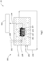
FIGS. 1-3 illustrate schematic views of apparatuses for measuring total organic carbon according to some embodiments of the present invention. - Unless defined otherwise, all the scientific or technical terms used herein should have the same meanings as commonly understood by one of ordinary skilled in the art to which the present invention belongs. The terms "first", "second" and the like used in the present invention do not mean any sequential order, number or importance, but are only used for distinguishing from one another. The terms "comprising", "including", "having", "containing" and the like used in the present invention mean that, in addition to the items listed thereafter and equivalents thereof, other items may also be encompassed therein.
- The approximate expression in the present invention is used to define the quantity, indicating that the present invention is not limited to the exact quantity, but encompass modifications that are close to the quality, acceptable and do not result in changes of corresponding basic functions thereof. Accordingly, defining a quantity by "about", "approximately" or the like means that the present invention is not limited to the exact numerical value. In some embodiments, approximate expression may correspond to the precision of the instrument that measures numerical values.
- Unless explicitly indicated otherwise, in the Description and claims, the singular or plural form of all items is not limited. Unless explicitly stated otherwise, the term "or" does not mean exclusion, but means there is at least one of the mentioned items (such as composition), including situations that there may be combinations of the mentioned items.
- Reference to "some embodiments" in the Description of the present invention means that a particular element (e.g. a feature, a structure and/or a characteristic) related to the present invention is included in at least one embodiment of the Description and may or may not be present within other embodiments. Furthermore, it is to be understood that elements of the present invention may be combined in any suitable manner.
- Referring to
figures 1 ,2 , and3 , some embodiments of the present invention relates todevices first compartment aqueous stream carbon dioxide analysis stream second compartment aqueous stream carbon dioxide first compartment - In some embodiments, as shown in
figure 1 , thedevice 100 comprises aninner tube 110 defining therein afirst compartment 101 and anouter tube 111 nested outside theinner tube 110, thesecond compartment 105 being located between theinner tube 110 and theouter tube 111 and surrounding thefirst compartment 101. Thetube wall 107 of theinner tube 110 is a separator which separates the firstaqueous stream 102 from the secondaqueous stream 106 and allows thecarbon dioxide 103 to pass through. - The material, shape, and configuration for the inner tube and the outer tube may be the same or substantially different. In
figure 1 , both of theinner tube 110 and theouter tube 111 extends linearly. In some embodiments, both of the inner tube and the outer tube meander. In some embodiments, one of the inner tube and the outer tube is a straight tube and the other is a curved tube. In some embodiments, the inner tube and the outer tube may be straight in part and curved in part. - In some embodiments, the first compartment surrounds the second compartment. In some embodiments, the first compartment overlaps the second compartment in part.
- In some embodiments, as shown in
figure 2 , thedevice 200 comprises atube 210 which defines afirst compartment 201 therein and extends in a curved manner and acontainer 211 which contains thetube 210 therein and defines asecond compartment 205 therebetween. Thefirst compartment 201 is located within thetube 210 and is surrounded by thesecond compartment 205. Thetube wall 207 of thetube 210 is a separator which separates the firstaqueous stream 202 from the secondaqueous stream 206 and allows thecarbon dioxide 203 to pass through. - The
separators separators inner tube 110 and thetube 210 are Teflon ® tubes. - In some embodiments, as shown in
figure 3 , thedevice 300 comprises afirst container 310 and asecond container 311 which are separated by a certain distance from each other, define afirst compartment 301 and asecond compartment 305 therein respectively, and are connected together by aconduit 307. Theconduit 307 transports thedioxide 303 from thefirst compartment 301 to thesecond compartment 305. - The first
aqueous streams aqueous streams aqueous streams - In the
first compartments aqueous streams dioxides reactants first compartments dioxides reactants - Generation of
dioxides first compartments second compartments first compartments separators conduit 307 into thesecond compartments second compartments analysis streams aqueous streams - In some embodiments, the second
aqueous streams dioxides aqueous streams aqueous streams first compartments second compartments dioxides first compartments first compartments second compartments carbon dioxides - In some embodiments,
reactants second compartments dioxides reactants reactants - In some embodiments, the
devices first compartments second compartments - After removing the inorganic carbons with the device and method relating to the embodiments of the present invention, the total organic carbon of the
analysis streams apparatuses apparatuses devices organic carbon analyzers organic carbon analyzers - In some embodiments, the total
organic carbon analyzers analysis streams analysis streams organic carbon analyzers - The device and method for removing inorganic carbon relating to embodiments of the present invention utilize the pressure difference between the first compartment and the second compartment and have the carbon dioxide converted from the inorganic carbon of the first compartment be absorbed in the second compartment, so as to realize removal of the inorganic carbon. In some embodiments, the second aqueous stream facilitates absorption of the carbon dioxide. In some embodiments, the concentration of the volatile organic of the first compartment is the same as that of the second compartment, such that the volatile organics would have no substantial loss when removing the inorganics. The apparatus and method for measuring total organic carbon relating to embodiments of the present invention can measure the total organic carbon more precisely.
- The following experimental examples may provide references for a person with ordinary skills in the art in practicing the present invention. Extent of the claims are not limited by these examples.
- Chloroform solution with 400 ppb (parts per billion) of carbon is prepared by mixing 100% chloroform into water.
- A stream of the above prepared chloroform solution is introduced into a total organic carbon analyzer with a flow rate of 0.5 milliliter per minute without removing the inorganic carbon, where it is acidized by adding phosphoric acid with 6 mol per liter, oxidized with ultraviolet light, measured with a membrane conductivity detector, and the resultant total organic carbon value is 400 ppb, inorganic carbon value is 704 ppb, which are the measurement baseline values of the total organic carbon and inorganic carbon for the prepared chloroform solution.
- Another stream of the above prepared chloroform solution is added with phosphoric acid of 6 mol per liter and is purged of inorganic carbon by vacuuming, and is then introduced into the same total organic carbon analyzer as comparative example 1 with a flow rate of 0.5 milliliter per minute. The resultant total organic carbon value is 158 ppb, inorganic carbon value is 16 ppb. It can be seen that, in comparison with the measurement baseline values of comparative example 1, more than half of the organic carbon (volatile organics) are lost when purging inorganic carbon in the chloroform solution by vacuuming, and the measured total organic carbon is far less than the measurement baseline value.
- A Teflon ®AF curved tube is placed in a container (a glass beaker), so that the device for removing inorganic carbon as shown in
figure 2 is implemented. - A stream of the above prepared chloroform solution is introduced into the first compartment in the curved tube and the second compartment outside the curved tube and inside the container with a flow rate of 0.5 microlitre per minute. Phosphoric acid of 6 mol per liter is added into the first compartment, sodium hydroxide which provides the chloroform solution with pH>7 and ethylenediaminetetraacetic acid of 0.01 mol per litre are provided to the second compartment.
- The analysis stream from the first compartment is introduced into the same total organic carbon analyzer as comparative example 1 with a flow rate of 0.5 milliliter per minute. The resultant total organic carbon value is 375 ppb, inorganic carbon value is 327 ppb. It can be seen that, in comparison with the measurement baseline values of comparative example 1, while inorganic carbon in the chloroform solution is reduced by more than half, the reduction of the organic carbon is negligible, and the measured total organic carbon is more reliable and accurate.
- Although the present invention has been set forth in connection with specific embodiments, the person skilled in the art shall be understood that many modifications and variations may be made to the present invention. Therefore, it should be recognized that the intention of the claims is to cover all these modifications and variations within the real concept and range of the present invention.
Claims (10)
- A device for removing inorganic carbon, comprising:a first compartment for receiving a first aqueous stream having a first concentration of inorganic carbon and providing carbon dioxide converted from the inorganic carbon and an analysis stream having a second concentration of inorganic carbon, the second concentration being lower than the first concentration; anda second compartment for receiving a second aqueous stream and absorbing the carbon dioxide from the first compartment.
- The device of claim 1, wherein the first and the second compartments comprise a same concentration of volatile organic compound.
- The device of claim 1, comprising a separator for separating the first aqueous stream from the second aqueous stream and allowing the carbon dioxide to pass through.
- The device of claim 1, comprising a conduit for transporting the carbon dioxide from the first compartment to the second compartment.
- An apparatus for measuring total organic carbon, comprising:the device of any of claims 1-4; anda total organic carbon analyzer for receiving the analysis stream and measuring the total organic carbon of the analysis stream.
- A method for removing inorganic carbon, comprising:receiving in a first compartment a first aqueous stream having a first concentration of inorganic carbon and providing carbon dioxide converted from the inorganic carbon and an analysis stream having a second concentration of inorganic carbon, the second concentration being lower than the first concentration; andreceiving a second aqueous stream and absorbing in a second compartment the carbon dioxide from the first compartment.
- The method of claim 6, wherein the first and the second compartments comprise a same concentration of volatile organic compound.
- The method of claim 6, comprising: providing a reagent to the first compartment to convert the inorganic carbon to the carbon dioxide.
- The method of claim 6, comprising: providing a reagent to the second compartment to absorb the carbon dioxide.
- A method for measuring total organic carbon, comprising:the method for removing inorganic carbon of any of claims 6-9; andmeasuring the total organic carbon of the analysis stream using a total organic carbon analyzer.
Applications Claiming Priority (2)
| Application Number | Priority Date | Filing Date | Title |
|---|---|---|---|
| CN201410724329.2A CN105716927A (en) | 2014-12-03 | 2014-12-03 | Facility and method for removing inorganic carbon, and apparatus and method for detecting total organic carbon |
| PCT/CN2015/000844 WO2016086507A1 (en) | 2014-12-03 | 2015-12-03 | Device and method used for removing inorganic carbon, and apparatus and method used for detecting total organic carbon |
Publications (2)
| Publication Number | Publication Date |
|---|---|
| EP3229016A1 true EP3229016A1 (en) | 2017-10-11 |
| EP3229016A4 EP3229016A4 (en) | 2018-05-09 |
Family
ID=56090888
Family Applications (1)
| Application Number | Title | Priority Date | Filing Date |
|---|---|---|---|
| EP15865044.0A Withdrawn EP3229016A4 (en) | 2014-12-03 | 2015-12-03 | Device and method used for removing inorganic carbon, and apparatus and method used for detecting total organic carbon |
Country Status (5)
| Country | Link |
|---|---|
| EP (1) | EP3229016A4 (en) |
| JP (1) | JP2018501473A (en) |
| CN (1) | CN105716927A (en) |
| CA (1) | CA2969357A1 (en) |
| WO (1) | WO2016086507A1 (en) |
Families Citing this family (1)
| Publication number | Priority date | Publication date | Assignee | Title |
|---|---|---|---|---|
| CN112986453B (en) * | 2021-05-11 | 2021-07-20 | 中国科学院地质与地球物理研究所 | A method and system for high-resolution determination of organic carbon isotopes in stalagmites |
Family Cites Families (9)
| Publication number | Priority date | Publication date | Assignee | Title |
|---|---|---|---|---|
| US5820823A (en) * | 1990-03-02 | 1998-10-13 | Sievers Instruments, Inc. | Method and apparatus for the measurement of dissolved carbon |
| US5132094A (en) * | 1990-03-02 | 1992-07-21 | Sievers Instruments, Inc. | Method and apparatus for the determination of dissolved carbon in water |
| JP2822711B2 (en) * | 1991-07-29 | 1998-11-11 | 株式会社島津製作所 | Organic carbon measuring device |
| WO1997021096A1 (en) * | 1995-12-04 | 1997-06-12 | Sievers Instruments, Inc. | Method and apparatus for the measurement of dissolved carbon |
| JP4462099B2 (en) * | 2005-04-19 | 2010-05-12 | 株式会社島津製作所 | Total organic carbon measuring device |
| EP1890141A4 (en) * | 2005-05-26 | 2009-01-21 | Shimadzu Corp | Measuring method for total organic carbon, measuring method for total nitrogen and measuring apparatus for the methods |
| JP4983914B2 (en) * | 2007-03-20 | 2012-07-25 | 株式会社島津製作所 | Total organic carbon measuring device |
| CN102042981B (en) * | 2010-11-09 | 2012-01-11 | 厦门大学 | In-situ tester of dissolved inorganic carbon |
| CN203324080U (en) * | 2013-07-05 | 2013-12-04 | 苏州埃兰分析仪器有限公司 | Total inorganic carbon reaction gas cooling and dehydrating device |
-
2014
- 2014-12-03 CN CN201410724329.2A patent/CN105716927A/en active Pending
-
2015
- 2015-12-03 JP JP2017529034A patent/JP2018501473A/en active Pending
- 2015-12-03 CA CA2969357A patent/CA2969357A1/en not_active Abandoned
- 2015-12-03 WO PCT/CN2015/000844 patent/WO2016086507A1/en not_active Ceased
- 2015-12-03 EP EP15865044.0A patent/EP3229016A4/en not_active Withdrawn
Also Published As
| Publication number | Publication date |
|---|---|
| JP2018501473A (en) | 2018-01-18 |
| CA2969357A1 (en) | 2016-06-09 |
| WO2016086507A1 (en) | 2016-06-09 |
| CN105716927A (en) | 2016-06-29 |
| EP3229016A4 (en) | 2018-05-09 |
Similar Documents
| Publication | Publication Date | Title |
|---|---|---|
| US20210208116A1 (en) | Instrument and method for simultaneously testing molecular weight distribution and organic nitrogen level of water sample | |
| JP2009264913A (en) | Underwater total alkalinity measuring method | |
| US20160223509A1 (en) | Method and device for analysing sulfates in a liquid | |
| CN204128953U (en) | Auto injection gas phase molecular absorption spectrometer | |
| CN105067542A (en) | Ship-borne pH and pCO2 measuring device and measuring method based on photometric method | |
| Lin et al. | A portable and 3D printing microplasma-based device coupling with visual colorimetry for field speciation analysis of SO32−/S2− in environmental water sample | |
| CN102042925A (en) | Method and apparatus for removing chloride from samples containing volatile organic carbon | |
| EP3229016A1 (en) | Device and method used for removing inorganic carbon, and apparatus and method used for detecting total organic carbon | |
| CN104792704B (en) | Tri- index continuous synchronization real-time online determining instrument of TOC, TN, TP | |
| JP2017040538A (en) | Reaction vessel unit, gasification device, pre-treatment device, and mercury measurement instrument | |
| CN116148243A (en) | A kind of detection method of total amount of inorganic carbon in organic decarburization solution | |
| WO2020116274A1 (en) | Method and device for isolating and analyzing target substance in solution | |
| Zhao et al. | An environment-friendly device for rapid determination of chemical oxygen demand in waters based on ozone-induced chemiluminescence technology | |
| CN102753951A (en) | Online titration in an interchangeable instrument | |
| JP2012093156A (en) | Exhaust gas collection device and ammonia collection method using the same | |
| Inglett et al. | Denitrification measurement using membrane inlet mass spectrometry | |
| CN111458319A (en) | Device and method for online determination of ammonia nitrogen concentration in water body | |
| JP7234202B2 (en) | Apparatus and method for continuous analysis of dissolved inorganic carbon (DIC) concentration and its isotopic carbon and oxygen composition | |
| CN109253984A (en) | Water sample total organic carbon content analysis equipment and analysis method thereof | |
| CN207689371U (en) | Ultralow memory effect atomic fluorescence trace mercury vapourmeter is miniaturized | |
| JP7520430B2 (en) | Reduction materials | |
| CA2960530C (en) | On-line wet chemistry analyzer | |
| CN109187519B (en) | Hydrogen fluoride gas quantitative analysis device and analysis method | |
| CN110376327A (en) | A kind of method of content of fluoride in ion chromatography flue gas | |
| CN217247147U (en) | Environmental monitoring laboratory water sample pretreatment device |
Legal Events
| Date | Code | Title | Description |
|---|---|---|---|
| PUAI | Public reference made under article 153(3) epc to a published international application that has entered the european phase |
Free format text: ORIGINAL CODE: 0009012 |
|
| 17P | Request for examination filed |
Effective date: 20170703 |
|
| AK | Designated contracting states |
Kind code of ref document: A1 Designated state(s): AL AT BE BG CH CY CZ DE DK EE ES FI FR GB GR HR HU IE IS IT LI LT LU LV MC MK MT NL NO PL PT RO RS SE SI SK SM TR |
|
| AX | Request for extension of the european patent |
Extension state: BA ME |
|
| DAV | Request for validation of the european patent (deleted) | ||
| DAX | Request for extension of the european patent (deleted) | ||
| A4 | Supplementary search report drawn up and despatched |
Effective date: 20180409 |
|
| RIC1 | Information provided on ipc code assigned before grant |
Ipc: G01N 33/18 20060101AFI20180403BHEP |
|
| STAA | Information on the status of an ep patent application or granted ep patent |
Free format text: STATUS: THE APPLICATION IS DEEMED TO BE WITHDRAWN |
|
| 18D | Application deemed to be withdrawn |
Effective date: 20181113 |