EP3228957A1 - Air conditioner - Google Patents
Air conditioner Download PDFInfo
- Publication number
- EP3228957A1 EP3228957A1 EP15864716.4A EP15864716A EP3228957A1 EP 3228957 A1 EP3228957 A1 EP 3228957A1 EP 15864716 A EP15864716 A EP 15864716A EP 3228957 A1 EP3228957 A1 EP 3228957A1
- Authority
- EP
- European Patent Office
- Prior art keywords
- air
- refrigerant gas
- indoor unit
- air conditioner
- refrigerant
- Prior art date
- Legal status (The legal status is an assumption and is not a legal conclusion. Google has not performed a legal analysis and makes no representation as to the accuracy of the status listed.)
- Granted
Links
Images




Classifications
-
- F—MECHANICAL ENGINEERING; LIGHTING; HEATING; WEAPONS; BLASTING
- F24—HEATING; RANGES; VENTILATING
- F24F—AIR-CONDITIONING; AIR-HUMIDIFICATION; VENTILATION; USE OF AIR CURRENTS FOR SCREENING
- F24F11/00—Control or safety arrangements
- F24F11/70—Control systems characterised by their outputs; Constructional details thereof
- F24F11/72—Control systems characterised by their outputs; Constructional details thereof for controlling the supply of treated air, e.g. its pressure
- F24F11/74—Control systems characterised by their outputs; Constructional details thereof for controlling the supply of treated air, e.g. its pressure for controlling air flow rate or air velocity
- F24F11/77—Control systems characterised by their outputs; Constructional details thereof for controlling the supply of treated air, e.g. its pressure for controlling air flow rate or air velocity by controlling the speed of ventilators
-
- F—MECHANICAL ENGINEERING; LIGHTING; HEATING; WEAPONS; BLASTING
- F24—HEATING; RANGES; VENTILATING
- F24F—AIR-CONDITIONING; AIR-HUMIDIFICATION; VENTILATION; USE OF AIR CURRENTS FOR SCREENING
- F24F1/00—Room units for air-conditioning, e.g. separate or self-contained units or units receiving primary air from a central station
- F24F1/0007—Indoor units, e.g. fan coil units
- F24F1/0011—Indoor units, e.g. fan coil units characterised by air outlets
- F24F1/0014—Indoor units, e.g. fan coil units characterised by air outlets having two or more outlet openings
-
- F—MECHANICAL ENGINEERING; LIGHTING; HEATING; WEAPONS; BLASTING
- F24—HEATING; RANGES; VENTILATING
- F24F—AIR-CONDITIONING; AIR-HUMIDIFICATION; VENTILATION; USE OF AIR CURRENTS FOR SCREENING
- F24F11/00—Control or safety arrangements
- F24F11/30—Control or safety arrangements for purposes related to the operation of the system, e.g. for safety or monitoring
- F24F11/32—Responding to malfunctions or emergencies
- F24F11/36—Responding to malfunctions or emergencies to leakage of heat-exchange fluid
-
- F—MECHANICAL ENGINEERING; LIGHTING; HEATING; WEAPONS; BLASTING
- F24—HEATING; RANGES; VENTILATING
- F24F—AIR-CONDITIONING; AIR-HUMIDIFICATION; VENTILATION; USE OF AIR CURRENTS FOR SCREENING
- F24F11/00—Control or safety arrangements
- F24F11/70—Control systems characterised by their outputs; Constructional details thereof
- F24F11/72—Control systems characterised by their outputs; Constructional details thereof for controlling the supply of treated air, e.g. its pressure
- F24F11/74—Control systems characterised by their outputs; Constructional details thereof for controlling the supply of treated air, e.g. its pressure for controlling air flow rate or air velocity
-
- F—MECHANICAL ENGINEERING; LIGHTING; HEATING; WEAPONS; BLASTING
- F24—HEATING; RANGES; VENTILATING
- F24F—AIR-CONDITIONING; AIR-HUMIDIFICATION; VENTILATION; USE OF AIR CURRENTS FOR SCREENING
- F24F11/00—Control or safety arrangements
- F24F11/89—Arrangement or mounting of control or safety devices
-
- F—MECHANICAL ENGINEERING; LIGHTING; HEATING; WEAPONS; BLASTING
- F25—REFRIGERATION OR COOLING; COMBINED HEATING AND REFRIGERATION SYSTEMS; HEAT PUMP SYSTEMS; MANUFACTURE OR STORAGE OF ICE; LIQUEFACTION SOLIDIFICATION OF GASES
- F25B—REFRIGERATION MACHINES, PLANTS OR SYSTEMS; COMBINED HEATING AND REFRIGERATION SYSTEMS; HEAT PUMP SYSTEMS
- F25B1/00—Compression machines, plants or systems with non-reversible cycle
-
- F—MECHANICAL ENGINEERING; LIGHTING; HEATING; WEAPONS; BLASTING
- F25—REFRIGERATION OR COOLING; COMBINED HEATING AND REFRIGERATION SYSTEMS; HEAT PUMP SYSTEMS; MANUFACTURE OR STORAGE OF ICE; LIQUEFACTION SOLIDIFICATION OF GASES
- F25B—REFRIGERATION MACHINES, PLANTS OR SYSTEMS; COMBINED HEATING AND REFRIGERATION SYSTEMS; HEAT PUMP SYSTEMS
- F25B49/00—Arrangement or mounting of control or safety devices
- F25B49/02—Arrangement or mounting of control or safety devices for compression type machines, plants or systems
-
- F—MECHANICAL ENGINEERING; LIGHTING; HEATING; WEAPONS; BLASTING
- F24—HEATING; RANGES; VENTILATING
- F24F—AIR-CONDITIONING; AIR-HUMIDIFICATION; VENTILATION; USE OF AIR CURRENTS FOR SCREENING
- F24F1/00—Room units for air-conditioning, e.g. separate or self-contained units or units receiving primary air from a central station
- F24F1/0003—Room units for air-conditioning, e.g. separate or self-contained units or units receiving primary air from a central station characterised by a split arrangement, wherein parts of the air-conditioning system, e.g. evaporator and condenser, are in separately located units
-
- Y—GENERAL TAGGING OF NEW TECHNOLOGICAL DEVELOPMENTS; GENERAL TAGGING OF CROSS-SECTIONAL TECHNOLOGIES SPANNING OVER SEVERAL SECTIONS OF THE IPC; TECHNICAL SUBJECTS COVERED BY FORMER USPC CROSS-REFERENCE ART COLLECTIONS [XRACs] AND DIGESTS
- Y02—TECHNOLOGIES OR APPLICATIONS FOR MITIGATION OR ADAPTATION AGAINST CLIMATE CHANGE
- Y02B—CLIMATE CHANGE MITIGATION TECHNOLOGIES RELATED TO BUILDINGS, e.g. HOUSING, HOUSE APPLIANCES OR RELATED END-USER APPLICATIONS
- Y02B30/00—Energy efficient heating, ventilation or air conditioning [HVAC]
- Y02B30/70—Efficient control or regulation technologies, e.g. for control of refrigerant flow, motor or heating
Definitions
- the present invention relates to an air conditioner in which, for example, a flammable refrigerant is used.
- Patent Literature 1 Japanese Unexamined Patent Publication No. 13348/2012 (Tokukai 2012-13348)
- the air volume from the outlet at a time of detecting the refrigerant gas by the refrigerant gas sensor is determined; however, even if the air conditioner is configured to blow a wind from the outlet of its indoor unit, that air speed of the wind from the outlet of the indoor unit may fall short for sufficiently restraining the local accumulation of the refrigerant gas in an area of the indoor space, if the air conditioner is installed in a large room, for example.
- an object of the present invention to provide an air conditioner capable of sufficiently preventing local accumulation of a refrigerant gas leaked in an indoor unit in an area of an indoor space.
- a first aspect of the present invention is an air conditioner, including an indoor unit having one or more outlets and an outdoor unit connected to the indoor unit, in which a flammable refrigerant or a mildly flammable refrigerant is used.
- the air conditioner includes a refrigerant gas sensor provided in the indoor unit, and when the refrigerant gas sensor detects refrigerant gas, a control is performed such that air is blown from the one or more outlets at a minimum air speed or higher, the minimum air speed being preset in accordance with a rated cooling capacity of the air conditioner.
- a second aspect of the present invention is the air conditioner of the first aspect, adapted so that the flammable refrigerant or the mildly flammable refrigerant is R32, a mixed refrigerant containing 65wt% or more of R32, or HFO based mixed refrigerant.
- a third aspect of the present invention is the air conditioner of the first or the second aspect, adapted so that an air blowout mode from the one or more outlets of the indoor unit, at a time of detecting the refrigerant gas by the refrigerant gas sensor, is at least one of an upper outblow, a lower outblow, an upper/lower outblow, and a left/right outblow.
- a fourth aspect of the present invention is the air conditioner of the third aspect, adapted so that the indoor unit is capable of taking at least two of the upper outblow, the lower outblow, the upper/lower outblow, and the left/right outblow, as the air blowout mode from the one or more outlets at the minimum air speed at a time of detecting the refrigerant gas by the refrigerant gas sensor, and the minimum air speed is determined in advance for each of the air blowout modes from the one or more outlets.
- the minimum air speed at the one or more outlets when the refrigerant gas sensor detects the refrigerant gas is determined beforehand for each of the air blowout modes from the one or more outlets. Therefore, when there is a leakage of the refrigerant gas in the indoor unit, it is possible to effectively prevent local accumulation of the refrigerant gas in an area within the indoor space.
- a fifth aspect of the present invention is the air conditioner of any one of the first to fourth aspects, adapted so that the indoor unit is an on-floor type indoor unit.
- This air conditioner includes the on-floor type indoor unit capable of preventing local accumulation of the refrigerant gas in an area nearby the floor of the indoor space.
- the present invention brings about the following advantageous effects.
- the refrigerant gas sensor detects the refrigerant gas
- air is blown out from the one or more outlets at a minimum air speed or higher, the minimum air speed being preset according to the rated cooling capacity of the air conditioner. Therefore, when there is a leakage of the refrigerant gas in the indoor unit, it is possible to sufficiently prevent local accumulation of the refrigerant gas in an area within the indoor space.
- an air conditioner of the present embodiment includes: a compressor 1; a four-pass switching valve 2 whose one end is connected to a discharge side of the compressor 1; an outdoor heat exchanger 3 whose one end is connected to another end of the four-pass switching valve 2; an electric expansion valve 4 whose one end is connected to another end of the outdoor heat exchanger 3; an indoor heat exchanger 5 whose one end is connected to another end of the electric expansion valve 4 via a stop valve 12 and a communication pipe L1; and an accumulator 6 whose one end is connected to another end of the indoor heat exchanger 5 via a stop valve 13, a communication pipe L2, and the four-pass switching valve 2, and whose another end is connected to the sucking side of the compressor 1.
- the above mentioned compressor 1, the four-pass switching valve 2, the outdoor heat exchanger 3, the electric expansion valve 4, the indoor heat exchanger 5, and the accumulator 6 constitute a refrigerant circuit.
- This air conditioner further includes an outdoor fan 7 disposed nearby the outdoor heat exchanger 3, and an indoor fan 8 disposed nearby the indoor heat exchanger 5.
- the above mentioned compressor 1, the four-pass switching valve 2, the outdoor heat exchanger 3, the electric expansion valve 4, the accumulator 6, and the outdoor fan 7 are disposed in the outdoor unit 10, while the indoor heat exchanger 5 and the indoor fan 8 are disposed in the indoor unit 20.
- the compressor 1 is activated while switching the four-pass switching valve 2 to a switching position indicated by the solid lines. This causes the high-pressure refrigerant ejected from the compressor 1 to flow into the indoor heat exchanger 5, via the four-pass switching valve 2.
- the refrigerant condensed in the indoor heat exchanger 5 is decompressed in the electric expansion valve 4, and then flows into the outdoor heat exchanger 3.
- the refrigerant evaporated in the outdoor heat exchanger 3 returns to the sucking side of the compressor 1 via the four-pass switching valve 2 and the accumulator 6.
- the refrigerant circulates the refrigerant circuit constituted by the compressor 1, the indoor heat exchanger 5, the electric expansion valve 4, the outdoor heat exchanger 3, and the accumulator 6, thereby carrying out a refrigerating cycle. Then, circulation of the room air by the indoor fan 8 through the indoor heat exchanger 5 warms up the room.
- the compressor 1 is activated while switching the four-pass switching valve 2 to a switching position indicated by the dotted lines.
- This causes the high-pressure refrigerant ejected from the compressor 1 to flow into the outdoor heat exchanger 3, via the four-pass switching valve 2.
- the refrigerant condensed in the outdoor heat exchanger 3 is decompressed in the electric expansion valve 4, and then flows into the indoor heat exchanger 5.
- the refrigerant evaporated in the indoor heat exchanger 5 returns to the sucking side of the compressor 1 via the four-pass switching valve 2 and the accumulator 6.
- the "flammable refrigerant” encompasses a flammable refrigerant as well as a mildly flammable refrigerant.
- the air conditioner adopts, for example, an R32 which is a mildly flammable refrigerant, a mixed refrigerant containing 65wt% or more of the R32, or an HFO (hydrofluoroolefin) based mixed refrigerant; however, it is possible to adopt for example an R290. Further, in this air conditioner is used a refrigerant whose specific weight is heavier than the air.
- the indoor unit 20 is an on-floor type indoor unit, and includes: a bottom frame 21 in substantially a rectangular parallelpiped shape, whose rear surface side is to be attached to a wall surface of the room; a front grill 22 attached to the front surface side of the bottom frame 21, which has, on its front surface, an opening part 22d in substantially a parallel piped shape; and a front panel 23 attached so as to cover the opening part 22d of the front grill 22.
- the bottom frame 21, the front grill 22, and the front panel 23 form a casing 20a.
- an upper outlet 22a In an upper portion of the front grill 22 is provided an upper outlet 22a. In a lower portion of the front grill 22 is provided a lower outlet 22b.
- An upper outlet path P1 in communication with the upper outlet 22a is provided with a vertical flap 24 configured to change the wind direction of the air flow from the upper outlet 22a relative to a vertical direction; and a horizontal flap 25 configured to change the wind direction of the air flow from the upper outlet 22a relative to a horizontal direction.
- the vertical flap 24 is connected to a flap motor 24a (see FIG. 6 ), and the horizontal flap 25 is connected to a flap motor 25a (see FIG. 6 ).
- the vertical flap 24, driven by the flap motor 24a is capable of rotating about a rotational axis extending in a horizontal direction.
- the vertical flap 24 rotates within a vertical wind direction control range shown in FIG. 4 , and blows out cool or warm air forward and obliquely upward from the upper outlet 22a.
- the upper outlet 22a is closed as shown in FIG. 2 , while the operation is stopped.
- the horizontal flap 25, driven by the flap motor 25a, is capable of swinging in horizontal directions.
- the horizontal flap 25 swings within a horizontal wind direction control range, and changes the direction in which cool or warm air is blown out from the upper outlet 22a.
- the indoor unit 20 of the air conditioner of the present embodiment is configured so that the horizontal wind direction of the upper outlet 22a is switched amongst a frontward direction, a left direction, a right direction, and the horizontal directions.
- a shutter 30 which opens and closes the lower outlet 22b, and the horizontal flap 31 which changes the wind direction of the air flow from the lower outlet path 22b, in relation to the horizontal direction.
- the shutter 30 is connected to a shutter motor 30b.
- This shutter 30 stopping at a position A indicated by a dashed line opens the lower outlet 22b, and closes the lower outlet 22b when stopped at a position B indicated by a dashed line.
- the horizontal flap 31 is a flap whose direction is manually adjusted.
- the indoor unit 20 of the air conditioner of the present embodiment is configured so that the horizontal wind direction of the lower outlet 22b is switched amongst a frontward direction, a left direction, a right direction, and the left/right directions (swing in left and right directions).
- a side outlet 22c On each of the side faces on the left and right of the front panel 23 is provided a side outlet 22c ( FIG. 2 only illustrates the right side). In each of side outlet paths in communication with the side outlets 22c is disposed a shutter (not shown) which opens and closes the side outlet 22c on the corresponding side.
- a shutter On the upper side of the front panel 23 is provided an upper inlet port 23a.
- a lower inlet port 23b On the lower side of the front panel 23 is provided a lower inlet port 23b.
- a fan motor 26 is fixed.
- the indoor fan 8 to which the shaft of the fan motor 26 is connected is disposed on the bottom frame 21 so that its axis is directed in the front-back directions.
- the indoor fan 8 is a turbofan which blows out the air, which is sucked from the front surface side, to radially outward with respect to the axis.
- the bottom frame 21 has a bell-mouth 27 formed on the front surface side of the indoor fan 8.
- On the front surface side of the bell-mouth 27 is disposed the indoor heat exchanger 5.
- On the front surface side of the indoor heat exchanger 5 is attached the front grill 22. Further on the front surface side of the front grill 22 is attached the front panel 23. In the openings 22c of the front grill 22 are attached filters.
- the fan motor 26 when an operation starts, the fan motor 26 is driven, thus rotating the indoor fan 8. With the rotation of the indoor fan 8, the room air is sucked into the indoor unit 20 via the upper inlet port 23a and the lower inlet port 23b.
- the room air sucked into the indoor unit 20 is subjected to heat exchanging by the indoor heat exchanger 5, and then blown out from at least one of the upper outlet 22a, the lower outlet 22c and the side outlets 22c.
- the shutter 30 in the lower outlet path P2 opens and closes the lower outlet 22b, and the shutters in the side outlet paths open and close the side outlets 22c.
- a drain pan 28 which receives and drains condensed water from the air, which is generated by the indoor heat exchanger 5.
- an electronic component box 50 is disposed on the right outer side (outer side relative to the length), and the above of the indoor heat exchanger 5.
- a refrigerant gas sensor 9 is attached below the electronic component box 50 in a detachable manner. This refrigerant gas sensor 9 disposed on the right outer side (outer side relative to the length) of the indoor heat exchanger 5 and the drain pan 28.
- the refrigerant gas leaks due to, for example, a damage to the refrigerant pipe of the indoor heat exchanger 5, the refrigerant gas whose specific weight is heavier than the air flows downward, and reaches the drain pan 28.
- the refrigerant gas having reached the drain pan 28 flows from the left end side to the right end side of the drain pan 28.
- the refrigerant gas having reached the drain pan 28 then easily overflows from the side of the drain pan 28 close to the refrigerant gas sensor 9 relative to the length.
- the refrigerant gas overflown accumulates at the bottom of the indoor unit 20, and leaks to the outside from the indoor unit 20.
- the electronic component box 50 accommodates therein the controlling unit 51, and controls the constituting members necessary for cooling and warming operations and the like of the air conditioner.
- the controlling unit 51 is connected to the fan motor 26, the refrigerant gas sensor 9, the flap motor 24a, the flap motor 25a, and the shutter motor 30b.
- the controlling unit 51 controls the indoor fan 8, the vertical flap 24, and the shutter 30, and determines if there is leakage of the refrigerant gas based on the detection result of the refrigerant gas by the refrigerant gas sensor 9.
- the refrigerant gas sensor 9 is a sensor for detecting leaked refrigerant gas, and is disposed at the same level as or lower than the drain pan 28, as shown in FIG. 5 . Further, the sensor is disposed on the right outer side (outer side relative to the length) of the drain pan 28, and on a rear side (back side) of the drain pan 28 and the indoor heat exchanger 5.
- the indoor unit 20 of the air conditioner of the present embodiment takes any of the upper outblow, the lower outblow, the upper/lower outblow, and the left/right outblow as the air blowout mode from the one or more outlets.
- FIG. 7A to 7C show the air blowout modes from the one or more outlets.
- On the left side is a side view of the indoor unit to illustrate upper and lower wind directions.
- On the right side is a top view of the indoor unit illustrating the horizontal wind directions.
- the direction of airflow from the upper outlet 22a is 20 to 70 degrees upward from a horizontal direction, whereas the direction of the airflow from the lower outlet 22b is substantially horizontal.
- FIG. 7D shows the air blowout mode from the outlets.
- On the left side is a front view of the indoor unit to illustrate the horizontal wind directions.
- On the right side is a top view of the indoor unit illustrating the horizontal wind directions.
- An indoor air volume is derived based on the rotation number of the indoor fan. Therefore, by dividing the air volume by the area of outlet (outlet area), the air speed (m/sec) of the wind from the outlet is calculated.
- the area of the outlet is an area of the upper outlet 22a for the upper outblow, the area of the lower outlet 22b for the lower outblow, the total area of the upper outlet 22a and the lower outlet 22b for the upper/lower outblow, and the total area of the side outlets 22c for the left/right outblow.
- Whether or not the air in the indoor space with the indoor unit 20 is sufficiently agitated is determined based on whether or not a flammable area which is local accumulation of the refrigerant gas is generated in the indoor space.
- the flammable area is an area with the refrigerant concentration of 5% or higher, when the refrigerant is "R290"; or an area with the refrigerant concentration of 10% to 30% when the refrigerant is "R32” or a "refrigerant containing 65% or more of R32".
- the evaluation was conducted with the ventilation conditions of the indoor space including a height of 2.4 m up to the ceiling, a door width of 900 mm, a gap of 3 mm at the top of the door or a gap of 3 mm at the bottom of the door, and a refrigerant gas leaking speed of 10 to 20 kg/hr.
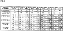
- FIG. 8 shows evaluation results for each state, on whether or not the air in the indoor space with the indoor unit 20 is sufficiently agitated.
- the circle indicates that the air in the indoor space was sufficiently agitated, while the cross indicates the air in the indoor space was not sufficiently agitated.
- the evaluation results in FIG. 8 the following details, taking as an example, the case where the indoor area equals to 18 tatami mats, the rated cooling capacity (kW) of the air conditioner is 5.6kW, and the air blowout mode of the wind from the outlets is the upper outblow. The indoor space was not sufficiently agitated when the air speed of the wind from the upper outlet 22a was 2.5 m/sec.
- the minimum value of the air speed (minimum air speed) for sufficient agitation of the air in the indoor space is 0.8 m/sec, which is the result of the case where the indoor area is 6 tatami mats, the rated cooling capacity (kW) of the air conditioner is 2.2 kW, and the air blowout mode from the one or more outlets is the left/right outblow.
- an air conditioner of the present invention is a model for an indoor area of 18 tatami mats (with the rated cooling capacity being 5.6 kW), and suppose a refrigerant gas is detected by the refrigerant gas sensor 9.
- the air speed of the wind from the upper outlet 22a is set to the minimum air speed of 3.0 m/sec or higher.
- the air speed of the wind from the lower outlet 22b is set to the minimum air speed of 2.7 m/sec or higher.
- the air speed of the wind from the upper outlet 22a and the lower outlet 22b is set to the minimum air speed of 2.5 m/sec or higher. If the air conditioner is in the mode of agitating the air in the indoor space by the left/right outblow, the air speed of the wind from the upper outlet 22a is set to the minimum air speed of 2.2 m/sec or higher.
- an air conditioner designed as a model commonly usable for indoor areas of 10 tatami mats, 12 tatami mats, 14 tatami mats, 16 tatami mats, and 18 tatami mats
- the compressor frequency may be changed to change the rated cooling capacity (kW) of the air conditioner according to the indoor area. More specifically, for example, for each of models, different frequencies are determined as the compressor frequency corresponding to the rated cooling capacity (kW).
- the air volume of the wind from the outlet, at a time of detecting the refrigerant gas by the refrigerant gas sensor 9, may be set constant.
- the air speed of the wind from the upper outlet 22a and the lower outlet 22b may be set to 2.5 m/sec or higher, which is the minimum air speed for a case of upper/lower outblow in the indoor area of 18 tatami mats (the rated cooling capacity of the air conditioner is 5.6 kW). This way, the air speed will be the minimum air speed or higher for the upper/lower outblow, even if the air conditioner is used as the model for 10 tatami mats, 12 tatami mats, 14 tatami mats, and 16 tatami mats.
- such an air conditioner requires an air speed of 2.5 m/sec of the wind from the outlets, for cases of detecting the refrigerant gas by the refrigerant gas sensor 9.
- the air speed higher than the minimum air speed is preferable.
- An example is to set the air speed of the wind from the outlets for cases of detecting the refrigerant gas by the refrigerant gas sensor 9 to approximately 4.4 m/sec, when the minimum air speed is 2.5 m/sec.
- the air conditioner of the present embodiment has the following characteristics.
- the refrigerant gas sensor 9 detects the refrigerant gas
- air is blown out from the one or more outlets at a minimum air speed or higher, the minimum air speed being preset according to the rated cooling capacity of the air conditioner. Therefore, when there is a leakage of the refrigerant gas in the indoor unit 20, it is possible to sufficiently prevent local accumulation of the refrigerant gas in an area within the indoor space.
- the minimum air speed at the one or more outlets when the refrigerant gas sensor 9 detects the refrigerant gas is determined beforehand for each of the air blowout modes from the one or more outlets. Therefore, when there is a leakage of the refrigerant gas in the indoor unit 20, it is possible to effectively prevent local accumulation of the refrigerant gas in an area within the indoor space.
- the above described embodiment deals with an indoor unit which is capable of taking any of the upper outblow, the lower outblow, the upper/lower outblow, and the left/right outblow as the air blowout mode from the one or more outlets, when the refrigerant gas is detected by the refrigerant gas sensor.
- the effects of the present invention are brought about, with an indoor unit which takes at least one of the upper outblow, the lower outblow, the upper/lower outblow, and the left/right outblow.
- the indoor unit may be an indoor unit having only an upper outlet, an indoor unit having only a lower outlet, an indoor unit having only an upper outlet and a lower outlet, or an indoor unit having only side outlets.
- Use of the present invention enables prevention of local accumulation of a leaked refrigerant gas in a certain area in an indoor space.
Landscapes
- Engineering & Computer Science (AREA)
- Mechanical Engineering (AREA)
- General Engineering & Computer Science (AREA)
- Chemical & Material Sciences (AREA)
- Combustion & Propulsion (AREA)
- Physics & Mathematics (AREA)
- Thermal Sciences (AREA)
- Fluid Mechanics (AREA)
- Air Conditioning Control Device (AREA)
Abstract
Description
- The present invention relates to an air conditioner in which, for example, a flammable refrigerant is used.
- As an air conditioner using a flammable refrigerant, there has traditionally been known an air conditioner whose indoor unit has a refrigerant gas sensor attached thereto.
- Patent Literature 1: Japanese Unexamined Patent Publication No.
13348/2012 (Tokukai 2012-13348) - In cases where a refrigerant gas leaks in an indoor unit of a traditional air conditioner, that leaked refrigerant gas locally accumulates in an area within the indoor space. Given this, there is an air conditioner which blows a wind from an outlet of its indoor unit, when a refrigerant gas sensor detects the refrigerant gas while the indoor unit is not in operation, thereby restraining the leaked refrigerant gas from locally accumulating in an area within the indoor space. In such a traditional air conditioner, the air volume from the outlet at a time of detecting the refrigerant gas by the refrigerant gas sensor is determined; however, even if the air conditioner is configured to blow a wind from the outlet of its indoor unit, that air speed of the wind from the outlet of the indoor unit may fall short for sufficiently restraining the local accumulation of the refrigerant gas in an area of the indoor space, if the air conditioner is installed in a large room, for example.
- In view of the above problem, it is an object of the present invention to provide an air conditioner capable of sufficiently preventing local accumulation of a refrigerant gas leaked in an indoor unit in an area of an indoor space.
- A first aspect of the present invention is an air conditioner, including an indoor unit having one or more outlets and an outdoor unit connected to the indoor unit, in which a flammable refrigerant or a mildly flammable refrigerant is used. The air conditioner includes a refrigerant gas sensor provided in the indoor unit, and when the refrigerant gas sensor detects refrigerant gas, a control is performed such that air is blown from the one or more outlets at a minimum air speed or higher, the minimum air speed being preset in accordance with a rated cooling capacity of the air conditioner.
- In this air conditioner, when the refrigerant gas sensor detects the refrigerant gas, air is blown out from the one or more outlets at a minimum air speed or higher, the minimum air speed being preset according to the rated cooling capacity of the air conditioner. Therefore, when there is a leakage of the refrigerant gas in the indoor unit, it is possible to sufficiently prevent local accumulation of the refrigerant gas in an area within the indoor space.
- A second aspect of the present invention is the air conditioner of the first aspect, adapted so that the flammable refrigerant or the mildly flammable refrigerant is R32, a mixed refrigerant containing 65wt% or more of R32, or HFO based mixed refrigerant.
- A third aspect of the present invention is the air conditioner of the first or the second aspect, adapted so that an air blowout mode from the one or more outlets of the indoor unit, at a time of detecting the refrigerant gas by the refrigerant gas sensor, is at least one of an upper outblow, a lower outblow, an upper/lower outblow, and a left/right outblow.
- A fourth aspect of the present invention is the air conditioner of the third aspect, adapted so that the indoor unit is capable of taking at least two of the upper outblow, the lower outblow, the upper/lower outblow, and the left/right outblow, as the air blowout mode from the one or more outlets at the minimum air speed at a time of detecting the refrigerant gas by the refrigerant gas sensor, and the minimum air speed is determined in advance for each of the air blowout modes from the one or more outlets.
- In this air conditioner, the minimum air speed at the one or more outlets when the refrigerant gas sensor detects the refrigerant gas is determined beforehand for each of the air blowout modes from the one or more outlets. Therefore, when there is a leakage of the refrigerant gas in the indoor unit, it is possible to effectively prevent local accumulation of the refrigerant gas in an area within the indoor space.
- A fifth aspect of the present invention is the air conditioner of any one of the first to fourth aspects, adapted so that the indoor unit is an on-floor type indoor unit.
- This air conditioner includes the on-floor type indoor unit capable of preventing local accumulation of the refrigerant gas in an area nearby the floor of the indoor space. Advantageous Effects of Invention
- As described above, the present invention brings about the following advantageous effects.
- In the first to fifth aspects of the present invention, when the refrigerant gas sensor detects the refrigerant gas, air is blown out from the one or more outlets at a minimum air speed or higher, the minimum air speed being preset according to the rated cooling capacity of the air conditioner. Therefore, when there is a leakage of the refrigerant gas in the indoor unit, it is possible to sufficiently prevent local accumulation of the refrigerant gas in an area within the indoor space.
-
- [
FIG. 1] FIG. 1 is a circuit diagram showing a refrigerant circuit of an air conditioner of an embodiment of the present invention. - [
FIG. 2] FIG. 2 is a perspective view of the indoor unit ofFIG. 1 . - [
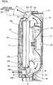
FIG. 3] FIG. 3 is a front view of the indoor unit. - [
FIG. 4] FIG. 4 is a cross sectional view taken at the IV-IV line inFIG. 3 . - [
FIG. 5] FIG. 5 is a perspective view of the indoor unit from which a front panel is detached. - [
FIG. 6] FIG. 6 is a block diagram of a control block of the indoor unit. - [
FIG. 7] FIG. 7A to 7D are an explanatory diagram for wind direction of the wind blown out from the outlet, when the refrigerant gas sensor detects a refrigerant gas. - [
FIG. 8] FIG. 8 is a diagram showing an evaluation result of whether or not the air in the indoor space is agitated, when the refrigerant gas is leaked. - The following describes embodiments of an air conditioner related to the present invention, with reference to the drawings.
- As shown in
FIG. 1 , an air conditioner of the present embodiment includes: acompressor 1; a four-pass switching valve 2 whose one end is connected to a discharge side of thecompressor 1; anoutdoor heat exchanger 3 whose one end is connected to another end of the four-pass switching valve 2; anelectric expansion valve 4 whose one end is connected to another end of theoutdoor heat exchanger 3; anindoor heat exchanger 5 whose one end is connected to another end of theelectric expansion valve 4 via astop valve 12 and a communication pipe L1; and anaccumulator 6 whose one end is connected to another end of theindoor heat exchanger 5 via astop valve 13, a communication pipe L2, and the four-pass switching valve 2, and whose another end is connected to the sucking side of thecompressor 1. The above mentionedcompressor 1, the four-pass switching valve 2, theoutdoor heat exchanger 3, theelectric expansion valve 4, theindoor heat exchanger 5, and theaccumulator 6 constitute a refrigerant circuit. - This air conditioner further includes an
outdoor fan 7 disposed nearby theoutdoor heat exchanger 3, and anindoor fan 8 disposed nearby theindoor heat exchanger 5. The above mentionedcompressor 1, the four-pass switching valve 2, theoutdoor heat exchanger 3, theelectric expansion valve 4, theaccumulator 6, and theoutdoor fan 7 are disposed in theoutdoor unit 10, while theindoor heat exchanger 5 and theindoor fan 8 are disposed in theindoor unit 20. - During a warming operation of the air conditioner, the
compressor 1 is activated while switching the four-pass switching valve 2 to a switching position indicated by the solid lines. This causes the high-pressure refrigerant ejected from thecompressor 1 to flow into theindoor heat exchanger 5, via the four-pass switching valve 2. The refrigerant condensed in theindoor heat exchanger 5 is decompressed in theelectric expansion valve 4, and then flows into theoutdoor heat exchanger 3. The refrigerant evaporated in theoutdoor heat exchanger 3 returns to the sucking side of thecompressor 1 via the four-pass switching valve 2 and theaccumulator 6. This way, the refrigerant circulates the refrigerant circuit constituted by thecompressor 1, theindoor heat exchanger 5, theelectric expansion valve 4, theoutdoor heat exchanger 3, and theaccumulator 6, thereby carrying out a refrigerating cycle. Then, circulation of the room air by theindoor fan 8 through theindoor heat exchanger 5 warms up the room. - To the contrary, during a cooling operation (including dehumidification operation), the
compressor 1 is activated while switching the four-pass switching valve 2 to a switching position indicated by the dotted lines. This causes the high-pressure refrigerant ejected from thecompressor 1 to flow into theoutdoor heat exchanger 3, via the four-pass switching valve 2. The refrigerant condensed in theoutdoor heat exchanger 3 is decompressed in theelectric expansion valve 4, and then flows into theindoor heat exchanger 5. The refrigerant evaporated in theindoor heat exchanger 5 returns to the sucking side of thecompressor 1 via the four-pass switching valve 2 and theaccumulator 6. This executes a refrigerating cycle in which the refrigerant circulates the refrigerant circuit successively in thecompressor 1, theoutdoor heat exchanger 3, theelectric expansion valve 4, theindoor heat exchanger 5, and theaccumulator 6. Then, circulation of the room air by theindoor fan 8 through theindoor heat exchanger 5 cools down the room. - In this air conditioner is used a flammable refrigerant. In the present invention, the "flammable refrigerant" encompasses a flammable refrigerant as well as a mildly flammable refrigerant. The air conditioner adopts, for example, an R32 which is a mildly flammable refrigerant, a mixed refrigerant containing 65wt% or more of the R32, or an HFO (hydrofluoroolefin) based mixed refrigerant; however, it is possible to adopt for example an R290. Further, in this air conditioner is used a refrigerant whose specific weight is heavier than the air.
- As shown in
FIG. 2 to FIG. 5 , theindoor unit 20 is an on-floor type indoor unit, and includes: abottom frame 21 in substantially a rectangular parallelpiped shape, whose rear surface side is to be attached to a wall surface of the room; afront grill 22 attached to the front surface side of thebottom frame 21, which has, on its front surface, anopening part 22d in substantially a parallel piped shape; and afront panel 23 attached so as to cover theopening part 22d of thefront grill 22. Thebottom frame 21, thefront grill 22, and thefront panel 23 form acasing 20a. - In an upper portion of the
front grill 22 is provided anupper outlet 22a. In a lower portion of thefront grill 22 is provided alower outlet 22b. An upper outlet path P1 in communication with theupper outlet 22a is provided with avertical flap 24 configured to change the wind direction of the air flow from theupper outlet 22a relative to a vertical direction; and ahorizontal flap 25 configured to change the wind direction of the air flow from theupper outlet 22a relative to a horizontal direction. Thevertical flap 24 is connected to aflap motor 24a (seeFIG. 6 ), and thehorizontal flap 25 is connected to aflap motor 25a (seeFIG. 6 ). Thevertical flap 24, driven by theflap motor 24a, is capable of rotating about a rotational axis extending in a horizontal direction. During the cooling operation or the warming operation, thevertical flap 24 rotates within a vertical wind direction control range shown inFIG. 4 , and blows out cool or warm air forward and obliquely upward from theupper outlet 22a. Theupper outlet 22a is closed as shown inFIG. 2 , while the operation is stopped. Thehorizontal flap 25, driven by theflap motor 25a, is capable of swinging in horizontal directions. During the cooling operation or the warming operation, thehorizontal flap 25 swings within a horizontal wind direction control range, and changes the direction in which cool or warm air is blown out from theupper outlet 22a. Theindoor unit 20 of the air conditioner of the present embodiment is configured so that the horizontal wind direction of theupper outlet 22a is switched amongst a frontward direction, a left direction, a right direction, and the horizontal directions. - On the other hand, in a lower outlet path P2 in communication with the
lower outlet 22b is disposed ashutter 30 which opens and closes thelower outlet 22b, and thehorizontal flap 31 which changes the wind direction of the air flow from thelower outlet path 22b, in relation to the horizontal direction. Theshutter 30 is connected to ashutter motor 30b. Theshutter 30, driven by theshutter motor 30b, rotates about anaxis 30a which extends in a horizontal direction as shown inFIG. 4 . Thisshutter 30 stopping at a position A indicated by a dashed line opens thelower outlet 22b, and closes thelower outlet 22b when stopped at a position B indicated by a dashed line. It should be noted that thehorizontal flap 31 is a flap whose direction is manually adjusted. Theindoor unit 20 of the air conditioner of the present embodiment is configured so that the horizontal wind direction of thelower outlet 22b is switched amongst a frontward direction, a left direction, a right direction, and the left/right directions (swing in left and right directions). - On each of the side faces on the left and right of the
front panel 23 is provided aside outlet 22c (FIG. 2 only illustrates the right side). In each of side outlet paths in communication with theside outlets 22c is disposed a shutter (not shown) which opens and closes theside outlet 22c on the corresponding side. On the upper side of thefront panel 23 is provided anupper inlet port 23a. On the lower side of thefront panel 23 is provided alower inlet port 23b. - As shown in
FIG. 4 , in substantially the center of thebottom frame 21, afan motor 26 is fixed. Theindoor fan 8 to which the shaft of thefan motor 26 is connected is disposed on thebottom frame 21 so that its axis is directed in the front-back directions. Theindoor fan 8 is a turbofan which blows out the air, which is sucked from the front surface side, to radially outward with respect to the axis. Further, thebottom frame 21 has a bell-mouth 27 formed on the front surface side of theindoor fan 8. On the front surface side of the bell-mouth 27 is disposed theindoor heat exchanger 5. On the front surface side of theindoor heat exchanger 5 is attached thefront grill 22. Further on the front surface side of thefront grill 22 is attached thefront panel 23. In theopenings 22c of thefront grill 22 are attached filters. - In this air conditioner, when an operation starts, the
fan motor 26 is driven, thus rotating theindoor fan 8. With the rotation of theindoor fan 8, the room air is sucked into theindoor unit 20 via theupper inlet port 23a and thelower inlet port 23b. The room air sucked into theindoor unit 20 is subjected to heat exchanging by theindoor heat exchanger 5, and then blown out from at least one of theupper outlet 22a, thelower outlet 22c and theside outlets 22c. It should be noted that, in theindoor unit 20 of the air conditioner of the present embodiment, theshutter 30 in the lower outlet path P2 opens and closes thelower outlet 22b, and the shutters in the side outlet paths open and close theside outlets 22c. - As shown in
FIG. 5 , below theindoor heat exchanger 5 is disposed adrain pan 28 which receives and drains condensed water from the air, which is generated by theindoor heat exchanger 5. Further, anelectronic component box 50 is disposed on the right outer side (outer side relative to the length), and the above of theindoor heat exchanger 5. Below theelectronic component box 50 is attached arefrigerant gas sensor 9 in a detachable manner. Thisrefrigerant gas sensor 9 disposed on the right outer side (outer side relative to the length) of theindoor heat exchanger 5 and thedrain pan 28. - In this air conditioner, if the refrigerant gas leaks due to, for example, a damage to the refrigerant pipe of the
indoor heat exchanger 5, the refrigerant gas whose specific weight is heavier than the air flows downward, and reaches thedrain pan 28. The refrigerant gas having reached thedrain pan 28 flows from the left end side to the right end side of thedrain pan 28. The refrigerant gas having reached thedrain pan 28 then easily overflows from the side of thedrain pan 28 close to therefrigerant gas sensor 9 relative to the length. The refrigerant gas overflown accumulates at the bottom of theindoor unit 20, and leaks to the outside from theindoor unit 20. - The
electronic component box 50 accommodates therein the controllingunit 51, and controls the constituting members necessary for cooling and warming operations and the like of the air conditioner. As shown inFIG. 6 , the controllingunit 51 is connected to thefan motor 26, therefrigerant gas sensor 9, theflap motor 24a, theflap motor 25a, and theshutter motor 30b. The controllingunit 51 controls theindoor fan 8, thevertical flap 24, and theshutter 30, and determines if there is leakage of the refrigerant gas based on the detection result of the refrigerant gas by therefrigerant gas sensor 9. - The
refrigerant gas sensor 9 is a sensor for detecting leaked refrigerant gas, and is disposed at the same level as or lower than thedrain pan 28, as shown inFIG. 5 . Further, the sensor is disposed on the right outer side (outer side relative to the length) of thedrain pan 28, and on a rear side (back side) of thedrain pan 28 and theindoor heat exchanger 5. - The
indoor unit 20 of the air conditioner of the present embodiment takes any of the upper outblow, the lower outblow, the upper/lower outblow, and the left/right outblow as the air blowout mode from the one or more outlets.FIG. 7A to 7C show the air blowout modes from the one or more outlets. On the left side is a side view of the indoor unit to illustrate upper and lower wind directions. On the right side is a top view of the indoor unit illustrating the horizontal wind directions. The direction of airflow from theupper outlet 22a is 20 to 70 degrees upward from a horizontal direction, whereas the direction of the airflow from thelower outlet 22b is substantially horizontal.FIG. 7D shows the air blowout mode from the outlets. On the left side is a front view of the indoor unit to illustrate the horizontal wind directions. On the right side is a top view of the indoor unit illustrating the horizontal wind directions. - <Upper Outblow>: As shown in
FIG. 7A , air is blown out in a frontward direction from theupper outlet 22a, while no air is blown out from thelower outlet 22b and from theside outlets 22c. - <Lower Outblow>: As shown in
FIG. 7B , no air is blown out from theupper outlet 22a and from theside outlets 22c, while air is blown out in a frontward direction from thelower outlet 22b. - <Upper/Lower Outblow>: As shown in
FIG. 7C , air is blown out in a frontward direction from theupper outlet 22a, and air is blown out in a frontward direction from thelower outlet 22b, while no air is blown out from theside outlets 22c. - <Left/Right Outblow>: As shown in
FIG. 7D , no air is blown out from theupper outlet 22a and from thelower outlet 22b, while air is blown out in obliquely frontward directions from theside outlets 22c. - An indoor air volume is derived based on the rotation number of the indoor fan. Therefore, by dividing the air volume by the area of outlet (outlet area), the air speed (m/sec) of the wind from the outlet is calculated. The area of the outlet is an area of the
upper outlet 22a for the upper outblow, the area of thelower outlet 22b for the lower outblow, the total area of theupper outlet 22a and thelower outlet 22b for the upper/lower outblow, and the total area of theside outlets 22c for the left/right outblow. - In the present embodiment was conducted an evaluation on what air speed (m/sec) of the wind from the outlets sufficiently agitates the air in the indoor space with the
indoor unit 20, in cases of detecting the refrigerant gas by therefrigerant gas sensor 9 in theindoor unit 20. In the evaluation, an indoor area (the number of tatami mats) of the space with theindoor unit 20 and the rated cooling capacity (kW) of the air conditioner having theoutdoor unit 10 and theindoor unit 20 are changed in various ways, while the air blowout mode from the outlets are varied. For each state, evaluation was conducted as to whether or not the air in the indoor space with theindoor unit 20 is sufficiently agitated. Whether or not the air in the indoor space with theindoor unit 20 is sufficiently agitated is determined based on whether or not a flammable area which is local accumulation of the refrigerant gas is generated in the indoor space. Specifically, the flammable area is an area with the refrigerant concentration of 5% or higher, when the refrigerant is "R290"; or an area with the refrigerant concentration of 10% to 30% when the refrigerant is "R32" or a "refrigerant containing 65% or more of R32". In the present embodiment, the evaluation was conducted with the ventilation conditions of the indoor space including a height of 2.4 m up to the ceiling, a door width of 900 mm, a gap of 3 mm at the top of the door or a gap of 3 mm at the bottom of the door, and a refrigerant gas leaking speed of 10 to 20 kg/hr. -
FIG. 8 shows evaluation results for each state, on whether or not the air in the indoor space with theindoor unit 20 is sufficiently agitated. InFIG. 8 , the circle indicates that the air in the indoor space was sufficiently agitated, while the cross indicates the air in the indoor space was not sufficiently agitated. Of the evaluation results inFIG. 8 , the following details, taking as an example, the case where the indoor area equals to 18 tatami mats, the rated cooling capacity (kW) of the air conditioner is 5.6kW, and the air blowout mode of the wind from the outlets is the upper outblow. The indoor space was not sufficiently agitated when the air speed of the wind from theupper outlet 22a was 2.5 m/sec. However, when the air speed of the wind from theupper outlet 22a was 3.0 m/sec, the air in the indoor space was sufficiently agitated. From this, it is understood that the air in the indoor space is sufficiently agitated when the air speed of the wind from theupper outlet 22a is 3.0 m/sec or higher, in the above conditions. The similar applies to the other states shown inFIG. 8 . It should be understood based on the evaluation results ofFIG. 8 that, for each indoor area, the rated cooling capacity of the air conditioner, and the air blowout mode from the one or more outlets, the air in the indoor space is sufficiently agitated at an air speed (minimum air speed) or higher, which resulted in the evaluation of sufficient agitation of the air in the indoor space. According to the evaluation results inFIG. 8 , the minimum value of the air speed (minimum air speed) for sufficient agitation of the air in the indoor space is 0.8 m/sec, which is the result of the case where the indoor area is 6 tatami mats, the rated cooling capacity (kW) of the air conditioner is 2.2 kW, and the air blowout mode from the one or more outlets is the left/right outblow. - For example, suppose an air conditioner of the present invention is a model for an indoor area of 18 tatami mats (with the rated cooling capacity being 5.6 kW), and suppose a refrigerant gas is detected by the
refrigerant gas sensor 9. In the above condition, if the air conditioner is in the mode of agitating the air in the indoor space by the upper outblow, the air speed of the wind from theupper outlet 22a is set to the minimum air speed of 3.0 m/sec or higher. If the air conditioner is in the mode of agitating the air in the indoor space by the lower outblow, the air speed of the wind from thelower outlet 22b is set to the minimum air speed of 2.7 m/sec or higher. If the air conditioner is in the mode of agitating the air in the indoor space by the upper/lower outblow, the air speed of the wind from theupper outlet 22a and thelower outlet 22b is set to the minimum air speed of 2.5 m/sec or higher. If the air conditioner is in the mode of agitating the air in the indoor space by the left/right outblow, the air speed of the wind from theupper outlet 22a is set to the minimum air speed of 2.2 m/sec or higher. - For example, an air conditioner designed as a model commonly usable for indoor areas of 10 tatami mats, 12 tatami mats, 14 tatami mats, 16 tatami mats, and 18 tatami mats, the compressor frequency may be changed to change the rated cooling capacity (kW) of the air conditioner according to the indoor area. More specifically, for example, for each of models, different frequencies are determined as the compressor frequency corresponding to the rated cooling capacity (kW). In such an air conditioner, the air volume of the wind from the outlet, at a time of detecting the refrigerant gas by the
refrigerant gas sensor 9, may be set constant. If the air conditioner is configured to agitate the air in the indoor space by the upper/lower outblow, the air speed of the wind from theupper outlet 22a and thelower outlet 22b may be set to 2.5 m/sec or higher, which is the minimum air speed for a case of upper/lower outblow in the indoor area of 18 tatami mats (the rated cooling capacity of the air conditioner is 5.6 kW). This way, the air speed will be the minimum air speed or higher for the upper/lower outblow, even if the air conditioner is used as the model for 10 tatami mats, 12 tatami mats, 14 tatami mats, and 16 tatami mats. Therefore, such an air conditioner requires an air speed of 2.5 m/sec of the wind from the outlets, for cases of detecting the refrigerant gas by therefrigerant gas sensor 9. However, to sufficiently agitate the air in the indoor space, the air speed higher than the minimum air speed is preferable. An example is to set the air speed of the wind from the outlets for cases of detecting the refrigerant gas by therefrigerant gas sensor 9 to approximately 4.4 m/sec, when the minimum air speed is 2.5 m/sec. - The air conditioner of the present embodiment has the following characteristics.
- In the air conditioner of the present embodiment, when the
refrigerant gas sensor 9 detects the refrigerant gas, air is blown out from the one or more outlets at a minimum air speed or higher, the minimum air speed being preset according to the rated cooling capacity of the air conditioner. Therefore, when there is a leakage of the refrigerant gas in theindoor unit 20, it is possible to sufficiently prevent local accumulation of the refrigerant gas in an area within the indoor space. - In the air conditioner of the present embodiment, the minimum air speed at the one or more outlets when the
refrigerant gas sensor 9 detects the refrigerant gas is determined beforehand for each of the air blowout modes from the one or more outlets. Therefore, when there is a leakage of the refrigerant gas in theindoor unit 20, it is possible to effectively prevent local accumulation of the refrigerant gas in an area within the indoor space. - Thus, the embodiments of the present invention have been described hereinabove. However, the specific structure of the present invention shall not be interpreted as to be limited to the above described embodiments. The scope of the present invention is defined not by the above embodiments but by claims set forth below, and shall encompass the equivalents in the meaning of the claims and every modification within the scope of the claims.
- The above described embodiment deals with an indoor unit which is capable of taking any of the upper outblow, the lower outblow, the upper/lower outblow, and the left/right outblow as the air blowout mode from the one or more outlets, when the refrigerant gas is detected by the refrigerant gas sensor. However, the effects of the present invention are brought about, with an indoor unit which takes at least one of the upper outblow, the lower outblow, the upper/lower outblow, and the left/right outblow. This means that the indoor unit may be an indoor unit having only an upper outlet, an indoor unit having only a lower outlet, an indoor unit having only an upper outlet and a lower outlet, or an indoor unit having only side outlets.
- Use of the present invention enables prevention of local accumulation of a leaked refrigerant gas in a certain area in an indoor space.
-
- 9.
- Refrigerant Gas Sensor
- 10.
- Outdoor Unit
- 20.
- Indoor Unit
- 20a.
- Casing
- 22a.
- Upper Outlet (outlet)
- 22b.
- Lower Outlet (outlet)
- 22c.
- Side Outlets (outlets)
Claims (5)
- An air conditioner, including an indoor unit having one or more outlets and an outdoor unit connected to the indoor unit, in which conditioner a flammable refrigerant or a mildly flammable refrigerant is used, comprising
a refrigerant gas sensor disposed in the indoor unit, wherein
when the refrigerant gas sensor detects refrigerant gas, a control is performed such that air is blown from the one or more outlets at a minimum air speed or higher, the minimum air speed being preset in accordance with a rated cooling capacity of the air conditioner. - The air conditioner, according to claim 1, wherein the flammable refrigerant or the mildly flammable refrigerant is R32, a mixed refrigerant containing 65wt% or more of R32, or HFO based mixed refrigerant.
- The air conditioner, according to claim 1 or 2, wherein an air blowout mode from the one or more outlets of the indoor unit, at a time of detecting the refrigerant gas by the refrigerant gas sensor, is at least one of an upper outblow, a lower outblow, an upper/lower outblow, and a left/right outblow.
- The air conditioner, according to claim 3, wherein the indoor unit is capable of taking at least two of the upper outblow, the lower outblow, the upper/lower outblow, and the left/right outblow, as the air blowout mode from the one or more outlets at the minimum air speed at a time of detecting the refrigerant gas by the refrigerant gas sensor, and
the minimum air speed is determined in advance for each of the air blowout modes from the one or more outlets. - The air conditioner, according to any one of claims 1 to 4, wherein the indoor unit is an on-floor type indoor unit.
Applications Claiming Priority (2)
| Application Number | Priority Date | Filing Date | Title |
|---|---|---|---|
| JP2014247350A JP2016109356A (en) | 2014-12-05 | 2014-12-05 | Air conditioner |
| PCT/JP2015/083288 WO2016088653A1 (en) | 2014-12-05 | 2015-11-26 | Air conditioner |
Publications (3)
| Publication Number | Publication Date |
|---|---|
| EP3228957A1 true EP3228957A1 (en) | 2017-10-11 |
| EP3228957A4 EP3228957A4 (en) | 2018-08-22 |
| EP3228957B1 EP3228957B1 (en) | 2019-07-31 |
Family
ID=56091599
Family Applications (1)
| Application Number | Title | Priority Date | Filing Date |
|---|---|---|---|
| EP15864716.4A Active EP3228957B1 (en) | 2014-12-05 | 2015-11-26 | Air conditioner |
Country Status (7)
| Country | Link |
|---|---|
| US (1) | US10527310B2 (en) |
| EP (1) | EP3228957B1 (en) |
| JP (1) | JP2016109356A (en) |
| CN (1) | CN107003052B (en) |
| AU (1) | AU2015356144B2 (en) |
| ES (1) | ES2751658T3 (en) |
| WO (1) | WO2016088653A1 (en) |
Families Citing this family (18)
| Publication number | Priority date | Publication date | Assignee | Title |
|---|---|---|---|---|
| US10119738B2 (en) | 2014-09-26 | 2018-11-06 | Waterfurnace International Inc. | Air conditioning system with vapor injection compressor |
| EP3228956B1 (en) * | 2014-11-25 | 2022-01-19 | Mitsubishi Electric Corporation | Refrigeration cycle device |
| EP3450884B1 (en) * | 2016-04-27 | 2022-03-02 | Mitsubishi Electric Corporation | Refrigeration cycle apparatus |
| US10871314B2 (en) | 2016-07-08 | 2020-12-22 | Climate Master, Inc. | Heat pump and water heater |
| KR102147693B1 (en) | 2016-10-28 | 2020-08-25 | 미쓰비시덴키 가부시키가이샤 | Air conditioner |
| US10866002B2 (en) | 2016-11-09 | 2020-12-15 | Climate Master, Inc. | Hybrid heat pump with improved dehumidification |
| WO2019138533A1 (en) | 2018-01-12 | 2019-07-18 | 三菱電機株式会社 | Air conditioning machine |
| CN108981002A (en) * | 2018-08-24 | 2018-12-11 | 珠海格力电器股份有限公司 | Indoor unit of air conditioner and air conditioner |
| US11592215B2 (en) | 2018-08-29 | 2023-02-28 | Waterfurnace International, Inc. | Integrated demand water heating using a capacity modulated heat pump with desuperheater |
| CN109974090A (en) * | 2019-04-29 | 2019-07-05 | 广东美的制冷设备有限公司 | Air conditioner |
| CA3081986A1 (en) | 2019-07-15 | 2021-01-15 | Climate Master, Inc. | Air conditioning system with capacity control and controlled hot water generation |
| JP7157722B2 (en) * | 2019-09-30 | 2022-10-20 | ダイキン工業株式会社 | air conditioning ventilation system |
| AU2021230666B2 (en) * | 2020-03-05 | 2023-08-31 | Mitsubishi Electric Corporation | Air-conditioning apparatus |
| JP7022290B1 (en) | 2020-09-24 | 2022-02-18 | ダイキン工業株式会社 | Floor-standing air conditioner |
| US12123605B2 (en) | 2021-08-19 | 2024-10-22 | Tyco Fire & Security Gmbh | Sensor system for leak detection and management in heating, ventilating, and air conditioning (HVAC) systems |
| EP4148358A1 (en) | 2021-09-08 | 2023-03-15 | Carrier Corporation | Refrigerated display cabinet |
| US12181189B2 (en) | 2021-11-10 | 2024-12-31 | Climate Master, Inc. | Ceiling-mountable heat pump system |
| US20240295339A1 (en) * | 2023-03-01 | 2024-09-05 | Tyco Fire & Security Gmbh | Arrangement for refrigerant leak management |
Family Cites Families (12)
| Publication number | Priority date | Publication date | Assignee | Title |
|---|---|---|---|---|
| JPH11159924A (en) * | 1997-11-28 | 1999-06-15 | Matsushita Electric Ind Co Ltd | Air conditioner piping connection method |
| JP3610812B2 (en) * | 1998-07-01 | 2005-01-19 | ダイキン工業株式会社 | Refrigeration apparatus and refrigerant leak detection method |
| JP3443392B2 (en) * | 2000-08-01 | 2003-09-02 | 東芝キヤリア株式会社 | Air conditioner |
| JP3744330B2 (en) * | 2000-09-26 | 2006-02-08 | ダイキン工業株式会社 | Air conditioner indoor unit |
| WO2002027245A1 (en) * | 2000-09-26 | 2002-04-04 | Daikin Industries, Ltd. | Air conditioner |
| JP2005069652A (en) * | 2003-08-28 | 2005-03-17 | Matsushita Electric Ind Co Ltd | Air conditioner |
| US20110112814A1 (en) * | 2009-11-11 | 2011-05-12 | Emerson Retail Services, Inc. | Refrigerant leak detection system and method |
| JP2012013348A (en) | 2010-07-02 | 2012-01-19 | Panasonic Corp | Air conditioner |
| CN102162658A (en) * | 2011-05-26 | 2011-08-24 | 广东美的电器股份有限公司 | Air conditioner and control method thereof |
| CN102269447B (en) | 2011-07-14 | 2014-01-01 | 美的集团股份有限公司 | Air conditioner using combustible refrigerant, and control method of air conditioner |
| JP5975714B2 (en) * | 2011-11-07 | 2016-08-23 | 三菱電機株式会社 | Refrigeration air conditioner and refrigeration air conditioning system |
| JP5720657B2 (en) * | 2012-11-02 | 2015-05-20 | ダイキン工業株式会社 | Floor-mounted air conditioning indoor unit |
-
2014
- 2014-12-05 JP JP2014247350A patent/JP2016109356A/en active Pending
-
2015
- 2015-11-26 US US15/532,728 patent/US10527310B2/en active Active
- 2015-11-26 AU AU2015356144A patent/AU2015356144B2/en active Active
- 2015-11-26 WO PCT/JP2015/083288 patent/WO2016088653A1/en not_active Ceased
- 2015-11-26 ES ES15864716T patent/ES2751658T3/en active Active
- 2015-11-26 EP EP15864716.4A patent/EP3228957B1/en active Active
- 2015-11-26 CN CN201580064990.8A patent/CN107003052B/en active Active
Also Published As
| Publication number | Publication date |
|---|---|
| EP3228957B1 (en) | 2019-07-31 |
| AU2015356144A1 (en) | 2017-06-29 |
| ES2751658T3 (en) | 2020-04-01 |
| AU2015356144B2 (en) | 2018-05-10 |
| US10527310B2 (en) | 2020-01-07 |
| WO2016088653A1 (en) | 2016-06-09 |
| CN107003052B (en) | 2018-05-25 |
| CN107003052A (en) | 2017-08-01 |
| EP3228957A4 (en) | 2018-08-22 |
| US20170350614A1 (en) | 2017-12-07 |
| JP2016109356A (en) | 2016-06-20 |
Similar Documents
| Publication | Publication Date | Title |
|---|---|---|
| EP3228957B1 (en) | Air conditioner | |
| EP3214391B1 (en) | Air conditioner | |
| JP6248898B2 (en) | Air conditioner | |
| JP5987887B2 (en) | Air conditioner indoor unit | |
| EP3249311B1 (en) | Air conditioner | |
| JP5983707B2 (en) | Air conditioner indoor unit | |
| EP3187791B1 (en) | Indoor unit for air conditioning device | |
| JP6336121B2 (en) | Refrigeration cycle equipment | |
| JP2018004131A (en) | Air conditioner | |
| JP2016090112A (en) | Air conditioner |
Legal Events
| Date | Code | Title | Description |
|---|---|---|---|
| STAA | Information on the status of an ep patent application or granted ep patent |
Free format text: STATUS: THE INTERNATIONAL PUBLICATION HAS BEEN MADE |
|
| PUAI | Public reference made under article 153(3) epc to a published international application that has entered the european phase |
Free format text: ORIGINAL CODE: 0009012 |
|
| STAA | Information on the status of an ep patent application or granted ep patent |
Free format text: STATUS: REQUEST FOR EXAMINATION WAS MADE |
|
| 17P | Request for examination filed |
Effective date: 20170608 |
|
| AK | Designated contracting states |
Kind code of ref document: A1 Designated state(s): AL AT BE BG CH CY CZ DE DK EE ES FI FR GB GR HR HU IE IS IT LI LT LU LV MC MK MT NL NO PL PT RO RS SE SI SK SM TR |
|
| AX | Request for extension of the european patent |
Extension state: BA ME |
|
| DAV | Request for validation of the european patent (deleted) | ||
| DAX | Request for extension of the european patent (deleted) | ||
| A4 | Supplementary search report drawn up and despatched |
Effective date: 20180723 |
|
| RIC1 | Information provided on ipc code assigned before grant |
Ipc: F25B 49/02 20060101AFI20180717BHEP Ipc: F24F 11/36 20180101ALI20180717BHEP Ipc: F24F 1/00 20110101ALI20180717BHEP Ipc: F25B 1/00 20060101ALI20180717BHEP |
|
| REG | Reference to a national code |
Ref country code: DE Ref legal event code: R079 Ref document number: 602015035010 Country of ref document: DE Free format text: PREVIOUS MAIN CLASS: F25B0049020000 Ipc: F24F0001001400 |
|
| GRAP | Despatch of communication of intention to grant a patent |
Free format text: ORIGINAL CODE: EPIDOSNIGR1 |
|
| STAA | Information on the status of an ep patent application or granted ep patent |
Free format text: STATUS: GRANT OF PATENT IS INTENDED |
|
| RIC1 | Information provided on ipc code assigned before grant |
Ipc: F25B 1/00 20060101ALI20190313BHEP Ipc: F24F 1/00 20190101ALI20190313BHEP Ipc: F24F 11/77 20180101ALI20190313BHEP Ipc: F25B 49/02 20060101ALI20190313BHEP Ipc: F24F 11/36 20180101ALI20190313BHEP Ipc: F24F 1/0014 20190101AFI20190313BHEP |
|
| INTG | Intention to grant announced |
Effective date: 20190402 |
|
| GRAS | Grant fee paid |
Free format text: ORIGINAL CODE: EPIDOSNIGR3 |
|
| GRAA | (expected) grant |
Free format text: ORIGINAL CODE: 0009210 |
|
| STAA | Information on the status of an ep patent application or granted ep patent |
Free format text: STATUS: THE PATENT HAS BEEN GRANTED |
|
| AK | Designated contracting states |
Kind code of ref document: B1 Designated state(s): AL AT BE BG CH CY CZ DE DK EE ES FI FR GB GR HR HU IE IS IT LI LT LU LV MC MK MT NL NO PL PT RO RS SE SI SK SM TR |
|
| REG | Reference to a national code |
Ref country code: CH Ref legal event code: EP Ref country code: GB Ref legal event code: FG4D |
|
| REG | Reference to a national code |
Ref country code: AT Ref legal event code: REF Ref document number: 1161298 Country of ref document: AT Kind code of ref document: T Effective date: 20190815 |
|
| REG | Reference to a national code |
Ref country code: IE Ref legal event code: FG4D |
|
| REG | Reference to a national code |
Ref country code: DE Ref legal event code: R096 Ref document number: 602015035010 Country of ref document: DE |
|
| REG | Reference to a national code |
Ref country code: NL Ref legal event code: MP Effective date: 20190731 |
|
| REG | Reference to a national code |
Ref country code: LT Ref legal event code: MG4D |
|
| REG | Reference to a national code |
Ref country code: AT Ref legal event code: MK05 Ref document number: 1161298 Country of ref document: AT Kind code of ref document: T Effective date: 20190731 |
|
| PG25 | Lapsed in a contracting state [announced via postgrant information from national office to epo] |
Ref country code: PT Free format text: LAPSE BECAUSE OF FAILURE TO SUBMIT A TRANSLATION OF THE DESCRIPTION OR TO PAY THE FEE WITHIN THE PRESCRIBED TIME-LIMIT Effective date: 20191202 Ref country code: NO Free format text: LAPSE BECAUSE OF FAILURE TO SUBMIT A TRANSLATION OF THE DESCRIPTION OR TO PAY THE FEE WITHIN THE PRESCRIBED TIME-LIMIT Effective date: 20191031 Ref country code: BG Free format text: LAPSE BECAUSE OF FAILURE TO SUBMIT A TRANSLATION OF THE DESCRIPTION OR TO PAY THE FEE WITHIN THE PRESCRIBED TIME-LIMIT Effective date: 20191031 Ref country code: AT Free format text: LAPSE BECAUSE OF FAILURE TO SUBMIT A TRANSLATION OF THE DESCRIPTION OR TO PAY THE FEE WITHIN THE PRESCRIBED TIME-LIMIT Effective date: 20190731 Ref country code: LT Free format text: LAPSE BECAUSE OF FAILURE TO SUBMIT A TRANSLATION OF THE DESCRIPTION OR TO PAY THE FEE WITHIN THE PRESCRIBED TIME-LIMIT Effective date: 20190731 Ref country code: NL Free format text: LAPSE BECAUSE OF FAILURE TO SUBMIT A TRANSLATION OF THE DESCRIPTION OR TO PAY THE FEE WITHIN THE PRESCRIBED TIME-LIMIT Effective date: 20190731 Ref country code: FI Free format text: LAPSE BECAUSE OF FAILURE TO SUBMIT A TRANSLATION OF THE DESCRIPTION OR TO PAY THE FEE WITHIN THE PRESCRIBED TIME-LIMIT Effective date: 20190731 Ref country code: SE Free format text: LAPSE BECAUSE OF FAILURE TO SUBMIT A TRANSLATION OF THE DESCRIPTION OR TO PAY THE FEE WITHIN THE PRESCRIBED TIME-LIMIT Effective date: 20190731 Ref country code: HR Free format text: LAPSE BECAUSE OF FAILURE TO SUBMIT A TRANSLATION OF THE DESCRIPTION OR TO PAY THE FEE WITHIN THE PRESCRIBED TIME-LIMIT Effective date: 20190731 |
|
| PG25 | Lapsed in a contracting state [announced via postgrant information from national office to epo] |
Ref country code: AL Free format text: LAPSE BECAUSE OF FAILURE TO SUBMIT A TRANSLATION OF THE DESCRIPTION OR TO PAY THE FEE WITHIN THE PRESCRIBED TIME-LIMIT Effective date: 20190731 Ref country code: RS Free format text: LAPSE BECAUSE OF FAILURE TO SUBMIT A TRANSLATION OF THE DESCRIPTION OR TO PAY THE FEE WITHIN THE PRESCRIBED TIME-LIMIT Effective date: 20190731 Ref country code: LV Free format text: LAPSE BECAUSE OF FAILURE TO SUBMIT A TRANSLATION OF THE DESCRIPTION OR TO PAY THE FEE WITHIN THE PRESCRIBED TIME-LIMIT Effective date: 20190731 Ref country code: GR Free format text: LAPSE BECAUSE OF FAILURE TO SUBMIT A TRANSLATION OF THE DESCRIPTION OR TO PAY THE FEE WITHIN THE PRESCRIBED TIME-LIMIT Effective date: 20191101 |
|
| PG25 | Lapsed in a contracting state [announced via postgrant information from national office to epo] |
Ref country code: TR Free format text: LAPSE BECAUSE OF FAILURE TO SUBMIT A TRANSLATION OF THE DESCRIPTION OR TO PAY THE FEE WITHIN THE PRESCRIBED TIME-LIMIT Effective date: 20190731 |
|
| REG | Reference to a national code |
Ref country code: ES Ref legal event code: FG2A Ref document number: 2751658 Country of ref document: ES Kind code of ref document: T3 Effective date: 20200401 |
|
| PG25 | Lapsed in a contracting state [announced via postgrant information from national office to epo] |
Ref country code: RO Free format text: LAPSE BECAUSE OF FAILURE TO SUBMIT A TRANSLATION OF THE DESCRIPTION OR TO PAY THE FEE WITHIN THE PRESCRIBED TIME-LIMIT Effective date: 20190731 Ref country code: DK Free format text: LAPSE BECAUSE OF FAILURE TO SUBMIT A TRANSLATION OF THE DESCRIPTION OR TO PAY THE FEE WITHIN THE PRESCRIBED TIME-LIMIT Effective date: 20190731 Ref country code: EE Free format text: LAPSE BECAUSE OF FAILURE TO SUBMIT A TRANSLATION OF THE DESCRIPTION OR TO PAY THE FEE WITHIN THE PRESCRIBED TIME-LIMIT Effective date: 20190731 Ref country code: PL Free format text: LAPSE BECAUSE OF FAILURE TO SUBMIT A TRANSLATION OF THE DESCRIPTION OR TO PAY THE FEE WITHIN THE PRESCRIBED TIME-LIMIT Effective date: 20190731 |
|
| PG25 | Lapsed in a contracting state [announced via postgrant information from national office to epo] |
Ref country code: CZ Free format text: LAPSE BECAUSE OF FAILURE TO SUBMIT A TRANSLATION OF THE DESCRIPTION OR TO PAY THE FEE WITHIN THE PRESCRIBED TIME-LIMIT Effective date: 20190731 Ref country code: IS Free format text: LAPSE BECAUSE OF FAILURE TO SUBMIT A TRANSLATION OF THE DESCRIPTION OR TO PAY THE FEE WITHIN THE PRESCRIBED TIME-LIMIT Effective date: 20200224 Ref country code: SM Free format text: LAPSE BECAUSE OF FAILURE TO SUBMIT A TRANSLATION OF THE DESCRIPTION OR TO PAY THE FEE WITHIN THE PRESCRIBED TIME-LIMIT Effective date: 20190731 Ref country code: SK Free format text: LAPSE BECAUSE OF FAILURE TO SUBMIT A TRANSLATION OF THE DESCRIPTION OR TO PAY THE FEE WITHIN THE PRESCRIBED TIME-LIMIT Effective date: 20190731 |
|
| REG | Reference to a national code |
Ref country code: DE Ref legal event code: R097 Ref document number: 602015035010 Country of ref document: DE |
|
| REG | Reference to a national code |
Ref country code: CH Ref legal event code: PL |
|
| PLBE | No opposition filed within time limit |
Free format text: ORIGINAL CODE: 0009261 |
|
| STAA | Information on the status of an ep patent application or granted ep patent |
Free format text: STATUS: NO OPPOSITION FILED WITHIN TIME LIMIT |
|
| PG2D | Information on lapse in contracting state deleted |
Ref country code: IS |
|
| PG25 | Lapsed in a contracting state [announced via postgrant information from national office to epo] |
Ref country code: LU Free format text: LAPSE BECAUSE OF NON-PAYMENT OF DUE FEES Effective date: 20191126 Ref country code: CH Free format text: LAPSE BECAUSE OF NON-PAYMENT OF DUE FEES Effective date: 20191130 Ref country code: LI Free format text: LAPSE BECAUSE OF NON-PAYMENT OF DUE FEES Effective date: 20191130 Ref country code: MC Free format text: LAPSE BECAUSE OF FAILURE TO SUBMIT A TRANSLATION OF THE DESCRIPTION OR TO PAY THE FEE WITHIN THE PRESCRIBED TIME-LIMIT Effective date: 20190731 Ref country code: IS Free format text: LAPSE BECAUSE OF FAILURE TO SUBMIT A TRANSLATION OF THE DESCRIPTION OR TO PAY THE FEE WITHIN THE PRESCRIBED TIME-LIMIT Effective date: 20191030 |
|
| 26N | No opposition filed |
Effective date: 20200603 |
|
| REG | Reference to a national code |
Ref country code: BE Ref legal event code: MM Effective date: 20191130 |
|
| PG25 | Lapsed in a contracting state [announced via postgrant information from national office to epo] |
Ref country code: SI Free format text: LAPSE BECAUSE OF FAILURE TO SUBMIT A TRANSLATION OF THE DESCRIPTION OR TO PAY THE FEE WITHIN THE PRESCRIBED TIME-LIMIT Effective date: 20190731 |
|
| GBPC | Gb: european patent ceased through non-payment of renewal fee |
Effective date: 20191126 |
|
| PG25 | Lapsed in a contracting state [announced via postgrant information from national office to epo] |
Ref country code: IE Free format text: LAPSE BECAUSE OF NON-PAYMENT OF DUE FEES Effective date: 20191126 Ref country code: GB Free format text: LAPSE BECAUSE OF NON-PAYMENT OF DUE FEES Effective date: 20191126 |
|
| PG25 | Lapsed in a contracting state [announced via postgrant information from national office to epo] |
Ref country code: BE Free format text: LAPSE BECAUSE OF NON-PAYMENT OF DUE FEES Effective date: 20191130 |
|
| PG25 | Lapsed in a contracting state [announced via postgrant information from national office to epo] |
Ref country code: CY Free format text: LAPSE BECAUSE OF FAILURE TO SUBMIT A TRANSLATION OF THE DESCRIPTION OR TO PAY THE FEE WITHIN THE PRESCRIBED TIME-LIMIT Effective date: 20190731 |
|
| PG25 | Lapsed in a contracting state [announced via postgrant information from national office to epo] |
Ref country code: MT Free format text: LAPSE BECAUSE OF FAILURE TO SUBMIT A TRANSLATION OF THE DESCRIPTION OR TO PAY THE FEE WITHIN THE PRESCRIBED TIME-LIMIT Effective date: 20190731 Ref country code: HU Free format text: LAPSE BECAUSE OF FAILURE TO SUBMIT A TRANSLATION OF THE DESCRIPTION OR TO PAY THE FEE WITHIN THE PRESCRIBED TIME-LIMIT; INVALID AB INITIO Effective date: 20151126 |
|
| PG25 | Lapsed in a contracting state [announced via postgrant information from national office to epo] |
Ref country code: MK Free format text: LAPSE BECAUSE OF FAILURE TO SUBMIT A TRANSLATION OF THE DESCRIPTION OR TO PAY THE FEE WITHIN THE PRESCRIBED TIME-LIMIT Effective date: 20190731 |
|
| P01 | Opt-out of the competence of the unified patent court (upc) registered |
Effective date: 20230525 |
|
| PGFP | Annual fee paid to national office [announced via postgrant information from national office to epo] |
Ref country code: FR Payment date: 20250930 Year of fee payment: 11 |
|
| PGFP | Annual fee paid to national office [announced via postgrant information from national office to epo] |
Ref country code: DE Payment date: 20250930 Year of fee payment: 11 |
|
| PGFP | Annual fee paid to national office [announced via postgrant information from national office to epo] |
Ref country code: IT Payment date: 20251022 Year of fee payment: 11 |
|
| PGFP | Annual fee paid to national office [announced via postgrant information from national office to epo] |
Ref country code: ES Payment date: 20251209 Year of fee payment: 11 |