EP3228936B1 - Method for operating a gas burner appliance - Google Patents
Method for operating a gas burner appliance Download PDFInfo
- Publication number
- EP3228936B1 EP3228936B1 EP16164170.9A EP16164170A EP3228936B1 EP 3228936 B1 EP3228936 B1 EP 3228936B1 EP 16164170 A EP16164170 A EP 16164170A EP 3228936 B1 EP3228936 B1 EP 3228936B1
- Authority
- EP
- European Patent Office
- Prior art keywords
- gas
- calibration
- burner
- fan
- air
- Prior art date
- Legal status (The legal status is an assumption and is not a legal conclusion. Google has not performed a legal analysis and makes no representation as to the accuracy of the status listed.)
- Active
Links
Images


Classifications
-
- F—MECHANICAL ENGINEERING; LIGHTING; HEATING; WEAPONS; BLASTING
- F23—COMBUSTION APPARATUS; COMBUSTION PROCESSES
- F23D—BURNERS
- F23D14/00—Burners for combustion of a gas, e.g. of a gas stored under pressure as a liquid
- F23D14/20—Non-premix gas burners, i.e. in which gaseous fuel is mixed with combustion air on arrival at the combustion zone
- F23D14/22—Non-premix gas burners, i.e. in which gaseous fuel is mixed with combustion air on arrival at the combustion zone with separate air and gas feed ducts, e.g. with ducts running parallel or crossing each other
-
- F—MECHANICAL ENGINEERING; LIGHTING; HEATING; WEAPONS; BLASTING
- F23—COMBUSTION APPARATUS; COMBUSTION PROCESSES
- F23N—REGULATING OR CONTROLLING COMBUSTION
- F23N1/00—Regulating fuel supply
- F23N1/02—Regulating fuel supply conjointly with air supply
- F23N1/022—Regulating fuel supply conjointly with air supply using electronic means
-
- F—MECHANICAL ENGINEERING; LIGHTING; HEATING; WEAPONS; BLASTING
- F23—COMBUSTION APPARATUS; COMBUSTION PROCESSES
- F23N—REGULATING OR CONTROLLING COMBUSTION
- F23N1/00—Regulating fuel supply
- F23N1/02—Regulating fuel supply conjointly with air supply
- F23N1/025—Regulating fuel supply conjointly with air supply using electrical or electromechanical means
-
- F—MECHANICAL ENGINEERING; LIGHTING; HEATING; WEAPONS; BLASTING
- F23—COMBUSTION APPARATUS; COMBUSTION PROCESSES
- F23N—REGULATING OR CONTROLLING COMBUSTION
- F23N5/00—Systems for controlling combustion
- F23N5/02—Systems for controlling combustion using devices responsive to thermal changes or to thermal expansion of a medium
- F23N5/12—Systems for controlling combustion using devices responsive to thermal changes or to thermal expansion of a medium using ionisation-sensitive elements, i.e. flame rods
- F23N5/123—Systems for controlling combustion using devices responsive to thermal changes or to thermal expansion of a medium using ionisation-sensitive elements, i.e. flame rods using electronic means
-
- F—MECHANICAL ENGINEERING; LIGHTING; HEATING; WEAPONS; BLASTING
- F23—COMBUSTION APPARATUS; COMBUSTION PROCESSES
- F23N—REGULATING OR CONTROLLING COMBUSTION
- F23N5/00—Systems for controlling combustion
- F23N5/02—Systems for controlling combustion using devices responsive to thermal changes or to thermal expansion of a medium
- F23N5/12—Systems for controlling combustion using devices responsive to thermal changes or to thermal expansion of a medium using ionisation-sensitive elements, i.e. flame rods
- F23N5/126—Systems for controlling combustion using devices responsive to thermal changes or to thermal expansion of a medium using ionisation-sensitive elements, i.e. flame rods using electrical or electromechanical means
-
- F—MECHANICAL ENGINEERING; LIGHTING; HEATING; WEAPONS; BLASTING
- F23—COMBUSTION APPARATUS; COMBUSTION PROCESSES
- F23D—BURNERS
- F23D2203/00—Gaseous fuel burners
- F23D2203/007—Mixing tubes, air supply regulation
-
- F—MECHANICAL ENGINEERING; LIGHTING; HEATING; WEAPONS; BLASTING
- F23—COMBUSTION APPARATUS; COMBUSTION PROCESSES
- F23D—BURNERS
- F23D2208/00—Control devices associated with burners
-
- F—MECHANICAL ENGINEERING; LIGHTING; HEATING; WEAPONS; BLASTING
- F23—COMBUSTION APPARATUS; COMBUSTION PROCESSES
- F23N—REGULATING OR CONTROLLING COMBUSTION
- F23N2227/00—Ignition or checking
- F23N2227/20—Calibrating devices
-
- F—MECHANICAL ENGINEERING; LIGHTING; HEATING; WEAPONS; BLASTING
- F23—COMBUSTION APPARATUS; COMBUSTION PROCESSES
- F23N—REGULATING OR CONTROLLING COMBUSTION
- F23N2233/00—Ventilators
- F23N2233/06—Ventilators at the air intake
- F23N2233/08—Ventilators at the air intake with variable speed
-
- F—MECHANICAL ENGINEERING; LIGHTING; HEATING; WEAPONS; BLASTING
- F23—COMBUSTION APPARATUS; COMBUSTION PROCESSES
- F23N—REGULATING OR CONTROLLING COMBUSTION
- F23N2241/00—Applications
- F23N2241/04—Heating water
Definitions
- the present patent application relates to a method for operating a gas burner appliance.
- EP 2 667 097 A1 discloses a method for operating a gas burner appliance.
- a defined gas/air mixture having a defined mixing ratio of gas and air is provided to a burner chamber of the gas burner appliance for combusting the defined gas/air mixture within the burner chamber.
- the defined gas/air mixture is provided by a mixing device mixing an air flow provided by an air duct with a gas flow provided by a gas duct.
- the air flow flowing through the air duct is provided by fan in such a way that the fan speed of the fan depends on a desired burner load of the gas burner appliance, wherein the fan speed range of the fan defines a so-called modulation range of the gas burner appliance.
- the defined mixing ratio of gas and air of the gas/air mixture is kept constant over the entire modulation range of the gas burner appliance by a pneumatic controller.
- the pneumatic controller uses a pressure difference between the gas pressure of the gas flow in the gas pipe and a reference pressure, wherein either the air pressure of the air flow in the air duct or the ambient pressure is used as reference pressure, and wherein the pressure difference between the gas pressure of the gas flow in the gas pipe and the reference pressure is determined and controlled pneumatically.
- the combustion quality is monitored on basis of a signal provided by a combustion quality sensor like a flame ionization sensor.
- the mixing ratio of the gas/air mixture can be calibrated to different gas qualities on basis of the signal provided by the flame ionization sensor.
- the flame ionization sensor is used to calibrate the gas/air mixture to different gas qualities.
- the control of the mixing ratio of the gas/air mixture over the modulation range of the gas burner is independent from the flame ionization current.
- EP 2 667 097 A1 discloses a method for operating a gas burner appliance in which the defined mixing ratio of the gas/air mixture is kept constant over the entire modulation range of the gas burner. Only during the calibration mode, the mixing ratio of the gas/air mixture can be changed to compensate for a changing gas quality. However, after a calibration has been executed, the mixing ratio of the gas/air mixture is kept constant over the entire modulation range of the gas burner appliance.
- the calibration as disclosed by EP 2 667 097 A1 that is used to compensate for a changing gas quality, is performed in a certain subrange of the modulating range of the gas burner close to full-load operation of the same, preferably between 50% (corresponds to a modulation of "2") and 100% (corresponds to a modulation of "1") of full burner load operation.
- EP 2 685 167 A1 , EP 2 685 169 A1 , EP 2 685 168 A1 and EP 2 966 354 A1 all disclose a method for operating a gas burner appliance using an electronic gas/air control in which the gas/air mixture is controlled by a controller on basis of a signal provided by an electrical or electric sensor.
- EP 2 631 541 A1 and EP 1 176 364 A1 are known from EP 2 631 541 A1 and EP 1 176 364 A1 .
- the calibration of the defined gas/air mixture is performed under the assumption of a constant gas quality at any fan speed of the fan within a predefined fan speed range and thereby at any burner load within a predefined burner load range when a difference between an actual value of the signal provided by the combustion quality sensor and a corresponding nominal value is greater than a respective threshold.
- the absolute throttle position is determined, wherein depending from said absolute throttle position determined after calibration at least one of the following changes of an operating condition of the gas burner appliance is detectable under the assumption of a constant gas quality: drift of the pneumatic controller, blockage of an air intake, blockage of an exhaust gas chimney, recirculation of exhaust gas.
- the difference between the actual value of the signal provided by the combustion quality sensor and the corresponding nominal value is continuously monitored. If said difference is too big, namely greater than the respective threshold, the calibration of the defined gas/air mixture is performed. The calibration is performed at any fan speed within the predefined fan speed range and thereby at any burner load the predefined burner load range. After the calibration is completed, the absolute throttle position of the throttle is determined, wherein depending from said absolute throttle position detected after calibration a change of an operating condition of the gas burner appliance is detectable.
- the invention provides the ability to determine the reason why the difference between the actual value of the signal provided by the combustion quality sensor and the corresponding nominal value is too big.
- a gas quality being too poor or - under the assumption of a constant gas quality - recirculation of exhaust gas becomes detected when the absolute throttle position is below a lower threshold of the defined range.
- a gas quality being too rich becomes detected when the absolute throttle position is above an upper threshold of the defined range.
- the invention provides the ability to determine the reason why the difference between the actual value of the signal provided by the combustion quality sensor and the corresponding nominal value is too big, under the assumption of a constant gas quality, for other reasons than a changing gas quality.
- the absolute throttle after calibration is compared with an absolute throttle position determined after a calibration performed at a relatively high speed of the fan and thereby at a relatively high burner load being higher than the respective threshold.
- a drift of the pneumatic controller or a blockage of the air intake of the gas burner or a blockage of the exhaust gas chimney becomes detected when a difference between said absolute throttle positions of the throttle is higher than a respective threshold.
- a changing gas quality is detected when said difference between said absolute positions of the throttle is lower than a respective threshold.
- the invention provides the ability to determine the reason why the difference between the actual value of the signal provided by the combustion quality sensor and the corresponding nominal value is too big, for other reasons than a changing gas quality.
- Figure 1 shows a schematic view of a gas burner appliance 10.
- the same comprises a gas burner chamber 11 with a gas burner surface 25 in which combustion of a defined gas/air mixture having a defined mixing ratio of gas and air takes place during burner-on phases of the gas burner appliance 10.
- the combustion of the gas/air mixture results into flames 12 monitored by a combustion quality sensor, namely by a flame rod 13.
- the defined gas/air mixture is provided to the burner chamber 11 of the gas burner appliance 10 by mixing an air flow with a gas flow.
- a fan 14 sucks in air flowing through an air duct 15 and gas flowing though a gas duct 16.
- a gas regulating valve 18 for adjusting the gas flow through the gas duct 16 and a gas safety valve 19 are assigned to the gas duct 16.
- the defined gas/air mixture having the defined mixing ratio of gas and air is provided to the burner chamber 11 of the gas burner appliance 10.
- the defined gas/air mixture is provided by mixing the air flow provided by an air duct 15 with a gas flow provided by a gas duct 16.
- the air flow and the gas flow become preferably mixed by a mixing device 23.
- a mixing device can be designed as a so-called Venturi nozzle.
- the quantity of the air flow and thereby the quantity of the gas/air mixture flow is adjusted by the fan 14, namely by the speed of the fan 14.
- the fan speed can be adjusted by an actuator 22 of the fan 14.
- the fan speed of the fan 14 is controlled by a controller 20 generating a control variable for the actuator 22 of the fan 14.
- the defined mixing ratio of the defined gas/air mixture is controlled by the gas regulating valve 18, namely by a pneumatic controller 24 of the same.
- the pneumatic controller 24 of the gas regulating valve 18 controls the opening/closing position of the gas valve 18.
- the position of the gas valve 18 is adjusted by the pneumatic controller 24 on basis of a pressure difference between the gas pressure of the gas flow in the gas pipe 16 and a reference pressure.
- the gas regulating valve 18 is controlled by the pneumatic controller 24 in such a way that at the outlet pressure of the gas valve 18 is equal to the reference pressure.
- the ambient pressure serves as reference pressure.
- the air pressure of the air flow in the air duct 15 serves as reference pressure.
- the pressure difference between the gas pressure and the reference pressure is determined pneumatically by pneumatic sensor of the pneumatic controller 24.
- the mixing ratio of the defined gas/air mixture is controlled by the pneumatic controller 24 in such a way that over the entire modulation range of the gas burner appliance 10 the defined mixing ratio of the defined gas/air mixture is kept constant.
- a modulation of "1" means that the fan 14 is operated at maximum fan speed (100% of maximum fay speed) and thereby at full-load of the gas burner appliance 10.
- a modulation of "2” means that the fan 14 is operated at 50% of the maximum fan speed and a modulation of "5" means that the fan 14 is operated at 20% of the maximum fan speed.
- the load of the gas burner appliance 10 can be adjusted. Over the entire modulation range of the gas burner appliance 10 the defined mixing ratio of the defined gas/air mixture is kept constant.
- the mixing ratio of the defined gas/air mixture is controlled during burner-on phases by the pneumatic controller 24 so that over the entire modulation range of the gas burner appliance 10 the defined mixing ratio of the gas/air mixture is kept constant.
- the defined mixing ratio of gas and air of the defined gas/air mixture can be calibrated.
- the calibration is performed by adjusting a position of a throttle 17 within the gas duct 16.
- the throttle position of the throttle 17 can be adjusted by an actuator 21 assigned to the throttle 17.
- the controller 20 controls the actuator 21 and thereby the throttle position of the throttle 17 during calibration.
- the absolute throttle position of the throttle 17 after calibration can be determined in different ways. With use of a stepper motor as actuator 21, the actual absolute throttle position of the throttle 17 can be determined by counting steps of the stepper motor. With use of a solenoid as actuator 21, the actual absolute throttle position of the throttle 17 can be determined by measuring/controlling the electrical current of the same. It is also possible to determine the absolute throttle position of the throttle 17 after calibration by using a position feedback provided by a sensing element like a Hall sensor assigned to the throttle 17.
- the calibration of the defined gas/air mixture as disclosed is performed at any speed of the fan within a predefined fan speed range and thereby at any burner load within a predefined burner load range, namely when a difference between an actual value of the signal provided by the combustion quality sensor, namely by the ionization sensor 13, and a corresponding nominal value is greater than a threshold.
- the difference between the actual value of the signal provided by the ionization sensor 13 and the corresponding nominal value is determined outside a calibration routine. When said difference becomes too big, the calibration is started.
- the nominal value for the signal provided by the ionization sensor 13 is stored within the controller 20.
- Said nominal value for the signal provided by the ionization sensor 13 is preferably the ionization current recorded directly after the last calibration routine.
- the absolute throttle position of the throttle 17 is determined, wherein depending from said absolute throttle position determined after calibration a change of an operating condition of the gas burner appliance 10 is detectable.
- the difference between the actual value of the signal provided by the combustion quality sensor, namely by the ionization sensor 13, and the corresponding nominal value is continuously monitored. If said difference is too big, namely greater than the respective threshold, the calibration of the defined gas/air mixture is performed.
- the calibration is performed at any fan speed within the predefined fan speed range and thereby at any burner load within the predefined burner load range.
- an absolute throttle position of the throttle 17 is determined, wherein depending from said absolute throttle position determined after calibration a change of an operating condition of the gas burner becomes detected.
- the calibration of the defined gas/air mixture is performed under the assumption of a constant gas quality.
- at least one of the following changes of operating conditions of the gas burner is detectable under said assumption of a constant gas quality: drift of the pneumatic controller 24 of the gas burner appliance 10, blockage of an air intake of the gas burner appliance 10, blockage of an exhaust gas chimney 26 of the gas burner appliance 10, recirculation of exhaust gas into the air or the gas/air mixture within the gas burner appliance 10.
- the invention provides the ability to determine the reason why the difference between the actual value of the signal provided by the combustion quality sensor, namely by the ionization sensor 13, and the corresponding nominal value is too big, under the assumption of a constant gas quality, for other reasons than a changing gas quality.
- a constant gas quality can be assumed for many gas burner appliances, especially for gas burner appliances installed in countries in which the gas quality does not or hardly change, like in Germany, The Netherlands or in other countries proving a stable gas quality to customers.
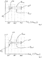
- FIG. 2 to 4 shows on the x-axis the fan speed n of the fan 14 and on the y-axis the absolute throttle position P of the throttle 17.
- the fan speed n of the fan is shown as percentage of the maximum fan speed n MAX , wherein a fan speed n of 20% means 20% of maximum fan speed n MAX and thereby a modulation of "5", wherein a fan speed n of 60% means 60% of maximum fan speed n MAX and thereby a modulation of "1.67”, and wherein a fan speed n of 100% means 100% of maximum fan speed n MAX and thereby a modulation of "1".
- the calibration is performed at any fan speed within a predefined fan speed range and thereby at any burner load within a predefined burner load range.
- the predefined fan speed range, in which the calibration is performed is between 20% of maximum fan speed n MAX and 100% of maximum fan speed n MAX . So, the predefined burner load range, in which the calibration is performed, is between a modulation of "1" and a modulation of "5".
- the upper limit of said predefined fan speed range or burner load range, in which said the calibration is performed, is at 100% of maximum fan speed or at a modulation of "1".
- the lower limit of said predefined fan speed range or burner load range, in which said the calibration is performed is at least at 20% of maximum fan speed or at least at a modulation of "5".
- the lower limit of said predefined fan speed range or burner load range, in which said the calibration is performed can also be at 15% of maximum fan speed and thereby at a modulation of "6.67" or at 10% of maximum fan speed and thereby at a modulation of "10".
- the absolute throttle position P1 and the absolute throttle position P2 are both within the defined range ⁇ P so that no drift of the pneumatic controller 24 and no blockage of the air intake and no blockage of the exhaust gas chimney 26 becomes detected.
- the upper threshold P MAX and the lower threshold P MIN defining the range ⁇ P depend both from a throttle calibration performed at maximum fan speed and thereby at a modulation of "1".
- Said reference throttle position is an absolute throttle position P determined after a calibration performed at a relatively high speed of the fan 14 and thereby at a relatively high burner load being higher than the respective threshold, e.g. at a fan speed above 50% of maximum fan speed n MAX and thereby at a predefined burner load above a modulation of "2".
- said absolute throttle position P which is used as reference throttle position has been determined before, preferably immediately before, or will be determined after, preferably immediately after, it has been determined that the absolute throttle position P determined after the calibration performed at a relatively low speed of the fan 14 is without the defined range ⁇ P. If said reference throttle position has been determined beforehand, the comparison with the reference throttle position can we done immediately.
- a drift of the pneumatic controller 24 or a blockage of the air intake of the gas burner appliance 10 or a blockage of the exhaust gas chimney 26 intake of the gas burner appliance 10 becomes detected when said difference between said absolute throttle positions of the throttle 17, namely between the absolute throttle position determined after calibration and the reference throttle position, is higher than a respective threshold.
- a changing gas quality is detected when said difference between said absolute positions of the throttle 17 is lower than the respective threshold.
- the above described calibration is performed during burner-on phases of the gas burner appliance 10 and started when the continuously monitored difference between the actual value of the signal provided by the combustion quality sensor and a corresponding nominal value is greater than a corresponding threshold.
- the ionization sensor 13 is used as combustion quality sensor.
- an exhaust gas sensor 27 can be used as combustion quality sensor.
- the exhaust gas sensor 26 can be an O 2 -sensor or CO-sensor.
- the throttle 17 may be opened to a predefined position to create a richer gas/air mixture for the start-up routine of the gas burner appliance 10. This richer gas/air mixture will improve ignition, but also helps to faster establish a stable combustion. When stable combustion is established, the throttle 17 will return to a position providing the defined or desired gas/air mixture.
- the above described calibration routine will not be performed during such a start-up routine.
- the above described calibration routine will only be performed after a stable combustion is established, and after the throttle 17 has returned to a position providing the defined or desired gas/air mixture.
Landscapes
- Engineering & Computer Science (AREA)
- Chemical & Material Sciences (AREA)
- Combustion & Propulsion (AREA)
- Mechanical Engineering (AREA)
- General Engineering & Computer Science (AREA)
- Regulation And Control Of Combustion (AREA)
Description
- The present patent application relates to a method for operating a gas burner appliance.
-
EP 2 667 097 A1
According toEP 2 667 097 A1 - According to
EP 2 667 097 A1 - As mentioned above,
EP 2 667 097 A1EP 2 667 097 A1 -
EP 2 685 167 A1EP 2 685 169 A1 ,EP 2 685 168 A1EP 2 966 354 A1 all disclose a method for operating a gas burner appliance using an electronic gas/air control in which the gas/air mixture is controlled by a controller on basis of a signal provided by an electrical or electric sensor. - Other prior art is known from
EP 2 631 541 A1 andEP 1 176 364 A1 . - Against this background a novel method for operating a gas burner is provided. The method arrangement for operating a gas burner according to the invention is defined in the claim 1.
- The calibration of the defined gas/air mixture is performed under the assumption of a constant gas quality at any fan speed of the fan within a predefined fan speed range and thereby at any burner load within a predefined burner load range when a difference between an actual value of the signal provided by the combustion quality sensor and a corresponding nominal value is greater than a respective threshold.
- After the calibration has been performed, the absolute throttle position is determined, wherein depending from said absolute throttle position determined after calibration at least one of the following changes of an operating condition of the gas burner appliance is detectable under the assumption of a constant gas quality: drift of the pneumatic controller, blockage of an air intake, blockage of an exhaust gas chimney, recirculation of exhaust gas.
- According to the invention, the difference between the actual value of the signal provided by the combustion quality sensor and the corresponding nominal value is continuously monitored. If said difference is too big, namely greater than the respective threshold, the calibration of the defined gas/air mixture is performed. The calibration is performed at any fan speed within the predefined fan speed range and thereby at any burner load the predefined burner load range. After the calibration is completed, the absolute throttle position of the throttle is determined, wherein depending from said absolute throttle position detected after calibration a change of an operating condition of the gas burner appliance is detectable. The invention provides the ability to determine the reason why the difference between the actual value of the signal provided by the combustion quality sensor and the corresponding nominal value is too big.
- According to a preferred embodiment, when said calibration of the defined gas/air mixture is performed at a relatively high fan speed and thereby at a relatively high burner load being larger than a respective threshold, and when the absolute throttle position determined after the calibration is within a defined range, no recirculation of exhaust gas becomes detected.
- When said calibration of the defined gas/air mixture is performed at a relatively high fan speed and thereby at a relatively high burner load being larger than a respective threshold, and when the absolute throttle position determined after the calibration is without a defined range, recirculation of exhaust gas or changing gas quality becomes detected.
- Preferably, a gas quality being too poor or - under the assumption of a constant gas quality - recirculation of exhaust gas becomes detected when the absolute throttle position is below a lower threshold of the defined range. A gas quality being too rich becomes detected when the absolute throttle position is above an upper threshold of the defined range.
- The invention provides the ability to determine the reason why the difference between the actual value of the signal provided by the combustion quality sensor and the corresponding nominal value is too big, under the assumption of a constant gas quality, for other reasons than a changing gas quality.
- Preferably, when said calibration of the defined gas/air mixture is performed at a relatively low speed of the fan and thereby at a relatively low burner load being lower than a respective threshold, and when the absolute throttle position after the calibration is without a defined range, the absolute throttle after calibration is compared with an absolute throttle position determined after a calibration performed at a relatively high speed of the fan and thereby at a relatively high burner load being higher than the respective threshold.
- A drift of the pneumatic controller or a blockage of the air intake of the gas burner or a blockage of the exhaust gas chimney becomes detected when a difference between said absolute throttle positions of the throttle is higher than a respective threshold. A changing gas quality is detected when said difference between said absolute positions of the throttle is lower than a respective threshold.
- The invention provides the ability to determine the reason why the difference between the actual value of the signal provided by the combustion quality sensor and the corresponding nominal value is too big, for other reasons than a changing gas quality.
- Preferred developments of the invention are provided by the dependent claims and the description which follows. Exemplary embodiments are explained in more detail on the basis of the drawing, in which:
- Figure 1
- shows a schematic view of a gas burner;
- Figure 2
- shows a first diagram illustrating the method for operating a gas burner;
- Figure 3
- shows a second diagram illustrating the method for operating a gas burner;
- Figure 4
- shows a third diagram illustrating the method for operating a gas burner, and
- Figure 5
- shows a fourth diagram illustrating the method for operating a gas burner.
-
Figure 1 shows a schematic view of agas burner appliance 10. The same comprises agas burner chamber 11 with agas burner surface 25 in which combustion of a defined gas/air mixture having a defined mixing ratio of gas and air takes place during burner-on phases of thegas burner appliance 10. - The combustion of the gas/air mixture results into
flames 12 monitored by a combustion quality sensor, namely by aflame rod 13. - The defined gas/air mixture is provided to the
burner chamber 11 of thegas burner appliance 10 by mixing an air flow with a gas flow. - A
fan 14 sucks in air flowing through anair duct 15 and gas flowing though agas duct 16. - A
gas regulating valve 18 for adjusting the gas flow through thegas duct 16 and agas safety valve 19 are assigned to thegas duct 16. - The defined gas/air mixture having the defined mixing ratio of gas and air is provided to the
burner chamber 11 of thegas burner appliance 10. The defined gas/air mixture is provided by mixing the air flow provided by anair duct 15 with a gas flow provided by agas duct 16. The air flow and the gas flow become preferably mixed by amixing device 23. Such a mixing device can be designed as a so-called Venturi nozzle. - The quantity of the air flow and thereby the quantity of the gas/air mixture flow is adjusted by the
fan 14, namely by the speed of thefan 14. The fan speed can be adjusted by anactuator 22 of thefan 14. - The fan speed of the
fan 14 is controlled by acontroller 20 generating a control variable for theactuator 22 of thefan 14. - The defined mixing ratio of the defined gas/air mixture is controlled by the
gas regulating valve 18, namely by apneumatic controller 24 of the same. Thepneumatic controller 24 of thegas regulating valve 18 controls the opening/closing position of thegas valve 18. - The position of the
gas valve 18 is adjusted by thepneumatic controller 24 on basis of a pressure difference between the gas pressure of the gas flow in thegas pipe 16 and a reference pressure. Thegas regulating valve 18 is controlled by thepneumatic controller 24 in such a way that at the outlet pressure of thegas valve 18 is equal to the reference pressure. - In
Figure 1 , the ambient pressure serves as reference pressure. However, it is also possible to use the air pressure of the air flow in theair duct 15 as reference pressure. The pressure difference between the gas pressure and the reference pressure is determined pneumatically by pneumatic sensor of thepneumatic controller 24. - The mixing ratio of the defined gas/air mixture is controlled by the
pneumatic controller 24 in such a way that over the entire modulation range of thegas burner appliance 10 the defined mixing ratio of the defined gas/air mixture is kept constant. A modulation of "1" means that thefan 14 is operated at maximum fan speed (100% of maximum fay speed) and thereby at full-load of thegas burner appliance 10. A modulation of "2" means that thefan 14 is operated at 50% of the maximum fan speed and a modulation of "5" means that thefan 14 is operated at 20% of the maximum fan speed. - By changing the fan speed of the
fan 14, the load of thegas burner appliance 10 can be adjusted. Over the entire modulation range of thegas burner appliance 10 the defined mixing ratio of the defined gas/air mixture is kept constant. - As described above, the mixing ratio of the defined gas/air mixture is controlled during burner-on phases by the
pneumatic controller 24 so that over the entire modulation range of thegas burner appliance 10 the defined mixing ratio of the gas/air mixture is kept constant. - During burner-on phases the defined mixing ratio of gas and air of the defined gas/air mixture can be calibrated.
- The calibration is performed by adjusting a position of a
throttle 17 within thegas duct 16. The throttle position of thethrottle 17 can be adjusted by anactuator 21 assigned to thethrottle 17. Thecontroller 20 controls theactuator 21 and thereby the throttle position of thethrottle 17 during calibration. - The absolute throttle position of the
throttle 17 after calibration can be determined in different ways. With use of a stepper motor asactuator 21, the actual absolute throttle position of thethrottle 17 can be determined by counting steps of the stepper motor. With use of a solenoid asactuator 21, the actual absolute throttle position of thethrottle 17 can be determined by measuring/controlling the electrical current of the same. It is also possible to determine the absolute throttle position of thethrottle 17 after calibration by using a position feedback provided by a sensing element like a Hall sensor assigned to thethrottle 17. - The calibration of the defined gas/air mixture as disclosed is performed at any speed of the fan within a predefined fan speed range and thereby at any burner load within a predefined burner load range, namely when a difference between an actual value of the signal provided by the combustion quality sensor, namely by the
ionization sensor 13, and a corresponding nominal value is greater than a threshold. The difference between the actual value of the signal provided by theionization sensor 13 and the corresponding nominal value is determined outside a calibration routine. When said difference becomes too big, the calibration is started. - The nominal value for the signal provided by the
ionization sensor 13 is stored within thecontroller 20. - Said nominal value for the signal provided by the
ionization sensor 13 is preferably the ionization current recorded directly after the last calibration routine. - After the calibration has been completed, the absolute throttle position of the
throttle 17 is determined, wherein depending from said absolute throttle position determined after calibration a change of an operating condition of thegas burner appliance 10 is detectable. - So, the difference between the actual value of the signal provided by the combustion quality sensor, namely by the
ionization sensor 13, and the corresponding nominal value is continuously monitored. If said difference is too big, namely greater than the respective threshold, the calibration of the defined gas/air mixture is performed. - The calibration is performed at any fan speed within the predefined fan speed range and thereby at any burner load within the predefined burner load range. After the calibration is completed, an absolute throttle position of the
throttle 17 is determined, wherein depending from said absolute throttle position determined after calibration a change of an operating condition of the gas burner becomes detected. - The calibration of the defined gas/air mixture is performed under the assumption of a constant gas quality. Depending from said absolute throttle position of the
throttle 17 determined after calibration, at least one of the following changes of operating conditions of the gas burner is detectable under said assumption of a constant gas quality: drift of thepneumatic controller 24 of thegas burner appliance 10, blockage of an air intake of thegas burner appliance 10, blockage of anexhaust gas chimney 26 of thegas burner appliance 10, recirculation of exhaust gas into the air or the gas/air mixture within thegas burner appliance 10. - The invention provides the ability to determine the reason why the difference between the actual value of the signal provided by the combustion quality sensor, namely by the
ionization sensor 13, and the corresponding nominal value is too big, under the assumption of a constant gas quality, for other reasons than a changing gas quality. - A constant gas quality can be assumed for many gas burner appliances, especially for gas burner appliances installed in countries in which the gas quality does not or hardly change, like in Germany, The Netherlands or in other countries proving a stable gas quality to customers.
- Additional details of the invention will be described below under reference to
Figures 2 to 4 . Each ofFigures 2 to 4 shows on the x-axis the fan speed n of thefan 14 and on the y-axis the absolute throttle position P of thethrottle 17. - The fan speed n of the fan is shown as percentage of the maximum fan speed nMAX, wherein a fan speed n of 20% means 20% of maximum fan speed nMAX and thereby a modulation of "5", wherein a fan speed n of 60% means 60% of maximum fan speed nMAX and thereby a modulation of "1.67", and wherein a fan speed n of 100% means 100% of maximum fan speed nMAX and thereby a modulation of "1".
- As described above, the calibration is performed at any fan speed within a predefined fan speed range and thereby at any burner load within a predefined burner load range. In the shown embodiments, the predefined fan speed range, in which the calibration is performed, is between 20% of maximum fan speed nMAX and 100% of maximum fan speed nMAX. So, the predefined burner load range, in which the calibration is performed, is between a modulation of "1" and a modulation of "5".
- The upper limit of said predefined fan speed range or burner load range, in which said the calibration is performed, is at 100% of maximum fan speed or at a modulation of "1".
- The lower limit of said predefined fan speed range or burner load range, in which said the calibration is performed, is at least at 20% of maximum fan speed or at least at a modulation of "5". The lower limit of said predefined fan speed range or burner load range, in which said the calibration is performed, can also be at 15% of maximum fan speed and thereby at a modulation of "6.67" or at 10% of maximum fan speed and thereby at a modulation of "10".
- When said calibration of the defined gas/air mixture is performed at a relatively low fan speed of the
fan 14 and thereby at a relatively low burner load being lower than a respective threshold, e.g. at a fan speed below 50% of maximum fan speed nMAX, preferably at a fan speed below 40% of maximum fan speed nMAX, most preferably at a fan speed below 33.33% of maximum fan speed nMAX, meaning at a predefined burner load below a modulation of "2", preferably at a predefined burner load below a modulation of "2.5", most preferably at a predefined burner load below a modulation of "3", and when further the absolute throttle position P determined after the calibration is within a defined range ΔP defined by an upper threshold PMAX and a lower threshold PMIN, no drift of thepneumatic controller 24 and no blockage of the air intake and no blockage of theexhaust gas chimney 26 becomes detected (seeFigure 2 ). - In
Figure 2 , the absolute throttle position P1 and the absolute throttle position P2 are both within the defined range ΔP so that no drift of thepneumatic controller 24 and no blockage of the air intake and no blockage of theexhaust gas chimney 26 becomes detected. - The upper threshold PMAX and the lower threshold PMIN defining the range ΔP depend both from a throttle calibration performed at maximum fan speed and thereby at a modulation of "1".
- When said calibration of the defined gas/air mixture is performed at a relatively low speed of the
fan 14 and thereby at a relatively low burner load being lower than a respective threshold, e.g. at a fan speed below 50% of maximum fan speed nMAX, preferably at a fan speed below 40% of maximum fan speed nMAX, most preferably at a fan speed below 33% of maximum fan speed nMAX - meaning at a predefined burner load below a modulation of "2", preferably at a predefined burner load below a modulation of "2.5", most preferably at a predefined burner load below a modulation of "3", and when the absolute throttle position P after the calibration is without the defined range ΔP (seeFigure 3 , the absolute throttle position P1 and the absolute throttle position P2 are at relatively low fan speeds both outside the defined range ΔP), the absolute throttle position determined after calibration is compared with a reference throttle position. Said reference throttle position is an absolute throttle position P determined after a calibration performed at a relatively high speed of thefan 14 and thereby at a relatively high burner load being higher than the respective threshold, e.g. at a fan speed above 50% of maximum fan speed nMAX and thereby at a predefined burner load above a modulation of "2". - It is possible that said absolute throttle position P which is used as reference throttle position has been determined before, preferably immediately before, or will be determined after, preferably immediately after, it has been determined that the absolute throttle position P determined after the calibration performed at a relatively low speed of the
fan 14 is without the defined range ΔP. If said reference throttle position has been determined beforehand, the comparison with the reference throttle position can we done immediately. - Otherwise, it would be necessary to modulate up the gas burner appliance for the determination of the reference throttle position.
- A drift of the
pneumatic controller 24 or a blockage of the air intake of thegas burner appliance 10 or a blockage of theexhaust gas chimney 26 intake of thegas burner appliance 10 becomes detected when said difference between said absolute throttle positions of thethrottle 17, namely between the absolute throttle position determined after calibration and the reference throttle position, is higher than a respective threshold. A changing gas quality is detected when said difference between said absolute positions of thethrottle 17 is lower than the respective threshold. - When said calibration of the defined gas/air mixture is performed at a relatively high speed of the
fan 14 and thereby at a relatively high burner load being larger than a respective threshold, e.g.at a fan speed above 50% of maximum fan speed nMAX and thereby at a predefined burner load above a modulation of "2", and when the absolute throttle position P determined after the calibration is within a defined range ΔP defined by the upper threshold PMAX and the lower threshold PMIN (seeFigure 5 ), no recirculation of exhaust gas becomes detected. - However, when the absolute throttle position determined after the calibration under these calibration conditions is without the defined range ΔP, recirculation of exhaust gas or a changing gas quality becomes detected. When the absolute throttle position P is below the lower threshold PMIN of the defined range ΔP (see curve P4 of
Figure 5 ), then a gas quality being too poor or, under the assumption of a constant gas quality, recirculation of exhaust gas becomes detected. However, when said absolute throttle position P is above the upper threshold PMAX of the defined range ΔP (see curve P3 ofFigure 5 ), no recirculation of exhaust gas but a gas quality being too rich becomes detected. - The above described calibration is performed during burner-on phases of the
gas burner appliance 10 and started when the continuously monitored difference between the actual value of the signal provided by the combustion quality sensor and a corresponding nominal value is greater than a corresponding threshold. - In the shown embodiment, the
ionization sensor 13 is used as combustion quality sensor. Alternatively, anexhaust gas sensor 27 can be used as combustion quality sensor. Theexhaust gas sensor 26 can be an O2-sensor or CO-sensor. - It should be noted that most
gas burner appliances 10 have ignition problems at low temperatures or with gas/air mixtures set to a so-called lambda value being greater than 1.25. So, for a start-up routine at low temperatures of thegas burner appliance 10 or for a start-up routine with gas/air mixtures set to a so-called lambda value being greater than 1.25, thethrottle 17 may be opened to a predefined position to create a richer gas/air mixture for the start-up routine of thegas burner appliance 10. This richer gas/air mixture will improve ignition, but also helps to faster establish a stable combustion. When stable combustion is established, thethrottle 17 will return to a position providing the defined or desired gas/air mixture. - The above described calibration routine will not be performed during such a start-up routine. The above described calibration routine will only be performed after a stable combustion is established, and after the
throttle 17 has returned to a position providing the defined or desired gas/air mixture. -
- 10
- gas burner appliance
- 11
- gas burner chamber
- 12
- flame
- 13
- flame rod
- 15
- air duct
- 16
- gas duct
- 17
- throttle
- 18
- gas valve / regulating valve
- 19
- gas valve / safety valve
- 20
- controller
- 21
- actuator
- 22
- actuator
- 23
- mixing device
- 24
- pneumatic controller
- 25
- gas burner surface
- 26
- exhaust gas chimney
- 27
- exhaust gas sensor
Claims (8)
- Method for operating a gas burner appliance (10), whereinduring burner-on phases a defined gas/air mixture having a defined mixing ratio of gas and air is provided to a burner chamber (11) of the gas burner appliance (10) for combusting the defined gas/air mixture within the burner chamber (11);said defined gas/air mixture is provided by a mixing device (23) mixing an air flow provided by an air duct (15) with a gas flow provided by a gas duct (16);said air flow flowing through the air duct (15) is provided by fan (14) in such a way that the fan speed of the fan (14) depends on a desired burner load of the gas burner appliance (10), wherein the fan speed range of the fan (14) defines a modulation range of the gas burner appliance (10);said mixing ratio of gas and air of the gas/air mixture is controlled over the modulation range of the gas burner appliance (10) by a pneumatic controller (24) on basis of a pressure difference between the gas pressure of the gas flow in the gas duct (16) and a reference pressure, wherein either the air pressure of the air flow in the air duct (15) or the ambient pressure is used as reference pressure, and wherein the pressure difference between the gas pressure and the reference pressure is determined and controlled pneumatically;during burner on phases the combustion quality is monitored on basis of a signal provided by a combustion quality sensor like a flame ionization sensor (13), wherein the defined mixing ratio of gas and air of the defined gas/air mixture can be calibrated on basis of the signal provided by the combustion quality sensor, namely by adjusting during calibration a position of a throttle (17) within the gas duct (16);characterized in thatthe calibration of the gas/air mixture is performed under the assumption of a constant gas quality at any fan speed of the fan (14) within a predefined fan speed range and thereby at any burner load within a predefined burner load range when a difference between an actual value of the signal provided by the combustion quality sensor and a corresponding nominal value is greater than a threshold; and in thatafter the calibration has been performed, an absolute throttle position of the throttle (17) is determined, wherein depending from said absolute throttle position determined after calibration at least one of the following changes of an operating condition of the gas burner appliance (10) is detectable under the assumption of a constant gas quality: drift of the pneumatic controller (24), blockage of an air intake, blockage of an exhaust gas chimney (26), recirculation of exhaust gas.
- Method as claimed in claim 1, characterized in that when said calibration of the defined gas/air mixture is performed at a relatively high fan speed of the fan (14) and thereby at a relatively high burner load being larger than a respective threshold, and when the absolute throttle position determined after the calibration is within a defined range, no recirculation of exhaust gas becomes detected.
- Method as claimed in claim 1 or 2, characterized in that when said calibration of the defined gas/air mixture is performed at a relatively high fan speed of the fan (14) and thereby at a relatively high burner load being larger than a respective threshold, and when the absolute throttle position determined after the calibration is without a defined range, recirculation of exhaust gas or changing gas quality becomes detected.
- Method as claimed in claim 3, characterized in that when said absolute throttle position is below a lower threshold of the defined range, a gas quality being too poor or, under the assumption of a constant gas quality, recirculation of exhaust gas becomes detected.
- Method as claimed in claim 3, characterized in that when said absolute throttle position is above an upper threshold of the defined range, a gas quality being too rich becomes detected.
- Method as claimed in one of claims 1 to 5, characterized in that when said calibration of the defined gas/air mixture is performed at a relatively low fan speed of the fan (14) and thereby at a relatively low burner load being lower than a respective threshold, and when the absolute throttle position determined after the calibration is within a defined range, no drift of the pneumatic controller (24) and no blockage of the air intake and no blockage of the exhaust gas chimney (26) becomes detected.
- Method as claimed in one of claims 1 to 6, characterized in that when said calibration of the defined gas/air mixture is performed at a relatively low fan speed of the fan (14) and thereby at a relatively low burner load being lower than a respective threshold, and when the absolute throttle position determined after the calibration is without a defined range, said absolute throttle position is compared with an absolute throttle position determined after a calibration performed at a relatively high fan speed of the fan (14) and thereby at a relatively high burner load being higher than the respective threshold, wherein drift of the pneumatic controller (24) or blockage of the air intake of the gas burner appliance or a blockage of the exhaust gas chimney (26) becomes detected when a difference between said absolute throttle positions of the throttle (17) is higher than a respective threshold.
- Method as claimed in one of claims 1 to 7, characterized in that when said calibration of the defined gas/air mixture is performed at a relatively low fan speed of the fan (14) and thereby at a relatively low burner load being lower than a respective threshold, and when the absolute throttle position determined after the calibration is without a defined range, said absolute throttle position is compared with an absolute throttle position determined after a calibration performed at a relatively high fan speed of the fan (14) and thereby at a relatively high burner load being higher than the threshold, wherein changing gas quality is detected when a difference between said absolute positions of the throttle (17) is lower than a respective threshold.
Priority Applications (2)
| Application Number | Priority Date | Filing Date | Title |
|---|---|---|---|
| EP16164170.9A EP3228936B1 (en) | 2016-04-07 | 2016-04-07 | Method for operating a gas burner appliance |
| US15/482,403 US10520186B2 (en) | 2016-04-07 | 2017-04-07 | Method for operating a gas burner appliance |
Applications Claiming Priority (1)
| Application Number | Priority Date | Filing Date | Title |
|---|---|---|---|
| EP16164170.9A EP3228936B1 (en) | 2016-04-07 | 2016-04-07 | Method for operating a gas burner appliance |
Publications (2)
| Publication Number | Publication Date |
|---|---|
| EP3228936A1 EP3228936A1 (en) | 2017-10-11 |
| EP3228936B1 true EP3228936B1 (en) | 2020-06-03 |
Family
ID=55699510
Family Applications (1)
| Application Number | Title | Priority Date | Filing Date |
|---|---|---|---|
| EP16164170.9A Active EP3228936B1 (en) | 2016-04-07 | 2016-04-07 | Method for operating a gas burner appliance |
Country Status (2)
| Country | Link |
|---|---|
| US (1) | US10520186B2 (en) |
| EP (1) | EP3228936B1 (en) |
Families Citing this family (15)
| Publication number | Priority date | Publication date | Assignee | Title |
|---|---|---|---|---|
| KR101601709B1 (en) * | 2014-04-22 | 2016-03-10 | 주식회사 경동나비엔 | Method for sensing exhaust port closure of gas boiler |
| KR101709534B1 (en) * | 2016-01-06 | 2017-02-23 | 주식회사 경동나비엔 | Combustion apparatus capable of measuring of gas amount used and the measuring method of gas amount |
| US10677469B2 (en) * | 2017-10-19 | 2020-06-09 | Haier Us Appliance Solutions, Inc. | Fuel supply system for a gas burner assembly |
| EP3477201B1 (en) * | 2017-10-26 | 2020-05-06 | Honeywell Technologies Sarl | Method for operating a gas burner appliance |
| IT201800010736A1 (en) * | 2018-11-30 | 2020-05-30 | Bertelli & Partners Srl | MIXTURE CONTROL DEVICE FOR PRE-MIXED GAS BURNER |
| CN114486232B (en) * | 2020-11-12 | 2023-09-22 | 珠海优特电力科技股份有限公司 | Valve state calibration method and device, target detection equipment and storage medium |
| US12098867B1 (en) * | 2020-12-22 | 2024-09-24 | A.O. Smith Corporation | Water heating system and method of operating the same |
| DE102021104191A1 (en) * | 2021-02-23 | 2022-08-25 | Vaillant Gmbh | Method for operating a heater with an electronic gas-air compound |
| JP7538759B2 (en) * | 2021-03-23 | 2024-08-22 | リンナイ株式会社 | Premixing Device |
| JP7697862B2 (en) * | 2021-10-12 | 2025-06-24 | リンナイ株式会社 | premixing device |
| DE102022101305A1 (en) * | 2022-01-20 | 2023-07-20 | Ebm-Papst Landshut Gmbh | Procedure for failsafe and lean ignition of a combustible gas-air mixture on a gas burner |
| JP2024002212A (en) * | 2022-06-23 | 2024-01-11 | リンナイ株式会社 | combustion device |
| EP4336075A1 (en) * | 2022-09-08 | 2024-03-13 | Pittway Sarl | Systems and methods for measuring throttle position |
| EP4336076B1 (en) * | 2022-09-08 | 2025-11-12 | Pittway Sarl | Systems and methods for measuring throttle position |
| US12385638B2 (en) * | 2023-02-27 | 2025-08-12 | Copeland Comfort Control Lp | Electronic pressure augmented modulation |
Citations (1)
| Publication number | Priority date | Publication date | Assignee | Title |
|---|---|---|---|---|
| EP2667097A1 (en) * | 2012-05-24 | 2013-11-27 | Honeywell Technologies Sarl | Method for operating a gas burner |
Family Cites Families (16)
| Publication number | Priority date | Publication date | Assignee | Title |
|---|---|---|---|---|
| DE19618573C1 (en) | 1996-05-09 | 1997-06-26 | Stiebel Eltron Gmbh & Co Kg | Gas burner regulating method controlled by ionisation electrode signal |
| EP0861402A1 (en) | 1995-11-13 | 1998-09-02 | Gas Research Institute | Flame ionization control apparatus and method |
| ES2158400T3 (en) | 1996-05-09 | 2001-09-01 | Stiebel Eltron Gmbh & Co Kg | PROCEDURE FOR THE OPERATION OF A GAS BURNER. |
| NL1015797C2 (en) * | 2000-07-25 | 2002-01-28 | Nefit Buderus B V | Combustion device and method for controlling a combustion device. |
| ES2253314T3 (en) * | 2001-09-13 | 2006-06-01 | Siemens Schweiz Ag | REGULATION INSTALLATION FOR A BURNER AND REGULATION PROCEDURE. |
| ITAN20020038A1 (en) | 2002-08-05 | 2004-02-06 | Merloni Termosanitari Spa Ora Ariston Thermo Spa | LAMBDA VIRTUAL SENSOR COMBUSTION CONTROL SYSTEM. |
| US8303297B2 (en) * | 2007-10-31 | 2012-11-06 | Webster Engineering & Manufacturing Co., Llc | Method and apparatus for controlling combustion in a burner |
| EP2631541B1 (en) * | 2012-02-27 | 2018-04-11 | Honeywell Technologies Sarl | Method for operating a gas burner |
| EP2685168B1 (en) * | 2012-07-13 | 2015-10-14 | Honeywell Technologies Sarl | Method for operating a gas burner |
| EP2685169B1 (en) * | 2012-07-13 | 2018-10-24 | Honeywell Technologies Sarl | Method for operating a gas burner |
| EP2685167B1 (en) * | 2012-07-13 | 2015-12-16 | Honeywell Technologies Sarl | Method for operating a gas burner |
| US9234661B2 (en) * | 2012-09-15 | 2016-01-12 | Honeywell International Inc. | Burner control system |
| ITBO20120568A1 (en) * | 2012-10-17 | 2014-04-18 | Gas Point S R L | ADJUSTMENT AND CONTROL EQUIPMENT FOR COMBUSTION IN A FUEL GAS BURNER |
| EP2966354B1 (en) * | 2014-07-08 | 2017-11-29 | Honeywell Technologies Sarl | Method for operating a gas burner |
| EP3073195B1 (en) * | 2015-03-23 | 2019-05-08 | Honeywell Technologies Sarl | Method for calibrating a gas burner |
| US11073281B2 (en) * | 2017-12-29 | 2021-07-27 | Honeywell International Inc. | Closed-loop programming and control of a combustion appliance |
-
2016
- 2016-04-07 EP EP16164170.9A patent/EP3228936B1/en active Active
-
2017
- 2017-04-07 US US15/482,403 patent/US10520186B2/en active Active
Patent Citations (1)
| Publication number | Priority date | Publication date | Assignee | Title |
|---|---|---|---|---|
| EP2667097A1 (en) * | 2012-05-24 | 2013-11-27 | Honeywell Technologies Sarl | Method for operating a gas burner |
Also Published As
| Publication number | Publication date |
|---|---|
| US10520186B2 (en) | 2019-12-31 |
| US20170292698A1 (en) | 2017-10-12 |
| EP3228936A1 (en) | 2017-10-11 |
Similar Documents
| Publication | Publication Date | Title |
|---|---|---|
| US10520186B2 (en) | Method for operating a gas burner appliance | |
| US9134026B2 (en) | Method for operating a gas burner | |
| EP2667097B1 (en) | Method for operating a gas burner | |
| EP2685169B1 (en) | Method for operating a gas burner | |
| EP2631541B1 (en) | Method for operating a gas burner | |
| US11635206B2 (en) | Method and controller for operating a gas burner appliance | |
| EP2685168B1 (en) | Method for operating a gas burner | |
| EP3043115B1 (en) | Method for operating a premix gas burner | |
| EP4092325B1 (en) | Method and controller for operating a gas burner appliance | |
| US20240328621A1 (en) | Method and Controller for Operating a Gas Burner Appliance | |
| EP2685167B1 (en) | Method for operating a gas burner | |
| US11287131B2 (en) | Method for operating a gas burner appliance | |
| US20240337385A1 (en) | Method and Controller for Operating a Gas Burner Appliance | |
| US20230090905A1 (en) | Flame monitoring device for a gas burner appliance and gas burner appliance | |
| US20240401804A1 (en) | Method and controller for operating a gas burner appliance | |
| EP4033148B1 (en) | Method and controller for operating a gas burner appliance | |
| US12631331B2 (en) | Method and controller for operating a gas burner appliance | |
| EP3699492A1 (en) | Method and controller for operating a gas burner appliance |
Legal Events
| Date | Code | Title | Description |
|---|---|---|---|
| PUAI | Public reference made under article 153(3) epc to a published international application that has entered the european phase |
Free format text: ORIGINAL CODE: 0009012 |
|
| STAA | Information on the status of an ep patent application or granted ep patent |
Free format text: STATUS: THE APPLICATION HAS BEEN PUBLISHED |
|
| AK | Designated contracting states |
Kind code of ref document: A1 Designated state(s): AL AT BE BG CH CY CZ DE DK EE ES FI FR GB GR HR HU IE IS IT LI LT LU LV MC MK MT NL NO PL PT RO RS SE SI SK SM TR |
|
| AX | Request for extension of the european patent |
Extension state: BA ME |
|
| STAA | Information on the status of an ep patent application or granted ep patent |
Free format text: STATUS: REQUEST FOR EXAMINATION WAS MADE |
|
| 17P | Request for examination filed |
Effective date: 20180406 |
|
| RBV | Designated contracting states (corrected) |
Designated state(s): AL AT BE BG CH CY CZ DE DK EE ES FI FR GB GR HR HU IE IS IT LI LT LU LV MC MK MT NL NO PL PT RO RS SE SI SK SM TR |
|
| GRAP | Despatch of communication of intention to grant a patent |
Free format text: ORIGINAL CODE: EPIDOSNIGR1 |
|
| STAA | Information on the status of an ep patent application or granted ep patent |
Free format text: STATUS: GRANT OF PATENT IS INTENDED |
|
| INTG | Intention to grant announced |
Effective date: 20191023 |
|
| GRAS | Grant fee paid |
Free format text: ORIGINAL CODE: EPIDOSNIGR3 |
|
| GRAJ | Information related to disapproval of communication of intention to grant by the applicant or resumption of examination proceedings by the epo deleted |
Free format text: ORIGINAL CODE: EPIDOSDIGR1 |
|
| GRAL | Information related to payment of fee for publishing/printing deleted |
Free format text: ORIGINAL CODE: EPIDOSDIGR3 |
|
| STAA | Information on the status of an ep patent application or granted ep patent |
Free format text: STATUS: REQUEST FOR EXAMINATION WAS MADE |
|
| GRAP | Despatch of communication of intention to grant a patent |
Free format text: ORIGINAL CODE: EPIDOSNIGR1 |
|
| STAA | Information on the status of an ep patent application or granted ep patent |
Free format text: STATUS: GRANT OF PATENT IS INTENDED |
|
| INTC | Intention to grant announced (deleted) | ||
| INTG | Intention to grant announced |
Effective date: 20200320 |
|
| GRAA | (expected) grant |
Free format text: ORIGINAL CODE: 0009210 |
|
| STAA | Information on the status of an ep patent application or granted ep patent |
Free format text: STATUS: THE PATENT HAS BEEN GRANTED |
|
| AK | Designated contracting states |
Kind code of ref document: B1 Designated state(s): AL AT BE BG CH CY CZ DE DK EE ES FI FR GB GR HR HU IE IS IT LI LT LU LV MC MK MT NL NO PL PT RO RS SE SI SK SM TR |
|
| REG | Reference to a national code |
Ref country code: GB Ref legal event code: FG4D |
|
| REG | Reference to a national code |
Ref country code: CH Ref legal event code: EP Ref country code: AT Ref legal event code: REF Ref document number: 1277386 Country of ref document: AT Kind code of ref document: T Effective date: 20200615 |
|
| REG | Reference to a national code |
Ref country code: DE Ref legal event code: R096 Ref document number: 602016037349 Country of ref document: DE |
|
| REG | Reference to a national code |
Ref country code: NL Ref legal event code: FP |
|
| REG | Reference to a national code |
Ref country code: LT Ref legal event code: MG4D |
|
| PG25 | Lapsed in a contracting state [announced via postgrant information from national office to epo] |
Ref country code: FI Free format text: LAPSE BECAUSE OF FAILURE TO SUBMIT A TRANSLATION OF THE DESCRIPTION OR TO PAY THE FEE WITHIN THE PRESCRIBED TIME-LIMIT Effective date: 20200603 Ref country code: GR Free format text: LAPSE BECAUSE OF FAILURE TO SUBMIT A TRANSLATION OF THE DESCRIPTION OR TO PAY THE FEE WITHIN THE PRESCRIBED TIME-LIMIT Effective date: 20200904 Ref country code: SE Free format text: LAPSE BECAUSE OF FAILURE TO SUBMIT A TRANSLATION OF THE DESCRIPTION OR TO PAY THE FEE WITHIN THE PRESCRIBED TIME-LIMIT Effective date: 20200603 Ref country code: NO Free format text: LAPSE BECAUSE OF FAILURE TO SUBMIT A TRANSLATION OF THE DESCRIPTION OR TO PAY THE FEE WITHIN THE PRESCRIBED TIME-LIMIT Effective date: 20200903 Ref country code: LT Free format text: LAPSE BECAUSE OF FAILURE TO SUBMIT A TRANSLATION OF THE DESCRIPTION OR TO PAY THE FEE WITHIN THE PRESCRIBED TIME-LIMIT Effective date: 20200603 |
|
| PG25 | Lapsed in a contracting state [announced via postgrant information from national office to epo] |
Ref country code: RS Free format text: LAPSE BECAUSE OF FAILURE TO SUBMIT A TRANSLATION OF THE DESCRIPTION OR TO PAY THE FEE WITHIN THE PRESCRIBED TIME-LIMIT Effective date: 20200603 Ref country code: BG Free format text: LAPSE BECAUSE OF FAILURE TO SUBMIT A TRANSLATION OF THE DESCRIPTION OR TO PAY THE FEE WITHIN THE PRESCRIBED TIME-LIMIT Effective date: 20200903 Ref country code: HR Free format text: LAPSE BECAUSE OF FAILURE TO SUBMIT A TRANSLATION OF THE DESCRIPTION OR TO PAY THE FEE WITHIN THE PRESCRIBED TIME-LIMIT Effective date: 20200603 Ref country code: LV Free format text: LAPSE BECAUSE OF FAILURE TO SUBMIT A TRANSLATION OF THE DESCRIPTION OR TO PAY THE FEE WITHIN THE PRESCRIBED TIME-LIMIT Effective date: 20200603 |
|
| REG | Reference to a national code |
Ref country code: AT Ref legal event code: MK05 Ref document number: 1277386 Country of ref document: AT Kind code of ref document: T Effective date: 20200603 |
|
| PG25 | Lapsed in a contracting state [announced via postgrant information from national office to epo] |
Ref country code: AL Free format text: LAPSE BECAUSE OF FAILURE TO SUBMIT A TRANSLATION OF THE DESCRIPTION OR TO PAY THE FEE WITHIN THE PRESCRIBED TIME-LIMIT Effective date: 20200603 |
|
| PG25 | Lapsed in a contracting state [announced via postgrant information from national office to epo] |
Ref country code: ES Free format text: LAPSE BECAUSE OF FAILURE TO SUBMIT A TRANSLATION OF THE DESCRIPTION OR TO PAY THE FEE WITHIN THE PRESCRIBED TIME-LIMIT Effective date: 20200603 Ref country code: AT Free format text: LAPSE BECAUSE OF FAILURE TO SUBMIT A TRANSLATION OF THE DESCRIPTION OR TO PAY THE FEE WITHIN THE PRESCRIBED TIME-LIMIT Effective date: 20200603 Ref country code: PT Free format text: LAPSE BECAUSE OF FAILURE TO SUBMIT A TRANSLATION OF THE DESCRIPTION OR TO PAY THE FEE WITHIN THE PRESCRIBED TIME-LIMIT Effective date: 20201006 Ref country code: SM Free format text: LAPSE BECAUSE OF FAILURE TO SUBMIT A TRANSLATION OF THE DESCRIPTION OR TO PAY THE FEE WITHIN THE PRESCRIBED TIME-LIMIT Effective date: 20200603 Ref country code: EE Free format text: LAPSE BECAUSE OF FAILURE TO SUBMIT A TRANSLATION OF THE DESCRIPTION OR TO PAY THE FEE WITHIN THE PRESCRIBED TIME-LIMIT Effective date: 20200603 Ref country code: CZ Free format text: LAPSE BECAUSE OF FAILURE TO SUBMIT A TRANSLATION OF THE DESCRIPTION OR TO PAY THE FEE WITHIN THE PRESCRIBED TIME-LIMIT Effective date: 20200603 Ref country code: RO Free format text: LAPSE BECAUSE OF FAILURE TO SUBMIT A TRANSLATION OF THE DESCRIPTION OR TO PAY THE FEE WITHIN THE PRESCRIBED TIME-LIMIT Effective date: 20200603 |
|
| PG25 | Lapsed in a contracting state [announced via postgrant information from national office to epo] |
Ref country code: PL Free format text: LAPSE BECAUSE OF FAILURE TO SUBMIT A TRANSLATION OF THE DESCRIPTION OR TO PAY THE FEE WITHIN THE PRESCRIBED TIME-LIMIT Effective date: 20200603 Ref country code: SK Free format text: LAPSE BECAUSE OF FAILURE TO SUBMIT A TRANSLATION OF THE DESCRIPTION OR TO PAY THE FEE WITHIN THE PRESCRIBED TIME-LIMIT Effective date: 20200603 Ref country code: IS Free format text: LAPSE BECAUSE OF FAILURE TO SUBMIT A TRANSLATION OF THE DESCRIPTION OR TO PAY THE FEE WITHIN THE PRESCRIBED TIME-LIMIT Effective date: 20201003 |
|
| REG | Reference to a national code |
Ref country code: DE Ref legal event code: R097 Ref document number: 602016037349 Country of ref document: DE |
|
| PLBE | No opposition filed within time limit |
Free format text: ORIGINAL CODE: 0009261 |
|
| STAA | Information on the status of an ep patent application or granted ep patent |
Free format text: STATUS: NO OPPOSITION FILED WITHIN TIME LIMIT |
|
| PG25 | Lapsed in a contracting state [announced via postgrant information from national office to epo] |
Ref country code: DK Free format text: LAPSE BECAUSE OF FAILURE TO SUBMIT A TRANSLATION OF THE DESCRIPTION OR TO PAY THE FEE WITHIN THE PRESCRIBED TIME-LIMIT Effective date: 20200603 |
|
| 26N | No opposition filed |
Effective date: 20210304 |
|
| PG25 | Lapsed in a contracting state [announced via postgrant information from national office to epo] |
Ref country code: SI Free format text: LAPSE BECAUSE OF FAILURE TO SUBMIT A TRANSLATION OF THE DESCRIPTION OR TO PAY THE FEE WITHIN THE PRESCRIBED TIME-LIMIT Effective date: 20200603 |
|
| REG | Reference to a national code |
Ref country code: DE Ref legal event code: R081 Ref document number: 602016037349 Country of ref document: DE Owner name: PITTWAY SARL, CH Free format text: FORMER OWNER: HONEYWELL TECHNOLOGIES SARL, ROLLE, CH |
|
| PG25 | Lapsed in a contracting state [announced via postgrant information from national office to epo] |
Ref country code: MC Free format text: LAPSE BECAUSE OF FAILURE TO SUBMIT A TRANSLATION OF THE DESCRIPTION OR TO PAY THE FEE WITHIN THE PRESCRIBED TIME-LIMIT Effective date: 20200603 |
|
| PG25 | Lapsed in a contracting state [announced via postgrant information from national office to epo] |
Ref country code: LU Free format text: LAPSE BECAUSE OF NON-PAYMENT OF DUE FEES Effective date: 20210407 |
|
| REG | Reference to a national code |
Ref country code: BE Ref legal event code: MM Effective date: 20210430 |
|
| PG25 | Lapsed in a contracting state [announced via postgrant information from national office to epo] |
Ref country code: FR Free format text: LAPSE BECAUSE OF NON-PAYMENT OF DUE FEES Effective date: 20210430 Ref country code: CH Free format text: LAPSE BECAUSE OF NON-PAYMENT OF DUE FEES Effective date: 20210430 Ref country code: LI Free format text: LAPSE BECAUSE OF NON-PAYMENT OF DUE FEES Effective date: 20210430 |
|
| PG25 | Lapsed in a contracting state [announced via postgrant information from national office to epo] |
Ref country code: IE Free format text: LAPSE BECAUSE OF NON-PAYMENT OF DUE FEES Effective date: 20210407 |
|
| PG25 | Lapsed in a contracting state [announced via postgrant information from national office to epo] |
Ref country code: IS Free format text: LAPSE BECAUSE OF FAILURE TO SUBMIT A TRANSLATION OF THE DESCRIPTION OR TO PAY THE FEE WITHIN THE PRESCRIBED TIME-LIMIT Effective date: 20201003 |
|
| REG | Reference to a national code |
Ref country code: GB Ref legal event code: 732E Free format text: REGISTERED BETWEEN 20220505 AND 20220512 |
|
| PG25 | Lapsed in a contracting state [announced via postgrant information from national office to epo] |
Ref country code: BE Free format text: LAPSE BECAUSE OF NON-PAYMENT OF DUE FEES Effective date: 20210430 |
|
| REG | Reference to a national code |
Ref country code: NL Ref legal event code: PD Owner name: PITTWAY SARL; CH Free format text: DETAILS ASSIGNMENT: CHANGE OF OWNER(S), ASSIGNMENT; FORMER OWNER NAME: HONEYWELL TECHNOLOGIES SARL Effective date: 20221223 |
|
| PG25 | Lapsed in a contracting state [announced via postgrant information from national office to epo] |
Ref country code: HU Free format text: LAPSE BECAUSE OF FAILURE TO SUBMIT A TRANSLATION OF THE DESCRIPTION OR TO PAY THE FEE WITHIN THE PRESCRIBED TIME-LIMIT; INVALID AB INITIO Effective date: 20160407 |
|
| PG25 | Lapsed in a contracting state [announced via postgrant information from national office to epo] |
Ref country code: CY Free format text: LAPSE BECAUSE OF FAILURE TO SUBMIT A TRANSLATION OF THE DESCRIPTION OR TO PAY THE FEE WITHIN THE PRESCRIBED TIME-LIMIT Effective date: 20200603 |
|
| P01 | Opt-out of the competence of the unified patent court (upc) registered |
Effective date: 20230827 |
|
| PG25 | Lapsed in a contracting state [announced via postgrant information from national office to epo] |
Ref country code: MK Free format text: LAPSE BECAUSE OF FAILURE TO SUBMIT A TRANSLATION OF THE DESCRIPTION OR TO PAY THE FEE WITHIN THE PRESCRIBED TIME-LIMIT Effective date: 20200603 |
|
| PG25 | Lapsed in a contracting state [announced via postgrant information from national office to epo] |
Ref country code: TR Free format text: LAPSE BECAUSE OF FAILURE TO SUBMIT A TRANSLATION OF THE DESCRIPTION OR TO PAY THE FEE WITHIN THE PRESCRIBED TIME-LIMIT Effective date: 20200603 |
|
| PG25 | Lapsed in a contracting state [announced via postgrant information from national office to epo] |
Ref country code: MT Free format text: LAPSE BECAUSE OF FAILURE TO SUBMIT A TRANSLATION OF THE DESCRIPTION OR TO PAY THE FEE WITHIN THE PRESCRIBED TIME-LIMIT Effective date: 20200603 |
|
| PGFP | Annual fee paid to national office [announced via postgrant information from national office to epo] |
Ref country code: NL Payment date: 20250424 Year of fee payment: 10 |
|
| PGFP | Annual fee paid to national office [announced via postgrant information from national office to epo] |
Ref country code: DE Payment date: 20250528 Year of fee payment: 10 |
|
| PGFP | Annual fee paid to national office [announced via postgrant information from national office to epo] |
Ref country code: GB Payment date: 20250422 Year of fee payment: 10 |
|
| PGFP | Annual fee paid to national office [announced via postgrant information from national office to epo] |
Ref country code: IT Payment date: 20250422 Year of fee payment: 10 |