EP3228925A1 - Lighting device for vehicle - Google Patents
Lighting device for vehicle Download PDFInfo
- Publication number
- EP3228925A1 EP3228925A1 EP17162301.0A EP17162301A EP3228925A1 EP 3228925 A1 EP3228925 A1 EP 3228925A1 EP 17162301 A EP17162301 A EP 17162301A EP 3228925 A1 EP3228925 A1 EP 3228925A1
- Authority
- EP
- European Patent Office
- Prior art keywords
- lens
- reflecting unit
- lighting device
- fluorescent body
- light
- Prior art date
- Legal status (The legal status is an assumption and is not a legal conclusion. Google has not performed a legal analysis and makes no representation as to the accuracy of the status listed.)
- Granted
Links
Images


Classifications
-
- F—MECHANICAL ENGINEERING; LIGHTING; HEATING; WEAPONS; BLASTING
- F21—LIGHTING
- F21S—NON-PORTABLE LIGHTING DEVICES; SYSTEMS THEREOF; VEHICLE LIGHTING DEVICES SPECIALLY ADAPTED FOR VEHICLE EXTERIORS
- F21S41/00—Illuminating devices specially adapted for vehicle exteriors, e.g. headlamps
- F21S41/10—Illuminating devices specially adapted for vehicle exteriors, e.g. headlamps characterised by the light source
- F21S41/14—Illuminating devices specially adapted for vehicle exteriors, e.g. headlamps characterised by the light source characterised by the type of light source
- F21S41/16—Laser light sources
-
- B—PERFORMING OPERATIONS; TRANSPORTING
- B60—VEHICLES IN GENERAL
- B60Q—ARRANGEMENT OF SIGNALLING OR LIGHTING DEVICES, THE MOUNTING OR SUPPORTING THEREOF OR CIRCUITS THEREFOR, FOR VEHICLES IN GENERAL
- B60Q1/00—Arrangement of optical signalling or lighting devices, the mounting or supporting thereof or circuits therefor
- B60Q1/02—Arrangement of optical signalling or lighting devices, the mounting or supporting thereof or circuits therefor the devices being primarily intended to illuminate the way ahead or to illuminate other areas of way or environments
- B60Q1/04—Arrangement of optical signalling or lighting devices, the mounting or supporting thereof or circuits therefor the devices being primarily intended to illuminate the way ahead or to illuminate other areas of way or environments the devices being headlights
-
- F—MECHANICAL ENGINEERING; LIGHTING; HEATING; WEAPONS; BLASTING
- F21—LIGHTING
- F21S—NON-PORTABLE LIGHTING DEVICES; SYSTEMS THEREOF; VEHICLE LIGHTING DEVICES SPECIALLY ADAPTED FOR VEHICLE EXTERIORS
- F21S41/00—Illuminating devices specially adapted for vehicle exteriors, e.g. headlamps
- F21S41/10—Illuminating devices specially adapted for vehicle exteriors, e.g. headlamps characterised by the light source
- F21S41/14—Illuminating devices specially adapted for vehicle exteriors, e.g. headlamps characterised by the light source characterised by the type of light source
- F21S41/176—Light sources where the light is generated by photoluminescent material spaced from a primary light generating element
-
- F—MECHANICAL ENGINEERING; LIGHTING; HEATING; WEAPONS; BLASTING
- F21—LIGHTING
- F21S—NON-PORTABLE LIGHTING DEVICES; SYSTEMS THEREOF; VEHICLE LIGHTING DEVICES SPECIALLY ADAPTED FOR VEHICLE EXTERIORS
- F21S41/00—Illuminating devices specially adapted for vehicle exteriors, e.g. headlamps
- F21S41/20—Illuminating devices specially adapted for vehicle exteriors, e.g. headlamps characterised by refractors, transparent cover plates, light guides or filters
- F21S41/25—Projection lenses
- F21S41/275—Lens surfaces, e.g. coatings or surface structures
-
- F—MECHANICAL ENGINEERING; LIGHTING; HEATING; WEAPONS; BLASTING
- F21—LIGHTING
- F21S—NON-PORTABLE LIGHTING DEVICES; SYSTEMS THEREOF; VEHICLE LIGHTING DEVICES SPECIALLY ADAPTED FOR VEHICLE EXTERIORS
- F21S41/00—Illuminating devices specially adapted for vehicle exteriors, e.g. headlamps
- F21S41/30—Illuminating devices specially adapted for vehicle exteriors, e.g. headlamps characterised by reflectors
- F21S41/32—Optical layout thereof
- F21S41/36—Combinations of two or more separate reflectors
- F21S41/365—Combinations of two or more separate reflectors successively reflecting the light
-
- F—MECHANICAL ENGINEERING; LIGHTING; HEATING; WEAPONS; BLASTING
- F21—LIGHTING
- F21S—NON-PORTABLE LIGHTING DEVICES; SYSTEMS THEREOF; VEHICLE LIGHTING DEVICES SPECIALLY ADAPTED FOR VEHICLE EXTERIORS
- F21S41/00—Illuminating devices specially adapted for vehicle exteriors, e.g. headlamps
- F21S41/30—Illuminating devices specially adapted for vehicle exteriors, e.g. headlamps characterised by reflectors
- F21S41/37—Illuminating devices specially adapted for vehicle exteriors, e.g. headlamps characterised by reflectors characterised by their material, surface treatment or coatings
-
- F—MECHANICAL ENGINEERING; LIGHTING; HEATING; WEAPONS; BLASTING
- F21—LIGHTING
- F21S—NON-PORTABLE LIGHTING DEVICES; SYSTEMS THEREOF; VEHICLE LIGHTING DEVICES SPECIALLY ADAPTED FOR VEHICLE EXTERIORS
- F21S41/00—Illuminating devices specially adapted for vehicle exteriors, e.g. headlamps
- F21S41/30—Illuminating devices specially adapted for vehicle exteriors, e.g. headlamps characterised by reflectors
- F21S41/39—Attachment thereof
-
- F—MECHANICAL ENGINEERING; LIGHTING; HEATING; WEAPONS; BLASTING
- F21—LIGHTING
- F21S—NON-PORTABLE LIGHTING DEVICES; SYSTEMS THEREOF; VEHICLE LIGHTING DEVICES SPECIALLY ADAPTED FOR VEHICLE EXTERIORS
- F21S43/00—Signalling devices specially adapted for vehicle exteriors, e.g. brake lamps, direction indicator lights or reversing lights
- F21S43/10—Signalling devices specially adapted for vehicle exteriors, e.g. brake lamps, direction indicator lights or reversing lights characterised by the light source
- F21S43/13—Signalling devices specially adapted for vehicle exteriors, e.g. brake lamps, direction indicator lights or reversing lights characterised by the light source characterised by the type of light source
- F21S43/16—Light sources where the light is generated by photoluminescent material spaced from a primary light generating element
-
- F—MECHANICAL ENGINEERING; LIGHTING; HEATING; WEAPONS; BLASTING
- F21—LIGHTING
- F21S—NON-PORTABLE LIGHTING DEVICES; SYSTEMS THEREOF; VEHICLE LIGHTING DEVICES SPECIALLY ADAPTED FOR VEHICLE EXTERIORS
- F21S43/00—Signalling devices specially adapted for vehicle exteriors, e.g. brake lamps, direction indicator lights or reversing lights
- F21S43/20—Signalling devices specially adapted for vehicle exteriors, e.g. brake lamps, direction indicator lights or reversing lights characterised by refractors, transparent cover plates, light guides or filters
- F21S43/26—Refractors, transparent cover plates, light guides or filters not provided in groups F21S43/235 - F21S43/255
-
- F—MECHANICAL ENGINEERING; LIGHTING; HEATING; WEAPONS; BLASTING
- F21—LIGHTING
- F21S—NON-PORTABLE LIGHTING DEVICES; SYSTEMS THEREOF; VEHICLE LIGHTING DEVICES SPECIALLY ADAPTED FOR VEHICLE EXTERIORS
- F21S43/00—Signalling devices specially adapted for vehicle exteriors, e.g. brake lamps, direction indicator lights or reversing lights
- F21S43/30—Signalling devices specially adapted for vehicle exteriors, e.g. brake lamps, direction indicator lights or reversing lights characterised by reflectors
- F21S43/31—Optical layout thereof
-
- F—MECHANICAL ENGINEERING; LIGHTING; HEATING; WEAPONS; BLASTING
- F21—LIGHTING
- F21S—NON-PORTABLE LIGHTING DEVICES; SYSTEMS THEREOF; VEHICLE LIGHTING DEVICES SPECIALLY ADAPTED FOR VEHICLE EXTERIORS
- F21S43/00—Signalling devices specially adapted for vehicle exteriors, e.g. brake lamps, direction indicator lights or reversing lights
- F21S43/30—Signalling devices specially adapted for vehicle exteriors, e.g. brake lamps, direction indicator lights or reversing lights characterised by reflectors
- F21S43/33—Signalling devices specially adapted for vehicle exteriors, e.g. brake lamps, direction indicator lights or reversing lights characterised by reflectors characterised by their material, surface treatment or coatings
-
- F—MECHANICAL ENGINEERING; LIGHTING; HEATING; WEAPONS; BLASTING
- F21—LIGHTING
- F21S—NON-PORTABLE LIGHTING DEVICES; SYSTEMS THEREOF; VEHICLE LIGHTING DEVICES SPECIALLY ADAPTED FOR VEHICLE EXTERIORS
- F21S43/00—Signalling devices specially adapted for vehicle exteriors, e.g. brake lamps, direction indicator lights or reversing lights
- F21S43/40—Signalling devices specially adapted for vehicle exteriors, e.g. brake lamps, direction indicator lights or reversing lights characterised by the combination of reflectors and refractors
-
- F—MECHANICAL ENGINEERING; LIGHTING; HEATING; WEAPONS; BLASTING
- F21—LIGHTING
- F21V—FUNCTIONAL FEATURES OR DETAILS OF LIGHTING DEVICES OR SYSTEMS THEREOF; STRUCTURAL COMBINATIONS OF LIGHTING DEVICES WITH OTHER ARTICLES, NOT OTHERWISE PROVIDED FOR
- F21V7/00—Reflectors for light sources
- F21V7/04—Optical design
- F21V7/05—Optical design plane
-
- G—PHYSICS
- G02—OPTICS
- G02B—OPTICAL ELEMENTS, SYSTEMS OR APPARATUS
- G02B3/00—Simple or compound lenses
- G02B3/0006—Arrays
- G02B3/0037—Arrays characterized by the distribution or form of lenses
-
- G—PHYSICS
- G02—OPTICS
- G02B—OPTICAL ELEMENTS, SYSTEMS OR APPARATUS
- G02B3/00—Simple or compound lenses
- G02B2003/0093—Simple or compound lenses characterised by the shape
-
- G—PHYSICS
- G02—OPTICS
- G02B—OPTICAL ELEMENTS, SYSTEMS OR APPARATUS
- G02B2207/00—Coding scheme for general features or characteristics of optical elements and systems of subclass G02B, but not including elements and systems which would be classified in G02B6/00 and subgroups
- G02B2207/113—Fluorescence
Definitions
- the present invention relates to a lighting device for a vehicle, and more specifically to a light device for a vehicle which at least one reflects light irradiated from a light source and then projects the light to outside.
- a lighting device such as a lamp which causes a driver to secure visibility or can inform the outside of the current running state of the vehicle by increasing intensity of the illumination of the surrounding of the vehicle during running of the vehicle is installed in a vehicle.
- the lighting device for a vehicle installed in the vehicle may be include a head lamp which irradiates light to the front of the vehicle and a rear lamp which displays the heading direction of the vehicle, indicates whether or not the brake operation, or the like at the rear of the vehicle.
- the lighting device for a vehicle may form a low beam or a high beam for securing visibility of a driver at the time of night driving. Recently, use of an LED which has a high power efficiency and a long service life is gradually increased. In addition, it is possible to use a laser diode having a long irradiation distance.
- An objective of the present invention is to provide a lighting device for a vehicle which is capable of minimizing the number of components and manufacturing to be compact.
- a lighting device for a vehicle includes a light source; a first reflecting unit which reflects beam emitted from the light source; a lens in which the first reflecting unit is provided on a partial area of a surface thereof; and a reflective fluorescent body which converts a wavelength of light reflected from the first reflecting unit and then reflects the light into the lens.
- the reflective fluorescent body may be disposed on the rear side of the lens and faces a rear surface of the lens.
- the first reflecting unit may be disposed at a position away from, or offset with respect to, an extension line connecting the light source and the reflective fluorescent body.
- the rear surface of the lens may have a concave shape and the front surface of the lens may have a convex shape.
- the first reflecting unit may be provided in the rear surface of the lens and the rear surface of the lens may be an aspheric surface.
- the first reflecting unit may be provided in the front surface of the lens.
- the rear surface of the lens may be a spherical surface.
- a curvature of the rear surface of the lens may be less than a curvature of the front surface of the lens.
- the curvature of the rear surface of the lens may be a curvature through which the light reflected from the first reflecting unit is transmitted.
- the cross sectional shape of the first reflecting unit may be an arc shape.
- the first reflecting unit may be a concave mirror which is formed in the surface of the lens.
- the light source may emit light in a direction parallel to the optical axis of the lens.
- the reflective fluorescent body may be disposed on the optical axis of the lens.
- the light source may get out of the optical axis of the lens and thus may be disposed the outside of the axis.
- the reflective fluorescent body may include a reflecting unit for reflecting light and a wavelength conversion layer which converts wavelength of light.
- the reflective fluorescent body may further include a heat radiating member for cooling heat.
- the lighting device for a vehicle may further include a second reflecting unit that reflects light reflected from the reflective fluorescent body to the rear side of the lens on the surface of the lens.
- the rear surface of the lens may be a flat surface
- the front surface of the lens may be a convex surface
- the first reflecting unit may be provided on the front surface of the lens.
- an additional optical component for being incident the light on the reflective fluorescent body is not disposed in the front side spaced apart from the lens.
- the optical components are easily disposed and number of the component is minimized and thus the lighting device may be to be compact by the first reflecting unit being provided in a partial area of the surface of the lens.
- FIG. 1 is a construction view illustrating a lighting device for a vehicle according to a first embodiment of the present invention
- FIG. 2 is a construction view illustrating an optical path of the lighting device for a vehicle according to the first embodiment of the present invention
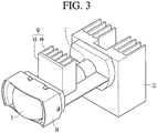
- FIG. 3 is a perspective view illustrating the lighting device for a vehicle according to the first embodiment of the present invention.
- the lighting device for a vehicle may include a lighting device 1 having a light source 10, a first reflecting unit 2, a lens 3 and a reflective fluorescent body 4.
- the lighting device for a vehicle may constitute a head lamp for a vehicle.
- the lighting device for a vehicle may be used as a high beam lighting device which generates a high beam or may be used as a low beam lighting device which generates a low beam.
- the lighting device 1 may emit beam to the first reflecting unit 2.
- the lighting device 1 is capable of emitting beam toward the lens 3 and the beam emitted toward the lens 3 transmits through the lens 3 and may be incident on the first reflecting unit 2.
- the lighting device 1 is capable of emitting beam toward a rear surface of the lens 3 and the beam which is incident on the rear surface of the lens 3 from the lighting device 1 transmits through the lens 3 and is incident on the first reflecting unit 2.
- the lighting device 1 may include the light source 10.
- the light source 10 receives the electric energy and may be converted the received electric energy into light energy.
- the light source 10 may be a light emitting source such as an ultra high pressure mercury lamp (UHV Lamp), a light emission diode (LED), and a laser diode.
- UHV Lamp ultra high pressure mercury lamp
- LED light emission diode
- laser diode a light emitting source
- a light source 10 preferably is a light source which is capable of irradiating with light from a long distance while having an excellent feature of straightness and high efficiency.
- the light source preferably is a laser diode.
- the laser diode which is a light source preferably is a laser diode which irradiates with a blue based laser beam having high efficiency.
- a heat radiating member 11 which radiates heat generated in the light source 10 is connected to the light source 10 as illustrated in FIG. 3 .
- the heat radiating member 11 may includes a contact plate which is in contact with the light source 10 and a heat radiating pin which is projected from the contact plate.
- the lighting device 1 may further include a reducer (not illustrated) which allows the diameter of the beam emitted from the light source 10 to be reduced and emits the beam toward the first reflecting unit 2, a reflecting member (not illustrated) which changes an optical path of the beam emitted from the light source 10, or the like.
- the beam emitted from the light source 10 may be emitted toward the first reflecting unit 2 after passing through the reducer.
- the beam emitted from the light source 10 is capable to being incident on the first reflecting unit 2.
- the beam emitted from the light source 10 is capable of being incident on the first reflecting unit 2 after the optical path is changed at the reflecting unit.
- the beam emitted from the light source 10 is capable to being incident on the first reflecting unit 2.
- the lighting device 1 includes the light source 10 and does not include the reducer (not illustrated) and the reflecting member (not illustrated) will be described.
- the scope of the present invention is not limited to this.
- the lens 3 may has a greater size than the sizes of the reflective fluorescent body 4 and the first reflecting unit 2.
- the reflective fluorescent body 4 and the first reflecting unit 2 are capable of being protected at the front side of the reflective fluorescent body 4.
- the lens 3 may include a front surface 31 and a rear surface 32.
- the lens 3 may further include a perimeter surface 33 according to a shape of the lens 3.
- the front side of the lens 3 can mean the front side of the front surface 31 of the lens and the rear side of the lens 3 can mean the rear side of the rear surface 32 of the lens.
- the lens 3 may be a meniscus lens of which the front surface 31 and the rear surface 32 have curvatures in the same directions with each other.
- the lens 3 may include a front surface (31) having a convex shape and a rear surface 32 having a concave shape. More specifically, the front surface 31 of the lens 3 may have a convex curved surface toward the front side and the rear surface 32 of the lens 3 may have having a recessed curved surface toward the front side. At this time, the inner area of the recessed curved surface which is the rear surface 32 of the lens 3 may means the rear side of the lens 3.
- the rear surface 32 of the lens 3 is a recessed curved surface, that is, a concave curved surface other than a flat surface
- an incident angle at which the beam reflected from the first reflecting unit 2 is incident on the rear surface 32 of the lens 3 may be decreased. Accordingly, an optical loss by reflection generated at the rear surface 32 of the lens 3 is reduced.
- the incident angle of beam which is reflected from the first reflecting unit 2 and passes through the rear surface 32 of the lens 3 to the reflective fluorescent body 4 is decreased and thus the optical efficiency is increased.
- the front surface 31 and/or the rear surface 32 of the lens 3 may be an aspheric surface.
- the rear surface 32 of the lens 3 may be a spherical surface having the same curvature in all the portions of the rear surface 32.
- the spherical surface has an advantages that manufacture thereof may be easy, the cost of the manufacture thereof may be low and the sensitivity to the point at which the beam reaches the lens 3 may be improved, compared to the aspheric surface.
- the curvature of the rear surface 32 of the lens 3 may be smaller than the curvature of the front surface 31 in order to condense the white based light emit from the reflective fluorescent body 4.
- the curvature of the rear surface 32 of the lens 3 may be a curvature that the beam reflected from the first reflecting unit 2 transmits through the rear surface 32 of the lens 3.
- the beam reflected from the first reflecting unit 2 transmits through the rear surface 32 of the lens 32 and then reaches the reflective fluorescent body 4. At this time, a portion of the beam reflected from the first reflecting unit 2 is not transmitted through the rear surface 32 of the lens 3 but may be reflected from the rear surface 32 of the lens 3.
- the optical loss may be generated. Further, there are concerns that the eyes of the human suffer injury or the eyesight of the human is damaged by the blue based beam of which the wavelength is not converted at the reflective fluorescent body 4 being capable of being emitted to the front side of the lighting device for a vehicle.
- the curvature of the rear surface 32 of the lens 3 is a curvature through which the beam reflected from the first reflecting unit 2 is transmitted through the rear surface 32 of the lens 3 so that the optical loss which is generated by the beam reflected from the first reflecting unit 2 being reflected at the rear surface 32 may be decreased.
- the curvature of the rear surface 32 of the lens 3 may be a curvature that an incident angle to the rear surface 32 of the lens 3 of the beam reflected from the first reflecting unit 2 is 0 degrees. At this time, when the beam reflected from the first reflecting unit 2 is transmitted through the rear surface 32 of the lens 3, a refraction may not occur. Further, when the reflected beam occurred from the first reflecting unit 2 is transmitted through the rear surface 32 of the lens 3, the reflection occurs from the rear surface 32 of the lens 3 may be minimized. Even if the reflection occurs from at the rear surface 32 of the lens 3, the beam may be reflected again from the first reflecting unit 2 and thus may be not emitted toward the front side of the lens 3.
- the lens 3 may include an optical axis X.
- the optical axis X of the lens 3 may be a rotational symmetrical axis or a center axis and may mean a straight line which passes through the center of the front surface 31 of the lens 3 and the center of the back surface 32 of the lens 3.
- the light source 10 may emit the beam in the direction parallel to the optical axis X of the lens 3.
- the lighting device for a vehicle may further include a projection lens 5 which is disposed on the front surface of the lens 3 for condensing light which is emitted from the front surface 31 of the lens 3.
- the projection lens 5 may have a greater size than the size of the lens 3.
- the optical axis of the projection lens 5 can be matched with the optical axis X of the lens 3.
- a plurality of projection lens 5 may be provided and the optical axes of the projection lens 5a and 5b may be matched with each other.
- the diameter of a second projection lens 5b disposed away from the lens 3 may be greater than the diameter of a first projection lens 5a disposed adjacent to the lens 3.
- the projection lens 5 may include a front surface 51, a rear surface 52, and a peripheral surface 53.
- the front surface 51 of the projection lens 5 may be a convex surface toward the front side.
- the rear surface 52 of the projection lens 5 may be a flat surface.
- the reflective fluorescent body 4 may be disposed on the rear side of the lens 3 and allows light which has the converted wavelength of the beam reflected from the first reflecting unit 2 to be emitted to the lens 3.
- the reflective fluorescent body 4 may be generated heat at the wavelength conversion of the light. Accordingly, the reflective fluorescent body 4 is preferably disposed to be spaced apart from the lens 3. The reflective fluorescent body 4 may be disposed on the rear side of the lens 3 to be spaced apart from the lens 3.
- the reflective fluorescent body 4 may be disposed on the rear side of the lens 3.
- the reflective fluorescent body 4 may be disposed to be faced the rear surface 32 of the lens 3 and may reflect light toward the rear surface 32 of the lens 3.
- the reflective fluorescent body 4 may be disposed on the optical axis X of the lens 3 to be spaced apart from the rear surface 32 of the lens 3.
- the reflective fluorescent body 4 may be capable of being eccentrically disposed with respect to the optical axis X of the lens 3 in addition to being disposed on the optical axis X of the lens 3.
- the efficiency is low because an area through which light reflected from the reflective fluorescent body 4 is transmitted is smaller than the area in a case where the reflective fluorescent body 4 is disposed on the optical axis X.
- the reflective fluorescent body 4 is preferably disposed to the optical axis X of the lens 3.
- assembly of the lens 3 may be improved at the time of the manufacturing of the lighting device for a vehicle by the reflective fluorescent body 4 being disposed on the optical axis X of the lens 3.
- a correct relative position between the lens 3 and the reflective fluorescent body 4 is set so that the beam emitted from the optical source 10 reach the reflective fluorescent body 4 and then the lens 3 and the reflective fluorescent body 4 have to be assembled to the correct relative position. In other words, the assembly of the lens may be difficult.
- the optical axis X may be matched with the center axis of the lens 3. Therefore, in this case, it is required only that the reflective fluorescent body 4 is disposed on the center axis of the lens 3 for assembly of the lens. In other words, the assembly of the lens may be relatively easy.
- the reflective fluorescent body may include a reflecting unit for reflecting light and a wavelength conversion layer which converts wavelength of light.
- the wavelength conversion layer faces the rear surface 32 of the lens 3 and the reflective unit may be disposed on the rear side of the wavelength conversion layer.
- the wavelength conversion layer may include a wavelength conversion film and may include an opto ceramic.
- the wavelength conversion layer is capable to converting the wavelength of the beam reflected from the first reflecting unit 2 in a state of being positioned at the front side of the reflecting unit.
- the wavelength conversion layer may be a wavelength conversion film which converts the blue based light into the yellow based light.
- the wavelength conversion layer may include an opto ceramic having yellow color.
- the reflecting unit may include a plate and a reflecting coating layer which is coated the outside surface of the plate.
- the plate is made of a metal.
- the reflecting unit may support the wavelength conversion layer and light transmitted through the wavelength conversion layer may be reflected toward the rear surface of the lens 3 by the reflecting unit.
- the blue based beam When the blue based beam is reflected from the first reflecting unit 2 and then is incident on the reflective fluorescent body 4, a portion of the blue based beam is surface-reflected on the surface of the wavelength conversion layer and the blue based beam which is incident on the inside of the wavelength conversion layer may be oscillated while being scattered in the inside of the wavelength conversion layer.
- the wavelength of a portion of the blue based light is converted into wavelength of the yellow based light and the wavelength of a portion of the blue based light may not be converted.
- the conversion rate may be changed according to the material of the fluorescent body, the rate containing YAG, or the like.
- the blue based light and the yellow based light in the inside of the wavelength conversion layer may be reflected to the front side of the wavelength conversion layer by the reflecting unit.
- the blue based light which is surface-reflected at the surface of the wavelength conversion layer and the blue and the yellow based lights emitted to the front side of the wavelength of the wavelength conversion layer are mixed with each other and thus may become white based light. Accordingly, the white based light is emitted in the front surface of the reflective fluorescent body 4. This white based light may be transmitted through the lens 3 and may be emitted toward the front side of the lens 3.
- the white based light emitted toward the front side in the reflective fluorescent body 4 radially spreads out toward the front side other than the laser beam having strong straightness.
- the lens 3 disposed on the front side of the reflective fluorescent body 4 and the projection lens 5 disposed on the front side of the lens 3 may perform a role condensing the white based light which is radiated.
- the width in the longitudinal direction of the lighting device for a vehicle is determined by the distance L1 between the reflective fluorescent body 4 and lens 3.
- the width in the longitudinal direction of the lighting device for a vehicle is lengthened and thus an optical efficiency thereof is reduced when the distance L1 between the reflective fluorescent body 4 and lens 3 is too long.
- the lens 3 may be damaged by heat of the reflective fluorescent body 4 when the distance L1 between the reflective fluorescent body 4 and the lens 3 is too short.
- the reflective fluorescent body 4 is closely disposed to the lens 3 within the range in which the damage of the lens 3 by heat is minimized.
- the heat radiating member 42 which assists to radiate heat of the reflective fluorescent body 4 may be disposed in the reflective fluorescent body 4.
- the heat radiating member 42 may includes a contact plate 43 which is in contact with the reflective fluorescent body 4, and a heat radiating pin 44 which is projected from the contact plate 43.
- the heat radiating member may be disposed on a side or a border of a transmissive fluorescent body, since a surface on which light is incident and the other surface from which light is emitted are different from each other. At this time, there is a problem which the heat radiation is not efficiently performed since the contact area between the heat radiating member and the transmissive fluorescent body is narrow.
- the contact plate 43 may be attached to the rear surface of the reflective unit to be surface-contacted since the surface on which light is incident and the surface from which is emitted are entirely the same in the reflective fluorescent body 4 according the present embodiment. At this time, the heat radiation is effectively performed since a contact area between contact plate 43 and the reflective fluorescent body 4 become wide.
- the first reflecting unit 2 may be provided to reflect the incident beam to the reflective fluorescent body 4.
- the first reflecting unit 2 be capable of being provided to lens 3 to be integrated with the lens 3 or be capable of being provided separately from the lens 3 spaced apart from the lens 3.
- the first reflecting unit 2 may be determined the position thereof according to an arrangement position of the reflective fluorescent body 4.
- the first reflecting unit 2 is positioned on the rear side of the lens 3 to be spaced apart from the lens 3, is provided on the rear surface of the lens 3, or is positioned on the front side of the lens 3 to be spaced apart from the lens 3.
- the first reflecting unit 2 allows the beam emitted from the light source 10 to be reflected to the reflective fluorescent body 4, in a state where the first reflecting unit 2 is provided on the rear side of the lens 3 to be spaced apart from the lens 3.
- the first reflecting unit 2 allows the beam emitted from the light source 10 to be reflected to the reflective fluorescent body 4, in a state where the first reflecting unit 2 is provided on the rear surface 32 of the lens 3 to be integrated with the lens 3.
- the first reflecting unit 2 allows the beam transmitted through the lens 3 after being emitted from light source 10 to be reflected to the lens 3 to be incident on the reflective fluorescent body 4, in a state where the first reflecting unit 2 is provided on the front surface 31 of the lens 3 to be integrated with the lens 3.
- the first reflecting unit 2 allows the beam transmitted through the lens 3 after being emitted from light source 10 to reflect to the lens 3 to be incident on the reflective fluorescent body 4, in a state where the first reflecting unit 2 is provided on the front side of the lens 3 to be spaced apart from the lens 3.
- the component number of the lighting device for a vehicle may be increased and the size of the lighting device for a vehicle is increased by the separation distance between the lens 3 and the first reflecting unit 2 from each other.
- the first reflecting unit 2 is provided in the front surface 31 or the rear surface 32 of the lens 3 to be integrated the first reflecting unit 2 and the lens 3 in order to minimize the component number of the lighting device for a vehicle and to be compact the lighting device for a vehicle.
- the first reflecting unit 2 is provided on the entire rear surface 32 of the lens 3 or the entire front surface 31 of the lens 3, the light of which wavelength is converted and which is reflected in the reflective fluorescent body 4 is all reflected to the rear side of the lens 3. Accordingly, light is not emitted to the front side of the lens 3 since the wavelength of the light is converted in the reflective fluorescent body 4.
- the first reflecting unit 2 is provided on a portion of the rear surface 32 of the lens 3 or a portion of the front surface 31 of the lens 3.
- the first reflecting unit 2 has a size that the lens 3 is capable of securing the sufficient light emitting area.
- the first reflecting unit 2 gets out of the optical axis X of the lens 3 and thus is disposed on the outside of the axis.
- the first reflecting unit 2 is disposed between the optical axis X of the lens 3 and the perimeter surface 33 of the lens 3.
- the first reflecting unit 2 may be provided on a portion area of the rear surface 32 of the lens 3 or a portion area of the front surface 31 of the lens 3.
- the first reflecting unit 4 may be provided to reflect the beam emitted from the light source 10 to the reflective fluorescent body 4.
- the first reflecting unit 2 may reflect the incident light to the rear side of the lens 3.
- the arrangement position of the first reflecting unit 2 is determined considering on the position relationship between the reflective fluorescent body 4 and the lens 3 and the curvature of a portion area of the front surface 31 or the rear surface 32 of the lens 3.
- the first reflecting unit 2 may be attached to the front surface 31 of the lens 3. At this time, the beam emitted from the light source 10 transmits through the rear surface 32 of the lens 3 and then reaches the first reflecting unit 2 and the beam reflected from the first reflecting unit 2 transmits through the rear surface 32 of the lens 3 again and then is incident on the reflective fluorescent body 4.
- the optical efficiency may be increased since the incident angle to the reflective fluorescent body 4 of the beam is reduced in a case where the first reflecting unit 2 is attached to the front surface 31 of the lens 3 than in a case where the first reflecting unit 2 is attached to the rear surface 32 of the lens 3.
- the wider light emitting area may be secured in a case where the first reflecting unit 2 is attached to the front surface 31 of the lens 3 than in a case where the first reflecting unit 2 is attached to the rear surface 32 of the lens 3 when the first reflecting units 2 have the same sizes with each other at the two cases described above.
- the first reflecting unit 2 may be provided in a partial area of the front surface 31 of the lens 3.
- the beam emitted from the light source 10 transmits through the lens 3 and then may be incident on the first reflecting unit 2.
- the beam reflected from the light source 2 transmits through the lens 3 and then is incident on the reflective fluorescent body 4.
- the light of which the wavelength is converted by the reflective fluorescent body 4 transmits through the lens 3 and then may be irradiated to the front side of the lens 3.
- the light is transmitted through the lens three times. More specifically, the beam emitted from the light source 10 transmits through the lens 3 and then is incident on the first reflecting unit 2. The beam reflected from the first reflecting unit 2 transmits through the lens 3 and then is incident on the reflective fluorescent body 4. The light of which wavelength is converted and reflected from the reflective fluorescent body 4 transmits through the lens 3 and then emitted to the front side of the lens 3.
- the lens 3 may be a three-path lens through which light transmits three times.
- the lighting device for a vehicle is capable of being made to be compact by this three-path lens.
- the lens 3 is the three-path lens
- the beam is not emitted to the front side of the lens 3 before the beam emitted from the light source 10 reaches the reflective fluorescent body 4.
- all the optical devices except for the first reflecting unit 2, for example, the lighting device 1, and the reflective fluorescent body 4 may be provided at the rear side of the lens 3.
- an additional optical component for being incident light on the reflective fluorescent body 4 may is not disposed on the front side which is spaced apart from the lens 3. Accordingly, arrangement of the optical components is easy.
- the manufacturing of the lighting device for a vehicle become easy, the replacement or the design change of the lighting device 1 to the reflective fluorescent body 4 also becomes easy, and a provision of an additional optical device such as the reflecting member to the lighting device 1 becomes easy.
- the lens 3 and the projection lens 5 may be disposed so that the distance between the lens 3 and the projection lens 5 is reduced, since an additional optical component that allows light to be incident on the reflective fluorescent body 4 in the front side spaced apart from the lens 3. Accordingly, the optical efficiency and the light collecting effect of the projection lens 5 may be increased.
- the first reflecting unit 2 is formed according to a concave front surface 31 in a portion of a concave front surface 31 of the lens 3 and the cross sectional shape of the first reflecting unit 2 may be formed as an arc-shape.
- the first reflecting unit 2 may be a round shape or a polygonal shape when viewing from the front side of the lens 3.
- the first reflecting unit 2 may be a concave mirror formed on the front surface 31 of the lens 3.
- the first reflecting unit 2 may have a convex front surface and a concave rear surface.
- the front surface of the first reflecting unit 2 may faces the projection lens 5.
- the first reflecting unit 2 may be projected by the lens 3 and the projection lens 5 between the lens 3 and the projection lens 5.
- the first reflecting unit 2 may be a coating layer coated at the position other than the optical axis X of the lens 3 of the front surface 31 of the lens 3.
- the first reflecting unit 2 may be a reflective sheet attached at the position other than the optical axis X of the lens 3 of the front surface 31 of the lens 3.
- the first reflecting unit 2 may be disposed on the position which gets out of an extension line W connecting the light source 10 and the reflective fluorescent body 4 so that the beam emitted toward the first reflective unit 2 from the light source 10 reaches the first reflective unit 2 without being blocked by the rear surface of the reflective fluorescent body 4.
- the reflective fluorescent body 4 is disposed on the optical axis X of the lens 3, the light source 10 gets out of the optical axis X of the lens 3 not to be disposed on the axis, and the light source 10 may emit beam in the direction parallel to the optical axis X of the lens 3. Further, the first reflecting unit 2 gets out of the optical axis X of the lens 3 not to be disposed on the axis so that the beam emitted from the light source 10 reach the first reflecting unit 2.
- the lighting device for a vehicle may further include a lens holder 58 which supports the lens 3 and the projection lens 5.
- the light source 10 emits the blue based beam and the reflective fluorescent body 4 converts the wavelength of the blue based light into the wavelength of the yellow based light.
- the beam B which is incident on the rear surface 32 of the lens 3 transmits through the lens 3 and may be incident on the first reflecting unit 2, and then may be reflected from the first reflecting unit 2 to the lens 3.
- the beam C reflected from the first reflecting unit 2 may be reflected in the direction toward the optical axis X of the lens 3 by the first reflecting unit 2 and may transmit through the rear surface 32 of the lens 3 and then may be refracted.
- the beam D transmitted through the rear surface of the lens 3 may be incident on the reflective fluorescent body 4.
- the wavelength of the beam which is incident on the reflective fluorescent body 4 may be converted by the reflective fluorescent body 4 and the white based light E may be reflected to the rear surface 32 of the lens 3 and may be collected while being transmitted through the lens 3 in the reflective fluorescent body 4.
- the white based light E may transmit through the front surface 31 of the lens 3 and then may be incident on the projection lens 5 through the rear surface 52 of the projection lens 5, may be collected at the projection lens 5 and then may be emitted parallel and thus this light F may be irradiated to the front side of a vehicle.
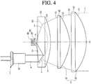
- FIG. 4 is a construction view illustrating a lighting device for a vehicle according to a second embodiment of the present invention.
- the lens 3 may be a meniscus lens.
- the first reflecting unit 2 may be attached on the rear surface 32 of the lens 3.
- the reflective fluorescent body 4 may be disposed on the center of the spherical surface on which the beam reflected from the first reflecting unit attached on the rear surface 32 is collected.
- the distance L1 between the lens 3 and the reflective fluorescent body 4 is increased and thus the optical efficiency may be decreased.
- the rear surface of the lens 3 may be a spherical surface or an aspheric surface.
- the beam A which is emitted from the light source 10 does not transmits through the lens 3 and is immediately incident on the first reflecting unit 2, and then is reflected from the first reflecting unit 2 toward the reflective fluorescent body 4.
- the beam D reflected from the first reflecting unit 2 may be reflected in the direction toward the optical axis X of the lens 3 by the first reflecting unit 2 and thus may be incident on the reflective fluorescent body 4.
- the wavelength of the beam which is incident on the reflective fluorescent body 4 may be converted by the reflective fluorescent body 4 and the white based light E may be reflected to the rear surface 32 of the lens 3 in the reflective fluorescent body 4.
- the white based light is condensed while transmitting through the lens 3.
- the white based light E may transmit through the front surface 31 of the lens 3 and then may be incident on the projection lens 5 through the rear surface 52 of the projection lens 5, may be condensed at the projection lens 5 and then may be emitted in parallel.
- This light F may be irradiated to the front side of a vehicle.
- the optical loss due to reflection which is capable of generating at the rear surface 32 of the lens 3 is not generated, since the beam emitted from the light source 10 is not transmits through the lens 3 and reaches the reflective fluorescent body 4.
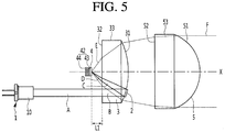
- FIG. 5 is a construction view illustrating a lighting device for a vehicle according to a third embodiment of the present invention.
- the front surface 31 of the lens 3 may have a convex curved surface toward the front side and the rear surface 32 of the lens 3 may have a flat surface.
- the first reflecting unit 2 may be provided on the front surface 31 of the lens 3. If the first reflecting unit 2 is provided on the rear surface 32 of the lens 3 which is a flat surface, the beam which is incident on the first reflecting unit 2 is not capable of being condensed.
- the optical loss which is generated at the air layer is reduced and thus the optical power may be relatively high. Accordingly, only one projection lens 5 may be provided.
- the processability thereof is excellent, manufacturing thereof is easy and cost thereof may be reduced. Further, comparing to the meniscus lens, the size of the lens 3 is decreased, the number of the projection lens 5 is decreased and thus the lighting device for a vehicle is capable of being to be compact.
- FIG. 6 is a construction view illustrating a lighting device for a vehicle according to a fourth embodiment of the present invention.
- the present invention may include a second reflective fluorescent body 6 which reflects a portion of the beam which is reflected from the reflective fluorescent body 4 to the lens 3 to the rear side of the lens 3. Since the other constructions and the effects other than the second reflecting unit 6 are the same or similar to the first embodiment to third embodiment of the present invention, the other constructions other than the second reflecting unit 6 use the same numerical references as the first embodiment to third embodiment of the present invention and their detailed description is omitted.
- the second reflecting unit 6 is connected with the first reflecting unit 2 and thus may constitute a single reflecting unit. However, preferably, in order to fully secure a light emitting area of the lens 3, the second reflecting unit 6 is provided to be spaced apart from the first reflecting unit 2 in the front surface 31 or the rear surface 32 of the lens 3.
- the light source 10 may be a laser diode and a blue based laser beam having a high efficiency may be irradiated, in a case where the light leakage phenomenon generates and thus the laser light is not converted into the white color light at the fluorescent body and is emitted to the front side of the lighting device for a vehicle, there is a concern that the eye of the person is damaged or eyesight is damaged.
- the second reflecting unit 6 is capable of reflecting the blue based beam which is surface-reflected without the wavelength converting at the reflective fluorescent body 4 to the rear side of the lens 3.
- the second reflecting unit 6 is capable of reflecting the blue based beam of which the wavelength is not converted and the white based light of which the wavelength is converted to the rear side of the lens 3. At this time, when the white based light is reflected to the rear side of the lens 3, the optical efficiency of the lighting device for a vehicle is reduced.
- the second reflecting unit 6 having a size and a position which sufficiently secure the optical emitting area of the lens 3 and is capable of reflecting the blue based beam surface reflected from the reflective fluorescent body 4 to the rear side of the lens 3 as much as possible is provided.
- the first reflecting unit 2 and the second reflecting unit 6 may be provided on the front surface 31 of the lens 3 as illustrated in the FIG. 6 , respectively, or may be provided on the rear surface 32 of the lens 3.
- the first reflecting unit 2 and the second reflecting unit 6 may have an arc shape as a cross-sectional shape on the convex front surface 31 of the lens 3, respectively.
- the first reflecting unit 2 and the second reflecting unit 6 may have a concave mirror formed along the front surface 31 of the lens 3 on the convex front surface 31 of the lens 3, respectively.
- the first reflecting unit 2 and the second reflecting unit 6 may be provided to be spaced apart with each other.
- the first reflecting unit 2 and the second reflecting unit 6 may be provided symmetrically relative to the optical axis X of the lens 3.
- the first reflecting unit 2 and the second reflecting unit 6 may be provided symmetrically to be a 180° phase difference to the front surface 31 of the lens 3.
- the first reflecting unit 2 may be provided on the left area of the front surface 31 of the lens 3
- the second reflecting unit 6 may be provided on the right area of the front surface 31 of the lens 3.
- the first reflecting unit 2 may be provided on the upper side area of the front surface 31 of the lens 3
- the second reflecting unit 6 may be provided on the lower side area of the front surface 31 of the lens 3.
- the first reflecting unit 2 and the second reflecting unit 6 may be provided at the same distance from the optical axis X of the lens with each other or at the different distance from the optical axis X of the lens with each other.
- the curvature of a portion thereof to which the first reflecting unit 2 and the second reflecting unit 6 is attached may be the same with each other.
- the first reflecting unit 2 and the second reflecting unit 6 is made of a reflective coating layer coated on the portion other than the optical axis X of the lens 3 of the front surface of the lens 3 or is made of a reflective seat attached to the portion other than the optical axis X of the lens 3 of the front surface of the lens 3, respectively.
- the first reflecting unit 2 provided on the front surface 31 of the lens 3 may reflect the beam which is emitted from the light source 10 and then is transmitted through the lens 3 to the reflective fluorescent body 4.
- the light which is reflected from the reflective fluorescent body 4 may be transmitted through the lens 3.
- a portion of light which is reflected from the reflective fluorescent body 4 to the lens 3 may be incident on the second reflecting unit 6.
- the light from the reflective fluorescent body 4 to the second reflecting unit 6 may be reflected in the rear side direction of the lens 3 by the second reflecting unit 6.
- the light G which is reflected in the rear side direction of the lens 3 by the second reflecting unit 6 is transmitted through the rear surface 32 of the lens and may be refracted.
- the light H which is reflected from the second reflecting unit 6 and then is transmitted through the rear surface of the lens 3 may be irradiated into the rear side of the lens 3.
- the second reflecting unit 6 may minimize the light leak phenomenon which may be generated when the beam which is surface-reflected without the wavelength conversion in the reflective fluorescent body 4 transmits through an area on which the second reflecting unit 6 of the lens 3 is formed.
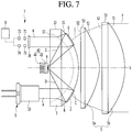
- FIG. 7 is a construction view illustrating an optical path of the lighting device for a vehicle according to a fifth embodiment of the present invention.
- the present embodiment may include a detecting unit 7 which detects light H reflected to the rear side of the lens 3 from the second reflecting unit 6, and a control unit 8 which controls the light source 10 according to the detection value of the detecting unit 7. Since the other constructions and the effects thereof other than the detecting unit 7 and the control unit 8 are the same or similar to the fourth embodiment of the present invention, the other constructions other than the detecting unit 7 and the control unit 8 use the same numerical references as the first embodiment to third embodiment of the present invention and their detailed description are omitted.
- the detecting unit 7 may be disposed on the rear side of the lens 3.
- the detecting unit 7 is disposed outside of the optical axis X of the lens 3.
- the detecting unit 7 may be disposed on the rear side of the area on which the second reflecting unit 6 of the lens 3 is attached.
- the detecting unit 7 may include a first filter 71 through which a blue light is transmitted, a first optical sensor 72 which detects light which transmits through the first filter 71, a second filter 73 which blocks the blue light, and a second optical sensor 74 which detects light which transmits through the second filter 73.
- the detecting unit 7 may further include a third filter 78 which is disposed on the front side of the first filter 71 and the second filter 73 and thus detects light which is towards the first filter 71 and the second filter 73.
- a third filter 78 which is disposed on the front side of the first filter 71 and the second filter 73 and thus detects light which is towards the first filter 71 and the second filter 73.
- the control unit 8 may allow the light source 10 to be turned off when the control unit 8 detects light which is more than the reference value in the first optical sensor 72.
- the control unit 8 may allow the light source 10 to be turned off when the control unit 8 detects light which is equal to and less than the reference value or does not detect light at the second optical sensor 74.
- the reflective fluorescent body 4 cannot convert the blue based light into the white based light.
- the light source 10 may be turned off in order not to emit the blue based light in the front side of the vehicle.
- the light which is less than the reference value is detected or does not detect light at the second optical sensor 74, it may be meant that the reflective fluorescent body 4 cannot normally functioned.
- the light source 10 may be turned off in order not to emit the blue based light in the front side of the vehicle.
Landscapes
- Engineering & Computer Science (AREA)
- General Engineering & Computer Science (AREA)
- Physics & Mathematics (AREA)
- Optics & Photonics (AREA)
- Mechanical Engineering (AREA)
- General Physics & Mathematics (AREA)
- Non-Portable Lighting Devices Or Systems Thereof (AREA)
- Microelectronics & Electronic Packaging (AREA)
Abstract
Description
- The present invention relates to a lighting device for a vehicle, and more specifically to a light device for a vehicle which at least one reflects light irradiated from a light source and then projects the light to outside.
- A lighting device such as a lamp which causes a driver to secure visibility or can inform the outside of the current running state of the vehicle by increasing intensity of the illumination of the surrounding of the vehicle during running of the vehicle is installed in a vehicle.
- The lighting device for a vehicle installed in the vehicle may be include a head lamp which irradiates light to the front of the vehicle and a rear lamp which displays the heading direction of the vehicle, indicates whether or not the brake operation, or the like at the rear of the vehicle.
- The lighting device for a vehicle may form a low beam or a high beam for securing visibility of a driver at the time of night driving. Recently, use of an LED which has a high power efficiency and a long service life is gradually increased. In addition, it is possible to use a laser diode having a long irradiation distance.
- An objective of the present invention is to provide a lighting device for a vehicle which is capable of minimizing the number of components and manufacturing to be compact.
- A lighting device for a vehicle according to an embodiment of the present invention includes a light source; a first reflecting unit which reflects beam emitted from the light source; a lens in which the first reflecting unit is provided on a partial area of a surface thereof; and a reflective fluorescent body which converts a wavelength of light reflected from the first reflecting unit and then reflects the light into the lens.
- The reflective fluorescent body may be disposed on the rear side of the lens and faces a rear surface of the lens.
- The first reflecting unit may be disposed at a position away from, or offset with respect to, an extension line connecting the light source and the reflective fluorescent body.
- The rear surface of the lens may have a concave shape and the front surface of the lens may have a convex shape.
- The first reflecting unit may be provided in the rear surface of the lens and the rear surface of the lens may be an aspheric surface.
- The first reflecting unit may be provided in the front surface of the lens.
- The rear surface of the lens may be a spherical surface.
- A curvature of the rear surface of the lens may be less than a curvature of the front surface of the lens.
- The curvature of the rear surface of the lens may be a curvature through which the light reflected from the first reflecting unit is transmitted.
- The cross sectional shape of the first reflecting unit may be an arc shape.
- The first reflecting unit may be a concave mirror which is formed in the surface of the lens.
- The light source may emit light in a direction parallel to the optical axis of the lens. The reflective fluorescent body may be disposed on the optical axis of the lens.
- The light source may get out of the optical axis of the lens and thus may be disposed the outside of the axis.
- The reflective fluorescent body may include a reflecting unit for reflecting light and a wavelength conversion layer which converts wavelength of light.
- The reflective fluorescent body may further include a heat radiating member for cooling heat.
- The lighting device for a vehicle according to an embodiment of the present invention may further include a second reflecting unit that reflects light reflected from the reflective fluorescent body to the rear side of the lens on the surface of the lens.
- The rear surface of the lens may be a flat surface, the front surface of the lens may be a convex surface, and the first reflecting unit may be provided on the front surface of the lens.
- In the lighting device for a vehicle according to the embodiment of the present invention, an additional optical component for being incident the light on the reflective fluorescent body is not disposed in the front side spaced apart from the lens.
- Accordingly, the optical components are easily disposed and number of the component is minimized and thus the lighting device may be to be compact by the first reflecting unit being provided in a partial area of the surface of the lens.
-
-
FIG. 1 is a construction view illustrating a lighting device for a vehicle according to a first embodiment of the present invention, -
FIG. 2 is a construction view illustrating an optical path of the lighting device for a vehicle according to the first embodiment of the present invention, -
FIG. 3 is a perspective view illustrating the lighting device for a vehicle according to the first embodiment of the present invention, -
FIG. 4 is a construction view illustrating a lighting device for a vehicle according to a second embodiment of the present invention, -
FIG. 5 is a construction view illustrating a lighting device for a vehicle according to a third embodiment of the present invention, -
FIG. 6 is a construction view illustrating an optical path of the lighting device for a vehicle according to a fourth embodiment of the present invention, and -
FIG. 7 is a construction view illustrating an optical path of the lighting device for a vehicle according to a fifth embodiment of the present invention. - Embodiments described in the present specification will be described with reference to construction drawings and/or schematic drawings which are ideally illustrated drawings. Accordingly, the constructions of the illustrated drawings may be modified by a manufacturing technique, tolerance or the like.
- Further, each component illustrated in the respective drawings of the present invention can be slightly enlarged or reduced in consideration of the convenience of the description. The optical paths shown in the drawings may be illustrated in a somewhat simplified manner in consideration of the convenience of explanation.
- Hereinafter, specific embodiments of the present invention will be described in detail with reference to the drawings.
-
FIG. 1 is a construction view illustrating a lighting device for a vehicle according to a first embodiment of the present invention,FIG. 2 is a construction view illustrating an optical path of the lighting device for a vehicle according to the first embodiment of the present invention, andFIG. 3 is a perspective view illustrating the lighting device for a vehicle according to the first embodiment of the present invention. - The lighting device for a vehicle may include a
lighting device 1 having alight source 10, a first reflectingunit 2, alens 3 and a reflectivefluorescent body 4. - The lighting device for a vehicle may constitute a head lamp for a vehicle. The lighting device for a vehicle may be used as a high beam lighting device which generates a high beam or may be used as a low beam lighting device which generates a low beam.
- According to an embodiment of the present invention, the
lighting device 1 may emit beam to the first reflectingunit 2. Thelighting device 1 is capable of emitting beam toward thelens 3 and the beam emitted toward thelens 3 transmits through thelens 3 and may be incident on the first reflectingunit 2. - The
lighting device 1 is capable of emitting beam toward a rear surface of thelens 3 and the beam which is incident on the rear surface of thelens 3 from thelighting device 1 transmits through thelens 3 and is incident on the first reflectingunit 2. - The
lighting device 1 may include thelight source 10. Thelight source 10 receives the electric energy and may be converted the received electric energy into light energy. Thelight source 10 may be a light emitting source such as an ultra high pressure mercury lamp (UHV Lamp), a light emission diode (LED), and a laser diode. - A
light source 10 preferably is a light source which is capable of irradiating with light from a long distance while having an excellent feature of straightness and high efficiency. Also, the light source preferably is a laser diode. The laser diode which is a light source preferably is a laser diode which irradiates with a blue based laser beam having high efficiency. - A
heat radiating member 11 which radiates heat generated in thelight source 10 is connected to thelight source 10 as illustrated inFIG. 3 . Theheat radiating member 11 may includes a contact plate which is in contact with thelight source 10 and a heat radiating pin which is projected from the contact plate. - The
lighting device 1 may further include a reducer (not illustrated) which allows the diameter of the beam emitted from thelight source 10 to be reduced and emits the beam toward the first reflectingunit 2, a reflecting member (not illustrated) which changes an optical path of the beam emitted from thelight source 10, or the like. - In a case where the
lighting device 1 includes both thelight source 10 and the reducer, the beam emitted from thelight source 10 may be emitted toward the first reflectingunit 2 after passing through the reducer. In a case where thelighting device 1 includes thelight source 10 and does not include the reducer, the beam emitted from thelight source 10 is capable to being incident on the first reflectingunit 2. - In a case where the
lighting device 1 includes both thelight source 10 and the reducer, the beam emitted from thelight source 10 is capable of being incident on the first reflectingunit 2 after the optical path is changed at the reflecting unit. In a case where thelighting device 1 includes thelight source 10 and does not include the reflecting member, the beam emitted from thelight source 10 is capable to being incident on the first reflectingunit 2. - Hereinafter, a case where the
lighting device 1 includes thelight source 10 and does not include the reducer (not illustrated) and the reflecting member (not illustrated) will be described. However, the scope of the present invention is not limited to this. - The
lens 3 may has a greater size than the sizes of the reflectivefluorescent body 4 and the first reflectingunit 2. The reflectivefluorescent body 4 and the first reflectingunit 2 are capable of being protected at the front side of the reflectivefluorescent body 4. - The
lens 3 may include afront surface 31 and arear surface 32. Thelens 3 may further include aperimeter surface 33 according to a shape of thelens 3. The front side of thelens 3 can mean the front side of thefront surface 31 of the lens and the rear side of thelens 3 can mean the rear side of therear surface 32 of the lens. - The
lens 3 may be a meniscus lens of which thefront surface 31 and therear surface 32 have curvatures in the same directions with each other. - The
lens 3 may include a front surface (31) having a convex shape and arear surface 32 having a concave shape. More specifically, thefront surface 31 of thelens 3 may have a convex curved surface toward the front side and therear surface 32 of thelens 3 may have having a recessed curved surface toward the front side. At this time, the inner area of the recessed curved surface which is therear surface 32 of thelens 3 may means the rear side of thelens 3. - In a case where the
rear surface 32 of thelens 3 is a recessed curved surface, that is, a concave curved surface other than a flat surface, an incident angle at which the beam reflected from the first reflectingunit 2 is incident on therear surface 32 of thelens 3 may be decreased. Accordingly, an optical loss by reflection generated at therear surface 32 of thelens 3 is reduced. In addition, the incident angle of beam which is reflected from the first reflectingunit 2 and passes through therear surface 32 of thelens 3 to the reflectivefluorescent body 4 is decreased and thus the optical efficiency is increased. - The
front surface 31 and/or therear surface 32 of thelens 3 may be an aspheric surface. - The
rear surface 32 of thelens 3 may be a spherical surface having the same curvature in all the portions of therear surface 32. The spherical surface has an advantages that manufacture thereof may be easy, the cost of the manufacture thereof may be low and the sensitivity to the point at which the beam reaches thelens 3 may be improved, compared to the aspheric surface. - The curvature of the
rear surface 32 of the lens 3may be smaller than the curvature of thefront surface 31 in order to condense the white based light emit from the reflectivefluorescent body 4. - The curvature of the
rear surface 32 of thelens 3 may be a curvature that the beam reflected from the first reflectingunit 2 transmits through therear surface 32 of thelens 3. - In a case where the first reflecting
unit 2 is provided on thefront surface 31 of thelens 3, the beam reflected from the first reflectingunit 2 transmits through therear surface 32 of thelens 32 and then reaches the reflectivefluorescent body 4. At this time, a portion of the beam reflected from the first reflectingunit 2 is not transmitted through therear surface 32 of thelens 3 but may be reflected from therear surface 32 of thelens 3. - In this case, the optical loss may be generated. Further, there are concerns that the eyes of the human suffer injury or the eyesight of the human is damaged by the blue based beam of which the wavelength is not converted at the reflective
fluorescent body 4 being capable of being emitted to the front side of the lighting device for a vehicle. - Accordingly, it is preferable that the curvature of the
rear surface 32 of thelens 3 is a curvature through which the beam reflected from the first reflectingunit 2 is transmitted through therear surface 32 of thelens 3 so that the optical loss which is generated by the beam reflected from the first reflectingunit 2 being reflected at therear surface 32 may be decreased. - More preferably, the curvature of the
rear surface 32 of thelens 3 may be a curvature that an incident angle to therear surface 32 of thelens 3 of the beam reflected from the first reflectingunit 2 is 0 degrees. At this time, when the beam reflected from the first reflectingunit 2 is transmitted through therear surface 32 of thelens 3, a refraction may not occur. Further, when the reflected beam occurred from the first reflectingunit 2 is transmitted through therear surface 32 of thelens 3, the reflection occurs from therear surface 32 of thelens 3 may be minimized. Even if the reflection occurs from at therear surface 32 of thelens 3, the beam may be reflected again from the first reflectingunit 2 and thus may be not emitted toward the front side of thelens 3. - The
lens 3 may include an optical axis X. Here, the optical axis X of thelens 3 may be a rotational symmetrical axis or a center axis and may mean a straight line which passes through the center of thefront surface 31 of thelens 3 and the center of theback surface 32 of thelens 3. - At this time, the
light source 10 may emit the beam in the direction parallel to the optical axis X of thelens 3. - The lighting device for a vehicle may further include a
projection lens 5 which is disposed on the front surface of thelens 3 for condensing light which is emitted from thefront surface 31 of thelens 3. - The
projection lens 5 may have a greater size than the size of thelens 3. - The optical axis of the
projection lens 5 can be matched with the optical axis X of thelens 3. - In order to improve the effect of condensing light, a plurality of
projection lens 5 may be provided and the optical axes of theprojection lens - In order to condense the spreading out light, the diameter of a
second projection lens 5b disposed away from thelens 3 may be greater than the diameter of afirst projection lens 5a disposed adjacent to thelens 3. - The
projection lens 5 may include afront surface 51, arear surface 52, and aperipheral surface 53. Thefront surface 51 of theprojection lens 5 may be a convex surface toward the front side. Therear surface 52 of theprojection lens 5 may be a flat surface. - The reflective
fluorescent body 4 may be disposed on the rear side of thelens 3 and allows light which has the converted wavelength of the beam reflected from the first reflectingunit 2 to be emitted to thelens 3. - The reflective
fluorescent body 4 may be generated heat at the wavelength conversion of the light. Accordingly, the reflectivefluorescent body 4 is preferably disposed to be spaced apart from thelens 3. The reflectivefluorescent body 4 may be disposed on the rear side of thelens 3 to be spaced apart from thelens 3. - The reflective
fluorescent body 4 may be disposed on the rear side of thelens 3. - The reflective
fluorescent body 4 may be disposed to be faced therear surface 32 of thelens 3 and may reflect light toward therear surface 32 of thelens 3. - The reflective
fluorescent body 4 may be disposed on the optical axis X of thelens 3 to be spaced apart from therear surface 32 of thelens 3. - The reflective
fluorescent body 4 may be capable of being eccentrically disposed with respect to the optical axis X of thelens 3 in addition to being disposed on the optical axis X of thelens 3. - However, in this case, the efficiency is low because an area through which light reflected from the reflective
fluorescent body 4 is transmitted is smaller than the area in a case where the reflectivefluorescent body 4 is disposed on the optical axis X. In other words, the reflectivefluorescent body 4 is preferably disposed to the optical axis X of thelens 3. - In addition, assembly of the
lens 3 may be improved at the time of the manufacturing of the lighting device for a vehicle by the reflectivefluorescent body 4 being disposed on the optical axis X of thelens 3. - More specifically, if the reflective
fluorescent body 4 is not disposed on the optical axis X of thelens 3, a correct relative position between thelens 3 and the reflectivefluorescent body 4 is set so that the beam emitted from theoptical source 10 reach the reflectivefluorescent body 4 and then thelens 3 and the reflectivefluorescent body 4 have to be assembled to the correct relative position. In other words, the assembly of the lens may be difficult. - Contrary to this, in a case where the reflective
fluorescent body 4 is disposed on the optical axis X of thelens 3, the optical axis X may be matched with the center axis of thelens 3. Therefore, in this case, it is required only that the reflectivefluorescent body 4 is disposed on the center axis of thelens 3 for assembly of the lens. In other words, the assembly of the lens may be relatively easy. - The reflective fluorescent body may include a reflecting unit for reflecting light and a wavelength conversion layer which converts wavelength of light.
- The wavelength conversion layer faces the
rear surface 32 of thelens 3 and the reflective unit may be disposed on the rear side of the wavelength conversion layer. - The wavelength conversion layer may include a wavelength conversion film and may include an opto ceramic. The wavelength conversion layer is capable to converting the wavelength of the beam reflected from the first reflecting
unit 2 in a state of being positioned at the front side of the reflecting unit. - When the blue based beam is incident from the outside, the wavelength conversion layer may be a wavelength conversion film which converts the blue based light into the yellow based light. The wavelength conversion layer may include an opto ceramic having yellow color.
- The reflecting unit may include a plate and a reflecting coating layer which is coated the outside surface of the plate. The plate is made of a metal.
- The reflecting unit may support the wavelength conversion layer and light transmitted through the wavelength conversion layer may be reflected toward the rear surface of the
lens 3 by the reflecting unit. - When the blue based beam is reflected from the first reflecting
unit 2 and then is incident on the reflectivefluorescent body 4, a portion of the blue based beam is surface-reflected on the surface of the wavelength conversion layer and the blue based beam which is incident on the inside of the wavelength conversion layer may be oscillated while being scattered in the inside of the wavelength conversion layer. - The wavelength of a portion of the blue based light is converted into wavelength of the yellow based light and the wavelength of a portion of the blue based light may not be converted. The conversion rate may be changed according to the material of the fluorescent body, the rate containing YAG, or the like. The blue based light and the yellow based light in the inside of the wavelength conversion layer may be reflected to the front side of the wavelength conversion layer by the reflecting unit.
- The blue based light which is surface-reflected at the surface of the wavelength conversion layer and the blue and the yellow based lights emitted to the front side of the wavelength of the wavelength conversion layer are mixed with each other and thus may become white based light. Accordingly, the white based light is emitted in the front surface of the reflective
fluorescent body 4. This white based light may be transmitted through thelens 3 and may be emitted toward the front side of thelens 3. - At this time, the white based light emitted toward the front side in the reflective
fluorescent body 4 radially spreads out toward the front side other than the laser beam having strong straightness. Thelens 3 disposed on the front side of the reflectivefluorescent body 4 and theprojection lens 5 disposed on the front side of thelens 3 may perform a role condensing the white based light which is radiated. - The width in the longitudinal direction of the lighting device for a vehicle is determined by the distance L1 between the reflective
fluorescent body 4 andlens 3. - The width in the longitudinal direction of the lighting device for a vehicle is lengthened and thus an optical efficiency thereof is reduced when the distance L1 between the reflective
fluorescent body 4 andlens 3 is too long. Thelens 3 may be damaged by heat of the reflectivefluorescent body 4 when the distance L1 between the reflectivefluorescent body 4 and thelens 3 is too short. - Accordingly, preferably, the reflective
fluorescent body 4 is closely disposed to thelens 3 within the range in which the damage of thelens 3 by heat is minimized. - The
heat radiating member 42 which assists to radiate heat of the reflectivefluorescent body 4 may be disposed in the reflectivefluorescent body 4. Theheat radiating member 42 may includes acontact plate 43 which is in contact with the reflectivefluorescent body 4, and aheat radiating pin 44 which is projected from thecontact plate 43. - In a case of a transmissive fluorescent body, the heat radiating member may be disposed on a side or a border of a transmissive fluorescent body, since a surface on which light is incident and the other surface from which light is emitted are different from each other. At this time, there is a problem which the heat radiation is not efficiently performed since the contact area between the heat radiating member and the transmissive fluorescent body is narrow.
- The
contact plate 43 may be attached to the rear surface of the reflective unit to be surface-contacted since the surface on which light is incident and the surface from which is emitted are entirely the same in the reflectivefluorescent body 4 according the present embodiment. At this time, the heat radiation is effectively performed since a contact area betweencontact plate 43 and the reflectivefluorescent body 4 become wide. - Meanwhile, the first reflecting
unit 2 may be provided to reflect the incident beam to the reflectivefluorescent body 4. - The first reflecting
unit 2 be capable of being provided tolens 3 to be integrated with thelens 3 or be capable of being provided separately from thelens 3 spaced apart from thelens 3. - The first reflecting
unit 2 may be determined the position thereof according to an arrangement position of the reflectivefluorescent body 4. In a case where the reflectivefluorescent body 4 is disposed on the rear side of thelens 3, the first reflectingunit 2 is positioned on the rear side of thelens 3 to be spaced apart from thelens 3, is provided on the rear surface of thelens 3, or is positioned on the front side of thelens 3 to be spaced apart from thelens 3. - The first reflecting
unit 2 allows the beam emitted from thelight source 10 to be reflected to the reflectivefluorescent body 4, in a state where the first reflectingunit 2 is provided on the rear side of thelens 3 to be spaced apart from thelens 3. - The first reflecting
unit 2 allows the beam emitted from thelight source 10 to be reflected to the reflectivefluorescent body 4, in a state where the first reflectingunit 2 is provided on therear surface 32 of thelens 3 to be integrated with thelens 3. - The first reflecting
unit 2 allows the beam transmitted through thelens 3 after being emitted fromlight source 10 to be reflected to thelens 3 to be incident on the reflectivefluorescent body 4, in a state where the first reflectingunit 2 is provided on thefront surface 31 of thelens 3 to be integrated with thelens 3. - The first reflecting
unit 2 allows the beam transmitted through thelens 3 after being emitted fromlight source 10 to reflect to thelens 3 to be incident on the reflectivefluorescent body 4, in a state where the first reflectingunit 2 is provided on the front side of thelens 3 to be spaced apart from thelens 3. - In a case where the first reflecting
unit 2 is provided the rear side or the front side of thelens 3 to be spaced apart fromlens 3, the component number of the lighting device for a vehicle may be increased and the size of the lighting device for a vehicle is increased by the separation distance between thelens 3 and the first reflectingunit 2 from each other. - Preferably, the first reflecting
unit 2 is provided in thefront surface 31 or therear surface 32 of thelens 3 to be integrated the first reflectingunit 2 and thelens 3 in order to minimize the component number of the lighting device for a vehicle and to be compact the lighting device for a vehicle. - In a case where the first reflecting
unit 2 is provided on the entirerear surface 32 of thelens 3 or the entirefront surface 31 of thelens 3, the light of which wavelength is converted and which is reflected in the reflectivefluorescent body 4 is all reflected to the rear side of thelens 3. Accordingly, light is not emitted to the front side of thelens 3 since the wavelength of the light is converted in the reflectivefluorescent body 4. - In other words, preferably, the first reflecting
unit 2 is provided on a portion of therear surface 32 of thelens 3 or a portion of thefront surface 31 of thelens 3. Preferably, the first reflectingunit 2 has a size that thelens 3 is capable of securing the sufficient light emitting area. - Preferably, the first reflecting
unit 2 gets out of the optical axis X of thelens 3 and thus is disposed on the outside of the axis. Preferably, the first reflectingunit 2 is disposed between the optical axis X of thelens 3 and theperimeter surface 33 of thelens 3. - The first reflecting
unit 2 may be provided on a portion area of therear surface 32 of thelens 3 or a portion area of thefront surface 31 of thelens 3. The first reflectingunit 4 may be provided to reflect the beam emitted from thelight source 10 to the reflectivefluorescent body 4. - The first reflecting
unit 2 may reflect the incident light to the rear side of thelens 3. - Preferably, the arrangement position of the first reflecting
unit 2 is determined considering on the position relationship between the reflectivefluorescent body 4 and thelens 3 and the curvature of a portion area of thefront surface 31 or therear surface 32 of thelens 3. - In the present embodiment, the first reflecting
unit 2 may be attached to thefront surface 31 of thelens 3. At this time, the beam emitted from thelight source 10 transmits through therear surface 32 of thelens 3 and then reaches the first reflectingunit 2 and the beam reflected from the first reflectingunit 2 transmits through therear surface 32 of thelens 3 again and then is incident on the reflectivefluorescent body 4. - The optical efficiency may be increased since the incident angle to the reflective
fluorescent body 4 of the beam is reduced in a case where the first reflectingunit 2 is attached to thefront surface 31 of thelens 3 than in a case where the first reflectingunit 2 is attached to therear surface 32 of thelens 3. - The wider light emitting area may be secured in a case where the first reflecting
unit 2 is attached to thefront surface 31 of thelens 3 than in a case where the first reflectingunit 2 is attached to therear surface 32 of thelens 3 when the first reflectingunits 2 have the same sizes with each other at the two cases described above. - In other words, the first reflecting
unit 2 may be provided in a partial area of thefront surface 31 of thelens 3. The beam emitted from thelight source 10 transmits through thelens 3 and then may be incident on the first reflectingunit 2. The beam reflected from thelight source 2 transmits through thelens 3 and then is incident on the reflectivefluorescent body 4. The light of which the wavelength is converted by the reflectivefluorescent body 4 transmits through thelens 3 and then may be irradiated to the front side of thelens 3. - In a case where the first reflecting
unit 2 is attached to thefront surface 31 of thelens 3, the light is transmitted through the lens three times. More specifically, the beam emitted from thelight source 10 transmits through thelens 3 and then is incident on the first reflectingunit 2. The beam reflected from the first reflectingunit 2 transmits through thelens 3 and then is incident on the reflectivefluorescent body 4. The light of which wavelength is converted and reflected from the reflectivefluorescent body 4 transmits through thelens 3 and then emitted to the front side of thelens 3. - Accordingly, the
lens 3 may be a three-path lens through which light transmits three times. The lighting device for a vehicle is capable of being made to be compact by this three-path lens. - In a case where the
lens 3 is the three-path lens, the beam is not emitted to the front side of thelens 3 before the beam emitted from thelight source 10 reaches the reflectivefluorescent body 4. Accordingly, all the optical devices except for the first reflectingunit 2, for example, thelighting device 1, and the reflectivefluorescent body 4 may be provided at the rear side of thelens 3. - More specifically, an additional optical component for being incident light on the reflective
fluorescent body 4 may is not disposed on the front side which is spaced apart from thelens 3. Accordingly, arrangement of the optical components is easy. - In other words, the manufacturing of the lighting device for a vehicle become easy, the replacement or the design change of the
lighting device 1 to the reflectivefluorescent body 4 also becomes easy, and a provision of an additional optical device such as the reflecting member to thelighting device 1 becomes easy. - In addition, the
lens 3 and theprojection lens 5 may be disposed so that the distance between thelens 3 and theprojection lens 5 is reduced, since an additional optical component that allows light to be incident on the reflectivefluorescent body 4 in the front side spaced apart from thelens 3. Accordingly, the optical efficiency and the light collecting effect of theprojection lens 5 may be increased. - The first reflecting
unit 2 is formed according to a concavefront surface 31 in a portion of a concavefront surface 31 of thelens 3 and the cross sectional shape of the first reflectingunit 2 may be formed as an arc-shape. The first reflectingunit 2 may be a round shape or a polygonal shape when viewing from the front side of thelens 3. - The first reflecting
unit 2 may be a concave mirror formed on thefront surface 31 of thelens 3. The first reflectingunit 2 may have a convex front surface and a concave rear surface. - The front surface of the first reflecting
unit 2 may faces theprojection lens 5. The first reflectingunit 2 may be projected by thelens 3 and theprojection lens 5 between thelens 3 and theprojection lens 5. - The first reflecting
unit 2 may be a coating layer coated at the position other than the optical axis X of thelens 3 of thefront surface 31 of thelens 3. - The first reflecting
unit 2 may be a reflective sheet attached at the position other than the optical axis X of thelens 3 of thefront surface 31 of thelens 3. - The first reflecting
unit 2 may be disposed on the position which gets out of an extension line W connecting thelight source 10 and the reflectivefluorescent body 4 so that the beam emitted toward the firstreflective unit 2 from thelight source 10 reaches the firstreflective unit 2 without being blocked by the rear surface of the reflectivefluorescent body 4. - Preferably, the reflective
fluorescent body 4 is disposed on the optical axis X of thelens 3, thelight source 10 gets out of the optical axis X of thelens 3 not to be disposed on the axis, and thelight source 10 may emit beam in the direction parallel to the optical axis X of thelens 3. Further, the first reflectingunit 2 gets out of the optical axis X of thelens 3 not to be disposed on the axis so that the beam emitted from thelight source 10 reach the first reflectingunit 2. - Further, the lighting device for a vehicle may further include a
lens holder 58 which supports thelens 3 and theprojection lens 5. - Hereinafter, reference numeral to refer to the illustrated light on each path is for ease of understanding, the reference numeral does not refer to the component of the invention or do not limit the scope of the invention.
- Hereinafter, as an example, it is described that the
light source 10 emits the blue based beam and the reflectivefluorescent body 4 converts the wavelength of the blue based light into the wavelength of the yellow based light. - With reference to
FIG. 2 , an operation of the present invention as in the present embodiment will be described as follow: - First, when the
light source 10 turns on, the blue based beam A may be emitted from thelight source 10 and the beam may be incident on therear surface 32 of thelens 3 parallel to the optical axis X of thelens 3. - The beam B which is incident on the
rear surface 32 of thelens 3 transmits through thelens 3 and may be incident on the first reflectingunit 2, and then may be reflected from the first reflectingunit 2 to thelens 3. - The beam C reflected from the first reflecting
unit 2 may be reflected in the direction toward the optical axis X of thelens 3 by the first reflectingunit 2 and may transmit through therear surface 32 of thelens 3 and then may be refracted. - The beam D transmitted through the rear surface of the
lens 3 may be incident on the reflectivefluorescent body 4. - The wavelength of the beam which is incident on the reflective
fluorescent body 4 may be converted by the reflectivefluorescent body 4 and the white based light E may be reflected to therear surface 32 of thelens 3 and may be collected while being transmitted through thelens 3 in the reflectivefluorescent body 4. The white based light E may transmit through thefront surface 31 of thelens 3 and then may be incident on theprojection lens 5 through therear surface 52 of theprojection lens 5, may be collected at theprojection lens 5 and then may be emitted parallel and thus this light F may be irradiated to the front side of a vehicle. -
FIG. 4 is a construction view illustrating a lighting device for a vehicle according to a second embodiment of the present invention. - Hereinafter, the detailed description to the same or the similar construction as the construction described above will be omitted. Accordingly, only different construction from the construction described above will be described.
- According to the present embodiment, the
lens 3 may be a meniscus lens. At this time, the first reflectingunit 2 may be attached on therear surface 32 of thelens 3. - When the
rear surface 32 of thelens 3 has a spherical surface, since a focus on which the reflected beam from the spherical surface is collected becomes a center of the spherical surface, the reflectivefluorescent body 4 may be disposed on the center of the spherical surface on which the beam reflected from the first reflecting unit attached on therear surface 32 is collected. In this case, the distance L1 between thelens 3 and the reflectivefluorescent body 4 is increased and thus the optical efficiency may be decreased. Accordingly, preferably, the rear surface of thelens 3 may be a spherical surface or an aspheric surface. - With reference to
FIG. 4 , an operation of the present embodiment having the conFIGuration as above will be described as follow: - First, when the
light source 10 turns on, the blue based beam A may be emitted from thelight source 10 and the beam may be incident on the first reflectingunit 2 parallel to the optical axis X of thelens 3. - The beam A which is emitted from the
light source 10 does not transmits through thelens 3 and is immediately incident on the first reflectingunit 2, and then is reflected from the first reflectingunit 2 toward the reflectivefluorescent body 4. - The beam D reflected from the first reflecting
unit 2 may be reflected in the direction toward the optical axis X of thelens 3 by the first reflectingunit 2 and thus may be incident on the reflectivefluorescent body 4. - The wavelength of the beam which is incident on the reflective
fluorescent body 4 may be converted by the reflectivefluorescent body 4 and the white based light E may be reflected to therear surface 32 of thelens 3 in the reflectivefluorescent body 4. The white based light is condensed while transmitting through thelens 3. - The white based light E may transmit through the
front surface 31 of thelens 3 and then may be incident on theprojection lens 5 through therear surface 52 of theprojection lens 5, may be condensed at theprojection lens 5 and then may be emitted in parallel. This light F may be irradiated to the front side of a vehicle. - According to the present invention, the optical loss due to reflection which is capable of generating at the
rear surface 32 of thelens 3 is not generated, since the beam emitted from thelight source 10 is not transmits through thelens 3 and reaches the reflectivefluorescent body 4. -
FIG. 5 is a construction view illustrating a lighting device for a vehicle according to a third embodiment of the present invention. - Hereinafter, the detailed description to the same or the similar construction as the construction described above will be omitted. Accordingly, only different construction from the construction described above will be described.
- In the present embodiment, the
front surface 31 of thelens 3 may have a convex curved surface toward the front side and therear surface 32 of thelens 3 may have a flat surface. At this time, the first reflectingunit 2 may be provided on thefront surface 31 of thelens 3. If the first reflectingunit 2 is provided on therear surface 32 of thelens 3 which is a flat surface, the beam which is incident on the first reflectingunit 2 is not capable of being condensed. - In a case where the
rear surface 32 of thelens 3 is flat surface, since the inside of therear surface 32 of thelens 32 is not empty unlike the meniscus lens, the optical loss which is generated at the air layer is reduced and thus the optical power may be relatively high. Accordingly, only oneprojection lens 5 may be provided. - In a case where the
rear surface 32 of thelens 3 may be a flat surface, the processability thereof is excellent, manufacturing thereof is easy and cost thereof may be reduced. Further, comparing to the meniscus lens, the size of thelens 3 is decreased, the number of theprojection lens 5 is decreased and thus the lighting device for a vehicle is capable of being to be compact. - The effect according to the construction of the present embodiment is the same as or similar to the first embodiment.
-
FIG. 6 is a construction view illustrating a lighting device for a vehicle according to a fourth embodiment of the present invention. - The present invention may include a second reflective fluorescent body 6 which reflects a portion of the beam which is reflected from the reflective
fluorescent body 4 to thelens 3 to the rear side of thelens 3. Since the other constructions and the effects other than the second reflecting unit 6 are the same or similar to the first embodiment to third embodiment of the present invention, the other constructions other than the second reflecting unit 6 use the same numerical references as the first embodiment to third embodiment of the present invention and their detailed description is omitted. - The second reflecting unit 6 is connected with the first reflecting
unit 2 and thus may constitute a single reflecting unit. However, preferably, in order to fully secure a light emitting area of thelens 3, the second reflecting unit 6 is provided to be spaced apart from the first reflectingunit 2 in thefront surface 31 or therear surface 32 of thelens 3. - Since the
light source 10 may be a laser diode and a blue based laser beam having a high efficiency may be irradiated, in a case where the light leakage phenomenon generates and thus the laser light is not converted into the white color light at the fluorescent body and is emitted to the front side of the lighting device for a vehicle, there is a concern that the eye of the person is damaged or eyesight is damaged. - In order to prevent the light leakage phenomenon, the second reflecting unit 6 is capable of reflecting the blue based beam which is surface-reflected without the wavelength converting at the reflective
fluorescent body 4 to the rear side of thelens 3. - The second reflecting unit 6 is capable of reflecting the blue based beam of which the wavelength is not converted and the white based light of which the wavelength is converted to the rear side of the
lens 3. At this time, when the white based light is reflected to the rear side of thelens 3, the optical efficiency of the lighting device for a vehicle is reduced. - Accordingly, preferably, the second reflecting unit 6 having a size and a position which sufficiently secure the optical emitting area of the
lens 3 and is capable of reflecting the blue based beam surface reflected from the reflectivefluorescent body 4 to the rear side of thelens 3 as much as possible is provided. - The first reflecting
unit 2 and the second reflecting unit 6 may be provided on thefront surface 31 of thelens 3 as illustrated in theFIG. 6 , respectively, or may be provided on therear surface 32 of thelens 3. - The first reflecting
unit 2 and the second reflecting unit 6 may have an arc shape as a cross-sectional shape on the convexfront surface 31 of thelens 3, respectively. - The first reflecting
unit 2 and the second reflecting unit 6 may have a concave mirror formed along thefront surface 31 of thelens 3 on the convexfront surface 31 of thelens 3, respectively. - The first reflecting
unit 2 and the second reflecting unit 6 may be provided to be spaced apart with each other. The first reflectingunit 2 and the second reflecting unit 6 may be provided symmetrically relative to the optical axis X of thelens 3. - The first reflecting
unit 2 and the second reflecting unit 6 may be provided symmetrically to be a 180° phase difference to thefront surface 31 of thelens 3. - In a case where the first reflecting
unit 2 may be provided on the left area of thefront surface 31 of thelens 3, the second reflecting unit 6 may be provided on the right area of thefront surface 31 of thelens 3. - In a case where the first reflecting
unit 2 may be provided on the upper side area of thefront surface 31 of thelens 3, the second reflecting unit 6 may be provided on the lower side area of thefront surface 31 of thelens 3. - The first reflecting
unit 2 and the second reflecting unit 6 may be provided at the same distance from the optical axis X of the lens with each other or at the different distance from the optical axis X of the lens with each other. - At the surface of the
lens 3, the curvature of a portion thereof to which the first reflectingunit 2 and the second reflecting unit 6 is attached may be the same with each other. - The first reflecting
unit 2 and the second reflecting unit 6 is made of a reflective coating layer coated on the portion other than the optical axis X of thelens 3 of the front surface of thelens 3 or is made of a reflective seat attached to the portion other than the optical axis X of thelens 3 of the front surface of thelens 3, respectively. - The first reflecting
unit 2 provided on thefront surface 31 of thelens 3 may reflect the beam which is emitted from thelight source 10 and then is transmitted through thelens 3 to the reflectivefluorescent body 4. The light which is reflected from the reflectivefluorescent body 4 may be transmitted through thelens 3. A portion of light which is reflected from the reflectivefluorescent body 4 to thelens 3 may be incident on the second reflecting unit 6. The light from the reflectivefluorescent body 4 to the second reflecting unit 6 may be reflected in the rear side direction of thelens 3 by the second reflecting unit 6. The light G which is reflected in the rear side direction of thelens 3 by the second reflecting unit 6 is transmitted through therear surface 32 of the lens and may be refracted. The light H which is reflected from the second reflecting unit 6 and then is transmitted through the rear surface of thelens 3 may be irradiated into the rear side of thelens 3. - The second reflecting unit 6 may minimize the light leak phenomenon which may be generated when the beam which is surface-reflected without the wavelength conversion in the reflective
fluorescent body 4 transmits through an area on which the second reflecting unit 6 of thelens 3 is formed. -
FIG. 7 is a construction view illustrating an optical path of the lighting device for a vehicle according to a fifth embodiment of the present invention. - The present embodiment may include a detecting unit 7 which detects light H reflected to the rear side of the
lens 3 from the second reflecting unit 6, and a control unit 8 which controls thelight source 10 according to the detection value of the detecting unit 7. Since the other constructions and the effects thereof other than the detecting unit 7 and the control unit 8 are the same or similar to the fourth embodiment of the present invention, the other constructions other than the detecting unit 7 and the control unit 8 use the same numerical references as the first embodiment to third embodiment of the present invention and their detailed description are omitted. - The detecting unit 7 may be disposed on the rear side of the
lens 3. - The detecting unit 7 is disposed outside of the optical axis X of the
lens 3. - The detecting unit 7 may be disposed on the rear side of the area on which the second reflecting unit 6 of the
lens 3 is attached. - The detecting unit 7 may include a
first filter 71 through which a blue light is transmitted, a firstoptical sensor 72 which detects light which transmits through thefirst filter 71, asecond filter 73 which blocks the blue light, and a secondoptical sensor 74 which detects light which transmits through thesecond filter 73. - Preferably, the detecting unit 7 may further include a third filter 78 which is disposed on the front side of the
first filter 71 and thesecond filter 73 and thus detects light which is towards thefirst filter 71 and thesecond filter 73. - The control unit 8 may allow the
light source 10 to be turned off when the control unit 8 detects light which is more than the reference value in the firstoptical sensor 72. The control unit 8 may allow thelight source 10 to be turned off when the control unit 8 detects light which is equal to and less than the reference value or does not detect light at the secondoptical sensor 74. - When the light which is more than the reference value is detected at the first
optical sensor 72, it may be meant that the reflectivefluorescent body 4 cannot convert the blue based light into the white based light. In this case, thelight source 10 may be turned off in order not to emit the blue based light in the front side of the vehicle. - Further, when the light which is less than the reference value is detected or does not detect light at the second
optical sensor 74, it may be meant that the reflectivefluorescent body 4 cannot normally functioned. In this case, thelight source 10 may be turned off in order not to emit the blue based light in the front side of the vehicle. - Although embodiments have been described with reference to a number of illustrative embodiments thereof, it should be understood that numerous other modifications and embodiments can be devised by those skilled in the art that will fall within the spirit and scope of the principles of this disclosure.
- Accordingly, embodiments disclosed in the present invention are for illustrating but not for limiting the technical scope of the present invention, the scope of the technical spirits of the present invention is not limited by the embodiments disclosed in the present invention.
- In addition, the protective scope of the present invention should be construed by the following claims, and all technical spirits within a scope equivalent to the protective scope will be construed as being included in the scope of the invention.
Claims (15)
- A lighting device for a vehicle, comprising:a light source (10);a lens (3);a first reflecting unit (2) provided on a partial area of a surface of the lens and designed to reflect a beam emitted from the light source (10); anda reflective fluorescent body (4) designed to wavelength-convert light reflected from the first reflecting unit (2) and then reflect the light into the lens (3),wherein the reflective fluorescent body (4) is disposed on a rear side of the lens (3) and faces a rear surface of the lens (3), andwherein the first reflecting unit (2) is disposed at a position which is away from an extension line (W) connecting the light source (10) and the reflective fluorescent body (4).
- The lighting device for a vehicle according to claim 1,
wherein the rear surface (32) of the lens (3) has a concave shape and a front surface (31) of the lens (3) has a convex shape. - The lighting device for a vehicle according to claim 2,
wherein the first reflecting unit (2) is provided at the rear surface (32) of the lens (3) and the rear surface (32) of the lens (3) is an aspheric surface. - The lighting device for a vehicle according to claim 2,
wherein the first reflecting unit (2) is provided at the front surface (31) of the lens (3) and the rear surface (32) of the lens (3) is preferably a spherical surface. - The lighting device for a vehicle according to any one of claims 2 to 4, wherein a curvature of the rear surface (32) of the lens (3) is less than a curvature of the front surface (31) of the lens (3).
- The lighting device for a vehicle according to any one of claims 2 to 5, wherein a curvature of the rear surface (32) of the lens (3) is a curvature through which the light reflected from the first reflecting unit (2) is transmitted.
- The lighting device for a vehicle according to any one of claims 2 to 6, wherein the first reflecting unit (2) has an arc-shaped cross section.
- The lighting device for a vehicle according to any one preceding claim, wherein the first reflecting unit (2) is a concave mirror which is formed at the surface of the lens.
- The lighting device for a vehicle according to any one preceding claim, wherein the light source (10) is designed to emit the beam in a direction parallel to an optical axis (X) of the lens (3).
- The lighting device for a vehicle according to any one preceding claim, wherein the reflective fluorescent body (4) is disposed on the optical axis of the lens (3).
- The lighting device for a vehicle according to any one preceding claim, wherein the light source(10) gets out of the optical axis of the lens(3) and thus is disposed on the outside of the axis.
- The lighting device for a vehicle according to any one preceding claim, wherein the reflective fluorescent body (4) includes a reflecting unit for reflecting light and a wavelength conversion layer configured to wavelength-convert light.
- The lighting device for a vehicle according to claim 12,
wherein the reflective fluorescent body (4) further includes a heat radiating member (42) for dissipating heat. - The lighting device for a vehicle according to any one preceding claim, further comprising:a second reflecting unit (6) designed to reflect light reflected from the reflective fluorescent body (4) to the rear side of the lens (3) at the surface of the lens (3).
- The lighting device for a vehicle according to any one of claims 1 and 8 to 14, wherein the rear surface (32) of the lens (3) has a flat surface and the front surface (31) of the lens (3) has a convex shape, and
wherein the first reflecting unit (2) is provided at the front surface (31) of the lens (3).
Applications Claiming Priority (2)
| Application Number | Priority Date | Filing Date | Title |
|---|---|---|---|
| US201662314544P | 2016-03-29 | 2016-03-29 | |
| KR1020160068207A KR101781037B1 (en) | 2016-03-29 | 2016-06-01 | Lighting device for vehicle |
Publications (2)
| Publication Number | Publication Date |
|---|---|
| EP3228925A1 true EP3228925A1 (en) | 2017-10-11 |
| EP3228925B1 EP3228925B1 (en) | 2021-12-15 |
Family
ID=58412896
Family Applications (1)
| Application Number | Title | Priority Date | Filing Date |
|---|---|---|---|
| EP17162301.0A Active EP3228925B1 (en) | 2016-03-29 | 2017-03-22 | Lighting device for vehicle |
Country Status (3)
| Country | Link |
|---|---|
| US (1) | US10267471B2 (en) |
| EP (1) | EP3228925B1 (en) |
| CN (1) | CN107238049A (en) |
Cited By (2)
| Publication number | Priority date | Publication date | Assignee | Title |
|---|---|---|---|---|
| EP3324106A1 (en) * | 2016-11-17 | 2018-05-23 | LG Electronics Inc. | Light lamp for vehicle |
| EP3267093B1 (en) * | 2016-07-04 | 2022-04-20 | LG Electronics Inc. | Lighting apparatus for vehicle |
Families Citing this family (7)
| Publication number | Priority date | Publication date | Assignee | Title |
|---|---|---|---|---|
| EP3228926B1 (en) * | 2016-03-29 | 2021-07-07 | LG Electronics Inc. | Lighting device for vehicle |
| DE102017128125B4 (en) * | 2017-11-28 | 2024-02-22 | OSRAM Opto Semiconductors Gesellschaft mit beschränkter Haftung | Headlights and operating procedures |
| CN112628682B (en) * | 2019-10-08 | 2022-09-27 | 曼德电子电器有限公司 | Projection lens and system for LED light source and vehicle |
| CN112835254B (en) * | 2019-11-22 | 2022-05-06 | 刘雪婷 | Light source module |
| CN110925628A (en) * | 2019-12-26 | 2020-03-27 | 杨人毅 | Lossless white light laser illumination system and device |
| CN113623611B (en) * | 2021-07-19 | 2023-06-02 | 山西汉威激光科技股份有限公司 | Intelligent headlight light source light path structure for projection of automobile tail |
| JP7799173B2 (en) * | 2022-01-31 | 2026-01-15 | 日亜化学工業株式会社 | Light-emitting module |
Citations (4)
| Publication number | Priority date | Publication date | Assignee | Title |
|---|---|---|---|---|
| WO2014121707A1 (en) * | 2013-02-05 | 2014-08-14 | 深圳市光峰光电技术有限公司 | Light source system with compact structure |
| US20150375672A1 (en) * | 2014-06-27 | 2015-12-31 | Sharp Kabushiki Kaisha | Illuminating apparatus, vehicle headlamp and control system of vehicle headlamp |
| DE102014217521A1 (en) * | 2014-09-02 | 2016-03-03 | Osram Gmbh | Lighting device for variable illumination |
| EP3086022A1 (en) * | 2015-04-23 | 2016-10-26 | LG Electronics Inc. | Light-emitting module |
Family Cites Families (12)
| Publication number | Priority date | Publication date | Assignee | Title |
|---|---|---|---|---|
| JP2004085725A (en) | 2002-08-23 | 2004-03-18 | Sony Corp | Imaging lens, condensing optical element, and imaging device |
| SG183676A1 (en) * | 2004-07-22 | 2012-09-27 | Sumitomo Bakelite Co | Resin composition for semiconductor encapsulation and semiconductor device |
| KR100919537B1 (en) | 2007-03-08 | 2009-10-01 | 삼성전기주식회사 | Display apparatus of the diffractive optical modulator having multiple light source for reducing the speckle |
| JP5304380B2 (en) | 2008-07-23 | 2013-10-02 | 株式会社リコー | Optical scanning device, image projection device using the same, head-up display device, and mobile phone |
| US20110216550A1 (en) * | 2010-03-02 | 2011-09-08 | Teruo Koike | Vehicle light |
| JP5487077B2 (en) * | 2010-10-29 | 2014-05-07 | シャープ株式会社 | Light emitting device, vehicle headlamp and lighting device |
| JP6236811B2 (en) | 2013-03-14 | 2017-11-29 | 株式会社リコー | Light source unit, illumination device, and image projection device |
| JP6164518B2 (en) * | 2013-03-18 | 2017-07-19 | スタンレー電気株式会社 | Vehicle headlamp |
| KR102114607B1 (en) * | 2013-04-01 | 2020-05-25 | 엘지전자 주식회사 | Laser Light Source |
| US9863595B2 (en) * | 2013-08-28 | 2018-01-09 | Sharp Kabushiki Kaisha | Light-emitting unit with optical plate reflecting excitation light and transmitting fluorescent light, and light-emitting device, illumination device, and vehicle headlight including the unit |
| JP6170393B2 (en) | 2013-09-24 | 2017-07-26 | 株式会社小糸製作所 | Vehicle lighting |
| JP6458333B2 (en) * | 2015-01-21 | 2019-01-30 | スタンレー電気株式会社 | Vehicle lighting |
-
2017
- 2017-03-22 EP EP17162301.0A patent/EP3228925B1/en active Active
- 2017-03-24 US US15/468,792 patent/US10267471B2/en active Active
- 2017-03-27 CN CN201710186289.4A patent/CN107238049A/en active Pending
Patent Citations (4)
| Publication number | Priority date | Publication date | Assignee | Title |
|---|---|---|---|---|
| WO2014121707A1 (en) * | 2013-02-05 | 2014-08-14 | 深圳市光峰光电技术有限公司 | Light source system with compact structure |
| US20150375672A1 (en) * | 2014-06-27 | 2015-12-31 | Sharp Kabushiki Kaisha | Illuminating apparatus, vehicle headlamp and control system of vehicle headlamp |
| DE102014217521A1 (en) * | 2014-09-02 | 2016-03-03 | Osram Gmbh | Lighting device for variable illumination |
| EP3086022A1 (en) * | 2015-04-23 | 2016-10-26 | LG Electronics Inc. | Light-emitting module |
Cited By (3)
| Publication number | Priority date | Publication date | Assignee | Title |
|---|---|---|---|---|
| EP3267093B1 (en) * | 2016-07-04 | 2022-04-20 | LG Electronics Inc. | Lighting apparatus for vehicle |
| EP3324106A1 (en) * | 2016-11-17 | 2018-05-23 | LG Electronics Inc. | Light lamp for vehicle |
| US10533723B2 (en) | 2016-11-17 | 2020-01-14 | Lg Electronics Inc. | Light lamp for vehicle |
Also Published As
| Publication number | Publication date |
|---|---|
| US10267471B2 (en) | 2019-04-23 |
| EP3228925B1 (en) | 2021-12-15 |
| CN107238049A (en) | 2017-10-10 |
| US20170293052A1 (en) | 2017-10-12 |
Similar Documents
| Publication | Publication Date | Title |
|---|---|---|
| EP3228925B1 (en) | Lighting device for vehicle | |
| KR101781037B1 (en) | Lighting device for vehicle | |
| EP3228926B1 (en) | Lighting device for vehicle | |
| KR101847932B1 (en) | Lighting device module | |
| EP3228927B1 (en) | Lighting apparatus for vehicle | |
| CN107687621B (en) | Light distribution mechanism for vehicle and vehicle | |
| CN108291702B (en) | Light source device, lighting device and vehicle lamp | |
| EP3258165B1 (en) | Lighting device for vehicle | |
| US10267473B2 (en) | Lighting device for vehicle having a reflective fluorescent body and prism | |
| KR101754168B1 (en) | Lighting device module | |
| CN102410490B (en) | Lens and light source module | |
| KR101716129B1 (en) | Lighting device module | |
| EP3282172B1 (en) | Lighting device for vehicle | |
| EP3287688B1 (en) | Lighting device for vehicle | |
| KR101799912B1 (en) | Lighting device module | |
| KR101756413B1 (en) | Lighting device module | |
| KR101754167B1 (en) | Lighting device module | |
| KR101836843B1 (en) | Lighting device module | |
| KR20130043936A (en) | Infrared ray transmission device | |
| KR20170084928A (en) | Lighting device module |
Legal Events
| Date | Code | Title | Description |
|---|---|---|---|
| PUAI | Public reference made under article 153(3) epc to a published international application that has entered the european phase |
Free format text: ORIGINAL CODE: 0009012 |
|
| STAA | Information on the status of an ep patent application or granted ep patent |
Free format text: STATUS: THE APPLICATION HAS BEEN PUBLISHED |
|
| AK | Designated contracting states |
Kind code of ref document: A1 Designated state(s): AL AT BE BG CH CY CZ DE DK EE ES FI FR GB GR HR HU IE IS IT LI LT LU LV MC MK MT NL NO PL PT RO RS SE SI SK SM TR |
|
| AX | Request for extension of the european patent |
Extension state: BA ME |
|
| STAA | Information on the status of an ep patent application or granted ep patent |
Free format text: STATUS: REQUEST FOR EXAMINATION WAS MADE |
|
| 17P | Request for examination filed |
Effective date: 20180326 |
|
| RBV | Designated contracting states (corrected) |
Designated state(s): AL AT BE BG CH CY CZ DE DK EE ES FI FR GB GR HR HU IE IS IT LI LT LU LV MC MK MT NL NO PL PT RO RS SE SI SK SM TR |
|
| STAA | Information on the status of an ep patent application or granted ep patent |
Free format text: STATUS: EXAMINATION IS IN PROGRESS |
|
| 17Q | First examination report despatched |
Effective date: 20201118 |
|
| REG | Reference to a national code |
Ref country code: DE Ref legal event code: R079 Ref document number: 602017050830 Country of ref document: DE Free format text: PREVIOUS MAIN CLASS: F21S0008100000 Ipc: F21S0041160000 |
|
| RIC1 | Information provided on ipc code assigned before grant |
Ipc: F21S 41/365 20180101ALI20210715BHEP Ipc: F21S 41/275 20180101ALI20210715BHEP Ipc: F21S 41/176 20180101ALI20210715BHEP Ipc: F21S 41/16 20180101AFI20210715BHEP |
|
| GRAP | Despatch of communication of intention to grant a patent |
Free format text: ORIGINAL CODE: EPIDOSNIGR1 |
|
| STAA | Information on the status of an ep patent application or granted ep patent |
Free format text: STATUS: GRANT OF PATENT IS INTENDED |
|
| INTG | Intention to grant announced |
Effective date: 20210824 |
|
| GRAS | Grant fee paid |
Free format text: ORIGINAL CODE: EPIDOSNIGR3 |
|
| GRAA | (expected) grant |
Free format text: ORIGINAL CODE: 0009210 |
|
| STAA | Information on the status of an ep patent application or granted ep patent |
Free format text: STATUS: THE PATENT HAS BEEN GRANTED |
|
| AK | Designated contracting states |
Kind code of ref document: B1 Designated state(s): AL AT BE BG CH CY CZ DE DK EE ES FI FR GB GR HR HU IE IS IT LI LT LU LV MC MK MT NL NO PL PT RO RS SE SI SK SM TR |
|
| REG | Reference to a national code |
Ref country code: GB Ref legal event code: FG4D Ref country code: CH Ref legal event code: EP |
|
| REG | Reference to a national code |
Ref country code: DE Ref legal event code: R096 Ref document number: 602017050830 Country of ref document: DE |
|
| REG | Reference to a national code |
Ref country code: IE Ref legal event code: FG4D |
|
| REG | Reference to a national code |
Ref country code: AT Ref legal event code: REF Ref document number: 1455738 Country of ref document: AT Kind code of ref document: T Effective date: 20220115 |
|
| REG | Reference to a national code |
Ref country code: LT Ref legal event code: MG9D |
|
| REG | Reference to a national code |
Ref country code: NL Ref legal event code: MP Effective date: 20211215 |
|
| PG25 | Lapsed in a contracting state [announced via postgrant information from national office to epo] |
Ref country code: RS Free format text: LAPSE BECAUSE OF FAILURE TO SUBMIT A TRANSLATION OF THE DESCRIPTION OR TO PAY THE FEE WITHIN THE PRESCRIBED TIME-LIMIT Effective date: 20211215 Ref country code: LT Free format text: LAPSE BECAUSE OF FAILURE TO SUBMIT A TRANSLATION OF THE DESCRIPTION OR TO PAY THE FEE WITHIN THE PRESCRIBED TIME-LIMIT Effective date: 20211215 Ref country code: FI Free format text: LAPSE BECAUSE OF FAILURE TO SUBMIT A TRANSLATION OF THE DESCRIPTION OR TO PAY THE FEE WITHIN THE PRESCRIBED TIME-LIMIT Effective date: 20211215 Ref country code: BG Free format text: LAPSE BECAUSE OF FAILURE TO SUBMIT A TRANSLATION OF THE DESCRIPTION OR TO PAY THE FEE WITHIN THE PRESCRIBED TIME-LIMIT Effective date: 20220315 |
|
| REG | Reference to a national code |
Ref country code: AT Ref legal event code: MK05 Ref document number: 1455738 Country of ref document: AT Kind code of ref document: T Effective date: 20211215 |
|
| PG25 | Lapsed in a contracting state [announced via postgrant information from national office to epo] |
Ref country code: SE Free format text: LAPSE BECAUSE OF FAILURE TO SUBMIT A TRANSLATION OF THE DESCRIPTION OR TO PAY THE FEE WITHIN THE PRESCRIBED TIME-LIMIT Effective date: 20211215 Ref country code: NO Free format text: LAPSE BECAUSE OF FAILURE TO SUBMIT A TRANSLATION OF THE DESCRIPTION OR TO PAY THE FEE WITHIN THE PRESCRIBED TIME-LIMIT Effective date: 20220315 Ref country code: LV Free format text: LAPSE BECAUSE OF FAILURE TO SUBMIT A TRANSLATION OF THE DESCRIPTION OR TO PAY THE FEE WITHIN THE PRESCRIBED TIME-LIMIT Effective date: 20211215 Ref country code: HR Free format text: LAPSE BECAUSE OF FAILURE TO SUBMIT A TRANSLATION OF THE DESCRIPTION OR TO PAY THE FEE WITHIN THE PRESCRIBED TIME-LIMIT Effective date: 20211215 Ref country code: GR Free format text: LAPSE BECAUSE OF FAILURE TO SUBMIT A TRANSLATION OF THE DESCRIPTION OR TO PAY THE FEE WITHIN THE PRESCRIBED TIME-LIMIT Effective date: 20220316 |
|
| PG25 | Lapsed in a contracting state [announced via postgrant information from national office to epo] |
Ref country code: NL Free format text: LAPSE BECAUSE OF FAILURE TO SUBMIT A TRANSLATION OF THE DESCRIPTION OR TO PAY THE FEE WITHIN THE PRESCRIBED TIME-LIMIT Effective date: 20211215 |
|
| PG25 | Lapsed in a contracting state [announced via postgrant information from national office to epo] |
Ref country code: SM Free format text: LAPSE BECAUSE OF FAILURE TO SUBMIT A TRANSLATION OF THE DESCRIPTION OR TO PAY THE FEE WITHIN THE PRESCRIBED TIME-LIMIT Effective date: 20211215 Ref country code: SK Free format text: LAPSE BECAUSE OF FAILURE TO SUBMIT A TRANSLATION OF THE DESCRIPTION OR TO PAY THE FEE WITHIN THE PRESCRIBED TIME-LIMIT Effective date: 20211215 Ref country code: RO Free format text: LAPSE BECAUSE OF FAILURE TO SUBMIT A TRANSLATION OF THE DESCRIPTION OR TO PAY THE FEE WITHIN THE PRESCRIBED TIME-LIMIT Effective date: 20211215 Ref country code: PT Free format text: LAPSE BECAUSE OF FAILURE TO SUBMIT A TRANSLATION OF THE DESCRIPTION OR TO PAY THE FEE WITHIN THE PRESCRIBED TIME-LIMIT Effective date: 20220418 Ref country code: ES Free format text: LAPSE BECAUSE OF FAILURE TO SUBMIT A TRANSLATION OF THE DESCRIPTION OR TO PAY THE FEE WITHIN THE PRESCRIBED TIME-LIMIT Effective date: 20211215 Ref country code: EE Free format text: LAPSE BECAUSE OF FAILURE TO SUBMIT A TRANSLATION OF THE DESCRIPTION OR TO PAY THE FEE WITHIN THE PRESCRIBED TIME-LIMIT Effective date: 20211215 Ref country code: CZ Free format text: LAPSE BECAUSE OF FAILURE TO SUBMIT A TRANSLATION OF THE DESCRIPTION OR TO PAY THE FEE WITHIN THE PRESCRIBED TIME-LIMIT Effective date: 20211215 |
|
| PG25 | Lapsed in a contracting state [announced via postgrant information from national office to epo] |
Ref country code: PL Free format text: LAPSE BECAUSE OF FAILURE TO SUBMIT A TRANSLATION OF THE DESCRIPTION OR TO PAY THE FEE WITHIN THE PRESCRIBED TIME-LIMIT Effective date: 20211215 Ref country code: AT Free format text: LAPSE BECAUSE OF FAILURE TO SUBMIT A TRANSLATION OF THE DESCRIPTION OR TO PAY THE FEE WITHIN THE PRESCRIBED TIME-LIMIT Effective date: 20211215 |
|
| REG | Reference to a national code |
Ref country code: DE Ref legal event code: R097 Ref document number: 602017050830 Country of ref document: DE |
|
| PG25 | Lapsed in a contracting state [announced via postgrant information from national office to epo] |
Ref country code: IS Free format text: LAPSE BECAUSE OF FAILURE TO SUBMIT A TRANSLATION OF THE DESCRIPTION OR TO PAY THE FEE WITHIN THE PRESCRIBED TIME-LIMIT Effective date: 20220415 |
|
| PLBE | No opposition filed within time limit |
Free format text: ORIGINAL CODE: 0009261 |
|
| STAA | Information on the status of an ep patent application or granted ep patent |
Free format text: STATUS: NO OPPOSITION FILED WITHIN TIME LIMIT |
|
| PG25 | Lapsed in a contracting state [announced via postgrant information from national office to epo] |
Ref country code: MC Free format text: LAPSE BECAUSE OF FAILURE TO SUBMIT A TRANSLATION OF THE DESCRIPTION OR TO PAY THE FEE WITHIN THE PRESCRIBED TIME-LIMIT Effective date: 20211215 Ref country code: DK Free format text: LAPSE BECAUSE OF FAILURE TO SUBMIT A TRANSLATION OF THE DESCRIPTION OR TO PAY THE FEE WITHIN THE PRESCRIBED TIME-LIMIT Effective date: 20211215 Ref country code: AL Free format text: LAPSE BECAUSE OF FAILURE TO SUBMIT A TRANSLATION OF THE DESCRIPTION OR TO PAY THE FEE WITHIN THE PRESCRIBED TIME-LIMIT Effective date: 20211215 |
|
| REG | Reference to a national code |
Ref country code: CH Ref legal event code: PL |
|
| 26N | No opposition filed |
Effective date: 20220916 |
|
| GBPC | Gb: european patent ceased through non-payment of renewal fee |
Effective date: 20220322 |
|
| PG25 | Lapsed in a contracting state [announced via postgrant information from national office to epo] |
Ref country code: SI Free format text: LAPSE BECAUSE OF FAILURE TO SUBMIT A TRANSLATION OF THE DESCRIPTION OR TO PAY THE FEE WITHIN THE PRESCRIBED TIME-LIMIT Effective date: 20211215 |
|
| REG | Reference to a national code |
Ref country code: BE Ref legal event code: MM Effective date: 20220331 |
|
| PG25 | Lapsed in a contracting state [announced via postgrant information from national office to epo] |
Ref country code: LU Free format text: LAPSE BECAUSE OF NON-PAYMENT OF DUE FEES Effective date: 20220322 Ref country code: LI Free format text: LAPSE BECAUSE OF NON-PAYMENT OF DUE FEES Effective date: 20220331 Ref country code: IE Free format text: LAPSE BECAUSE OF NON-PAYMENT OF DUE FEES Effective date: 20220322 Ref country code: GB Free format text: LAPSE BECAUSE OF NON-PAYMENT OF DUE FEES Effective date: 20220322 Ref country code: FR Free format text: LAPSE BECAUSE OF NON-PAYMENT OF DUE FEES Effective date: 20220331 Ref country code: CH Free format text: LAPSE BECAUSE OF NON-PAYMENT OF DUE FEES Effective date: 20220331 |
|
| PG25 | Lapsed in a contracting state [announced via postgrant information from national office to epo] |
Ref country code: BE Free format text: LAPSE BECAUSE OF NON-PAYMENT OF DUE FEES Effective date: 20220331 |
|
| PG25 | Lapsed in a contracting state [announced via postgrant information from national office to epo] |
Ref country code: IT Free format text: LAPSE BECAUSE OF FAILURE TO SUBMIT A TRANSLATION OF THE DESCRIPTION OR TO PAY THE FEE WITHIN THE PRESCRIBED TIME-LIMIT Effective date: 20211215 |
|
| PG25 | Lapsed in a contracting state [announced via postgrant information from national office to epo] |
Ref country code: HU Free format text: LAPSE BECAUSE OF FAILURE TO SUBMIT A TRANSLATION OF THE DESCRIPTION OR TO PAY THE FEE WITHIN THE PRESCRIBED TIME-LIMIT; INVALID AB INITIO Effective date: 20170322 |
|
| PG25 | Lapsed in a contracting state [announced via postgrant information from national office to epo] |
Ref country code: MK Free format text: LAPSE BECAUSE OF FAILURE TO SUBMIT A TRANSLATION OF THE DESCRIPTION OR TO PAY THE FEE WITHIN THE PRESCRIBED TIME-LIMIT Effective date: 20211215 Ref country code: CY Free format text: LAPSE BECAUSE OF FAILURE TO SUBMIT A TRANSLATION OF THE DESCRIPTION OR TO PAY THE FEE WITHIN THE PRESCRIBED TIME-LIMIT Effective date: 20211215 |
|
| PG25 | Lapsed in a contracting state [announced via postgrant information from national office to epo] |
Ref country code: MT Free format text: LAPSE BECAUSE OF FAILURE TO SUBMIT A TRANSLATION OF THE DESCRIPTION OR TO PAY THE FEE WITHIN THE PRESCRIBED TIME-LIMIT Effective date: 20211215 |
|
| PG25 | Lapsed in a contracting state [announced via postgrant information from national office to epo] |
Ref country code: TR Free format text: LAPSE BECAUSE OF FAILURE TO SUBMIT A TRANSLATION OF THE DESCRIPTION OR TO PAY THE FEE WITHIN THE PRESCRIBED TIME-LIMIT Effective date: 20211215 |
|
| PGFP | Annual fee paid to national office [announced via postgrant information from national office to epo] |
Ref country code: DE Payment date: 20260205 Year of fee payment: 10 |