EP3228906A1 - Wire mesh brush seal windage cover - Google Patents
Wire mesh brush seal windage cover Download PDFInfo
- Publication number
- EP3228906A1 EP3228906A1 EP17165310.8A EP17165310A EP3228906A1 EP 3228906 A1 EP3228906 A1 EP 3228906A1 EP 17165310 A EP17165310 A EP 17165310A EP 3228906 A1 EP3228906 A1 EP 3228906A1
- Authority
- EP
- European Patent Office
- Prior art keywords
- wire mesh
- plate
- bristle pack
- brush seal
- length
- Prior art date
- Legal status (The legal status is an assumption and is not a legal conclusion. Google has not performed a legal analysis and makes no representation as to the accuracy of the status listed.)
- Granted
Links
Images




Classifications
-
- F—MECHANICAL ENGINEERING; LIGHTING; HEATING; WEAPONS; BLASTING
- F16—ENGINEERING ELEMENTS AND UNITS; GENERAL MEASURES FOR PRODUCING AND MAINTAINING EFFECTIVE FUNCTIONING OF MACHINES OR INSTALLATIONS; THERMAL INSULATION IN GENERAL
- F16J—PISTONS; CYLINDERS; SEALINGS
- F16J15/00—Sealings
- F16J15/16—Sealings between relatively-moving surfaces
- F16J15/32—Sealings between relatively-moving surfaces with elastic sealings, e.g. O-rings
- F16J15/3284—Sealings between relatively-moving surfaces with elastic sealings, e.g. O-rings characterised by their structure; Selection of materials
- F16J15/3288—Filamentary structures, e.g. brush seals
-
- F—MECHANICAL ENGINEERING; LIGHTING; HEATING; WEAPONS; BLASTING
- F01—MACHINES OR ENGINES IN GENERAL; ENGINE PLANTS IN GENERAL; STEAM ENGINES
- F01D—NON-POSITIVE DISPLACEMENT MACHINES OR ENGINES, e.g. STEAM TURBINES
- F01D11/00—Preventing or minimising internal leakage of working-fluid, e.g. between stages
- F01D11/001—Preventing or minimising internal leakage of working-fluid, e.g. between stages for sealing space between stator blade and rotor
-
- F—MECHANICAL ENGINEERING; LIGHTING; HEATING; WEAPONS; BLASTING
- F01—MACHINES OR ENGINES IN GENERAL; ENGINE PLANTS IN GENERAL; STEAM ENGINES
- F01D—NON-POSITIVE DISPLACEMENT MACHINES OR ENGINES, e.g. STEAM TURBINES
- F01D11/00—Preventing or minimising internal leakage of working-fluid, e.g. between stages
- F01D11/08—Preventing or minimising internal leakage of working-fluid, e.g. between stages for sealing space between rotor blade tips and stator
- F01D11/12—Preventing or minimising internal leakage of working-fluid, e.g. between stages for sealing space between rotor blade tips and stator using a rubstrip, e.g. erodible. deformable or resiliently-biased part
-
- F—MECHANICAL ENGINEERING; LIGHTING; HEATING; WEAPONS; BLASTING
- F04—POSITIVE - DISPLACEMENT MACHINES FOR LIQUIDS; PUMPS FOR LIQUIDS OR ELASTIC FLUIDS
- F04D—NON-POSITIVE-DISPLACEMENT PUMPS
- F04D29/00—Details, component parts, or accessories
- F04D29/08—Sealings
- F04D29/083—Sealings especially adapted for elastic fluid pumps
-
- F—MECHANICAL ENGINEERING; LIGHTING; HEATING; WEAPONS; BLASTING
- F05—INDEXING SCHEMES RELATING TO ENGINES OR PUMPS IN VARIOUS SUBCLASSES OF CLASSES F01-F04
- F05D—INDEXING SCHEME FOR ASPECTS RELATING TO NON-POSITIVE-DISPLACEMENT MACHINES OR ENGINES, GAS-TURBINES OR JET-PROPULSION PLANTS
- F05D2220/00—Application
- F05D2220/30—Application in turbines
- F05D2220/32—Application in turbines in gas turbines
-
- F—MECHANICAL ENGINEERING; LIGHTING; HEATING; WEAPONS; BLASTING
- F05—INDEXING SCHEMES RELATING TO ENGINES OR PUMPS IN VARIOUS SUBCLASSES OF CLASSES F01-F04
- F05D—INDEXING SCHEME FOR ASPECTS RELATING TO NON-POSITIVE-DISPLACEMENT MACHINES OR ENGINES, GAS-TURBINES OR JET-PROPULSION PLANTS
- F05D2230/00—Manufacture
- F05D2230/20—Manufacture essentially without removing material
- F05D2230/23—Manufacture essentially without removing material by permanently joining parts together
- F05D2230/232—Manufacture essentially without removing material by permanently joining parts together by welding
- F05D2230/233—Electron beam welding
-
- F—MECHANICAL ENGINEERING; LIGHTING; HEATING; WEAPONS; BLASTING
- F05—INDEXING SCHEMES RELATING TO ENGINES OR PUMPS IN VARIOUS SUBCLASSES OF CLASSES F01-F04
- F05D—INDEXING SCHEME FOR ASPECTS RELATING TO NON-POSITIVE-DISPLACEMENT MACHINES OR ENGINES, GAS-TURBINES OR JET-PROPULSION PLANTS
- F05D2240/00—Components
- F05D2240/55—Seals
- F05D2240/56—Brush seals
-
- F—MECHANICAL ENGINEERING; LIGHTING; HEATING; WEAPONS; BLASTING
- F05—INDEXING SCHEMES RELATING TO ENGINES OR PUMPS IN VARIOUS SUBCLASSES OF CLASSES F01-F04
- F05D—INDEXING SCHEME FOR ASPECTS RELATING TO NON-POSITIVE-DISPLACEMENT MACHINES OR ENGINES, GAS-TURBINES OR JET-PROPULSION PLANTS
- F05D2300/00—Materials; Properties thereof
- F05D2300/50—Intrinsic material properties or characteristics
- F05D2300/514—Porosity
-
- F—MECHANICAL ENGINEERING; LIGHTING; HEATING; WEAPONS; BLASTING
- F05—INDEXING SCHEMES RELATING TO ENGINES OR PUMPS IN VARIOUS SUBCLASSES OF CLASSES F01-F04
- F05D—INDEXING SCHEME FOR ASPECTS RELATING TO NON-POSITIVE-DISPLACEMENT MACHINES OR ENGINES, GAS-TURBINES OR JET-PROPULSION PLANTS
- F05D2300/00—Materials; Properties thereof
- F05D2300/60—Properties or characteristics given to material by treatment or manufacturing
- F05D2300/613—Felt
-
- F—MECHANICAL ENGINEERING; LIGHTING; HEATING; WEAPONS; BLASTING
- F05—INDEXING SCHEMES RELATING TO ENGINES OR PUMPS IN VARIOUS SUBCLASSES OF CLASSES F01-F04
- F05D—INDEXING SCHEME FOR ASPECTS RELATING TO NON-POSITIVE-DISPLACEMENT MACHINES OR ENGINES, GAS-TURBINES OR JET-PROPULSION PLANTS
- F05D2300/00—Materials; Properties thereof
- F05D2300/60—Properties or characteristics given to material by treatment or manufacturing
- F05D2300/614—Fibres or filaments
Definitions
- Seals are used in an aircraft engine to isolate a fluid from one or more areas/regions of the engine. For example, seals are used to control various characteristics (e.g., temperature, pressure) within areas/regions of the engine and ensure proper/efficient engine operation and stability.
- Brush seals are a type of seal that provides fluid isolation in the manner described above.
- a brush seal may be implemented as a bundle/package of bristles sandwiched between two plates.
- the bristles may need to be protected. For example, if the bristles are exposed to an excitation (e.g., windage) a bristle may have a tendency to become loose or even break-away from the bristle pack, in which case the bristle may impact (e.g., clog) a downstream component.
- an excitation e.g., windage
- a bristle may have a tendency to become loose or even break-away from the bristle pack, in which case the bristle may impact (e.g., clog) a downstream component.
- a first type of cover is a plate cover. Plate covers are bulky, add weight, and present difficulties in terms of the manufacturability of the brush seal.
- a second type of cover is a sheet metal cover. The sheet metal cover is thin and susceptible to degradation due to handling.
- a brush seal comprising a first plate, a wire mesh adjacent the first plate, a bristle pack adjacent the wire mesh, and a second plate adjacent the bristle pack.
- the wire mesh is configured as a windage cover with respect to the bristle pack.
- the wire mesh is configured to protect the bristle pack with respect to an airflow associated with an engine.
- the airflow includes bleed air from a compressor section of the engine.
- the wire mesh includes a metal alloy.
- the wire mesh has a first length that is substantially equal to a second length of the bristle pack.
- the wire mesh has a first length that is substantially less than a second length of the bristle pack. In some embodiments, the wire mesh has a first length that is greater than a second length of the second plate, and the first length is less than a third length of the bristle pack. In some embodiments, at least one of the bristle pack and the wire mesh includes a ceramic coat.
- aspects of the disclosure are directed to a method comprising positioning a wire mesh adjacent to a first plate, positioning a bristle pack adjacent to the wire mesh, positioning a second plate adjacent to the bristle pack, applying a toolset to hold the first plate, the wire mesh, the bristle pack, and the second plate in a stack-up, and performing an operation to form a brush seal from the stack-up of the first plate, the wire mesh, the bristle pack, and the second plate.
- the operation includes electron beam welding.
- the operation includes a welding that projects through at least one of the first plate, the wire mesh, the bristle pack, and the second plate.
- the operation includes a welding that is performed along an end of the stack-up.
- the end is substantially contiguous in relation to the first plate, the wire mesh, the bristle pack, and the second plate.
- the operation is performed in conjunction with the application of the toolset.
- the operation includes laser welding.
- the operation includes application of a mechanical attachment technique.
- the mechanical attachment technique includes crimping
- connections are set forth between elements in the following description and in the drawings (the contents of which are included in this disclosure by way of reference). It is noted that these connections are general and, unless specified otherwise, may be direct or indirect and that this specification is not intended to be limiting in this respect.
- a coupling between two or more entities may refer to a direct connection or an indirect connection.
- An indirect connection may incorporate one or more intervening entities.
- a brush seal may include a wire mesh windage cover.
- the wire mesh windage cover may help to protect one or more bristles of a bristle pack.
- FIG. 1 is a side cutaway illustration of a geared turbine engine 10.
- This turbine engine 10 extends along an axial centerline 12 between an upstream airflow inlet 14 and a downstream airflow exhaust 16.
- the turbine engine 10 includes a fan section 18, a compressor section 19, a combustor section 20 and a turbine section 21.
- the compressor section 19 includes a low pressure compressor (LPC) section 19A and a high pressure compressor (HPC) section 19B.
- the turbine section 21 includes a high pressure turbine (HPT) section 21 A and a low pressure turbine (LPT) section 21B.
- the engine sections 18-21 are arranged sequentially along the centerline 12 within an engine housing 22.
- Each of the engine sections 18-19B, 21A and 21B includes a respective rotor 24-28.
- Each of these rotors 24-28 includes a plurality of rotor blades arranged circumferentially around and connected to one or more respective rotor disks.
- the rotor blades may be formed integral with or mechanically fastened, welded, brazed, adhered and/or otherwise attached to the respective rotor disk(s).
- the fan rotor 24 is connected to a gear train 30, for example, through a fan shaft 32.
- the gear train 30 and the LPC rotor 25 are connected to and driven by the LPT rotor 28 through a low speed shaft 33.
- the HPC rotor 26 is connected to and driven by the HPT rotor 27 through a high speed shaft 34.
- the shafts 32-34 are rotatably supported by a plurality of bearings 36; e.g., rolling element and/or thrust bearings. Each of these bearings 36 is connected to the engine housing 22 by at least one stationary structure such as, for example, an annular support strut.
- the air within the core gas path 38 may be referred to as "core air”.
- the air within the bypass gas path 40 may be referred to as "bypass air”.
- the core air is directed through the engine sections 19-21, and exits the turbine engine 10 through the airflow exhaust 16 to provide forward engine thrust.
- fuel is injected into a combustion chamber 42 and mixed with compressed core air. This fuel-core air mixture is ignited to power the turbine engine 10.
- the bypass air is directed through the bypass gas path 40 and out of the turbine engine 10 through a bypass nozzle 44 to provide additional forward engine thrust. This additional forward engine thrust may account for a majority (e.g., more than 70 percent) of total engine thrust.
- at least some of the bypass air may be directed out of the turbine engine 10 through a thrust reverser to provide reverse engine thrust.
- FIG. 1 represents one possible configuration for a geared gas turbine engine 10.
- Aspects of the disclosure may be applied in connection with other environments, including additional configurations for gas turbine engines.
- Aspects of the disclosure may be applied in connection with, e.g., turbojets, turboprops, low bypass ratio gas turbine engines, or high bypass ratio gas turbine engines.
- a platform/configuration may utilize multiple flow streams and/or thrust augmentation. Any number of applications incorporating rotating machinery may incorporate aspects of this disclosure.
- Aspects of the disclosure may be applied in connection with static hardware.
- a brush seal 200 is shown.
- the seal 200 may be incorporated as part of one or more sections of the engine, such as for example the compressor section 19 or the turbine section 21 of the engine 10 of FIG. 1 .
- the seal 200 may be used to interface a vane or a blade outer air seal (BOAS) of the engine 10.
- BOAS blade outer air seal
- the seal 200 may be used to interface rotating and static structure (e.g., as part of a pairing of a rotor and stator).
- the seal 200 may include one or more plates, such as for example a top, first plate 202 and a bottom/backing, second plate 212.
- the plates 202 and 212 may at least partially contain/house a bristle pack 218.
- the bristle pack 218 may include a plurality of wires/bristles.
- the seal 200 may include a wire mesh 252.
- the wire mesh 252 may be configured as a windage cover with respect to the bristle pack 218 as described further below.
- the wire mesh 252 is shown as being disposed between the bristle pack 218 and the plate 202, adjacent to or along a surface of the bristle pack 218. Proceeding in a right-to-left manner in FIG. 2A , the seal 200 may include a stack-up of the plate 202, the wire mesh 252, the bristle pack 218, and the plate 212.
- the wire mesh 252 may be coupled to the bristle pack 218 during, e.g., a welding procedure/operation as described further below.
- the wire mesh 252 may reduce/minimize, or even eliminate, an excitation of the bristles of the bristle pack 218 and provide additional sealing capability.
- the wire mesh 252 may help to protect the bristle pack 218 against an excitation/flow associated with the reference character/arrow 264 shown in FIG. 2A .
- the excitation/flow 264 may be indicative of a compressor bleed air or any other secondary airflow (where, for example, a primary airflow may pertain to an airflow involved in combustion within the engine 10 of FIG. 1 ).
- the plate 202, the wire mesh 252, the bristle pack 218, and the plate 212 may be made of one or more materials.
- a metal alloy may be used in the fabrication/construction of one or more of the plate 202, the wire mesh 252, the bristle pack 218, and the plate 212.
- the plate 202 or the plate 212 may include Inconel ® 625 or Inconel ® 718 alloy.
- the wire mesh 252 may include Inconel ® 625.
- the wire mesh 252 may have any thickness/width 252W that is suitable for the given application/environment at hand.
- the width 252W may have a value within a range of approximately 0.004 inches (approximately 0.10 millimeters) to approximately 0.060 inches (approximately 1.52 millimeters).
- the wire mesh 252 may have a length 252L.
- the length 252L may be substantially greater than, or even substantially equal to, a length 212L of the plate 212.
- the length 252L may be substantially less than, or even substantially equal to, a length 218L of the bristle pack 218. Having the length 252L be less than the length 218L may help to avoid the wire mesh 252 permanently bending in the presence of one or more forces. For example, if the seal 200 is deployed in connection with rotating machinery (e.g., an engine), deformations/imperfections/deflections in a rotor may result in forces that may cause a shaft to come into contract with the bristle pack 218. Providing a clearance/gap between the wire mesh 252 and the bristle pack 218 (illustratively in terms of the difference in their respective lengths 252L and 218L) may aid in preserving the wire mesh 252.
- rotating machinery e.g., an engine
- the wire mesh 252 may have any number of candidate densities; the selection of a particular density may be based on the application/environment that the seal 200 is targeted to. A larger density (e.g., a tighter weave of the material used in the fabrication of the wire mesh 252) may make the wire mesh 252 stiffer and provide less flow area through the wire mesh 252.
- one or more portions of the seal 200 may include a coating.
- the bristle pack 218 and/or the wire mesh 252 may include a ceramic coat, which may enable the seal 200 to operate in environments having elevated temperatures.
- the bristle pack 218 may include bristles having various types of orientations.
- the bristle pack 218 is shown as including a first plurality/multiple of bristles 218a and a second plurality/multiple of bristles 218b that are oriented at an angle (denoted by reference character 274) relative to the bristles 218a.
- the angle 274 may have a value within a range of 30 degrees and 60 degrees. Any number of orientations (e.g., angles) may be used in some embodiments.
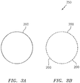
- the seal 200 may be manufactured as a continuous structure (see FIG. 3A ). In such cases the overall shape of the seal may be a circle, an ellipse, or may feature flat sides with full radius ends. In some embodiments, the seal 200 may be manufactured as a split-ring structure where the seal 200 may be configured to be incorporated as part of a hoop or ring. For example, referring to FIG. 3B multiple seals 200 may be used to form a larger sealing structure 350.
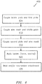
- the method 400 may be used to fabricate/manufacture a seal.
- the method 400 is described in the context of the seal 200, but it is understood that the method 400 may be adapted to accommodate other seals.
- a bristle pack (e.g., bristle pack 218) may be coupled to a first plate (e.g., plate 212).
- a first plate e.g., plate 212
- the bristle pack may be positioned adjacent to the first plate as shown in FIG. 2A .
- a wire mesh (e.g., wire mesh 252) may be coupled to the bristle pack.
- the wire mesh may be positioned adjacent to the bristle pack as shown in FIG. 2A .
- a second plate (e.g., plate 202) may be coupled to the wire mesh.
- the second plate may be positioned adjacent to the wire mesh as shown in FIG. 2A .
- a toolset (illustrated schematically via reference character 510 in FIG. 5 ) may be applied to the stack-up/coupling of layers obtained in blocks 404-416 as described above.
- the toolset 510 may be used to hold the layers 202, 252, 218, and 212 together or in a positional relationship/stack-up relative to one another, for example based on an application of force to the layers 202, 252, 218, and 212. Still further, the toolset 510 may cool one or more of the plate 202, the wire mesh 252, the bristle pack 218, or the plate 212. While the application of the toolset 510 is referred to in a separate block 422 in FIG. 4 , in accordance with aspects of the disclosure the toolset 510 may be applied as part of one or more of the blocks 404-416.
- a welding operation may occur along an end/surface 522 of the stack-up of the plate 202, 252, 218, and 212.
- the end/surface 522 may be substantially smooth/contiguous with respect to the stack-up of the layers 202, 252, 218, and 212.
- a welding operation may project through one or more of the layers 202, 252, 218, and 212 as denoted via arrow/reference character 534.
- the operation of block 428 may include electron beam (EB) welding or laser welding.
- the operation of block 428 may include attachment/securing of the wire mesh via mechanical techniques (e.g., crimping). While shown as a separate block, the operation of block 428 may be performed in conjunction with the application of the toolset in block 422 in some embodiments.
- FIG. 6 illustrates a flowchart of a method 600 that may be used to fabricate/manufacture a seal.
- the method 600 is described in the context of the seal 200, but it is understood that the method 600 may be adapted to accommodate other seals.
- a wire mesh (e.g., wire mesh 252) may be positioned adjacent to a first plate (e.g., plate 202).
- a bristle pack (e.g., bristle pack 218) may be positioned adjacent to the wire mesh.
- a second plate (e.g., plate 212) may be positioned adjacent to the bristle pack.
- a toolset (toolset 510 of FIG. 5 ) may be applied to hold the first plate, the wire mesh, the bristle pack, and the second plate in a stack-up.
- Application of the toolset 620 may provide similar features/functionality as described above in connection with block 422.
- an operation may be performed to form a brush seal.
- the operation of block 626 may include welding and/or mechanical attachment techniques similar to what is described above in connection with block 428.
- the blocks of the methods 400 and 600 are illustrative. In some embodiments the blocks/operations may occur in an order/sequence that is different from what is shown in FIG. 4 or FIG. 6 . In some embodiments, additional blocks/operations not shown may be included. At least some of the blocks/operations of the methods 400 and 600 may be combined in some embodiments.
- a seal that may be incorporated as part of one or more sections of an engine.
- a seal in accordance with this disclosure may include a windage cover that facilitates ease in the manufacture of the seal.
- aspects of the disclosure provide a light weight seal while increasing the reliability of the seal in terms of use/deployment by preserving the structural integrity of the seal (e.g., the bristle pack).
Landscapes
- Engineering & Computer Science (AREA)
- General Engineering & Computer Science (AREA)
- Mechanical Engineering (AREA)
- Turbine Rotor Nozzle Sealing (AREA)
- Sealing Devices (AREA)
Abstract
Description
- Seals are used in an aircraft engine to isolate a fluid from one or more areas/regions of the engine. For example, seals are used to control various characteristics (e.g., temperature, pressure) within areas/regions of the engine and ensure proper/efficient engine operation and stability. Brush seals are a type of seal that provides fluid isolation in the manner described above. A brush seal may be implemented as a bundle/package of bristles sandwiched between two plates.
- The bristles may need to be protected. For example, if the bristles are exposed to an excitation (e.g., windage) a bristle may have a tendency to become loose or even break-away from the bristle pack, in which case the bristle may impact (e.g., clog) a downstream component.
- Two types of covers are frequently used to protect the bristles of the brush seal. A first type of cover is a plate cover. Plate covers are bulky, add weight, and present difficulties in terms of the manufacturability of the brush seal. A second type of cover is a sheet metal cover. The sheet metal cover is thin and susceptible to degradation due to handling.
- The following presents a simplified summary in order to provide a basic understanding of some aspects of the disclosure. The summary is not an extensive overview of the disclosure. It is neither intended to identify key or critical elements of the disclosure nor to delineate the scope of the disclosure. The following summary merely presents some concepts of the disclosure in a simplified form as a prelude to the description below.
- Aspects of the disclosure are directed to a brush seal comprising a first plate, a wire mesh adjacent the first plate, a bristle pack adjacent the wire mesh, and a second plate adjacent the bristle pack. In some embodiments, the wire mesh is configured as a windage cover with respect to the bristle pack. In some embodiments, the wire mesh is configured to protect the bristle pack with respect to an airflow associated with an engine. In some embodiments, the airflow includes bleed air from a compressor section of the engine. In some embodiments, the wire mesh includes a metal alloy. In some embodiments, the wire mesh has a first length that is substantially equal to a second length of the bristle pack. In some embodiments, the wire mesh has a first length that is substantially less than a second length of the bristle pack. In some embodiments, the wire mesh has a first length that is greater than a second length of the second plate, and the first length is less than a third length of the bristle pack. In some embodiments, at least one of the bristle pack and the wire mesh includes a ceramic coat.
- Aspects of the disclosure are directed to a method comprising positioning a wire mesh adjacent to a first plate, positioning a bristle pack adjacent to the wire mesh, positioning a second plate adjacent to the bristle pack, applying a toolset to hold the first plate, the wire mesh, the bristle pack, and the second plate in a stack-up, and performing an operation to form a brush seal from the stack-up of the first plate, the wire mesh, the bristle pack, and the second plate. In some embodiments, the operation includes electron beam welding. In some embodiments, the operation includes a welding that projects through at least one of the first plate, the wire mesh, the bristle pack, and the second plate. In some embodiments, the operation includes a welding that is performed along an end of the stack-up. In some embodiments, the end is substantially contiguous in relation to the first plate, the wire mesh, the bristle pack, and the second plate. In some embodiments, the operation is performed in conjunction with the application of the toolset. In some embodiments, the operation includes laser welding. In some embodiments, the operation includes application of a mechanical attachment technique. In some embodiments, the mechanical attachment technique includes crimping
- The present disclosure is illustrated by way of example and not limited in the accompanying drawing figures in which like reference numerals indicate similar elements. The drawing figures are not necessarily drawn to scale unless specifically indicated otherwise.
-
FIG. 1 is a side cutaway illustration of a geared turbine engine. -
FIG. 2A illustrates a brush seal in accordance with aspects of this disclosure. -
FIG. 2B illustrates an arrangement of bristles within a bristle pack in accordance with aspects of this disclosure. -
FIG. 3A illustrates a seal arranged as a continuous structure in accordance with aspects of this disclosure. -
FIG. 3B illustrates a number of the seals arranged as a split-ring in forming a sealing structure in accordance with aspects of this disclosure. -
FIG. 4 illustrates a method for manufacturing a seal in accordance with aspects of this disclosure. -
FIG. 5 illustrates an application of a toolset to form a seal in accordance with aspects of this disclosure. -
FIG. 6 illustrates a method for manufacturing a seal in accordance with aspects of this disclosure. - It is noted that various connections are set forth between elements in the following description and in the drawings (the contents of which are included in this disclosure by way of reference). It is noted that these connections are general and, unless specified otherwise, may be direct or indirect and that this specification is not intended to be limiting in this respect. A coupling between two or more entities may refer to a direct connection or an indirect connection. An indirect connection may incorporate one or more intervening entities.
- In accordance with various aspects of the disclosure, apparatuses, systems and methods are described in connection with a seal configured for use on an engine. In some embodiments, a brush seal may include a wire mesh windage cover. The wire mesh windage cover may help to protect one or more bristles of a bristle pack.
- Aspects of the disclosure may be applied in connection with a gas turbine engine.
FIG. 1 is a side cutaway illustration of a gearedturbine engine 10. Thisturbine engine 10 extends along anaxial centerline 12 between anupstream airflow inlet 14 and adownstream airflow exhaust 16. Theturbine engine 10 includes afan section 18, acompressor section 19, acombustor section 20 and aturbine section 21. Thecompressor section 19 includes a low pressure compressor (LPC)section 19A and a high pressure compressor (HPC)section 19B. Theturbine section 21 includes a high pressure turbine (HPT)section 21 A and a low pressure turbine (LPT)section 21B. - The engine sections 18-21 are arranged sequentially along the
centerline 12 within anengine housing 22. Each of the engine sections 18-19B, 21A and 21B includes a respective rotor 24-28. Each of these rotors 24-28 includes a plurality of rotor blades arranged circumferentially around and connected to one or more respective rotor disks. The rotor blades, for example, may be formed integral with or mechanically fastened, welded, brazed, adhered and/or otherwise attached to the respective rotor disk(s). - The
fan rotor 24 is connected to agear train 30, for example, through afan shaft 32. Thegear train 30 and theLPC rotor 25 are connected to and driven by theLPT rotor 28 through alow speed shaft 33. TheHPC rotor 26 is connected to and driven by theHPT rotor 27 through ahigh speed shaft 34. The shafts 32-34 are rotatably supported by a plurality ofbearings 36; e.g., rolling element and/or thrust bearings. Each of thesebearings 36 is connected to theengine housing 22 by at least one stationary structure such as, for example, an annular support strut. - During operation, air enters the
turbine engine 10 through theairflow inlet 14, and is directed through thefan section 18 and into acore gas path 38 and abypass gas path 40. The air within thecore gas path 38 may be referred to as "core air". The air within thebypass gas path 40 may be referred to as "bypass air". The core air is directed through the engine sections 19-21, and exits theturbine engine 10 through theairflow exhaust 16 to provide forward engine thrust. Within thecombustor section 20, fuel is injected into acombustion chamber 42 and mixed with compressed core air. This fuel-core air mixture is ignited to power theturbine engine 10. The bypass air is directed through thebypass gas path 40 and out of theturbine engine 10 through abypass nozzle 44 to provide additional forward engine thrust. This additional forward engine thrust may account for a majority (e.g., more than 70 percent) of total engine thrust. Alternatively, at least some of the bypass air may be directed out of theturbine engine 10 through a thrust reverser to provide reverse engine thrust. -
FIG. 1 represents one possible configuration for a gearedgas turbine engine 10. Aspects of the disclosure may be applied in connection with other environments, including additional configurations for gas turbine engines. Aspects of the disclosure may be applied in connection with, e.g., turbojets, turboprops, low bypass ratio gas turbine engines, or high bypass ratio gas turbine engines. In some embodiments, a platform/configuration may utilize multiple flow streams and/or thrust augmentation. Any number of applications incorporating rotating machinery may incorporate aspects of this disclosure. Aspects of the disclosure may be applied in connection with static hardware. - Referring now to
FIG. 2A , abrush seal 200 is shown. Theseal 200 may be incorporated as part of one or more sections of the engine, such as for example thecompressor section 19 or theturbine section 21 of theengine 10 ofFIG. 1 . In some embodiments, theseal 200 may be used to interface a vane or a blade outer air seal (BOAS) of theengine 10. In some embodiments, theseal 200 may be used to interface rotating and static structure (e.g., as part of a pairing of a rotor and stator). - Referring back to
FIG. 2A , theseal 200 may include one or more plates, such as for example a top,first plate 202 and a bottom/backing,second plate 212. Theplates bristle pack 218. Thebristle pack 218 may include a plurality of wires/bristles. Theseal 200 may include awire mesh 252. Thewire mesh 252 may be configured as a windage cover with respect to the bristlepack 218 as described further below. - The
wire mesh 252 is shown as being disposed between thebristle pack 218 and theplate 202, adjacent to or along a surface of thebristle pack 218. Proceeding in a right-to-left manner inFIG. 2A , theseal 200 may include a stack-up of theplate 202, thewire mesh 252, thebristle pack 218, and theplate 212. - The
wire mesh 252 may be coupled to the bristlepack 218 during, e.g., a welding procedure/operation as described further below. Thewire mesh 252 may reduce/minimize, or even eliminate, an excitation of the bristles of thebristle pack 218 and provide additional sealing capability. For example, thewire mesh 252 may help to protect thebristle pack 218 against an excitation/flow associated with the reference character/arrow 264 shown inFIG. 2A . The excitation/flow 264 may be indicative of a compressor bleed air or any other secondary airflow (where, for example, a primary airflow may pertain to an airflow involved in combustion within theengine 10 ofFIG. 1 ). - The
plate 202, thewire mesh 252, thebristle pack 218, and theplate 212 may be made of one or more materials. For example, a metal alloy may be used in the fabrication/construction of one or more of theplate 202, thewire mesh 252, thebristle pack 218, and theplate 212. Theplate 202 or theplate 212 may include Inconel® 625 or Inconel® 718 alloy. Thewire mesh 252 may include Inconel® 625. - The
wire mesh 252 may have any thickness/width 252W that is suitable for the given application/environment at hand. In connection with use in an aircraft engine, thewidth 252W may have a value within a range of approximately 0.004 inches (approximately 0.10 millimeters) to approximately 0.060 inches (approximately 1.52 millimeters). - The
wire mesh 252 may have alength 252L. Thelength 252L may be substantially greater than, or even substantially equal to, alength 212L of theplate 212. Thelength 252L may be substantially less than, or even substantially equal to, alength 218L of thebristle pack 218. Having thelength 252L be less than thelength 218L may help to avoid thewire mesh 252 permanently bending in the presence of one or more forces. For example, if theseal 200 is deployed in connection with rotating machinery (e.g., an engine), deformations/imperfections/deflections in a rotor may result in forces that may cause a shaft to come into contract with thebristle pack 218. Providing a clearance/gap between thewire mesh 252 and the bristle pack 218 (illustratively in terms of the difference in theirrespective lengths wire mesh 252. - The
wire mesh 252 may have any number of candidate densities; the selection of a particular density may be based on the application/environment that theseal 200 is targeted to. A larger density (e.g., a tighter weave of the material used in the fabrication of the wire mesh 252) may make thewire mesh 252 stiffer and provide less flow area through thewire mesh 252. - To provide further environmental protection to the
seal 200, one or more portions of theseal 200 may include a coating. For example, thebristle pack 218 and/or thewire mesh 252 may include a ceramic coat, which may enable theseal 200 to operate in environments having elevated temperatures. - The
bristle pack 218 may include bristles having various types of orientations. For example, and referring toFIG. 2B , thebristle pack 218 is shown as including a first plurality/multiple ofbristles 218a and a second plurality/multiple ofbristles 218b that are oriented at an angle (denoted by reference character 274) relative to thebristles 218a. Theangle 274 may have a value within a range of 30 degrees and 60 degrees. Any number of orientations (e.g., angles) may be used in some embodiments. - The
seal 200 may be manufactured as a continuous structure (seeFIG. 3A ). In such cases the overall shape of the seal may be a circle, an ellipse, or may feature flat sides with full radius ends. In some embodiments, theseal 200 may be manufactured as a split-ring structure where theseal 200 may be configured to be incorporated as part of a hoop or ring. For example, referring toFIG. 3B multiple seals 200 may be used to form alarger sealing structure 350. - Referring to
FIG. 4 , a flowchart of amethod 400 is shown. Themethod 400 may be used to fabricate/manufacture a seal. Themethod 400 is described in the context of theseal 200, but it is understood that themethod 400 may be adapted to accommodate other seals. - In
block 404, a bristle pack (e.g., bristle pack 218) may be coupled to a first plate (e.g., plate 212). For example, as part ofblock 404 the bristle pack may be positioned adjacent to the first plate as shown inFIG. 2A . - In
block 410, a wire mesh (e.g., wire mesh 252) may be coupled to the bristle pack. For example, as part ofblock 410 the wire mesh may be positioned adjacent to the bristle pack as shown inFIG. 2A . - In
block 416, a second plate (e.g., plate 202) may be coupled to the wire mesh. For example, as part ofblock 416 the second plate may be positioned adjacent to the wire mesh as shown inFIG. 2A . - In
block 422, a toolset (illustrated schematically viareference character 510 inFIG. 5 ) may be applied to the stack-up/coupling of layers obtained in blocks 404-416 as described above. Thetoolset 510 may be used to hold thelayers layers toolset 510 may cool one or more of theplate 202, thewire mesh 252, thebristle pack 218, or theplate 212. While the application of thetoolset 510 is referred to in aseparate block 422 inFIG. 4 , in accordance with aspects of the disclosure thetoolset 510 may be applied as part of one or more of the blocks 404-416. - In
block 428, a welding operation may occur along an end/surface 522 of the stack-up of theplate surface 522 may be substantially smooth/contiguous with respect to the stack-up of thelayers layers reference character 534. The operation ofblock 428 may include electron beam (EB) welding or laser welding. Moreover, the operation ofblock 428 may include attachment/securing of the wire mesh via mechanical techniques (e.g., crimping). While shown as a separate block, the operation ofblock 428 may be performed in conjunction with the application of the toolset inblock 422 in some embodiments. -
FIG. 6 illustrates a flowchart of amethod 600 that may be used to fabricate/manufacture a seal. Themethod 600 is described in the context of theseal 200, but it is understood that themethod 600 may be adapted to accommodate other seals. - In
block 602, a wire mesh (e.g., wire mesh 252) may be positioned adjacent to a first plate (e.g., plate 202). - In
block 608, a bristle pack (e.g., bristle pack 218) may be positioned adjacent to the wire mesh. - In
block 614, a second plate (e.g., plate 212) may be positioned adjacent to the bristle pack. - In
block 620, a toolset (toolset 510 ofFIG. 5 ) may be applied to hold the first plate, the wire mesh, the bristle pack, and the second plate in a stack-up. Application of thetoolset 620 may provide similar features/functionality as described above in connection withblock 422. - In
block 626, an operation may be performed to form a brush seal. The operation ofblock 626 may include welding and/or mechanical attachment techniques similar to what is described above in connection withblock 428. - The blocks of the
methods FIG. 4 orFIG. 6 . In some embodiments, additional blocks/operations not shown may be included. At least some of the blocks/operations of themethods - Technical effects and benefits of this disclosure include a seal that may be incorporated as part of one or more sections of an engine. Relative to a conventional seal, a seal in accordance with this disclosure may include a windage cover that facilitates ease in the manufacture of the seal. Furthermore, aspects of the disclosure provide a light weight seal while increasing the reliability of the seal in terms of use/deployment by preserving the structural integrity of the seal (e.g., the bristle pack).
- Aspects of the disclosure have been described in terms of illustrative embodiments thereof. Numerous other embodiments, modifications, and variations within the scope and spirit of the appended claims will occur to persons of ordinary skill in the art from a review of this disclosure. For example, one of ordinary skill in the art will appreciate that the steps described in conjunction with the illustrative figures may be performed in other than the recited order, and that one or more steps illustrated may be optional in accordance with aspects of the disclosure. One or more features described in connection with a first embodiment may be combined with one or more features of one or more additional embodiments.
Claims (15)
- A brush seal (200) comprising:a first plate (202);a wire mesh (252) adjacent the first plate (202);a bristle pack (218) adjacent the wire mesh (252); anda second plate (212) adjacent the bristle pack (218).
- The brush seal (200) of claim 1, wherein the wire mesh (252) is configured as a windage cover with respect to the bristle pack (218).
- The brush seal (200) of claim 2, wherein the wire mesh (252) is configured to protect the bristle pack (218) with respect to an airflow (264) associated with an engine (10), optionally wherein the airflow (264) includes bleed air from a compressor section (19) of the engine (10).
- The brush seal (200) of claim 1, 2 or 3, wherein the wire mesh (252) includes a metal alloy.
- The brush seal (200) of any preceding claim, wherein the wire mesh (252) has a first length (252L) that is substantially equal to a second length (218L) of the bristle pack (218).
- The brush seal (200) of any of claims 1 to 4, wherein the wire mesh (252) has a first length (252L) that is substantially less than a second length (218L) of the bristle pack (218).
- The brush seal (200) of any of claims 1 to 4, wherein the wire mesh (252) has a first length (252L) that is greater than a second length (212L) of the second plate (212), and wherein the first length (252L) is less than a third length (218L) of the bristle pack (218).
- The brush seal (200) of any preceding claim, wherein at least one of the bristle pack (218) and the wire mesh (252) includes a ceramic coat.
- A method comprising:positioning a wire mesh (252) adjacent to a first plate (202);positioning a bristle pack (218) adjacent to the wire mesh (252);positioning a second plate (212) adjacent to the bristle pack (218);applying a toolset (510) to hold the first plate (202), the wire mesh (252), the bristle pack (218), and the second plate (212) in a stack-up; andperforming an operation to form a brush seal (200) from the stack-up of the first plate (202), the wire mesh (252), the bristle pack (218), and the second plate (212).
- The method of claim 9, wherein the operation includes electron beam welding or laser welding.
- The method of claim 9 or 10, wherein the operation includes a welding that projects through at least one of the first plate (202), the wire mesh (252), the bristle pack (218), and the second plate (212).
- The method of claim 9, 10 or 11, wherein the operation includes a welding that is performed along an end (522) of the stack-up.
- The method of claim 12, wherein the end (522) is substantially contiguous in relation to the first plate (202), the wire mesh (252), the bristle pack (218), and the second plate (212).
- The method of any of claims 9 to 13, wherein the operation is performed in conjunction with the application of the toolset (510).
- The method of any of claims 9 to 14, wherein the operation includes application of a mechanical attachment technique, optionally wherein the mechanical attachment technique includes crimping.
Applications Claiming Priority (1)
| Application Number | Priority Date | Filing Date | Title |
|---|---|---|---|
| US15/092,793 US10563771B2 (en) | 2016-04-07 | 2016-04-07 | Wire mesh brush seal windage cover |
Publications (2)
| Publication Number | Publication Date |
|---|---|
| EP3228906A1 true EP3228906A1 (en) | 2017-10-11 |
| EP3228906B1 EP3228906B1 (en) | 2020-10-28 |
Family
ID=58548986
Family Applications (1)
| Application Number | Title | Priority Date | Filing Date |
|---|---|---|---|
| EP17165310.8A Active EP3228906B1 (en) | 2016-04-07 | 2017-04-06 | Wire mesh brush seal windage cover |
Country Status (2)
| Country | Link |
|---|---|
| US (2) | US10563771B2 (en) |
| EP (1) | EP3228906B1 (en) |
Families Citing this family (1)
| Publication number | Priority date | Publication date | Assignee | Title |
|---|---|---|---|---|
| US11384841B2 (en) * | 2019-12-06 | 2022-07-12 | Raytheon Technologies Corporation | Brush seal with crossing bristles |
Citations (4)
| Publication number | Priority date | Publication date | Assignee | Title |
|---|---|---|---|---|
| DE19527605A1 (en) * | 1995-07-28 | 1997-02-27 | Mtu Muenchen Gmbh | Brush seal for turbo engines esp gas turbine engines |
| GB2355049A (en) * | 1999-10-05 | 2001-04-11 | Rolls Royce Plc | Differential lay brush seal |
| US20120326392A1 (en) * | 2011-06-27 | 2012-12-27 | General Electric Company | Brush seal |
| EP2559923A1 (en) * | 2011-08-17 | 2013-02-20 | General Electric Company | A self-lubricating brush seal assembly and method of reducing leakage |
Family Cites Families (49)
| Publication number | Priority date | Publication date | Assignee | Title |
|---|---|---|---|---|
| US3020185A (en) | 1958-07-28 | 1962-02-06 | Connecticut Hard Rubber Co | Wire reinforced polytetrafluoroethylene seal |
| US3033722A (en) | 1959-12-01 | 1962-05-08 | Metal Textile Corp | Compressible metal gasket and method of making same |
| USRE30206E (en) * | 1973-11-23 | 1980-02-05 | Rolls Royce (1971) Limited | Seals and method of manufacture thereof |
| US4093245A (en) | 1977-06-02 | 1978-06-06 | Mosser Industries, Inc. | Mechanical sealing means |
| GB8504331D0 (en) | 1985-02-20 | 1985-03-20 | Rolls Royce | Brush seals |
| GB8712681D0 (en) | 1987-05-29 | 1987-07-01 | Cross Mfg Co 1938 Ltd | Brush seals |
| US5114159A (en) | 1991-08-05 | 1992-05-19 | United Technologies Corporation | Brush seal and damper |
| US5181728A (en) | 1991-09-23 | 1993-01-26 | General Electric Company | Trenched brush seal |
| US5201530A (en) | 1991-10-18 | 1993-04-13 | United Technologies Corporation | Multi-layered brush seal |
| US5265412A (en) | 1992-07-28 | 1993-11-30 | General Electric Company | Self-accommodating brush seal for gas turbine combustor |
| US5568931A (en) * | 1992-08-20 | 1996-10-29 | General Electric Company | Brush seal |
| US6357672B1 (en) | 1995-07-06 | 2002-03-19 | United Technologies Corporation | Sealing means for a multi-axis nozzle |
| IT1284468B1 (en) * | 1995-07-28 | 1998-05-21 | Mtu Muenchen Gmbh | BRUSH GASKET FOR TURBOMACHINES |
| DE19529655C2 (en) * | 1995-08-11 | 1999-04-22 | Mtu Muenchen Gmbh | Brush seal for turbomachinery |
| DE29600193U1 (en) | 1996-01-08 | 1996-03-14 | MTU Motoren- und Turbinen-Union München GmbH, 80995 München | Brush seal with C-shaped clamping ring |
| DE19645163C2 (en) | 1996-11-02 | 2000-10-05 | Mtu Muenchen Gmbh | Brush seal for rotor-stator arrangement |
| DE19720648C2 (en) | 1997-05-16 | 2000-07-13 | Mtu Muenchen Gmbh | Brush seal with front and support plate |
| US6250640B1 (en) | 1998-08-17 | 2001-06-26 | General Electric Co. | Brush seals for steam turbine applications |
| US6170831B1 (en) | 1998-12-23 | 2001-01-09 | United Technologies Corporation | Axial brush seal for gas turbine engines |
| US6406027B1 (en) | 1999-07-22 | 2002-06-18 | General Electric Company | Brush seal and machine having a brush seal |
| DE19962316C2 (en) | 1999-12-23 | 2002-07-18 | Mtu Aero Engines Gmbh | brush seal |
| US6913265B2 (en) * | 2000-08-09 | 2005-07-05 | Advanced Components & Materials, Inc. | Brush seal assembly, method of manufacture and use |
| US6488471B1 (en) | 2000-10-04 | 2002-12-03 | The United States Of America As Represented By The Secretary Of The Air Force | Gas-turbine brush seals with permanent radial gap |
| US6431827B1 (en) | 2000-12-21 | 2002-08-13 | General Electric Company | Bucket tip brush seals in steam turbines and methods of installation |
| JP4689882B2 (en) | 2001-06-29 | 2011-05-25 | イーグル工業株式会社 | Plate brush seal device |
| US20040173969A1 (en) * | 2001-10-25 | 2004-09-09 | Smith Walter J. | Turbine brush seal |
| US20030160392A1 (en) * | 2002-02-12 | 2003-08-28 | Szymbor John A. | Bristle arrangement for brush seal, method and assembly for making same, and method of making brush seal |
| US6996885B2 (en) | 2002-03-20 | 2006-02-14 | United Technologies Corporation | Method of making bristle arrangement for brush seal |
| US7275215B2 (en) * | 2002-07-29 | 2007-09-25 | Cerulean Studios, Llc | System and method for managing contacts in an instant messaging environment |
| US7052015B2 (en) * | 2002-08-06 | 2006-05-30 | United Technologies Corporation | Cooling arrangement for brush seal |
| WO2004046900A2 (en) * | 2002-11-21 | 2004-06-03 | Sony Ericsson Mobile Communications Ab | Flexible conductors connected between two parts of a portable electronic device |
| US7270333B2 (en) | 2002-11-27 | 2007-09-18 | United Technologies Corporation | Brush seal with adjustable clearance |
| US20050006851A1 (en) | 2003-07-09 | 2005-01-13 | Addis Mark E. | Brush seal with windage control |
| US7595451B2 (en) | 2003-07-10 | 2009-09-29 | Acs Industries, Inc. | Wire mesh seal element with soft, flat, hard, and round wires |
| DE10337867B4 (en) | 2003-08-18 | 2020-04-23 | MTU Aero Engines AG | Brush seal |
| US20080284107A1 (en) | 2004-05-04 | 2008-11-20 | Flaherty Andrew L | Ceramic Brush Seals |
| US7653993B2 (en) | 2005-09-29 | 2010-02-02 | General Electric Company | Method of manufacturing a brush seal for sealing between stationary and rotary components |
| US20080003099A1 (en) | 2006-06-30 | 2008-01-03 | Honeywell International, Inc. | Closed bias air film riding seal in event of housing breach for shared engine lubrication accessory gearboxes |
| EP2079910B1 (en) * | 2006-10-17 | 2015-01-07 | BorgWarner, Inc. | Ring seals for gas sealing and vibration damping |
| US20080136112A1 (en) * | 2006-12-08 | 2008-06-12 | United Technologies Corporation | Brush seal assemblies utilizing a threaded fastening method |
| US8727354B2 (en) | 2008-01-15 | 2014-05-20 | United Technologies Corporation | Brush seal assembly and method of manufacturing same |
| DE102008060371A1 (en) | 2008-12-03 | 2010-06-10 | Mtu Aero Engines Gmbh | brush seal |
| FR2967748B1 (en) | 2010-11-24 | 2013-09-20 | Snecma | BRUSH ANNULAR JOINT SEALING SYSTEM |
| US8777563B2 (en) | 2011-01-31 | 2014-07-15 | General Electric Company | Axial brush seal |
| US20120326393A1 (en) | 2011-06-27 | 2012-12-27 | General Electric Company | Brush seal |
| WO2014014426A2 (en) | 2012-06-28 | 2014-01-23 | Sdm Siradişi Arge Ve Mühendi̇sli̇k Sanayi̇ Ti̇caret Li̇mi̇ted Şi̇rketi̇ | Brush seal for high pressure applications |
| FR2998611B1 (en) | 2012-11-29 | 2018-08-10 | Safran Aircraft Engines | SEAL JOINT ASSEMBLY FOR A TURBOMACHINE COMPRISING A BRUSH JOINT |
| US10208674B2 (en) | 2013-03-13 | 2019-02-19 | United Technologies Corporation | Multi-axial brush seal |
| WO2015147967A1 (en) | 2014-03-27 | 2015-10-01 | United Technologies Corporation | Gas turbine engine and seal assembly therefore |
-
2016
- 2016-04-07 US US15/092,793 patent/US10563771B2/en active Active
-
2017
- 2017-04-06 EP EP17165310.8A patent/EP3228906B1/en active Active
-
2019
- 2019-10-10 US US16/598,168 patent/US11300209B2/en active Active
Patent Citations (4)
| Publication number | Priority date | Publication date | Assignee | Title |
|---|---|---|---|---|
| DE19527605A1 (en) * | 1995-07-28 | 1997-02-27 | Mtu Muenchen Gmbh | Brush seal for turbo engines esp gas turbine engines |
| GB2355049A (en) * | 1999-10-05 | 2001-04-11 | Rolls Royce Plc | Differential lay brush seal |
| US20120326392A1 (en) * | 2011-06-27 | 2012-12-27 | General Electric Company | Brush seal |
| EP2559923A1 (en) * | 2011-08-17 | 2013-02-20 | General Electric Company | A self-lubricating brush seal assembly and method of reducing leakage |
Also Published As
| Publication number | Publication date |
|---|---|
| US10563771B2 (en) | 2020-02-18 |
| US20170292609A1 (en) | 2017-10-12 |
| EP3228906B1 (en) | 2020-10-28 |
| US11300209B2 (en) | 2022-04-12 |
| US20200049256A1 (en) | 2020-02-13 |
Similar Documents
| Publication | Publication Date | Title |
|---|---|---|
| US10935139B2 (en) | Dual-ended brush seal assembly and method of manufacture | |
| US10487678B2 (en) | Engine air sealing by seals in series | |
| US10428953B2 (en) | C-seal backed brush seal with a compressible core | |
| US10718270B2 (en) | Hydrostatic non-contact seal with dual material | |
| US9850773B2 (en) | Dual walled seal assembly | |
| US10641180B2 (en) | Hydrostatic non-contact seal with varied thickness beams | |
| US10337621B2 (en) | Hydrostatic non-contact seal with weight reduction pocket | |
| US11028712B2 (en) | Seal support feature for brush seals | |
| US20160040600A1 (en) | Multi-axial brush seal | |
| EP2914814A1 (en) | Belly band seal with underlapping ends | |
| US20180283193A1 (en) | Sealing part for a gas turbine and method for manufacturing such a sealing part | |
| US10830048B2 (en) | Gas turbine rotor disk having scallop shield feature | |
| US10273821B2 (en) | Advanced stationary sealing cooled cross-section for axial retention of ceramic matrix composite shrouds | |
| US11300209B2 (en) | Wire mesh brush seal windage cover | |
| US11268402B2 (en) | Blade outer air seal cooling fin | |
| EP3244021B1 (en) | Engine comprising a seal |
Legal Events
| Date | Code | Title | Description |
|---|---|---|---|
| PUAI | Public reference made under article 153(3) epc to a published international application that has entered the european phase |
Free format text: ORIGINAL CODE: 0009012 |
|
| STAA | Information on the status of an ep patent application or granted ep patent |
Free format text: STATUS: THE APPLICATION HAS BEEN PUBLISHED |
|
| AK | Designated contracting states |
Kind code of ref document: A1 Designated state(s): AL AT BE BG CH CY CZ DE DK EE ES FI FR GB GR HR HU IE IS IT LI LT LU LV MC MK MT NL NO PL PT RO RS SE SI SK SM TR |
|
| AX | Request for extension of the european patent |
Extension state: BA ME |
|
| STAA | Information on the status of an ep patent application or granted ep patent |
Free format text: STATUS: REQUEST FOR EXAMINATION WAS MADE |
|
| 17P | Request for examination filed |
Effective date: 20180411 |
|
| RBV | Designated contracting states (corrected) |
Designated state(s): AL AT BE BG CH CY CZ DE DK EE ES FI FR GB GR HR HU IE IS IT LI LT LU LV MC MK MT NL NO PL PT RO RS SE SI SK SM TR |
|
| STAA | Information on the status of an ep patent application or granted ep patent |
Free format text: STATUS: EXAMINATION IS IN PROGRESS |
|
| 17Q | First examination report despatched |
Effective date: 20180911 |
|
| RIC1 | Information provided on ipc code assigned before grant |
Ipc: F16J 15/3288 20160101AFI20200319BHEP Ipc: F04D 29/08 20060101ALI20200319BHEP |
|
| GRAP | Despatch of communication of intention to grant a patent |
Free format text: ORIGINAL CODE: EPIDOSNIGR1 |
|
| STAA | Information on the status of an ep patent application or granted ep patent |
Free format text: STATUS: GRANT OF PATENT IS INTENDED |
|
| INTG | Intention to grant announced |
Effective date: 20200506 |
|
| GRAS | Grant fee paid |
Free format text: ORIGINAL CODE: EPIDOSNIGR3 |
|
| GRAA | (expected) grant |
Free format text: ORIGINAL CODE: 0009210 |
|
| STAA | Information on the status of an ep patent application or granted ep patent |
Free format text: STATUS: THE PATENT HAS BEEN GRANTED |
|
| AK | Designated contracting states |
Kind code of ref document: B1 Designated state(s): AL AT BE BG CH CY CZ DE DK EE ES FI FR GB GR HR HU IE IS IT LI LT LU LV MC MK MT NL NO PL PT RO RS SE SI SK SM TR |
|
| REG | Reference to a national code |
Ref country code: GB Ref legal event code: FG4D |
|
| REG | Reference to a national code |
Ref country code: CH Ref legal event code: EP |
|
| REG | Reference to a national code |
Ref country code: AT Ref legal event code: REF Ref document number: 1328567 Country of ref document: AT Kind code of ref document: T Effective date: 20201115 |
|
| REG | Reference to a national code |
Ref country code: DE Ref legal event code: R096 Ref document number: 602017026172 Country of ref document: DE |
|
| REG | Reference to a national code |
Ref country code: IE Ref legal event code: FG4D |
|
| REG | Reference to a national code |
Ref country code: AT Ref legal event code: MK05 Ref document number: 1328567 Country of ref document: AT Kind code of ref document: T Effective date: 20201028 |
|
| RAP2 | Party data changed (patent owner data changed or rights of a patent transferred) |
Owner name: RAYTHEON TECHNOLOGIES CORPORATION |
|
| REG | Reference to a national code |
Ref country code: NL Ref legal event code: MP Effective date: 20201028 |
|
| PG25 | Lapsed in a contracting state [announced via postgrant information from national office to epo] |
Ref country code: GR Free format text: LAPSE BECAUSE OF FAILURE TO SUBMIT A TRANSLATION OF THE DESCRIPTION OR TO PAY THE FEE WITHIN THE PRESCRIBED TIME-LIMIT Effective date: 20210129 Ref country code: FI Free format text: LAPSE BECAUSE OF FAILURE TO SUBMIT A TRANSLATION OF THE DESCRIPTION OR TO PAY THE FEE WITHIN THE PRESCRIBED TIME-LIMIT Effective date: 20201028 Ref country code: NO Free format text: LAPSE BECAUSE OF FAILURE TO SUBMIT A TRANSLATION OF THE DESCRIPTION OR TO PAY THE FEE WITHIN THE PRESCRIBED TIME-LIMIT Effective date: 20210128 Ref country code: NL Free format text: LAPSE BECAUSE OF FAILURE TO SUBMIT A TRANSLATION OF THE DESCRIPTION OR TO PAY THE FEE WITHIN THE PRESCRIBED TIME-LIMIT Effective date: 20201028 Ref country code: RS Free format text: LAPSE BECAUSE OF FAILURE TO SUBMIT A TRANSLATION OF THE DESCRIPTION OR TO PAY THE FEE WITHIN THE PRESCRIBED TIME-LIMIT Effective date: 20201028 Ref country code: PT Free format text: LAPSE BECAUSE OF FAILURE TO SUBMIT A TRANSLATION OF THE DESCRIPTION OR TO PAY THE FEE WITHIN THE PRESCRIBED TIME-LIMIT Effective date: 20210301 |
|
| REG | Reference to a national code |
Ref country code: LT Ref legal event code: MG4D |
|
| PG25 | Lapsed in a contracting state [announced via postgrant information from national office to epo] |
Ref country code: SE Free format text: LAPSE BECAUSE OF FAILURE TO SUBMIT A TRANSLATION OF THE DESCRIPTION OR TO PAY THE FEE WITHIN THE PRESCRIBED TIME-LIMIT Effective date: 20201028 Ref country code: AT Free format text: LAPSE BECAUSE OF FAILURE TO SUBMIT A TRANSLATION OF THE DESCRIPTION OR TO PAY THE FEE WITHIN THE PRESCRIBED TIME-LIMIT Effective date: 20201028 Ref country code: ES Free format text: LAPSE BECAUSE OF FAILURE TO SUBMIT A TRANSLATION OF THE DESCRIPTION OR TO PAY THE FEE WITHIN THE PRESCRIBED TIME-LIMIT Effective date: 20201028 Ref country code: IS Free format text: LAPSE BECAUSE OF FAILURE TO SUBMIT A TRANSLATION OF THE DESCRIPTION OR TO PAY THE FEE WITHIN THE PRESCRIBED TIME-LIMIT Effective date: 20210228 Ref country code: PL Free format text: LAPSE BECAUSE OF FAILURE TO SUBMIT A TRANSLATION OF THE DESCRIPTION OR TO PAY THE FEE WITHIN THE PRESCRIBED TIME-LIMIT Effective date: 20201028 Ref country code: LV Free format text: LAPSE BECAUSE OF FAILURE TO SUBMIT A TRANSLATION OF THE DESCRIPTION OR TO PAY THE FEE WITHIN THE PRESCRIBED TIME-LIMIT Effective date: 20201028 Ref country code: BG Free format text: LAPSE BECAUSE OF FAILURE TO SUBMIT A TRANSLATION OF THE DESCRIPTION OR TO PAY THE FEE WITHIN THE PRESCRIBED TIME-LIMIT Effective date: 20210128 |
|
| PG25 | Lapsed in a contracting state [announced via postgrant information from national office to epo] |
Ref country code: HR Free format text: LAPSE BECAUSE OF FAILURE TO SUBMIT A TRANSLATION OF THE DESCRIPTION OR TO PAY THE FEE WITHIN THE PRESCRIBED TIME-LIMIT Effective date: 20201028 |
|
| REG | Reference to a national code |
Ref country code: DE Ref legal event code: R097 Ref document number: 602017026172 Country of ref document: DE |
|
| PG25 | Lapsed in a contracting state [announced via postgrant information from national office to epo] |
Ref country code: CZ Free format text: LAPSE BECAUSE OF FAILURE TO SUBMIT A TRANSLATION OF THE DESCRIPTION OR TO PAY THE FEE WITHIN THE PRESCRIBED TIME-LIMIT Effective date: 20201028 Ref country code: EE Free format text: LAPSE BECAUSE OF FAILURE TO SUBMIT A TRANSLATION OF THE DESCRIPTION OR TO PAY THE FEE WITHIN THE PRESCRIBED TIME-LIMIT Effective date: 20201028 Ref country code: LT Free format text: LAPSE BECAUSE OF FAILURE TO SUBMIT A TRANSLATION OF THE DESCRIPTION OR TO PAY THE FEE WITHIN THE PRESCRIBED TIME-LIMIT Effective date: 20201028 Ref country code: SM Free format text: LAPSE BECAUSE OF FAILURE TO SUBMIT A TRANSLATION OF THE DESCRIPTION OR TO PAY THE FEE WITHIN THE PRESCRIBED TIME-LIMIT Effective date: 20201028 Ref country code: RO Free format text: LAPSE BECAUSE OF FAILURE TO SUBMIT A TRANSLATION OF THE DESCRIPTION OR TO PAY THE FEE WITHIN THE PRESCRIBED TIME-LIMIT Effective date: 20201028 Ref country code: SK Free format text: LAPSE BECAUSE OF FAILURE TO SUBMIT A TRANSLATION OF THE DESCRIPTION OR TO PAY THE FEE WITHIN THE PRESCRIBED TIME-LIMIT Effective date: 20201028 |
|
| PG25 | Lapsed in a contracting state [announced via postgrant information from national office to epo] |
Ref country code: DK Free format text: LAPSE BECAUSE OF FAILURE TO SUBMIT A TRANSLATION OF THE DESCRIPTION OR TO PAY THE FEE WITHIN THE PRESCRIBED TIME-LIMIT Effective date: 20201028 |
|
| PLBE | No opposition filed within time limit |
Free format text: ORIGINAL CODE: 0009261 |
|
| STAA | Information on the status of an ep patent application or granted ep patent |
Free format text: STATUS: NO OPPOSITION FILED WITHIN TIME LIMIT |
|
| 26N | No opposition filed |
Effective date: 20210729 |
|
| PG25 | Lapsed in a contracting state [announced via postgrant information from national office to epo] |
Ref country code: IT Free format text: LAPSE BECAUSE OF FAILURE TO SUBMIT A TRANSLATION OF THE DESCRIPTION OR TO PAY THE FEE WITHIN THE PRESCRIBED TIME-LIMIT Effective date: 20201028 Ref country code: AL Free format text: LAPSE BECAUSE OF FAILURE TO SUBMIT A TRANSLATION OF THE DESCRIPTION OR TO PAY THE FEE WITHIN THE PRESCRIBED TIME-LIMIT Effective date: 20201028 |
|
| PG25 | Lapsed in a contracting state [announced via postgrant information from national office to epo] |
Ref country code: MC Free format text: LAPSE BECAUSE OF FAILURE TO SUBMIT A TRANSLATION OF THE DESCRIPTION OR TO PAY THE FEE WITHIN THE PRESCRIBED TIME-LIMIT Effective date: 20201028 Ref country code: SI Free format text: LAPSE BECAUSE OF FAILURE TO SUBMIT A TRANSLATION OF THE DESCRIPTION OR TO PAY THE FEE WITHIN THE PRESCRIBED TIME-LIMIT Effective date: 20201028 |
|
| PG25 | Lapsed in a contracting state [announced via postgrant information from national office to epo] |
Ref country code: LU Free format text: LAPSE BECAUSE OF NON-PAYMENT OF DUE FEES Effective date: 20210406 |
|
| REG | Reference to a national code |
Ref country code: BE Ref legal event code: MM Effective date: 20210430 |
|
| PG25 | Lapsed in a contracting state [announced via postgrant information from national office to epo] |
Ref country code: LI Free format text: LAPSE BECAUSE OF NON-PAYMENT OF DUE FEES Effective date: 20210430 Ref country code: CH Free format text: LAPSE BECAUSE OF NON-PAYMENT OF DUE FEES Effective date: 20210430 |
|
| PG25 | Lapsed in a contracting state [announced via postgrant information from national office to epo] |
Ref country code: IE Free format text: LAPSE BECAUSE OF NON-PAYMENT OF DUE FEES Effective date: 20210406 |
|
| PG25 | Lapsed in a contracting state [announced via postgrant information from national office to epo] |
Ref country code: IS Free format text: LAPSE BECAUSE OF FAILURE TO SUBMIT A TRANSLATION OF THE DESCRIPTION OR TO PAY THE FEE WITHIN THE PRESCRIBED TIME-LIMIT Effective date: 20210228 |
|
| PG25 | Lapsed in a contracting state [announced via postgrant information from national office to epo] |
Ref country code: BE Free format text: LAPSE BECAUSE OF NON-PAYMENT OF DUE FEES Effective date: 20210430 |
|
| PG25 | Lapsed in a contracting state [announced via postgrant information from national office to epo] |
Ref country code: HU Free format text: LAPSE BECAUSE OF FAILURE TO SUBMIT A TRANSLATION OF THE DESCRIPTION OR TO PAY THE FEE WITHIN THE PRESCRIBED TIME-LIMIT; INVALID AB INITIO Effective date: 20170406 |
|
| P01 | Opt-out of the competence of the unified patent court (upc) registered |
Effective date: 20230520 |
|
| PG25 | Lapsed in a contracting state [announced via postgrant information from national office to epo] |
Ref country code: CY Free format text: LAPSE BECAUSE OF FAILURE TO SUBMIT A TRANSLATION OF THE DESCRIPTION OR TO PAY THE FEE WITHIN THE PRESCRIBED TIME-LIMIT Effective date: 20201028 |
|
| PG25 | Lapsed in a contracting state [announced via postgrant information from national office to epo] |
Ref country code: MK Free format text: LAPSE BECAUSE OF FAILURE TO SUBMIT A TRANSLATION OF THE DESCRIPTION OR TO PAY THE FEE WITHIN THE PRESCRIBED TIME-LIMIT Effective date: 20201028 |
|
| PG25 | Lapsed in a contracting state [announced via postgrant information from national office to epo] |
Ref country code: MT Free format text: LAPSE BECAUSE OF FAILURE TO SUBMIT A TRANSLATION OF THE DESCRIPTION OR TO PAY THE FEE WITHIN THE PRESCRIBED TIME-LIMIT Effective date: 20201028 |
|
| PGFP | Annual fee paid to national office [announced via postgrant information from national office to epo] |
Ref country code: DE Payment date: 20250319 Year of fee payment: 9 |
|
| REG | Reference to a national code |
Ref country code: DE Ref legal event code: R081 Ref document number: 602017026172 Country of ref document: DE Owner name: RTX CORPORATION (N.D.GES.D. STAATES DELAWARE),, US Free format text: FORMER OWNER: UNITED TECHNOLOGIES CORPORATION, FARMINGTON, CONN., US |
|
| PG25 | Lapsed in a contracting state [announced via postgrant information from national office to epo] |
Ref country code: TR Free format text: LAPSE BECAUSE OF FAILURE TO SUBMIT A TRANSLATION OF THE DESCRIPTION OR TO PAY THE FEE WITHIN THE PRESCRIBED TIME-LIMIT Effective date: 20201028 |
|
| PGFP | Annual fee paid to national office [announced via postgrant information from national office to epo] |
Ref country code: GB Payment date: 20260319 Year of fee payment: 10 |
|
| PGFP | Annual fee paid to national office [announced via postgrant information from national office to epo] |
Ref country code: FR Payment date: 20260319 Year of fee payment: 10 |