EP3228900A1 - Novel damping structure and construction method thereof - Google Patents
Novel damping structure and construction method thereof Download PDFInfo
- Publication number
- EP3228900A1 EP3228900A1 EP15842222.0A EP15842222A EP3228900A1 EP 3228900 A1 EP3228900 A1 EP 3228900A1 EP 15842222 A EP15842222 A EP 15842222A EP 3228900 A1 EP3228900 A1 EP 3228900A1
- Authority
- EP
- European Patent Office
- Prior art keywords
- friction plate
- shaft sleeve
- metal frame
- extending
- damping structure
- Prior art date
- Legal status (The legal status is an assumption and is not a legal conclusion. Google has not performed a legal analysis and makes no representation as to the accuracy of the status listed.)
- Withdrawn
Links
- 238000013016 damping Methods 0.000 title claims abstract description 43
- 238000010276 construction Methods 0.000 title 1
- 229910052751 metal Inorganic materials 0.000 claims abstract description 47
- 239000002184 metal Substances 0.000 claims abstract description 47
- 238000001125 extrusion Methods 0.000 claims abstract description 19
- 238000000034 method Methods 0.000 claims abstract description 17
- 230000008569 process Effects 0.000 claims abstract description 15
- 229910000838 Al alloy Inorganic materials 0.000 claims abstract description 13
- 229910000881 Cu alloy Inorganic materials 0.000 claims abstract description 9
- 238000004519 manufacturing process Methods 0.000 claims abstract description 8
- 238000003825 pressing Methods 0.000 claims abstract description 8
- 208000016113 North Carolina macular dystrophy Diseases 0.000 claims abstract description 7
- VYZAMTAEIAYCRO-UHFFFAOYSA-N Chromium Chemical compound [Cr] VYZAMTAEIAYCRO-UHFFFAOYSA-N 0.000 claims description 5
- 239000000463 material Substances 0.000 claims description 5
- 238000007747 plating Methods 0.000 claims description 5
- 239000010935 stainless steel Substances 0.000 claims description 5
- 229910001220 stainless steel Inorganic materials 0.000 claims description 5
- 229920006324 polyoxymethylene Polymers 0.000 claims description 3
- 239000004033 plastic Substances 0.000 abstract description 16
- 229920003023 plastic Polymers 0.000 abstract description 16
- 238000005452 bending Methods 0.000 description 4
- 238000003860 storage Methods 0.000 description 4
- 238000005266 casting Methods 0.000 description 3
- 230000000694 effects Effects 0.000 description 3
- 229910052782 aluminium Inorganic materials 0.000 description 2
- XAGFODPZIPBFFR-UHFFFAOYSA-N aluminium Chemical compound [Al] XAGFODPZIPBFFR-UHFFFAOYSA-N 0.000 description 2
- 238000003780 insertion Methods 0.000 description 2
- 230000037431 insertion Effects 0.000 description 2
- PWHULOQIROXLJO-UHFFFAOYSA-N Manganese Chemical compound [Mn] PWHULOQIROXLJO-UHFFFAOYSA-N 0.000 description 1
- 229910000639 Spring steel Inorganic materials 0.000 description 1
- 229910000831 Steel Inorganic materials 0.000 description 1
- 230000002159 abnormal effect Effects 0.000 description 1
- 238000005299 abrasion Methods 0.000 description 1
- 230000009471 action Effects 0.000 description 1
- 230000006835 compression Effects 0.000 description 1
- 238000007906 compression Methods 0.000 description 1
- 230000005484 gravity Effects 0.000 description 1
- 239000011572 manganese Substances 0.000 description 1
- 229910052748 manganese Inorganic materials 0.000 description 1
- WPBNNNQJVZRUHP-UHFFFAOYSA-L manganese(2+);methyl n-[[2-(methoxycarbonylcarbamothioylamino)phenyl]carbamothioyl]carbamate;n-[2-(sulfidocarbothioylamino)ethyl]carbamodithioate Chemical compound [Mn+2].[S-]C(=S)NCCNC([S-])=S.COC(=O)NC(=S)NC1=CC=CC=C1NC(=S)NC(=O)OC WPBNNNQJVZRUHP-UHFFFAOYSA-L 0.000 description 1
- 230000007246 mechanism Effects 0.000 description 1
- 238000002844 melting Methods 0.000 description 1
- 230000008018 melting Effects 0.000 description 1
- 238000012986 modification Methods 0.000 description 1
- 230000004048 modification Effects 0.000 description 1
- 238000000465 moulding Methods 0.000 description 1
- 229920003229 poly(methyl methacrylate) Polymers 0.000 description 1
- 239000004926 polymethyl methacrylate Substances 0.000 description 1
- 239000010959 steel Substances 0.000 description 1
- 229920001169 thermoplastic Polymers 0.000 description 1
Images

Classifications
-
- B—PERFORMING OPERATIONS; TRANSPORTING
- B60—VEHICLES IN GENERAL
- B60R—VEHICLES, VEHICLE FITTINGS, OR VEHICLE PARTS, NOT OTHERWISE PROVIDED FOR
- B60R7/00—Stowing or holding appliances inside vehicle primarily intended for personal property smaller than suit-cases, e.g. travelling articles, or maps
- B60R7/04—Stowing or holding appliances inside vehicle primarily intended for personal property smaller than suit-cases, e.g. travelling articles, or maps in driver or passenger space, e.g. using racks
-
- F—MECHANICAL ENGINEERING; LIGHTING; HEATING; WEAPONS; BLASTING
- F16—ENGINEERING ELEMENTS AND UNITS; GENERAL MEASURES FOR PRODUCING AND MAINTAINING EFFECTIVE FUNCTIONING OF MACHINES OR INSTALLATIONS; THERMAL INSULATION IN GENERAL
- F16F—SPRINGS; SHOCK-ABSORBERS; MEANS FOR DAMPING VIBRATION
- F16F15/00—Suppression of vibrations in systems; Means or arrangements for avoiding or reducing out-of-balance forces, e.g. due to motion
- F16F15/10—Suppression of vibrations in rotating systems by making use of members moving with the system
- F16F15/12—Suppression of vibrations in rotating systems by making use of members moving with the system using elastic members or friction-damping members, e.g. between a rotating shaft and a gyratory mass mounted thereon
- F16F15/129—Suppression of vibrations in rotating systems by making use of members moving with the system using elastic members or friction-damping members, e.g. between a rotating shaft and a gyratory mass mounted thereon characterised by friction-damping means
-
- F—MECHANICAL ENGINEERING; LIGHTING; HEATING; WEAPONS; BLASTING
- F16—ENGINEERING ELEMENTS AND UNITS; GENERAL MEASURES FOR PRODUCING AND MAINTAINING EFFECTIVE FUNCTIONING OF MACHINES OR INSTALLATIONS; THERMAL INSULATION IN GENERAL
- F16F—SPRINGS; SHOCK-ABSORBERS; MEANS FOR DAMPING VIBRATION
- F16F7/00—Vibration-dampers; Shock-absorbers
- F16F7/02—Vibration-dampers; Shock-absorbers with relatively-rotatable friction surfaces that are pressed together
- F16F7/023—Vibration-dampers; Shock-absorbers with relatively-rotatable friction surfaces that are pressed together and characterised by damping force adjustment means
-
- E—FIXED CONSTRUCTIONS
- E05—LOCKS; KEYS; WINDOW OR DOOR FITTINGS; SAFES
- E05D—HINGES OR SUSPENSION DEVICES FOR DOORS, WINDOWS OR WINGS
- E05D11/00—Additional features or accessories of hinges
- E05D11/08—Friction devices between relatively-movable hinge parts
- E05D11/082—Friction devices between relatively-movable hinge parts with substantially radial friction, e.g. cylindrical friction surfaces
-
- E—FIXED CONSTRUCTIONS
- E05—LOCKS; KEYS; WINDOW OR DOOR FITTINGS; SAFES
- E05D—HINGES OR SUSPENSION DEVICES FOR DOORS, WINDOWS OR WINGS
- E05D3/00—Hinges with pins
- E05D3/02—Hinges with pins with one pin
-
- F—MECHANICAL ENGINEERING; LIGHTING; HEATING; WEAPONS; BLASTING
- F16—ENGINEERING ELEMENTS AND UNITS; GENERAL MEASURES FOR PRODUCING AND MAINTAINING EFFECTIVE FUNCTIONING OF MACHINES OR INSTALLATIONS; THERMAL INSULATION IN GENERAL
- F16F—SPRINGS; SHOCK-ABSORBERS; MEANS FOR DAMPING VIBRATION
- F16F15/00—Suppression of vibrations in systems; Means or arrangements for avoiding or reducing out-of-balance forces, e.g. due to motion
- F16F15/10—Suppression of vibrations in rotating systems by making use of members moving with the system
- F16F15/12—Suppression of vibrations in rotating systems by making use of members moving with the system using elastic members or friction-damping members, e.g. between a rotating shaft and a gyratory mass mounted thereon
-
- F—MECHANICAL ENGINEERING; LIGHTING; HEATING; WEAPONS; BLASTING
- F16—ENGINEERING ELEMENTS AND UNITS; GENERAL MEASURES FOR PRODUCING AND MAINTAINING EFFECTIVE FUNCTIONING OF MACHINES OR INSTALLATIONS; THERMAL INSULATION IN GENERAL
- F16F—SPRINGS; SHOCK-ABSORBERS; MEANS FOR DAMPING VIBRATION
- F16F7/00—Vibration-dampers; Shock-absorbers
- F16F7/02—Vibration-dampers; Shock-absorbers with relatively-rotatable friction surfaces that are pressed together
- F16F7/06—Vibration-dampers; Shock-absorbers with relatively-rotatable friction surfaces that are pressed together in a direction perpendicular or inclined to the axis of rotation
-
- E—FIXED CONSTRUCTIONS
- E05—LOCKS; KEYS; WINDOW OR DOOR FITTINGS; SAFES
- E05D—HINGES OR SUSPENSION DEVICES FOR DOORS, WINDOWS OR WINGS
- E05D5/00—Construction of single parts, e.g. the parts for attachment
- E05D5/02—Parts for attachment, e.g. flaps
- E05D5/06—Bent flaps
- E05D5/062—Bent flaps specially adapted for vehicles
-
- E—FIXED CONSTRUCTIONS
- E05—LOCKS; KEYS; WINDOW OR DOOR FITTINGS; SAFES
- E05Y—INDEXING SCHEME ASSOCIATED WITH SUBCLASSES E05D AND E05F, RELATING TO CONSTRUCTION ELEMENTS, ELECTRIC CONTROL, POWER SUPPLY, POWER SIGNAL OR TRANSMISSION, USER INTERFACES, MOUNTING OR COUPLING, DETAILS, ACCESSORIES, AUXILIARY OPERATIONS NOT OTHERWISE PROVIDED FOR, APPLICATION THEREOF
- E05Y2201/00—Constructional elements; Accessories therefor
- E05Y2201/20—Brakes; Disengaging means; Holders; Stops; Valves; Accessories therefor
- E05Y2201/21—Brakes
-
- E—FIXED CONSTRUCTIONS
- E05—LOCKS; KEYS; WINDOW OR DOOR FITTINGS; SAFES
- E05Y—INDEXING SCHEME ASSOCIATED WITH SUBCLASSES E05D AND E05F, RELATING TO CONSTRUCTION ELEMENTS, ELECTRIC CONTROL, POWER SUPPLY, POWER SIGNAL OR TRANSMISSION, USER INTERFACES, MOUNTING OR COUPLING, DETAILS, ACCESSORIES, AUXILIARY OPERATIONS NOT OTHERWISE PROVIDED FOR, APPLICATION THEREOF
- E05Y2900/00—Application of doors, windows, wings or fittings thereof
- E05Y2900/50—Application of doors, windows, wings or fittings thereof for vehicles
- E05Y2900/53—Type of wing
- E05Y2900/538—Interior lids
Definitions
- This invention relates to a damping structure, and more particularly to a novel damping structure and manufacturing method thereof.
- Damping structures are known to slow down the relative rotation of two parts (e.g. stationary part and rotating part), so as to maintain the rotation under a predetermined speed in some products. Taking a car's moveable armrest with storage box cover for example, when the lock is opened, the box cover will automatically open under the action of a spring. Then the damping structure will prevent the box cover from abrupt springing open. When the brake mechanism is released, the damping structure will prevent the box cover from rapidly closing due to its own weight and/or spring tension.
- damping structures usually only have the slow down effect, but cannot control the rotating part to stop at any position.
- Patent document JP 200923575 discloses a damping structure, which comprises, in proper order from outside to inside, a clamping member made of spring steel, a plastic friction plate and a rotation shaft. Wherein, the clamping member and the friction plate are fixed and adjusted the clamping force their between by screws, and a friction force is formed between the rotation shaft and the friction plate.
- Patent document CN 201320296282.5 also discloses a damping structure, which comprises, in proper order from outside to inside, a metal frame made of stainless steel or metallic manganese, a plastic friction sleeve and a rotating shaft.
- the metal frame is mounted to the stationary part by means of screw bolts and nuts by which the clamping force is adjusted.
- the rotating shaft has a waist-shaped cross-section that is matched to a flat hole in the friction sleeve. A friction force is formed between the friction sleeve and the metal frame.
- the metal clamping members which act as the damping structure, are mainly made from steel or manganese material and shaped through casting, stamping, bending and other processes.
- the clamping members produced in those ways have the following drawbacks: 1) although the clamping members formed through casting can ensure the thickness, but this kind of process results in low precision with a tolerance of about ⁇ 1mm or more. In order to obtain a higher precision, it is necessary to conduct a secondary processing to clamping member, which leads to cost increasing and process complex. 2)
- the metal pieces produced by traditional casting, stamping and bending cannot eliminate the stress therein and thus the clamping members usually have internal plastic deformation stress. Only after overcoming the internal plastic deformation stress can the bolts and nuts adjust the clamping force.
- the internal plastic deformation stress is not fully reproducible, which leads to unstable clamping force adjusted by the bolts and nuts.
- the rebound tolerance of the clamping member through stamping or bending molded process can only be controlled within ⁇ 0.5mm.
- the stamping molding clamping member is thin, and thus is easily deformed when squeezed. Because of the form inaccuracy of their own resilience after bending, the tightening torque of bolts and nuts cannot be controlled; on the other hand, the clamping member has uniform thickness and thus cannot be partially thickened to increase the strength and stability, so it cannot steadily achieve hovering at any angle in practical applications.
- the object of this invention is to provide a novel damping structure and the manufacturing method thereof so as to achieve that the damping structure can steadily stop at any angle.
- a novel damping structure comprising: an axially extending shaft sleeve, and a friction plate and a metal frame which are successively arranged outside of said shaft sleeve, said friction plate comprising a C-caped portion encircled said shaft sleeve and an extending portion of friction plate with up and down layers extending parallel to each other from both opposite edges of said first C-shaped portion, said metal frame being an extrusion member made of aluminum alloy or copper alloy and comprising a C-shaped portion of metal frame overlapped said first C-shaped portion of said friction plate and an extending portion of metal frame with up and down layers extending parallel to each other from both opposite edges of said second C-shaped portion, a fastener extending through said first extending portion and said second extending portion is provided for adjusting a pressing force between the friction plate and metal frame and thereby indirectly adjusting the friction force between said shaft sleeve and friction plate, a friction surface formed between said shaft sleeve and said
- said friction plate is made of polyoxymethylene plastic.
- Said shaft sleeve is made of stainless steel material.
- the surface of said shaft sleeve is a chrome plating layer.
- the ports of the shaft sleeve extending out from the friction plate and the metal frame have a waist-shaped cross section separately.
- Said shaft sleeve has a through hole for receiving a shaft pin.
- Said fastener comprises a set of matched bolt and a locknut.
- a gap with a distance of 0.04-0.06 mm is maintained between said shaft pin and said shaft sleeve.
- the first and second extending portions are preferably further provided with a mounting hole through which the damping structure is connected to the element to which the damping structure is to be mounted by a conventional fixing means such as a screw; or more preferably, the first and second extending portions do not have a fitting hole, and the first and second extending portions are directly inserted into the element need to be mounted the damping structure.
- a manufacturing method of a novel damping structure comprising: providing an axially extending shaft sleeve; providing a friction plate arranged outside of said shaft sleeve, which comprises C-caped portion encircled said shaft sleeve and an extending portion of friction plate with up and down layers extending in parallel to each other from both opposite edges of said first C-shaped portion; and providing a metal frame arranged outside of said friction plate made of aluminum alloy or copper alloy by an extrusion molding process, which comprises a C-shaped portion of metal frame encircled said first C-shaped portion of said friction plate and an extending portion of metal frame with up and down layers extending in parallel to each other from opposite edges of said second C-shaped portion; providing a fastener extending through said first extending portion and said second extend portion to adjust a pressing force between said shaft sleeve and friction plate, and a friction surface formed between said shaft sleeve and said friction plate.
- the metal frame is made from aluminum alloy or copper alloy through extrusion molding.
- the metal frame is an aluminum alloy or copper alloy extrusion member.
- extrusion molding is a process in which thermoplastic polymers such as PS ⁇ PMMA ⁇ PC are stirred and mixed by an extruder screw in an extruder and molded to form.
- Such mold equipment for extrusion molding and forming cross-section is relatively simple and without interruptions, thus the method can improve the dimensional accuracy of the extrusion molding member and reduce the rejection rate.
- the low melting point of aluminum just meets the requirements of such extrusion process.
- the invention creatively utilizes the aluminum alloy to form the metal frame by the extrusion process, which retains the high stability and high precision of the extrusion process, such as, the precision can reach 0.05mm.
- the stably fixed metal frame ensures that the friction plate and shaft sleeve evenly contact with each other and thereby produces uniform friction force between shaft sleeve and friction plate.
- the invention retains low density characteristics of aluminum alloy, so that the metal frame is of lightweight. More important, the forming of the metal frame through the extrusion molding process releases the internal plastic deformation stress, so as to avoid the effect of the internal plastic deformation stress on the fastener for adjusting the pressing force, and thus to ensure the bolts and nuts can stably adjust the pressing force.
- the invention provides a damping structure with significant advantages over the prior art that safely achieves stopping at any angle.
- the slotted sleeve around the shaft in the damping structure plays a role to rub with the friction plate and produces a friction force. Since both ends of the shaft sleeve need to be fixed on other components so as to be driven by other parts to rub with friction plate, thus the shaft sleeve is required to be of high strength and not easily deformed.
- this invention creatively uses a stainless steel material to manufacture a shaft sleeve, and preferably its surface is a chrome plating layer to increase the surface finish and abrasion resistance, further ensuring that the damping structure is uniformly rubbed during use.
- a novel damping structure provided by this invention is applied to an automobile 100 shown in Fig. 1a , in particular to the handrail box 12 in the interior of the automobile 100 as shown in Fig. 1b .
- a novel damping structure according to a preferred embodiment of the invention comprising a shaft sleeve 1, a friction plate 2 and a metal frame 3 which are successively engaged from the inside to the outside.
- the two ports of the shaft sleeve 1 extending out from both ends of the friction plate 2 and the metal frame 3 have a drop-shaped cross section for facilitating connection with other elements without relative rotation.
- the shaft sleeve 1 has a through hole in that a shaft pin can be received so that the shaft sleeve can be easily connected to the element which needs to be assembled with the damping structure.
- the friction plate 2 includes a C-caped portion 2a engaging with the shaft sleeve 1 and an extending portion of friction plate 2b with up and down layers extending parallel to each other from opposite edges of the first C-shaped portion 2a.
- the metal hoop 3 also includes a C-shaped portion of metal frame 3a that encloses the outer surface of the first C-shaped portion 2a of the friction plate 2 and an extending portion of metal frame3b with up and down layers extending parallel to each other from opposite edges of the second C-shaped portion 3a.
- first and second extending portions 2b and 3b are clamped tightly by means of the bolt 4 and the locknut 5 for adjusting the clamping force between the metal hoop 3 and the friction plate 2 and further indirectly adjusting the friction between the friction plate 2 and the shaft sleeve 1, which can provide a stable clamping force between every two components without loose after repeated use.
- the first and second extending portions 2b, 3b are provided with fitting holes 7 for connecting the damping structure to the elements to be mounted through for example, bolts and nuts, screws and the like.
- the shaft sleeve 1 is made of a stainless steel material in order to provide a high finish on the surface of the shaft sleeve, and further preferably a chrome-plated surface.
- the friction plate 2 is made of polyoxymethylene plastic.
- Metal hoop 3 is an aluminum alloy or copper alloy extrusion member. Aluminum are molded through the extrusion process not only to provide high accuracy and stability, but also to maintain uniform pressure deformation so as to eliminate the internal plastic deformation stress and ensure the stability of compression force adjusted by bolt and nut.
- first and second extending portions 2b, 3b are not provided with a fitting hole.
- the first and second extensions 2b, 3b are directly inserted into the components to be mounted by the damping structure when it is assembled.
- a damping structure according to a preferred embodiment of this invention is mounted to a plastic carrier 10.
- the shaft sleeve 1 is inserted from one side into the plastic carrier 10, which requires the diameter of a hole in the initial insertion side of the plastic carrier 10 must be larger than the diameter of the shaft sleeve 1.
- An anti-rotation sleeve 11 is hereby provided to prevent shaft sleeve 1 from rotation at the insertion side, and then the bolt 4 and the locknut 5 are screwed and tightened.
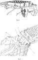
- the combination shown in Fig. 4 is fixed to the base 9 of the moveable armrest with storage box 12, as particularly shown in Fig. 5 .
- the shaft pin 6 is passed through the shaft sleeve 1 so as to extend through the base 9 and the armrest hinge 10 of the armrest box 12.
- the mounting bolts and nuts 8 are extend through the fitting holes 7 on the first and second extending portions 2b, 3b to secure the damping structure to the base 9 of the moveable armrest with storage box 12 so that the friction plate 2 and the metal hoop 3 are fastened without rotation.
- the gap between the shaft pin 6 and the shaft sleeve 1 is 0.05mm that can prevent abnormal noise. In this case, the shaft sleeve 1 rotates with the rotation of the plastic carrier 10.
- a manufacturing method of a new damping structure comprises the steps as follows:
- the method also includes providing the surface of the shaft sleeve 1 with a chrome plating layer.
Landscapes
- Engineering & Computer Science (AREA)
- General Engineering & Computer Science (AREA)
- Mechanical Engineering (AREA)
- Physics & Mathematics (AREA)
- Acoustics & Sound (AREA)
- Aviation & Aerospace Engineering (AREA)
- Vibration Dampers (AREA)
- Vibration Prevention Devices (AREA)
- Body Structure For Vehicles (AREA)
- Vehicle Body Suspensions (AREA)
Abstract
Description
- This invention relates to a damping structure, and more particularly to a novel damping structure and manufacturing method thereof.
- Damping structures are known to slow down the relative rotation of two parts (e.g. stationary part and rotating part), so as to maintain the rotation under a predetermined speed in some products. Taking a car's moveable armrest with storage box cover for example, when the lock is opened, the box cover will automatically open under the action of a spring. Then the damping structure will prevent the box cover from abrupt springing open. When the brake mechanism is released, the damping structure will prevent the box cover from rapidly closing due to its own weight and/or spring tension.
- However, the above mentioned damping structures usually only have the slow down effect, but cannot control the rotating part to stop at any position.
-
Patent document JP 200923575 - Patent document
CN 201320296282.5 - Although the above two patents both take stop effect, the metal clamping members, which act as the damping structure, are mainly made from steel or manganese material and shaped through casting, stamping, bending and other processes. Thus the clamping members produced in those ways have the following drawbacks: 1) although the clamping members formed through casting can ensure the thickness, but this kind of process results in low precision with a tolerance of about ± 1mm or more. In order to obtain a higher precision, it is necessary to conduct a secondary processing to clamping member, which leads to cost increasing and process complex. 2) The metal pieces produced by traditional casting, stamping and bending cannot eliminate the stress therein and thus the clamping members usually have internal plastic deformation stress. Only after overcoming the internal plastic deformation stress can the bolts and nuts adjust the clamping force. However, the internal plastic deformation stress is not fully reproducible, which leads to unstable clamping force adjusted by the bolts and nuts. 3) The rebound tolerance of the clamping member through stamping or bending molded process can only be controlled within ± 0.5mm. On the one hand, the stamping molding clamping member is thin, and thus is easily deformed when squeezed. Because of the form inaccuracy of their own resilience after bending, the tightening torque of bolts and nuts cannot be controlled; on the other hand, the clamping member has uniform thickness and thus cannot be partially thickened to increase the strength and stability, so it cannot steadily achieve hovering at any angle in practical applications.
- The object of this invention is to provide a novel damping structure and the manufacturing method thereof so as to achieve that the damping structure can steadily stop at any angle.
- According to one aspect of the invention, a novel damping structure is provided, comprising: an axially extending shaft sleeve, and a friction plate and a metal frame which are successively arranged outside of said shaft sleeve, said friction plate comprising a C-caped portion encircled said shaft sleeve and an extending portion of friction plate with up and down layers extending parallel to each other from both opposite edges of said first C-shaped portion, said metal frame being an extrusion member made of aluminum alloy or copper alloy and comprising a C-shaped portion of metal frame overlapped said first C-shaped portion of said friction plate and an extending portion of metal frame with up and down layers extending parallel to each other from both opposite edges of said second C-shaped portion, a fastener extending through said first extending portion and said second extending portion is provided for adjusting a pressing force between the friction plate and metal frame and thereby indirectly adjusting the friction force between said shaft sleeve and friction plate, a friction surface formed between said shaft sleeve and said friction plate.
- Preferably, said friction plate is made of polyoxymethylene plastic.
- Said shaft sleeve is made of stainless steel material.
- Preferably, the surface of said shaft sleeve is a chrome plating layer.
- The ports of the shaft sleeve extending out from the friction plate and the metal frame have a waist-shaped cross section separately.
- Said shaft sleeve has a through hole for receiving a shaft pin.
- Said fastener comprises a set of matched bolt and a locknut.
- A gap with a distance of 0.04-0.06 mm is maintained between said shaft pin and said shaft sleeve.
- The first and second extending portions are preferably further provided with a mounting hole through which the damping structure is connected to the element to which the damping structure is to be mounted by a conventional fixing means such as a screw; or more preferably, the first and second extending portions do not have a fitting hole, and the first and second extending portions are directly inserted into the element need to be mounted the damping structure.
- According to another aspect of the invention, a manufacturing method of a novel damping structure is provided, comprising: providing an axially extending shaft sleeve; providing a friction plate arranged outside of said shaft sleeve, which comprises C-caped portion encircled said shaft sleeve and an extending portion of friction plate with up and down layers extending in parallel to each other from both opposite edges of said first C-shaped portion; and providing a metal frame arranged outside of said friction plate made of aluminum alloy or copper alloy by an extrusion molding process, which comprises a C-shaped portion of metal frame encircled said first C-shaped portion of said friction plate and an extending portion of metal frame with up and down layers extending in parallel to each other from opposite edges of said second C-shaped portion; providing a fastener extending through said first extending portion and said second extend portion to adjust a pressing force between said shaft sleeve and friction plate, and a friction surface formed between said shaft sleeve and said friction plate.
- The metal frame is made from aluminum alloy or copper alloy through extrusion molding.
- Among them, the metal frame is an aluminum alloy or copper alloy extrusion member. In the conventional process, extrusion molding is a process in which thermoplastic polymers such as PS \ PMMA \ PC are stirred and mixed by an extruder screw in an extruder and molded to form. Such mold equipment for extrusion molding and forming cross-section is relatively simple and without interruptions, thus the method can improve the dimensional accuracy of the extrusion molding member and reduce the rejection rate. The low melting point of aluminum just meets the requirements of such extrusion process.
- The invention creatively utilizes the aluminum alloy to form the metal frame by the extrusion process, which retains the high stability and high precision of the extrusion process, such as, the precision can reach 0.05mm. The stably fixed metal frame ensures that the friction plate and shaft sleeve evenly contact with each other and thereby produces uniform friction force between shaft sleeve and friction plate. The invention retains low density characteristics of aluminum alloy, so that the metal frame is of lightweight. More important, the forming of the metal frame through the extrusion molding process releases the internal plastic deformation stress, so as to avoid the effect of the internal plastic deformation stress on the fastener for adjusting the pressing force, and thus to ensure the bolts and nuts can stably adjust the pressing force. The invention provides a damping structure with significant advantages over the prior art that safely achieves stopping at any angle.
- The slotted sleeve around the shaft in the damping structure plays a role to rub with the friction plate and produces a friction force. Since both ends of the shaft sleeve need to be fixed on other components so as to be driven by other parts to rub with friction plate, thus the shaft sleeve is required to be of high strength and not easily deformed.
- Therefore, this invention creatively uses a stainless steel material to manufacture a shaft sleeve, and preferably its surface is a chrome plating layer to increase the surface finish and abrasion resistance, further ensuring that the damping structure is uniformly rubbed during use.
-
-
Figure 1a is a schematic perspective view of a vehicle according to an exemplary embodiment; -
Figure 1b is a schematic perspective partial view of a vehicle interior according to an exemplary embodiment showed asFigure 1a ; -
Figure 2 is a schematic perspective view of a novel damping structure according to an exemplary embodiment of this invention; -
Figure 3 is an exploded view of an exemplary embodiment showed asFigure 2 ; -
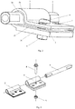
Figure 4 is a schematic perspective view of a combination of a damping structure as shown inFigure 2 mounted on a plastic carrier; -
Figure 5 is a schematic perspective view of a damping structure as shown inFig. 2 , which is mounted to the base of a moveable armrest with storage box. - The invention is described in further details with reference to specific embodiments below. It should be understood that the following examples are intended to illustrate the invention and are not intended to limit the scope of the invention.
- By way of example, but not limited, a novel damping structure provided by this invention is applied to an
automobile 100 shown inFig. 1a , in particular to thehandrail box 12 in the interior of theautomobile 100 as shown inFig. 1b . As shown inFigs. 2 and 3 , there is a novel damping structure according to a preferred embodiment of the invention comprising ashaft sleeve 1, afriction plate 2 and ametal frame 3 which are successively engaged from the inside to the outside. The two ports of theshaft sleeve 1 extending out from both ends of thefriction plate 2 and themetal frame 3 have a drop-shaped cross section for facilitating connection with other elements without relative rotation. Theshaft sleeve 1 has a through hole in that a shaft pin can be received so that the shaft sleeve can be easily connected to the element which needs to be assembled with the damping structure. Thefriction plate 2 includes a C-capedportion 2a engaging with theshaft sleeve 1 and an extending portion of friction plate 2b with up and down layers extending parallel to each other from opposite edges of the first C-shaped portion 2a. Themetal hoop 3 also includes a C-shaped portion ofmetal frame 3a that encloses the outer surface of the first C-shapedportion 2a of thefriction plate 2 and an extending portion of metal frame3b with up and down layers extending parallel to each other from opposite edges of the second C-shapedportion 3a. Wherein the first and second extendingportions 2b and 3b are clamped tightly by means of thebolt 4 and thelocknut 5 for adjusting the clamping force between themetal hoop 3 and thefriction plate 2 and further indirectly adjusting the friction between thefriction plate 2 and theshaft sleeve 1, which can provide a stable clamping force between every two components without loose after repeated use. The first and second extendingportions 2b, 3b are provided with fitting holes 7 for connecting the damping structure to the elements to be mounted through for example, bolts and nuts, screws and the like. - Wherein the
shaft sleeve 1 is made of a stainless steel material in order to provide a high finish on the surface of the shaft sleeve, and further preferably a chrome-plated surface. Thefriction plate 2 is made of polyoxymethylene plastic.Metal hoop 3 is an aluminum alloy or copper alloy extrusion member. Aluminum are molded through the extrusion process not only to provide high accuracy and stability, but also to maintain uniform pressure deformation so as to eliminate the internal plastic deformation stress and ensure the stability of compression force adjusted by bolt and nut. - Alternatively, the first and second extending
portions 2b, 3b are not provided with a fitting hole. The first andsecond extensions 2b, 3b are directly inserted into the components to be mounted by the damping structure when it is assembled. - As shown in
Fig. 4 , a damping structure according to a preferred embodiment of this invention is mounted to aplastic carrier 10. Firstly, theshaft sleeve 1 is inserted from one side into theplastic carrier 10, which requires the diameter of a hole in the initial insertion side of theplastic carrier 10 must be larger than the diameter of theshaft sleeve 1. Ananti-rotation sleeve 11 is hereby provided to preventshaft sleeve 1 from rotation at the insertion side, and then thebolt 4 and thelocknut 5 are screwed and tightened. - Next, the combination shown in
Fig. 4 is fixed to thebase 9 of the moveable armrest withstorage box 12, as particularly shown inFig. 5 . Theshaft pin 6 is passed through theshaft sleeve 1 so as to extend through thebase 9 and thearmrest hinge 10 of thearmrest box 12. Then the mounting bolts andnuts 8 are extend through the fitting holes 7 on the first and second extendingportions 2b, 3b to secure the damping structure to thebase 9 of the moveable armrest withstorage box 12 so that thefriction plate 2 and themetal hoop 3 are fastened without rotation. Wherein, the gap between theshaft pin 6 and theshaft sleeve 1 is 0.05mm that can prevent abnormal noise. In this case, theshaft sleeve 1 rotates with the rotation of theplastic carrier 10. Since thefriction plate 2 does not rotate with the rotation of thesleeve 1, a friction occurs between theshaft sleeve 1 and thefriction plate 2. When the friction torque between theshaft sleeve 1 and thefriction plate 2 is greater than the gravity torque at any angle of theplastic carrier 10 and the element mounted on it, theplastic carrier 10 will achieve hovering at any angle. - According to a preferred embodiment of this invention, a manufacturing method of a new damping structure is also provided, which comprises the steps as follows:
- a. Providing a
shaft sleeve 1; - b. Providing a
friction plate 2 encircled outside of theshaft sleeve 1, which comprises a C-capedportion 2a engaging with theshaft sleeve 1 and an extending portion of friction plate 2b with up and down layers extending in parallel to each other from opposite edges of the first C-shapedportion 2a; - c. Providing a
metal hoop 3 overlapped outside of thefriction plate 2 by an extrusion molding using an aluminum alloy, which comprises a C-shaped portion ofmetal frame 3a engaging with the first C-shapedportion 2a of thefriction plate 2 and an extending portion ofmetal frame 3b with up and down layers extending in parallel to each other from both opposite edges of the second C-shapedportion 3a; and - d. Providing a fastener extending through the first extending portion 2b and the second extending
portion 3b to adjust the pressing force between theshaft sleeve 1 and thefriction plate 2, and a friction surface is formed between theshaft sleeve 1 and thefriction plate 2. - The method also includes providing the surface of the
shaft sleeve 1 with a chrome plating layer. - According to this invention, it is provided with a novel damping structure which provides an uniform frictional force between the shaft sleeve and the friction plate, achieves hovering at any angle and thus provides a damping structure with significant advantages over the prior art.
- The afore mentioned preferable embodiments are only exemplary rather than limiting in nature, and many variations of the present invention are possible in light of the above teachings. It is, therefore, to be understood that all easy, equivalent variations and modifications made according to the claims and description of present invention come within the scope of the invention as defined by the claims. The contents that have not been described in detail are the routine technical solutions.
Claims (10)
- A novel damping structure, comprising: an shaft sleeve (1), and a friction plate (2) and a metal frame (3) which are successively arranged outside of said shaft sleeve (1), said friction plate (2) comprising C-caped portion(2a) encircled said shaft sleeve (1) and an extending portion of friction plate (2b) with up and down layers extending parallel to each other from both opposite edges of said first C-shaped portion (2a), said metal frame (3) being an extrusion member made of aluminum alloy or copper alloy and comprising a C-shaped portion of metal frame(3a) overlapped said first C-shaped portion (2a) of said friction plate (2) and an extending portion of metal frame(3b) with up and down layers extending parallel to each other from both opposite edges of said second C-shaped portion (3a), a fastener extending through said first extending portion (2b) and said second extending portion (3b) is provided for adjusting a pressing force between the friction plate (2) and metal frame (3) and thereby indirectly adjusting the friction force between said shaft sleeve (1) and friction plate (2), a friction surface formed between said shaft sleeve (1) and said friction plate (2).
- The novel damping structure according to claim 1, characterized in that said friction plate (2) is made of polyoxymethylene plastic.
- The novel damping structure according to claim 1, characterized in that said shaft sleeve (1) is made of stainless steel material.
- The novel damping structure according to claim 3, characterized in that the surface of said shaft sleeve (1) is a chrome plating layer.
- The novel damping structure according to claim 1, characterized in that the ports of the shaft sleeve (1) extending out from the friction plate (2) and the metal frame (3) have a waist-shaped cross section separately.
- The novel damping structure according to claim 1 or 5, characterized in that said shaft sleeve (1) has a through hole for receiving a shaft pin (6).
- The novel damping structure according to claim 1, characterized in that said fastener comprises a set of matched bolt (4) and a locknut (5).
- The novel damping structure according to claim 1, characterized in that a gap with a distance of 0.04-0.06 mm is maintained between said shaft pin (6) and said shaft sleeve (1).
- A manufacturing method of a novel damping structure comprising:- providing a shaft sleeve (1);- providing a friction plate (2) arranged outside of said shaft sleeve (1), which comprises C-caped portion (2a) encircled said shaft sleeve and an extending portion of friction plate (2b) with up and down layers extending in parallel to each other from both opposite edges of said first C-shaped portion (2a); and- providing a metal frame (3) arranged outside of said friction plate (2) made of aluminum alloy or copper alloy by an extrusion molding process, which comprises a C-shaped portion of metal frame (3a) encircled said first C-shaped portion (2a) of said friction plate (2) and an extending portion of metal frame (3b) with up and down layers extending in parallel to each other from opposite edges of said second C-shaped portion (3a); and- providing a fastener extending through said first extending portion (2b) and said second extend portion (3b) to adjust a pressing force between said shaft sleeve (1) and friction plate (2), and a friction surface formed between said shaft sleeve (1) and said friction plate (2).
- The manufacturing method according to claim 9, characterized in that further including providing a surface of said shaft sleeve (1) as a chrome plating layer.
Applications Claiming Priority (2)
| Application Number | Priority Date | Filing Date | Title |
|---|---|---|---|
| CN201410472522.1A CN104265831B (en) | 2014-09-16 | 2014-09-16 | A kind of damping structure and building method thereof |
| PCT/CN2015/089717 WO2016041494A1 (en) | 2014-09-16 | 2015-09-16 | Novel damping structure and construction method thereof |
Publications (2)
| Publication Number | Publication Date |
|---|---|
| EP3228900A1 true EP3228900A1 (en) | 2017-10-11 |
| EP3228900A4 EP3228900A4 (en) | 2018-02-28 |
Family
ID=52157387
Family Applications (1)
| Application Number | Title | Priority Date | Filing Date |
|---|---|---|---|
| EP15842222.0A Withdrawn EP3228900A4 (en) | 2014-09-16 | 2015-09-16 | Novel damping structure and construction method thereof |
Country Status (4)
| Country | Link |
|---|---|
| US (1) | US20170320443A1 (en) |
| EP (1) | EP3228900A4 (en) |
| CN (1) | CN104265831B (en) |
| WO (1) | WO2016041494A1 (en) |
Families Citing this family (9)
| Publication number | Priority date | Publication date | Assignee | Title |
|---|---|---|---|---|
| CN104265831B (en) * | 2014-09-16 | 2016-09-21 | 上海延锋金桥汽车饰件系统有限公司 | A kind of damping structure and building method thereof |
| EP3103555B1 (en) * | 2015-06-12 | 2018-05-09 | Sigma Laborzentrifugen GmbH | Laboratory centrifuge with damping device |
| CN106166738B (en) * | 2016-09-23 | 2019-01-25 | 苏州哈工易科机器人有限公司 | A kind of teach-by-doing dragging can hover teaching robot |
| CN108412346A (en) * | 2018-05-09 | 2018-08-17 | 上海球明标准件有限公司 | A kind of Automobile Dashboard handrail hinge assembly with hovering function |
| CN109057596A (en) * | 2018-07-20 | 2018-12-21 | 富诚汽车零部件有限公司 | A kind of adjustable handrail linkage |
| CN109488141A (en) * | 2018-12-27 | 2019-03-19 | 上海球明标准件有限公司 | It is a kind of with hovering function connection on lower body handrail hinge assembly |
| CN112647788B (en) * | 2020-12-30 | 2022-07-12 | 浙江鼎立实业有限公司 | Electric parking door hinge |
| CN114379762B (en) * | 2022-01-21 | 2024-05-10 | 中国商用飞机有限责任公司 | Adjustable damping hinge structure |
| US20250163739A1 (en) * | 2023-11-17 | 2025-05-22 | Yu Zhou | Mute hinge |
Family Cites Families (10)
| Publication number | Priority date | Publication date | Assignee | Title |
|---|---|---|---|---|
| US2999718A (en) * | 1959-09-17 | 1961-09-12 | Handler Frank | Sun visor |
| DE19754533A1 (en) * | 1997-12-09 | 1999-06-10 | Johnson Contr Interiors Gmbh | Sun visor axis |
| KR100446902B1 (en) * | 2001-12-27 | 2004-09-04 | 엘지전자 주식회사 | The hinge structure of plane-type display device |
| JP2003248527A (en) * | 2002-02-22 | 2003-09-05 | Sando Kogyosho:Kk | Rotation suppression mechanism and hinge |
| JP2009023575A (en) * | 2007-07-23 | 2009-02-05 | Sando Kogyosho:Kk | Lid opening / closing device |
| KR101544303B1 (en) * | 2011-08-31 | 2015-08-12 | 스가쓰네 고우교 가부시키가이샤 | Rotary damper and hinge device with damper |
| CN103104163A (en) * | 2011-11-15 | 2013-05-15 | 王广武 | Combined-corner adjustable door-and-window sleeve and installation method thereof |
| CN203335619U (en) * | 2013-05-27 | 2013-12-11 | 延锋伟世通汽车饰件系统有限公司 | Stoppable circumference friction type mechanism |
| CN104265831B (en) * | 2014-09-16 | 2016-09-21 | 上海延锋金桥汽车饰件系统有限公司 | A kind of damping structure and building method thereof |
| CN204175865U (en) * | 2014-09-16 | 2015-02-25 | 延锋汽车饰件系统有限公司 | A kind of New Damping structure |
-
2014
- 2014-09-16 CN CN201410472522.1A patent/CN104265831B/en not_active Expired - Fee Related
-
2015
- 2015-09-16 WO PCT/CN2015/089717 patent/WO2016041494A1/en not_active Ceased
- 2015-09-16 EP EP15842222.0A patent/EP3228900A4/en not_active Withdrawn
-
2017
- 2017-07-24 US US15/657,376 patent/US20170320443A1/en not_active Abandoned
Also Published As
| Publication number | Publication date |
|---|---|
| CN104265831B (en) | 2016-09-21 |
| WO2016041494A1 (en) | 2016-03-24 |
| CN104265831A (en) | 2015-01-07 |
| US20170320443A1 (en) | 2017-11-09 |
| EP3228900A4 (en) | 2018-02-28 |
Similar Documents
| Publication | Publication Date | Title |
|---|---|---|
| EP3228900A1 (en) | Novel damping structure and construction method thereof | |
| US8875348B2 (en) | Friction hinge system | |
| US8511194B2 (en) | Transmission drive unit | |
| US11479995B2 (en) | Fastening device for fastening a first component to a second component | |
| US20110002565A1 (en) | Bearing bush | |
| US20130305503A1 (en) | Torque assembly and method of manufacture | |
| CN104870845B (en) | Rolling bearing arrangement and method for producing a rolling bearing | |
| CN101180471A (en) | Assembly of plain bearings, plain bearing systems and plain bearing systems | |
| FR3039229A1 (en) | POSITIONING DEVICES WITH TOLERANCE COMPENSATION, AUTOMOTIVE COMPONENT ASSEMBLY COMPRISING SUCH A DEVICE, AND POSITIONING METHOD WITH TOLERANCE COMPENSATION | |
| US20180044139A1 (en) | Drag rollers for escalators, moving walkways, and other conveyors | |
| KR20130026989A (en) | Vehicle body | |
| US9512875B2 (en) | Bearing unit | |
| US20190169897A1 (en) | Vehicle interior component | |
| US8448749B2 (en) | Lubricating apparatus for follower bearing | |
| EP2667042A1 (en) | Fastening method and fastening device | |
| EP2973955B1 (en) | Windscreen wiper motor | |
| DE112015007088T5 (en) | wheel assembly | |
| US10487552B2 (en) | Motor vehicle hinge | |
| CN204175865U (en) | A kind of New Damping structure | |
| EP4030081A1 (en) | Toothed pulley | |
| CN214499745U (en) | Output shaft assembly with injection molding bearing and motor applying output shaft assembly | |
| US9855901B1 (en) | Flange for exterior ornamentation | |
| JP3859526B2 (en) | Female thread | |
| CN113324014A (en) | Gear housing unit with clamping screw for axial play compensation | |
| JP2004042561A (en) | Insert molded item and its production method |
Legal Events
| Date | Code | Title | Description |
|---|---|---|---|
| PUAI | Public reference made under article 153(3) epc to a published international application that has entered the european phase |
Free format text: ORIGINAL CODE: 0009012 |
|
| 17P | Request for examination filed |
Effective date: 20170418 |
|
| AK | Designated contracting states |
Kind code of ref document: A1 Designated state(s): AL AT BE BG CH CY CZ DE DK EE ES FI FR GB GR HR HU IE IS IT LI LT LU LV MC MK MT NL NO PL PT RO RS SE SI SK SM TR |
|
| AX | Request for extension of the european patent |
Extension state: BA ME |
|
| DAV | Request for validation of the european patent (deleted) | ||
| DAX | Request for extension of the european patent (deleted) | ||
| A4 | Supplementary search report drawn up and despatched |
Effective date: 20180125 |
|
| RIC1 | Information provided on ipc code assigned before grant |
Ipc: F16F 7/06 20060101ALI20180119BHEP Ipc: F16F 7/02 20060101ALI20180119BHEP Ipc: F16F 15/12 20060101AFI20180119BHEP |
|
| STAA | Information on the status of an ep patent application or granted ep patent |
Free format text: STATUS: THE APPLICATION IS DEEMED TO BE WITHDRAWN |
|
| 18D | Application deemed to be withdrawn |
Effective date: 20180824 |