EP3228894A1 - Clutch actuation mechanism - Google Patents
Clutch actuation mechanism Download PDFInfo
- Publication number
- EP3228894A1 EP3228894A1 EP16164473.7A EP16164473A EP3228894A1 EP 3228894 A1 EP3228894 A1 EP 3228894A1 EP 16164473 A EP16164473 A EP 16164473A EP 3228894 A1 EP3228894 A1 EP 3228894A1
- Authority
- EP
- European Patent Office
- Prior art keywords
- clutch
- disc
- pin
- spring
- contacting surface
- Prior art date
- Legal status (The legal status is an assumption and is not a legal conclusion. Google has not performed a legal analysis and makes no representation as to the accuracy of the status listed.)
- Withdrawn
Links
Images


Classifications
-
- F—MECHANICAL ENGINEERING; LIGHTING; HEATING; WEAPONS; BLASTING
- F16—ENGINEERING ELEMENTS AND UNITS; GENERAL MEASURES FOR PRODUCING AND MAINTAINING EFFECTIVE FUNCTIONING OF MACHINES OR INSTALLATIONS; THERMAL INSULATION IN GENERAL
- F16D—COUPLINGS FOR TRANSMITTING ROTATION; CLUTCHES; BRAKES
- F16D23/00—Details of mechanically-actuated clutches not specific for one distinct type
- F16D23/12—Mechanical clutch-actuating mechanisms arranged outside the clutch as such
- F16D23/14—Clutch-actuating sleeves or bearings; Actuating members directly connected to clutch-actuating sleeves or bearings
- F16D23/143—Arrangements or details for the connection between the release bearing and the diaphragm
- F16D23/144—With a disengaging thrust-ring distinct from the release bearing, and secured to the diaphragm
- F16D23/146—Arrangements for the connection between the thrust-ring and the release bearing
-
- F—MECHANICAL ENGINEERING; LIGHTING; HEATING; WEAPONS; BLASTING
- F16—ENGINEERING ELEMENTS AND UNITS; GENERAL MEASURES FOR PRODUCING AND MAINTAINING EFFECTIVE FUNCTIONING OF MACHINES OR INSTALLATIONS; THERMAL INSULATION IN GENERAL
- F16D—COUPLINGS FOR TRANSMITTING ROTATION; CLUTCHES; BRAKES
- F16D23/00—Details of mechanically-actuated clutches not specific for one distinct type
- F16D23/12—Mechanical clutch-actuating mechanisms arranged outside the clutch as such
-
- F—MECHANICAL ENGINEERING; LIGHTING; HEATING; WEAPONS; BLASTING
- F16—ENGINEERING ELEMENTS AND UNITS; GENERAL MEASURES FOR PRODUCING AND MAINTAINING EFFECTIVE FUNCTIONING OF MACHINES OR INSTALLATIONS; THERMAL INSULATION IN GENERAL
- F16D—COUPLINGS FOR TRANSMITTING ROTATION; CLUTCHES; BRAKES
- F16D13/00—Friction clutches
- F16D13/58—Details
- F16D13/75—Features relating to adjustment, e.g. slack adjusters
- F16D13/752—Features relating to adjustment, e.g. slack adjusters the adjusting device being located in the actuating mechanism arranged outside the clutch
-
- F—MECHANICAL ENGINEERING; LIGHTING; HEATING; WEAPONS; BLASTING
- F16—ENGINEERING ELEMENTS AND UNITS; GENERAL MEASURES FOR PRODUCING AND MAINTAINING EFFECTIVE FUNCTIONING OF MACHINES OR INSTALLATIONS; THERMAL INSULATION IN GENERAL
- F16D—COUPLINGS FOR TRANSMITTING ROTATION; CLUTCHES; BRAKES
- F16D27/00—Magnetically- or electrically- actuated clutches; Control or electric circuits therefor
- F16D27/10—Magnetically- or electrically- actuated clutches; Control or electric circuits therefor with an electromagnet not rotating with a clutching member, i.e. without collecting rings
- F16D27/108—Magnetically- or electrically- actuated clutches; Control or electric circuits therefor with an electromagnet not rotating with a clutching member, i.e. without collecting rings with axially movable clutching members
- F16D27/112—Magnetically- or electrically- actuated clutches; Control or electric circuits therefor with an electromagnet not rotating with a clutching member, i.e. without collecting rings with axially movable clutching members with flat friction surfaces, e.g. discs
-
- F—MECHANICAL ENGINEERING; LIGHTING; HEATING; WEAPONS; BLASTING
- F16—ENGINEERING ELEMENTS AND UNITS; GENERAL MEASURES FOR PRODUCING AND MAINTAINING EFFECTIVE FUNCTIONING OF MACHINES OR INSTALLATIONS; THERMAL INSULATION IN GENERAL
- F16D—COUPLINGS FOR TRANSMITTING ROTATION; CLUTCHES; BRAKES
- F16D28/00—Electrically-actuated clutches
-
- F—MECHANICAL ENGINEERING; LIGHTING; HEATING; WEAPONS; BLASTING
- F16—ENGINEERING ELEMENTS AND UNITS; GENERAL MEASURES FOR PRODUCING AND MAINTAINING EFFECTIVE FUNCTIONING OF MACHINES OR INSTALLATIONS; THERMAL INSULATION IN GENERAL
- F16D—COUPLINGS FOR TRANSMITTING ROTATION; CLUTCHES; BRAKES
- F16D23/00—Details of mechanically-actuated clutches not specific for one distinct type
- F16D23/12—Mechanical clutch-actuating mechanisms arranged outside the clutch as such
- F16D2023/123—Clutch actuation by cams, ramps or ball-screw mechanisms
-
- F—MECHANICAL ENGINEERING; LIGHTING; HEATING; WEAPONS; BLASTING
- F16—ENGINEERING ELEMENTS AND UNITS; GENERAL MEASURES FOR PRODUCING AND MAINTAINING EFFECTIVE FUNCTIONING OF MACHINES OR INSTALLATIONS; THERMAL INSULATION IN GENERAL
- F16D—COUPLINGS FOR TRANSMITTING ROTATION; CLUTCHES; BRAKES
- F16D23/00—Details of mechanically-actuated clutches not specific for one distinct type
- F16D23/12—Mechanical clutch-actuating mechanisms arranged outside the clutch as such
- F16D2023/126—Actuation by rocker lever; Rocker levers therefor
-
- F—MECHANICAL ENGINEERING; LIGHTING; HEATING; WEAPONS; BLASTING
- F16—ENGINEERING ELEMENTS AND UNITS; GENERAL MEASURES FOR PRODUCING AND MAINTAINING EFFECTIVE FUNCTIONING OF MACHINES OR INSTALLATIONS; THERMAL INSULATION IN GENERAL
- F16D—COUPLINGS FOR TRANSMITTING ROTATION; CLUTCHES; BRAKES
- F16D2300/00—Special features for couplings or clutches
- F16D2300/18—Sensors; Details or arrangements thereof
Definitions
- the invention relates to a clutch actuation mechanism for actuating a clutch operating means of a spring loaded friction clutch.
- the clutch actuation mechanism has a motor driven rotary disc for being connected to the clutch operating means to actuate the clutch operating means by a rotation of the disc around a disc's rotary axis.
- a clutch is a device for selectively coupling an input shaft with an output shaft, i.e. to engage or disengage transmission of torque and thus power between the input shaft and the output shaft.
- the closed state the input shaft and the output shaft are couple in a torque transmitting manner (i.e. the clutch transmits any torque being below its maximum specified torque).
- the open state the shafts are decoupled and torque transmission between the two shafts does not take place.
- the input shaft and the output shaft of the clutch can rotate independently of each other.
- a friction clutch may slip, this means that the clutch may transmit only a fraction of the torque being delivered to the input shaft to the output shaft. Slipping enables, e.g. to couple the two shafts smoothly if they rotate with different rotational speed.
- friction clutches enable to connect or disconnect the engine output shaft (usually the crank shaft) with the transmission gear input shaft.
- These friction clutches typically have a clutch disk (or a differently shaped clutch device) being connected to one of the two shafts (mostly to a clutch input shaft, often being at the same time the engine output shaft) in a torque transmitting manner.
- the clutch disc is axially movable by means of a clutch operating means (e.g. a clutch lever, a push rod, a pull rod, a Bowden cable or the like) and a clutch spring loads the clutch disk towards a driver.
- the driver is commonly called clutch bell, and we will use the terms interchangeably. Due to the friction between the clutch disc and the clutch bell a torque can be transmitted between the first and second shaft.
- a clutch operating means like e.g. clutch lever is connected to the clutch disc enabling to move the clutch disc away from the clutch bell, thereby opening the clutch, i.e. disconnecting the two shafts. If one releases the lever (the clutch operating means), the spring pushes the clutch against the clutch bell and the two shafts are torque transmittingly connected.
- the clutch operating means is typically mechanically connected with a clutch pedal, enabling a driver to actuate the clutch lever with one of his feet, typically using the left feet.
- the clutch pedal In drive by wire applications the clutch pedal is not mechanically coupled to the clutch operating means, instead the clutch operating means has to be actuated by a motor in response to a sensor's signal, e.g. a clutch pedal deflection sensor.
- a sensor's signal e.g. a clutch pedal deflection sensor.
- this is easy, but a problem in driving the clutch lever is that its force versus deflection curve is not linear and has a pronounced maximum in between of the positions where clutch engages and disengages, respectively. Beyond, the force being required to open a clutch can be significant and is often in the range of a few kN.
- the problem to be solved by the invention is to provide a simple and reliable clutch actuation mechanism.
- the clutch actuation mechanism for actuating a clutch operating means of a spring loaded friction clutch comprises at least a rotary disc for being connected to the clutch operating means.
- the connection can be provided e.g. by push rod being pivoting connected to the disc and to the clutch operating means.
- Other types of connecting the disc with the clutch operating means can be used as well, e.g. a Bowden cable, a hydraulic actuator or the like.
- the disc may provide a cam (or being connected to a cam disc or cam shaft) for pushing a clutch operating means against the force being provided by the clutch spring.
- the disc does not need to be a full disc, it can as well be a disc segment to thereby reduce the weight and the size of the clutch actuation mechanism.
- the disc is a rotary disc. This means it is rotatable supported to enable a rotation of the disc around a disc's rotary axis, e.g. by a radial bearing.
- a motor is coupled to drive the rotation of the disc, in other words the motor may provide a first torque M m to the disc, contributing to a rotation of the disc.
- the disc comprises a pin being attached to the disc with an offset r from the disc's rotary axis. If the disc rotates, the pin provides a circular path with a radius r. Accordingly, the disc's rotary axis and the pin define a vector from the rotary axis to the pin is referred to as r (r is used to indicate the corresponding scalar, i.e. the length of the vector).
- a lever is pivoting supported to pivot around a lever's pivot axis.
- the pivot axis and the disc's rotary axis are at least essentially parallel ( ⁇ 5°).
- the lever has a contacting surface being pushed against the pin, to thereby provide a second torque to the disc.
- a spring forces the lever with its contacting surface against the pin.
- the pin travels over the contacting surface.
- the lever arm d l of the lever transmitting the spring force via the pin to the disc, thus changes during the rotation and enables to adapt the additional torque being provided to the disc to compensate at least in part for the non-constant force being required to actuate the clutch via the clutch operating means.
- the torque required to be provided by the motor can be kept low and almost constant. This enables to reduce the power required by the motor and as well the motor's weight.
- the transmission coupling the motor to the disc can be lighter (and thus cheaper) as well.
- the motor shaft has a pinion engaging to gear teeth of the disc, but other more complex transmissions may be used as well.
- the contacting surface is curved. This enables to even better adapt the torque M l provided via the lever to disc to the torque required to operate the clutch operating means.
- the first tangent is the tangent of the contacting surface at the position where contacting surface contacts the pin.
- a 'second tangent' is defined by the traveling path of the pin, again at the position where the pin contacts contacting surface. These two tangents intersect at an angle ⁇ at the point where the pin contacts the contacting surface (if the pin's diameter is neglected).
- M C ( ⁇ ) (briefly M C ) is the torque ( ⁇ 20%, preferably ⁇ 10%, or even more preferred ⁇ 5% or even less) required to compensate the clutch spring as a function of ⁇ .
- ⁇ is the angle between the radial direction being defined by the pin's center and the ray starting at the rotary axis through the pivot axis.
- ⁇ ⁇ is an boundary that should be kept low, e.g. ⁇ ⁇ ⁇ 10°, preferably ⁇ ⁇ ⁇ 5°, even more preferred ⁇ ⁇ ⁇ 1°.
- F 0 is the force provided by the spring to the lever at a lever arm d S from the pivot axis (as usual the length of vector will be represented by omitting the arrow), k is the spring's constant and ⁇ l the extension of the spring relative to the length l 0 , where the spring provides F 0 Only for simplicity, F 0 , k and ⁇ l should be at least approximately parallel ( ⁇ 10°) and at least approximately orthogonal ( ⁇ 10°) to d S Deviations from the orthogonality can be compensated by replacing ( F 0 + k • ⁇ l ) d s by ( F 0 + k ⁇ ⁇ l ) d s sin ⁇ , wherein ⁇ is the angle between the force F S provided by the spring and the lever arm d S .
- ⁇ Arcsin ⁇ M C r 2 sin 2 ⁇ + d min + r 1 ⁇ cos ⁇ 2 r F 0 + k ⁇ ⁇ l ⁇ d S ⁇ sin ⁇ ⁇ ⁇ ⁇ ⁇ ,
- the pin is rotatable supported by the disc, this reduces friction and thus the response of the clutch to controls provided to the motor (e.g. via a control unit) is more direct as breakaway torque is reduced.
- the clutch actuation comprises a support structure supporting at least the (radial) bearing of the disc, the pivotable support mechanism of the lever and the motor.
- the constraining forces are thus as far as possible adsorbed the support structure.
- the support structure may be attached to the clutch housing, a clutch support or the like, to thereby provide a closed linkage of the components.
- the motor is an electro motor being coupled to the disc via a reduction gear.
- the motor's torque is not amplified by the spring, this is advantageous e.g. at angles ⁇ at which M C ( ⁇ ) is rather low or essentially vanishes (i.e. M C ( ⁇ )) .
- M C ⁇ ⁇ 1 3 Max M C preferably M C ⁇ ⁇ 1 10 Max M C , wherein Max ( M C ( ⁇ )) is the maximum of M C to compensate for the clutch spring.
- ⁇ is selected to overcompensate the torque required to compensate the clutch spring, if the clutch operating means are in a position where the clutch is open and/or closed. This enables to shut the motor in the respective end positions off and the corresponding end position (clutch open or closed) is maintained. In other words, the clutch actuation mechanism renders the clutch bistable. No energy is wasted to maintain the clutch open or closed, respectively.
- Selecting ⁇ as suggested is simple, simply replace M C ( ⁇ open ) and/or M C ( ⁇ closed ) by a slightly bigger (neglecting a potential sign) value for the angles ⁇ open or ⁇ closed which correspond to the open or closed position, respectively.
- the disc could be reduced to a lever being rotatable supported. But the term 'lever' is required for another item of the clutch actuation mechanism being distinct from the disc.
- the term 'disc' has been chosen only to enhance readability. One could as well replace the term disc by 'first lever' and the term lever by 'second lever'.
- FIG 1 a preferred embodiment of a clutch actuation mechanism is shown.
- the clutch operating mechanism has a support 80, being symbolized by a frame.
- the support 80 supports a motor 30 driving a disc 10 via a symbolized reduction gear 40.
- the motor 30 could as well drive the disc 10 via a shaft or directly, but the reduction gear 40 is a preferred alternative.
- the motor is preferably an electric motor.
- the disc 10 is rotatable supported relative to the support, enabling a rotation of the disc 10 around its rotary axis 11.
- the disc 10 is represented by a disc segment 10 with a disc extension 19.
- the disc extension 19 and the disc 10 can be made of a single piece, i.e. form a unitary piece.
- a clutch operating means 3, here in the form of a push rod is connected to the disc 10 at a distance d o , thus the lever arm is d S .
- Advancing or retracting the clutch operating means 3 enables to open or close the clutch 90.
- the clutch operating means 3 transmits a force F C required to open the clutch.
- the clutch 90 has an input shaft 91 and an output shaft 92 which can be connected enabling a torque transmission between said two shafts 91, 92.
- an additional torque is provided by a spring 4 via a lever 20.
- the lever 20 is pivotable supported by the support 80.
- the lever's pivot axis 21 is at least essentially parallel ( ⁇ 5°) to the rotary axis 11 of the disc 10.
- the spring 4 presses a curved contacting surface 22 of the lever 20 against a pin 12 being connected to the disc 10 at distance r from the rotary axis 11.
- the additional torque M l provided to the disc 10 depends on the force F S provided by the spring to the lever 20 at the lever arm d S the angle of attack of the lever 20 to the pin 12 and the lever arm d l of the lever 20 relative to the pin 12.
- FIG. 2 shows a simplified picture of a similar clutch actuation mechanism making use of the same principle.
- a lever 20 with a first lever arm d S is forced by a spring force F S against a pin 12, being rotatable with a rotary axis 11.
- the pin 12 may thus travel along a circular path 13.
- the vector r indicates the lever arm of the pin 12.
- the pin 12 travels over the contacting surface 22 when the disc 10 and thus the vector r rotates.
Landscapes
- Engineering & Computer Science (AREA)
- General Engineering & Computer Science (AREA)
- Mechanical Engineering (AREA)
- Physics & Mathematics (AREA)
- Electromagnetism (AREA)
- Mechanical Operated Clutches (AREA)
Abstract
A clutch actuation mechanism for actuating a clutch operating means 3 of a spring loaded friction clutch comprising at least a motor driven rotary disc 10 for being connected to the clutch operating means 3 enables to operate the motor with an essentially constant and reduced torque, if a pin 12 is attached to the disc 10 with an offset r from the disc's rotary axis 11, and if a lever 20 has a curved contacting surface 22 and if a spring forces the lever 20 with its contacting surface 22 against the pin 12 to thereby provide an additional torque to the disc 10. Thus, the pin 12 travels over the contacting surface 22 when the disc 10 rotates to open or close the spring loaded clutch via the clutch operating means and the curvature enables to adapt the torque provided by the spring to the torque required to compensate for the clutch spring.
Description
- The invention relates to a clutch actuation mechanism for actuating a clutch operating means of a spring loaded friction clutch. The clutch actuation mechanism has a motor driven rotary disc for being connected to the clutch operating means to actuate the clutch operating means by a rotation of the disc around a disc's rotary axis.
- A clutch is a device for selectively coupling an input shaft with an output shaft, i.e. to engage or disengage transmission of torque and thus power between the input shaft and the output shaft. One as well uses the terminology to close (=engage) or open (=disengage) a clutch. In the closed state, the input shaft and the output shaft are couple in a torque transmitting manner (i.e. the clutch transmits any torque being below its maximum specified torque). In the open state, the shafts are decoupled and torque transmission between the two shafts does not take place. In other words the input shaft and the output shaft of the clutch can rotate independently of each other. In between of these two states, a friction clutch may slip, this means that the clutch may transmit only a fraction of the torque being delivered to the input shaft to the output shaft. Slipping enables, e.g. to couple the two shafts smoothly if they rotate with different rotational speed.
- In particular in automotive applications, friction clutches enable to connect or disconnect the engine output shaft (usually the crank shaft) with the transmission gear input shaft. These friction clutches typically have a clutch disk (or a differently shaped clutch device) being connected to one of the two shafts (mostly to a clutch input shaft, often being at the same time the engine output shaft) in a torque transmitting manner. The clutch disc is axially movable by means of a clutch operating means (e.g. a clutch lever, a push rod, a pull rod, a Bowden cable or the like) and a clutch spring loads the clutch disk towards a driver. Said driver is torque transmittingly connected to the second of said shafts, typically the transmission gear input shaft (=clutch output shaft). The driver is commonly called clutch bell, and we will use the terms interchangeably. Due to the friction between the clutch disc and the clutch bell a torque can be transmitted between the first and second shaft. A clutch operating means like e.g. clutch lever is connected to the clutch disc enabling to move the clutch disc away from the clutch bell, thereby opening the clutch, i.e. disconnecting the two shafts. If one releases the lever (the clutch operating means), the spring pushes the clutch against the clutch bell and the two shafts are torque transmittingly connected. The clutch operating means is typically mechanically connected with a clutch pedal, enabling a driver to actuate the clutch lever with one of his feet, typically using the left feet.
- In drive by wire applications the clutch pedal is not mechanically coupled to the clutch operating means, instead the clutch operating means has to be actuated by a motor in response to a sensor's signal, e.g. a clutch pedal deflection sensor. In principle this is easy, but a problem in driving the clutch lever is that its force versus deflection curve is not linear and has a pronounced maximum in between of the positions where clutch engages and disengages, respectively. Beyond, the force being required to open a clutch can be significant and is often in the range of a few kN.
- It has been suggested in
DE 197 10 365 C2 to actuate a clutch with an electric motor, driving a worm drive via a friction clutch. The threaded spindle of the worm drive engages with a gear wheel. The gear wheel is connected to a rotary cam with a pin being offset from the rotational axis of the gear wheel. The pin engages with a push rod for actuating a clutch disc. Thus, depending on the direction of rotation of the electric motor, the push rod can be advanced or retracted. To reduce the torque required to rotate the threaded spindle, a spring is coupled with the rotary cam to store potential energy when closing the clutch. This potential energy is used to support the motor when opening the clutch at a later point of time. - The problem to be solved by the invention is to provide a simple and reliable clutch actuation mechanism.
- Solutions of the problem are described in the independent claims. The dependent claims relate to further improvements of the invention.
- The clutch actuation mechanism for actuating a clutch operating means of a spring loaded friction clutch comprises at least a rotary disc for being connected to the clutch operating means. The connection can be provided e.g. by push rod being pivoting connected to the disc and to the clutch operating means. Other types of connecting the disc with the clutch operating means can be used as well, e.g. a Bowden cable, a hydraulic actuator or the like. For example the disc may provide a cam (or being connected to a cam disc or cam shaft) for pushing a clutch operating means against the force being provided by the clutch spring. The disc does not need to be a full disc, it can as well be a disc segment to thereby reduce the weight and the size of the clutch actuation mechanism.
- As indicated above the disc is a rotary disc. This means it is rotatable supported to enable a rotation of the disc around a disc's rotary axis, e.g. by a radial bearing. A motor is coupled to drive the rotation of the disc, in other words the motor may provide a first torque Mm to the disc, contributing to a rotation of the disc.
- The disc comprises a pin being attached to the disc with an offset r from the disc's rotary axis. If the disc rotates, the pin provides a circular path with a radius r. Accordingly, the disc's rotary axis and the pin define a vector from the rotary axis to the pin is referred to as
r (r is used to indicate the corresponding scalar, i.e. the length of the vector). - A lever is pivoting supported to pivot around a lever's pivot axis. The pivot axis and the disc's rotary axis are at least essentially parallel (±5°). The lever has a contacting surface being pushed against the pin, to thereby provide a second torque to the disc. To this end, a spring forces the lever with its contacting surface against the pin. As the disc rotates to open and close the spring loaded clutch via the clutch operating means, the pin travels over the contacting surface. The lever arm dl of the lever transmitting the spring force via the pin to the disc, thus changes during the rotation and enables to adapt the additional torque being provided to the disc to compensate at least in part for the non-constant force being required to actuate the clutch via the clutch operating means. Thus, the torque required to be provided by the motor can be kept low and almost constant. This enables to reduce the power required by the motor and as well the motor's weight. In addition, the transmission coupling the motor to the disc can be lighter (and thus cheaper) as well. In the simplest case, the motor shaft has a pinion engaging to gear teeth of the disc, but other more complex transmissions may be used as well.
- In a preferred embodiment, the contacting surface is curved. This enables to even better adapt the torque Ml provided via the lever to disc to the torque required to operate the clutch operating means. As the pin contacts the contacting surface at a varying position this defines a so called 'first tangent' of the contacting surface, or in other words the first tangent is the tangent of the contacting surface at the position where contacting surface contacts the pin. A 'second tangent' is defined by the traveling path of the pin, again at the position where the pin contacts contacting surface. These two tangents intersect at an angle δ at the point where the pin contacts the contacting surface (if the pin's diameter is neglected). In a particular preferred embodiment, the contacting surface has a section, where the angle δ follows the following equation:

- Here MC (ϕ) (briefly MC ) is the torque (±20%, preferably ±10%, or even more preferred ±5% or even less) required to compensate the clutch spring as a function of ϕ. ϕ is the angle between the radial direction being defined by the pin's center and the ray starting at the rotary axis through the pivot axis. dmin is the minimum distance between the pin's center and the pivot axis, i.e. the distance between the pin's center and the pivot axis, if
r points to the pivot axis (angle betweenr (ϕ) and r(ϕ = 0). Δδ is an boundary that should be kept low, e.g. Δδ ≤ 10°, preferably Δδ ≤ 5°, even more preferred Δδ ≤ 1°. -
F 0 is the force provided by the spring to the lever at a lever armdS from the pivot axis (as usual the length of vector will be represented by omitting the arrow),k is the spring's constant and Δl the extension of the spring relative to the length l 0, where the spring providesF 0 Only for simplicity,F 0 ,k and Δl should be at least approximately parallel (±10°) and at least approximately orthogonal (±10°) todS Deviations from the orthogonality can be compensated by replacing (F0 + k • Δl) ds by (F 0 + k·Δl) ds sinγ, wherein γ is the angle between the forceFS provided by the spring and the lever armdS . In this case the restriction for orthogonality can be waived and δ reads:
- In a preferred embodiment, the pin is rotatable supported by the disc, this reduces friction and thus the response of the clutch to controls provided to the motor (e.g. via a control unit) is more direct as breakaway torque is reduced.
- Preferably, the clutch actuation comprises a support structure supporting at least the (radial) bearing of the disc, the pivotable support mechanism of the lever and the motor. The constraining forces are thus as far as possible adsorbed the support structure. The support structure may be attached to the clutch housing, a clutch support or the like, to thereby provide a closed linkage of the components.
- Preferably, the motor is an electro motor being coupled to the disc via a reduction gear.
- For example, if the contacting surface has a first segment where the angle δ is zero (±5°), the motor's torque is not amplified by the spring, this is advantageous e.g. at angles ϕ at which MC (ϕ) is rather low or essentially vanishes (i.e. MC (ϕ)). Rather low means here that


- In a preferred example, δ is selected to overcompensate the torque required to compensate the clutch spring, if the clutch operating means are in a position where the clutch is open and/or closed. This enables to shut the motor in the respective end positions off and the corresponding end position (clutch open or closed) is maintained. In other words, the clutch actuation mechanism renders the clutch bistable. No energy is wasted to maintain the clutch open or closed, respectively. Selecting δ as suggested is simple, simply replace MC (ϕopen ) and/or MC (ϕclosed ) by a slightly bigger (neglecting a potential sign) value for the angles ϕopen or ϕclosed which correspond to the open or closed position, respectively. In 'pseudo C' this can be expressed as MC (ϕopen ): = co · MC (ϕopen ) MC (ϕ closed ): = Cc · MC (ϕ closed ), wherein co and cc are larger than 1, e.g. 1.1, or 1.2.
- In principle, the disc could be reduced to a lever being rotatable supported. But the term 'lever' is required for another item of the clutch actuation mechanism being distinct from the disc. The term 'disc' has been chosen only to enhance readability. One could as well replace the term disc by 'first lever' and the term lever by 'second lever'.
- In the following the invention will be described by way of example, without limitation of the general inventive concept, on examples of embodiment with reference to the drawings.
-
Figure 1 shows an example of a clutch actuation mechanism, -
Figure 2 shows a simplified representation of the lever mechanism ofFig. 1 , and -
Figure 3 shows a simplified representation of further lever mechanism. - In
figure 1 a preferred embodiment of a clutch actuation mechanism is shown. The clutch operating mechanism has asupport 80, being symbolized by a frame. Thesupport 80 supports amotor 30 driving adisc 10 via a symbolizedreduction gear 40. Themotor 30 could as well drive thedisc 10 via a shaft or directly, but thereduction gear 40 is a preferred alternative. The motor is preferably an electric motor. - Only for completeness, it is noted that the
disc 10 is rotatable supported relative to the support, enabling a rotation of thedisc 10 around itsrotary axis 11. In the depicted example, thedisc 10 is represented by adisc segment 10 with adisc extension 19. Thedisc extension 19 and thedisc 10 can be made of a single piece, i.e. form a unitary piece. A clutch operating means 3, here in the form of a push rod is connected to thedisc 10 at a distance do, thus the lever arm isdS . Advancing or retracting the clutch operating means 3 enables to open or close the clutch 90. The clutch operating means 3 transmits a forceFC required to open the clutch. - As usual, the clutch 90 has an
input shaft 91 and anoutput shaft 92 which can be connected enabling a torque transmission between said twoshafts friction clutches 90 are known in the prior art and thus it is symbolized by a dashed box, only. To summarize: a rotation of themotor 30 is transmitted via the reduction gear into a rotation of thedisc 10, and thus in principle enables to advance or retract the clutch operating means 3, if the torque provided by the motor via the reduction gear is sufficient to compensate the forceFC or more more precisely the torque
- To keep the motor torque low, an additional torque is provided by a
spring 4 via alever 20. Thelever 20 is pivotable supported by thesupport 80. The lever'spivot axis 21 is at least essentially parallel (±5°) to therotary axis 11 of thedisc 10. Thespring 4 presses a curved contactingsurface 22 of thelever 20 against apin 12 being connected to thedisc 10 at distance r from therotary axis 11. Thus thelever 20 provides an additional torqueMl to the disc, thereby supporting themotor 30. The additional torqueMl provided to thedisc 10 depends on the forceFS provided by the spring to thelever 20 at the lever armd S the angle of attack of thelever 20 to thepin 12 and the lever armd l of thelever 20 relative to thepin 12. - To simplify an understanding of the clutch actuation mechanism,
Fig. 2 shows a simplified picture of a similar clutch actuation mechanism making use of the same principle. Alever 20 with a first lever armd S is forced by a spring forceF S against apin 12, being rotatable with arotary axis 11. Thepin 12 may thus travel along acircular path 13. The vector r indicates the lever arm of thepin 12. The vector r thus rotates around therotary axis 11 and forms an angle ϕ with a ray from therotary axis 11 through the pivot axis 21
pin 12 travels over the contactingsurface 22 when thedisc 10 and thus the vector r rotates. Thus, the lever arm is a function of the angle ϕ, the length r of the vectorr and the distance between thepin 12 at ϕ = 0 and thepivot axis 21. Said distance is referred to as dmin. When thepin 12 travels over the contactingsurface 22, the angle between the normal of the contacting surface at the position where thepin 12 contacts the contacting surface varies as a function of ϕ. This angle can be reflected by the angle δ of the tangents t 1 and t 2, wherein t 1 is the tangent of the contactingsurface 22 at the position of thepin 12, and t 2 the tangent of thecircular path 13 at the pin's 12 corresponding position. It is thus possible, to compensate the torque Mc provided via the clutch operating means 3 to thedisc 10 by adjusting the angle δ of the lever as function of ϕ, dmin, r andF S wherein
spring 4 at an initial length lo,k the spring constant and Δl a change in length of thespring 4 relative to l 0. A compensation of the torqueM C can be obtained by setting δ:
F S is essentially orthogonal to the lever armd S If the orthogonality is not provided this can be accounted for by selecting δ:
FS anddS . - The above formulas can be understood easily starting from the demand that the additional torque Ml provided via the
lever 20 todisc 10 compensates for the torque MC, i.e. Ml = - MC. Ml equals the torque MS provided byspring 4, i.e. Ml = MS. This enables to calculate the force Fl provided by the lever at the contacting point via the contactingsurface 22 to the pin 12: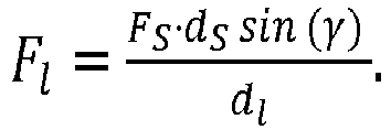

- As the torque Ml is given as Ml = Fl·r sin (δ), -MC reads:


- Expressing dl as function of ϕ and FS as a function of Δl yields:

- The description of
Fig. 2 can be read equally with respect toFig. 3 . -
- 3
- clutch operating means (e.g. a push rod)
- 4
- spring
- 10
- disc
- 11
- rotary axis
- 12
- pin
- 13
- traveling path of the pin (trajectory)
- 19
- disc extension
- 20
- lever
- 21
- pivot axis
- 22
- contacting surface of
lever 20 - 30
- motor
- 40
- reduction gear
- 80
- support
- 90
- clutch
- 91
- input shaft
- 92
- output shaft
- δ
- angle between the tangents of contacting
surface 22 and traveling path of thepin 12 at their contacting point - ϕ
- angle between the rays being defined by the rotary axis and the pin's center and the rotary axis and the pivot axis
-
r - vector from the
rotary axis 11 to the pin's center - d min
- minimum distance between the pins's center and the
pivot axis 21 -
d S - lever arm where force of the spring acts on the lever
-
d 0 - vector from the rotary axis of the
pin 12 to the connection of the clutch operating means -
F S - force provided by the
spring 4 to thelever 20 at the lever armd S -
F C - force provided by the clutch spring via the clutch operating means 3 to the
disc 12/19 at the lever armd 0 - t 1
- first tangent (tangent of contacting surface 22)
- t 2
- second tangent (tangent pin's traveling path 13)
Claims (10)
- A clutch actuation mechanism for actuating a clutch operating means (3) of a spring loaded friction clutch, the clutch actuation mechanism comprising at least a rotary disc (10) for being connected to the clutch operating means (3), said disc (10) being supported by a radial bearing defining the disc's rotary axis (11) and being coupled to a motor to provide a first torque to said disc (10),
characterized in that- a pin (12) is attached to the disc (10) with an offset (r) from the disc's rotary axis (11),- a lever (20) has a contacting surface (22) and is pivoting supported to pivot around a lever's pivot axis (21), wherein the pivot axis (21) and the rotary axis (11) are parallel (±5°),- a spring (4) forces the lever (20) with its contacting surface (22) against the pin (12) to thereby provide an additional torque to the disc (10), wherein the pin (12) travels over the contacting surface (22) when the disc (10) rotates to open or close the spring loaded clutch via the clutch operating means. - The clutch actuation mechanism of claim 1
characterized in that
the contacting surface is curved. - The clutch actuation mechanism of claim 1 or 2
characterized in that- the pin (12) contacts the contacting surface (20) at a first position, said first position defining a first tangent (t 1) of the contacting surface,- the path (13) of the pin (12) when rotating the disc (10) defines a second tangent (t 2) at said first position,- said first and second tangents (t 1, t 2) intersect at an angle δ,- the contacting surface (22) is curved to provide an angle δ with
r ) pointing from the rotary axis 11 to the pin's (12) center and the ray starting at the rotary axis (11) through the pivot axis (21) and, dmin is the minimum distance between the pin's center (12) and the pivot axis (22), F 0 is the force provided by the spring with at a length l0 to the lever at a distance ds from the pivot axis (21), k the spring's constant and Δl the deflection of the spring (3) relative to l 0, where it is assumed thatF 0 andk are orthogonal (±10°) todS and Δδ ≤ 10°. - The clutch actuation mechanism of one of the preceding claims characterized in that

F 0 andk withdS , and in that the restriction of orthogonality betweenF 0 ,k anddS is omitted. - The clutch actuation mechanism of one of the preceding claims characterized in that
the pin (12) is rotatable supported by the disc (10). - The clutch actuation mechanism of one of the preceding claims characterized in that
it comprises a support structure supporting the radial bearing of the disc (10) and the pivotable support mechanism of the lever (20) and the motor (30). - The clutch actuation mechanism of one of the preceding claims characterized in that
the motor (30) is an electro motor being coupled to the disc (10) via a reduction gear. - The clutch actuation mechanism of one of the preceding claims characterized in that
the contacting surface has at least a first segment where the angle δ is zero (±5°). - The clutch actuation mechanism of claim 8
characterized in that
the first segment contacts the pin (12) when MC < Mmin , wherein Mmin is smaller than 10% of the maximum torque required the compensate the clutch spring when opening or closing the clutch. - The clutch operating mechanism of one of the preceding claims characterized in that
the disc is a disc segment or a shaft.
Priority Applications (5)
| Application Number | Priority Date | Filing Date | Title |
|---|---|---|---|
| EP16164473.7A EP3228894A1 (en) | 2016-04-08 | 2016-04-08 | Clutch actuation mechanism |
| PCT/EP2017/057955 WO2017174562A1 (en) | 2016-04-08 | 2017-04-04 | Clutch actuation mechanism |
| DE112017001897.8T DE112017001897T5 (en) | 2016-04-08 | 2017-04-04 | Clutch actuating mechanism |
| CN201780021919.0A CN108884879B (en) | 2016-04-08 | 2017-04-04 | clutch actuating mechanism |
| US16/155,253 US10794431B2 (en) | 2016-04-08 | 2018-10-09 | Clutch actuation mechanism |
Applications Claiming Priority (1)
| Application Number | Priority Date | Filing Date | Title |
|---|---|---|---|
| EP16164473.7A EP3228894A1 (en) | 2016-04-08 | 2016-04-08 | Clutch actuation mechanism |
Publications (1)
| Publication Number | Publication Date |
|---|---|
| EP3228894A1 true EP3228894A1 (en) | 2017-10-11 |
Family
ID=55701849
Family Applications (1)
| Application Number | Title | Priority Date | Filing Date |
|---|---|---|---|
| EP16164473.7A Withdrawn EP3228894A1 (en) | 2016-04-08 | 2016-04-08 | Clutch actuation mechanism |
Country Status (5)
| Country | Link |
|---|---|
| US (1) | US10794431B2 (en) |
| EP (1) | EP3228894A1 (en) |
| CN (1) | CN108884879B (en) |
| DE (1) | DE112017001897T5 (en) |
| WO (1) | WO2017174562A1 (en) |
Cited By (1)
| Publication number | Priority date | Publication date | Assignee | Title |
|---|---|---|---|---|
| CN114738627A (en) * | 2022-04-26 | 2022-07-12 | 王志院 | Intelligent traffic monitoring system and monitoring method |
Citations (3)
| Publication number | Priority date | Publication date | Assignee | Title |
|---|---|---|---|---|
| GB2117076A (en) * | 1982-03-18 | 1983-10-05 | Valeo | Control mechanism for a mechanical coupling device |
| DE3502341A1 (en) * | 1984-01-25 | 1985-07-25 | Valeo, Paris | CONTROL FOR A CLUTCH |
| DE19710365C2 (en) | 1996-05-02 | 2003-04-03 | Zf Sachs Ag | actuator |
Family Cites Families (5)
| Publication number | Priority date | Publication date | Assignee | Title |
|---|---|---|---|---|
| DE3501341A1 (en) | 1984-12-22 | 1986-07-03 | Klöckner-Humboldt-Deutz AG, 5000 Köln | Solid-bowl conveyor screw centrifuge |
| FR2663887B1 (en) * | 1990-06-29 | 1995-06-30 | Valeo | ACTUATOR, ESPECIALLY FOR THE CONTROL OF A MOTOR VEHICLE CLUTCH. |
| DE102008013054B4 (en) * | 2008-03-06 | 2010-04-22 | Getrag Getriebe- Und Zahnradfabrik Hermann Hagenmeyer Gmbh & Cie Kg | Actuation mechanism for engaging and disengaging a separating clutch with a turnable segment |
| DE102013008071A1 (en) * | 2013-05-10 | 2014-11-13 | Borgwarner Inc. | Coupling device with lockable actuator |
| GB201420522D0 (en) * | 2014-11-19 | 2014-12-31 | Ap Automotive Products Srl | Electro-Mechanical actuators |
-
2016
- 2016-04-08 EP EP16164473.7A patent/EP3228894A1/en not_active Withdrawn
-
2017
- 2017-04-04 CN CN201780021919.0A patent/CN108884879B/en active Active
- 2017-04-04 WO PCT/EP2017/057955 patent/WO2017174562A1/en not_active Ceased
- 2017-04-04 DE DE112017001897.8T patent/DE112017001897T5/en active Pending
-
2018
- 2018-10-09 US US16/155,253 patent/US10794431B2/en active Active
Patent Citations (3)
| Publication number | Priority date | Publication date | Assignee | Title |
|---|---|---|---|---|
| GB2117076A (en) * | 1982-03-18 | 1983-10-05 | Valeo | Control mechanism for a mechanical coupling device |
| DE3502341A1 (en) * | 1984-01-25 | 1985-07-25 | Valeo, Paris | CONTROL FOR A CLUTCH |
| DE19710365C2 (en) | 1996-05-02 | 2003-04-03 | Zf Sachs Ag | actuator |
Cited By (2)
| Publication number | Priority date | Publication date | Assignee | Title |
|---|---|---|---|---|
| CN114738627A (en) * | 2022-04-26 | 2022-07-12 | 王志院 | Intelligent traffic monitoring system and monitoring method |
| CN114738627B (en) * | 2022-04-26 | 2024-01-02 | 四川智慧高速科技有限公司 | An intelligent traffic monitoring system and monitoring method |
Also Published As
| Publication number | Publication date |
|---|---|
| CN108884879A (en) | 2018-11-23 |
| WO2017174562A1 (en) | 2017-10-12 |
| CN108884879B (en) | 2020-09-08 |
| US20190040918A1 (en) | 2019-02-07 |
| US10794431B2 (en) | 2020-10-06 |
| DE112017001897T5 (en) | 2018-12-27 |
Similar Documents
| Publication | Publication Date | Title |
|---|---|---|
| CN102834634B (en) | Coupling assembly | |
| JP4430044B2 (en) | Drive device | |
| CN101581341B (en) | Adjustment mechanism for inserting and extracting a separation coupling with rotating curve segment | |
| US7896146B2 (en) | Clutch device utilizing brushless motor | |
| TWI568634B (en) | Back pedaling tranmission for electrobicycles and process for the controlled coupling of output and motor of an electrobicycle | |
| US8556057B2 (en) | Transfer case with clutch actuator | |
| CN112534162A (en) | Actuator device and electric drive device having such an actuator device | |
| EP3105463B1 (en) | An actuator for a dog clutch and a method for its control | |
| US20090032352A1 (en) | Motor actuated range shift and on demand 4wd | |
| EP1714850A1 (en) | Planetary roller driving device and steering apparatus comprising the same | |
| RU2012108374A (en) | DRIVER TO ENSURE CLOSING THE LOCK OF THE OPENING PART OF THE VEHICLE AND THE RELATED DEVICE | |
| EP2280182A1 (en) | A clutch member with motion transmission mechanism with coil spring and friction engagement | |
| US10794431B2 (en) | Clutch actuation mechanism | |
| US5934433A (en) | Friction clutch having an actuator for automated operation | |
| RU2691907C1 (en) | Electromechanical actuator for actuation of system transmitting force by means of friction force closure | |
| US20030121749A1 (en) | Clutch engaging and disengaging apparatus | |
| US10731731B2 (en) | Transmission device for a motor vehicle | |
| KR101060036B1 (en) | Transfer case | |
| CN104006028A (en) | Hydrostataktor | |
| EP2098762B1 (en) | Electromechanical actuator for automatic gearbox comprising an effort controller | |
| JP2007078134A (en) | Driving force distribution device | |
| EP3553346A1 (en) | Gearshift actuator | |
| CN102076984B (en) | Clutch device, particularly for motor vehicle, of type comprising power-assisted operating device | |
| CN113508245A (en) | Method for operating a clutch with an actuator | |
| CN113167378A (en) | Transmission unit for a motor vehicle with a back drive and motor vehicle comprising said transmission unit |
Legal Events
| Date | Code | Title | Description |
|---|---|---|---|
| PUAI | Public reference made under article 153(3) epc to a published international application that has entered the european phase |
Free format text: ORIGINAL CODE: 0009012 |
|
| STAA | Information on the status of an ep patent application or granted ep patent |
Free format text: STATUS: THE APPLICATION HAS BEEN PUBLISHED |
|
| AK | Designated contracting states |
Kind code of ref document: A1 Designated state(s): AL AT BE BG CH CY CZ DE DK EE ES FI FR GB GR HR HU IE IS IT LI LT LU LV MC MK MT NL NO PL PT RO RS SE SI SK SM TR |
|
| AX | Request for extension of the european patent |
Extension state: BA ME |
|
| RAP1 | Party data changed (applicant data changed or rights of an application transferred) |
Owner name: HELLA GMBH & CO. KGAA |
|
| STAA | Information on the status of an ep patent application or granted ep patent |
Free format text: STATUS: THE APPLICATION IS DEEMED TO BE WITHDRAWN |
|
| 18D | Application deemed to be withdrawn |
Effective date: 20180412 |